
Abstract
For automobile applications, sandwich-structured materials are used for thin components that are subjected to relatively small loadings. Other components are usually assembled onto the sandwich panels. In order to ensure adequate connection strength, joining inserts are added to the structures. The joining insert and honeycomb core are connected by adhesives and are used to connect the sandwich structure with the other components. In this work, tensile tests were performed on four different types of inserts for sandwich panels. The ultimate loads of inserts with different shapes and sizes are measured to determine the effect of the insert design on panel strength. The experimental results show that the regular hexagonal shaped has the most influence on the ultimate load.
Introduction
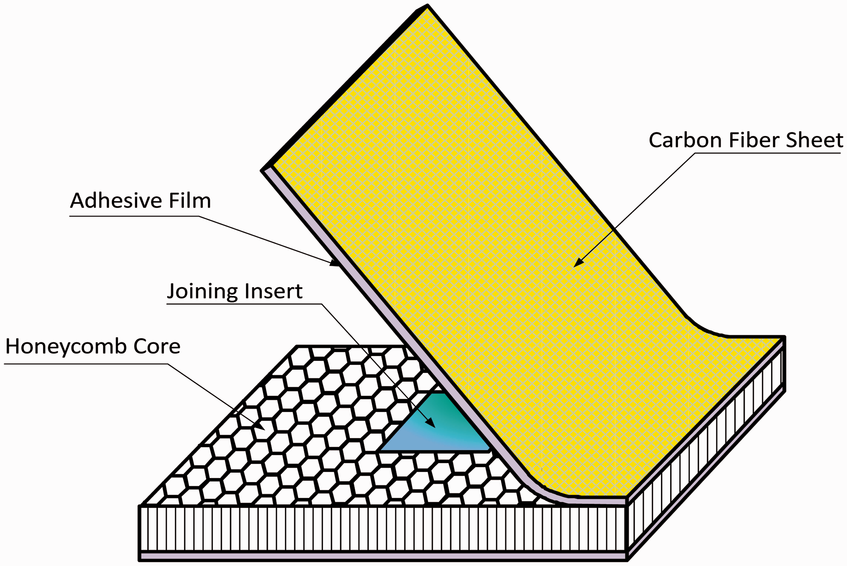
Composite materials are widely used in aerospace, automobile, and other applications due to its high specific strength, modulus, and excellent design ability.1–3 The anisotropy of the composite material makes the design of its connecting structure complex. A sandwich-structured material is a kind of special composite structure, which is made up of a top panel, bottom panel, core, and adhesive joint.4,5 The load transfer method in the sandwich structure is similar to the flanged beam. The core is primarily used to bear the transverse shear load and separate the two panels to improve integral rigidity. In order to make every part of the structure bear load, the adhesive film between the panel and core need to transfer the load with at least the same strength as the core material. Core material is generally divided into honeycomb core and foam core.6,7 An insert structure is commonly used to connect parts in aerospace structures and is the main load-bearing component in the joint between the sandwich panel and other instruments. They can be divided into metal panel insert structures, composite panel insert structures, and sandwich panel inserts structures. 8 Considering the weight reduction requirements in automotive design, the honeycomb core is commonly used in insert structure design. The honeycomb core has high vertical load-bearing strength, but does not withstand transverse loads. This problem is solved by using an aluminum alloy insert, which is pre-drilled for connection and replaces part of the honeycomb core to improve local strength.
There are a few published works on inserts and most focus on the calculation method. The available literature shows a lack of calculation methods and most inserts are designed by simple formulas. Several researchers have investigated sandwich structures with inserts. Elena et al. 9 considered the local bending effects induced in the vicinity of the inserts in sandwich panels. Thomsen and Rits solved numerically the stress in sandwich plates with through-the-thickness inserts subjected to axisymmetric and nonaxisymmetric external loadings with the multisegment method of integration. 10 Bozhevolnaya and Lyckegaard 11 suggested a design of the core insert, which substantially diminished the level of impairing local effects in the face material. Although many researchers have investigated applications of sandwich structures to various parts of machine tools, airplanes, ships, satellites, and so on, studies of various insert shapes in a sandwich panel are rare.
In this paper, a sandwich structure with an insert was chosen as the research subject. The effects of four different types of joining inserts on the pull-out strength were investigated.
Experimental characterization
In this paper, sandwich plates with joining inserts are used in a vehicle body structure (Figure 1). In this experiment 6061 aluminum alloy, aluminum honeycomb with 20 mm thickness, and T300 carbon-fiber fabric are used to fabricate the joining insert. The structure of the honeycomb laminated plates is shown in Figure 2. The purpose of the experiment is to optimize the shape and size of the joining insert to maximize the tensile strength of the whole structure through the measurement and analyses of the samples’ limit loads and failure mechanisms.
A vehicle body made with sandwich-structured laminate panels. Sketch of the sandwich-structured laminate panel with honeycomb core.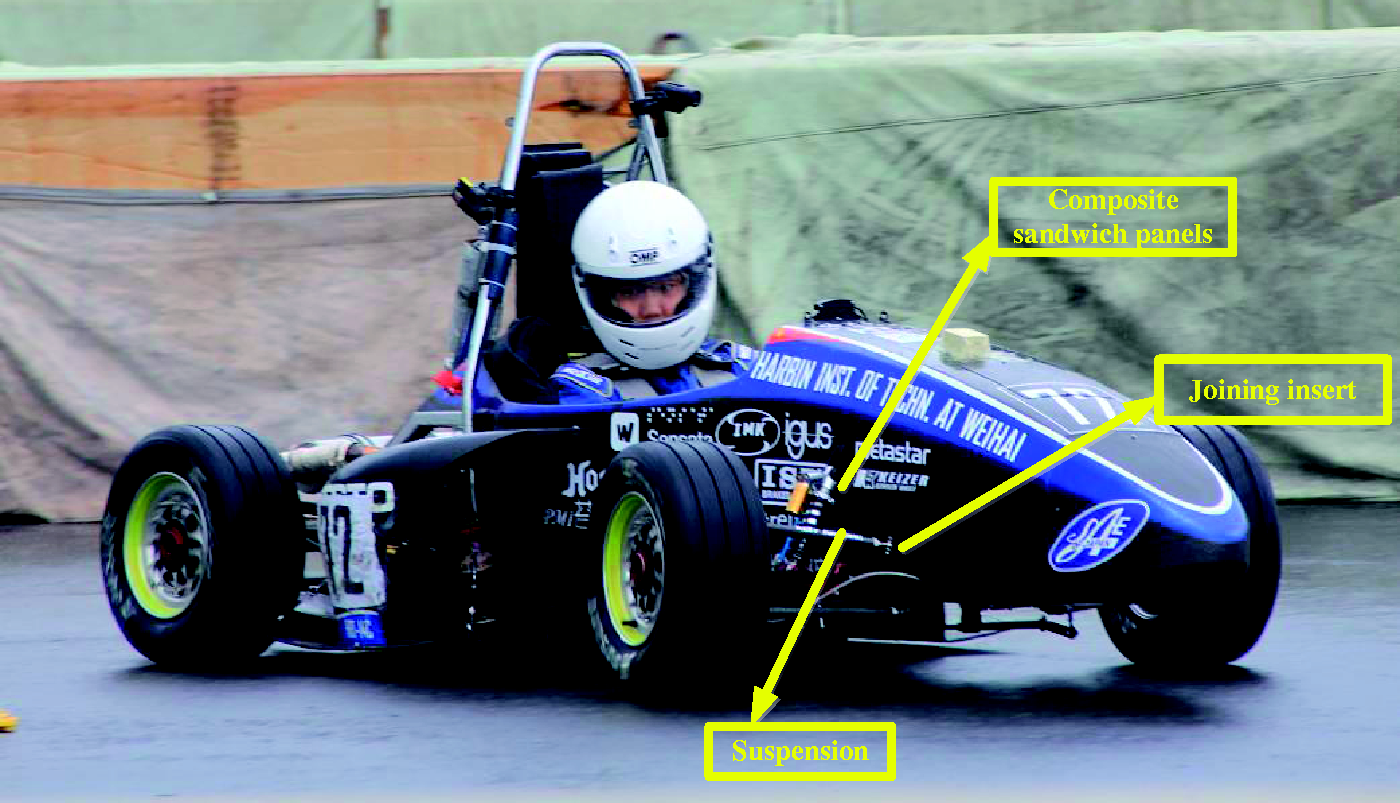
Specimen preparation
Specimens of aluminum honeycomb laminated plates with joining inserts were prepared for the study.12,13 Four common polygon shapes (equilateral triangle, square, regular hexagon, and circle) were used for the aluminum alloy joining inserts. The surfaces were clean and smooth, with a roughness of Ra = 6.3 Four shapes of the joining inserts.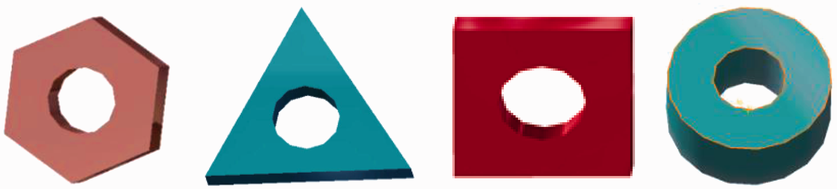
The honeycomb laminated plates were manufactured in the same environment. All parts were made to the same size and with the same manufacturing method, except for the shape of the joining inserts (Figure 4).
Lateral view of specimen components.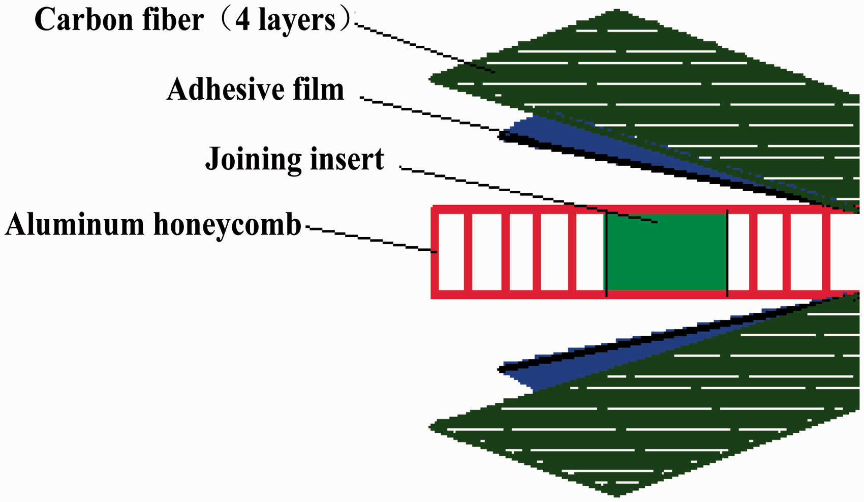
An appropriate specimen size was chosen according to the size of the experimental platform. The carbon fiber sheets, film adhesive, and honeycomb core were fabricated to a size of 100 × 200 mm2. A hole was drilled into the aluminum honeycomb core and the joining insert was attached. The polygon insert and the honeycomb remained symmetrical. T300 unidirectional prepreg carbon fiber sheets were stacked along the 0° direction with four layers at each face. After the fabrication was finished, the specimens were degassed in a vacuum bag and thermoset. During this process, toughened glass was used as the experimental platform and the mold discharging agent was smeared on it uniformly. The cure cycle is shown in Figure 5. After the thermosetting, specimens were labeled with the origin data and put in order for the experiment.14,15
Specimen cure cycle.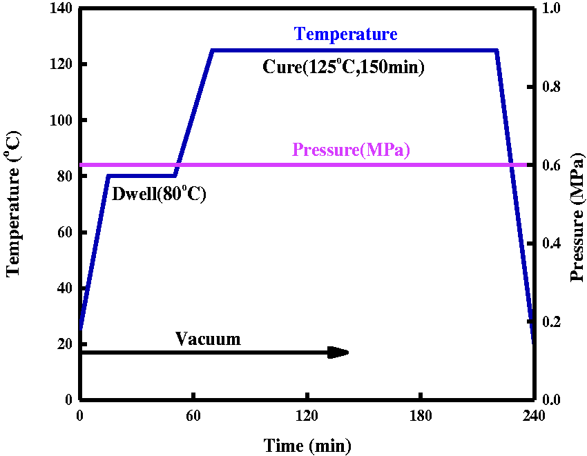
Experimental set-up
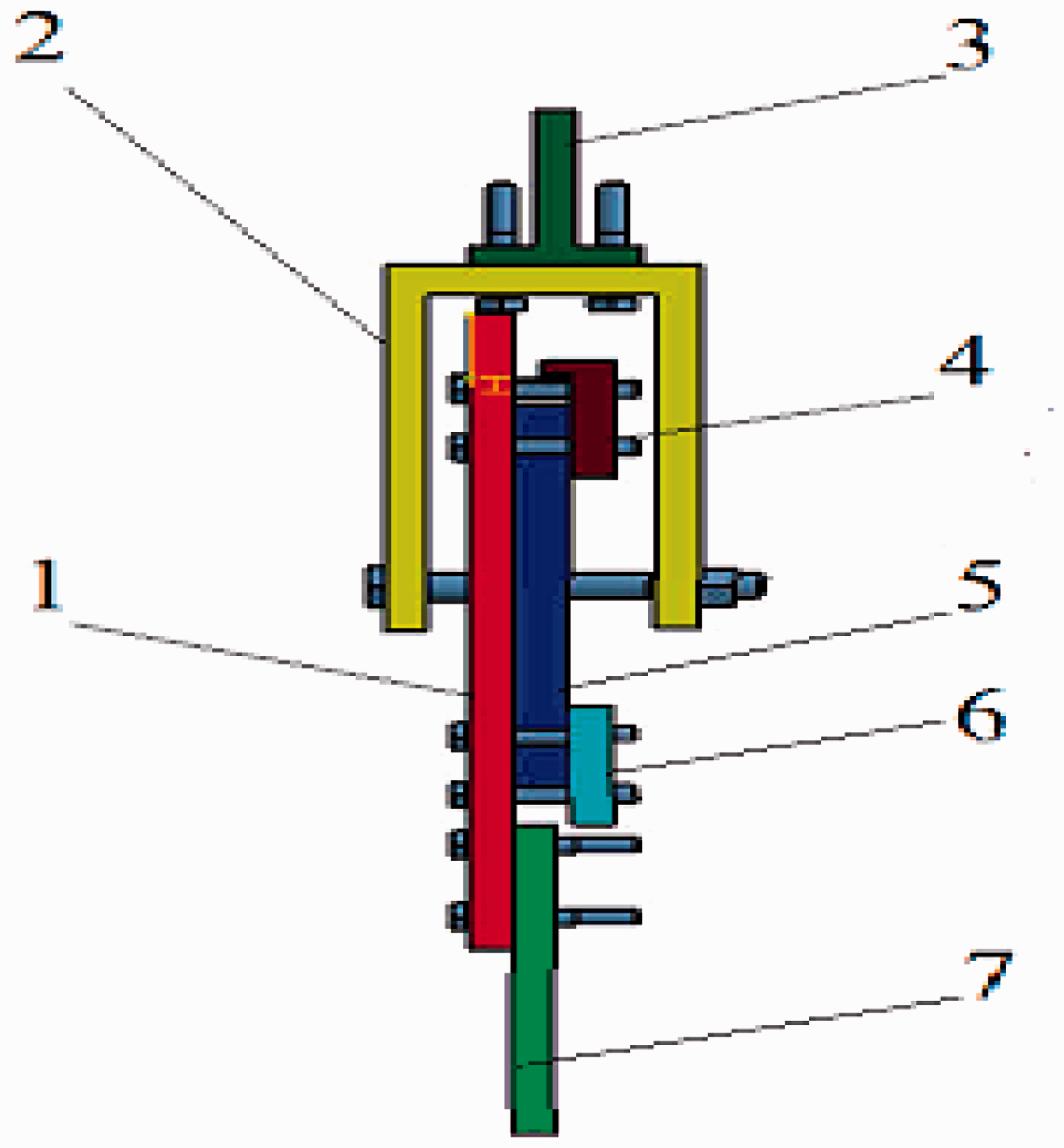
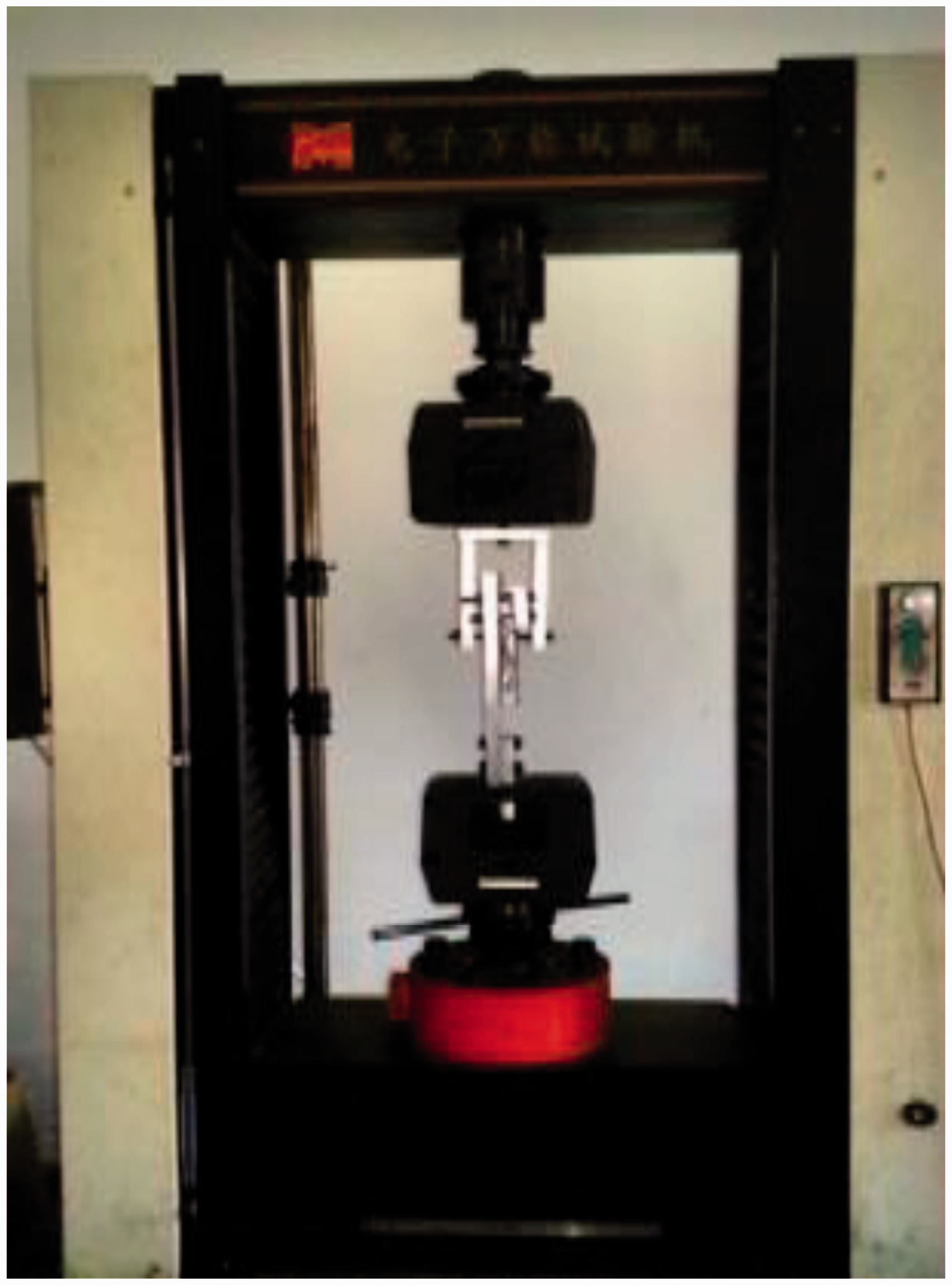
A computer-controlled universal test instrument (CSS-44300) was used in this experiment.16–18 The performance indexes of this machine were a maximum load of 300 kN and a range of velocity for beam displacement of 0.005–500 mm/min. For the experiment, the stretching angles were set at 90° and 0°. A modular method that could be easily assembled was used for the set-up design. Six components were designed and connected to set up the quasi-static tension tests.
The 90° quasi-static tension test is illustrated in Figure 6 (the specimen is in blue). The test was designed to pull the joining insert out of the structure by applying force to the bolt. No. 1 and No. 2 in Figure 6 were used to clamp the platform and No. 3 and No. 6 were the clamps used to prevent the specimen from moving up and down. The fixture was disassembled and reassembled for the 0° quasi-static tension test (Figure 7). No. 3 and No. 7 were used to connect the specimen to the platform. No. 2, which was connected to the bolt, was used for the tension test of specimen. No. 4 was used to prevent the specimen from moving up and down.
Fixture set-up for 90° test. Fixture set-up for 0° test.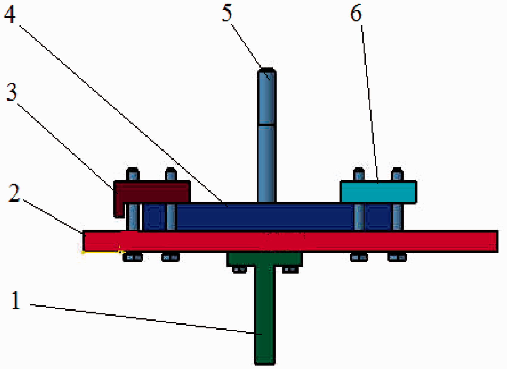
Experimental methods
The 90° quasi-static tension test was performed first.19–21 The specimen was set up as shown in Figure 8 and a vertical tension test was performed with a loading rate of 1 mm/min. After loading, the load–displacement curve was obtained and the experimental data was recorded. The 0° quasi-static tension test was conducted (Figure 9) in the same manner as that for the 90° test.
Quasi-static tensile test set-up for 90° test. Quasi-static tensile test set-up for 0° test.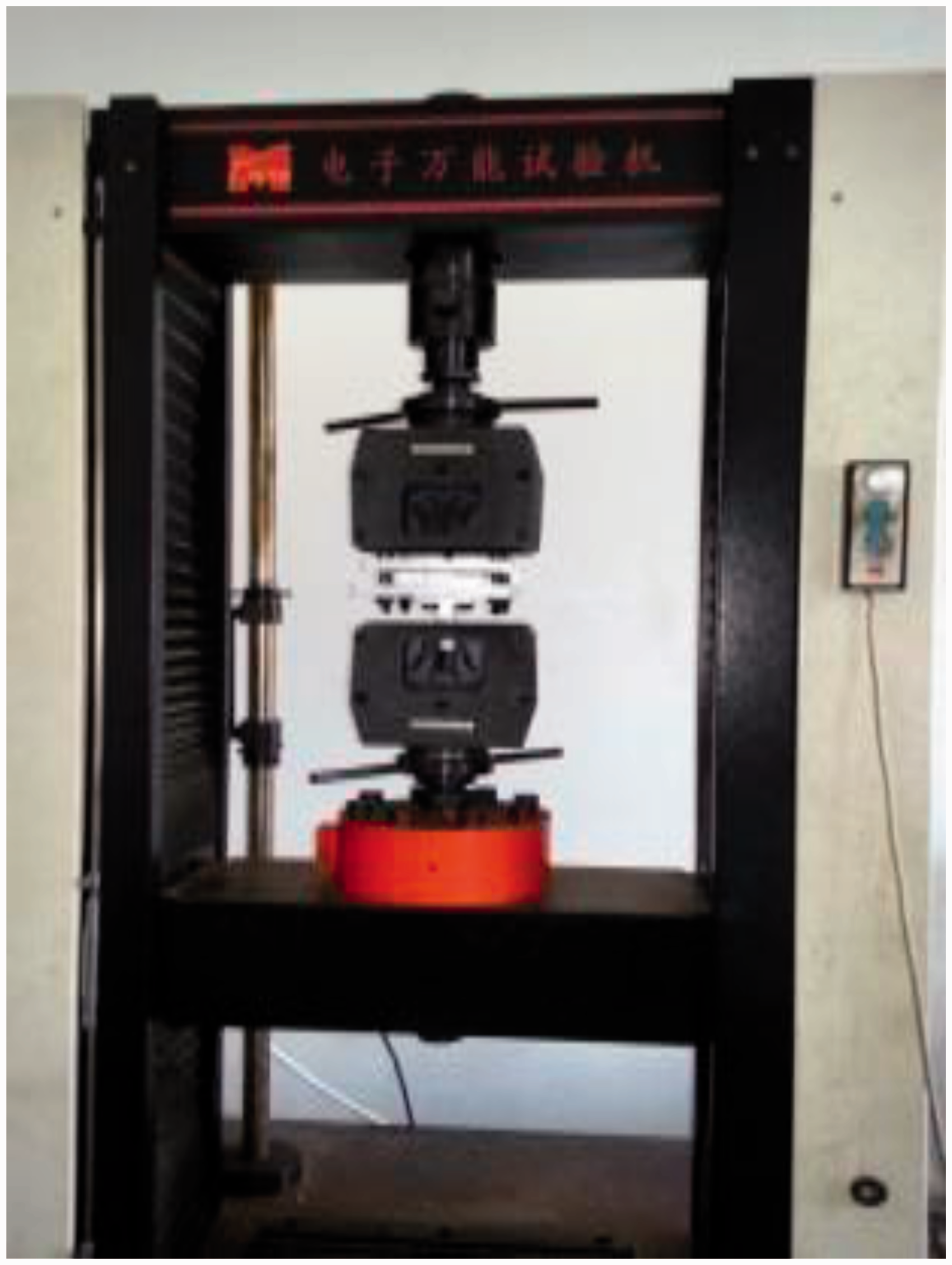
Results and discussion
Quasi-static tensile testing results
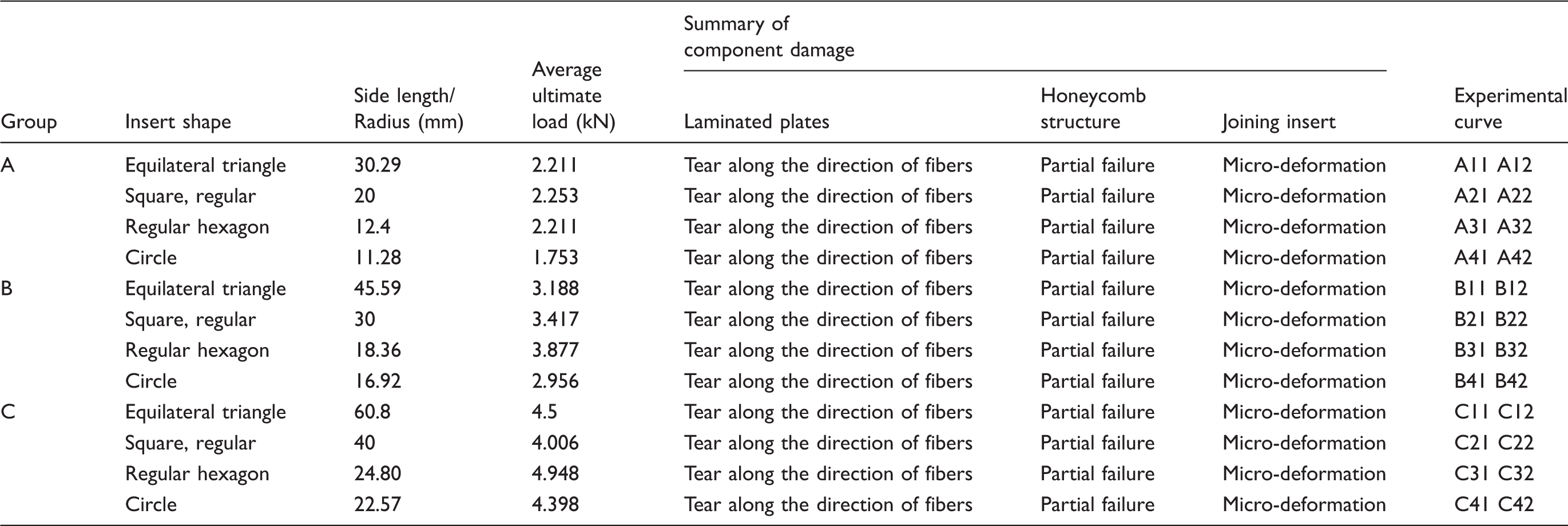
Results of tensile testing on joining inserts (90°).
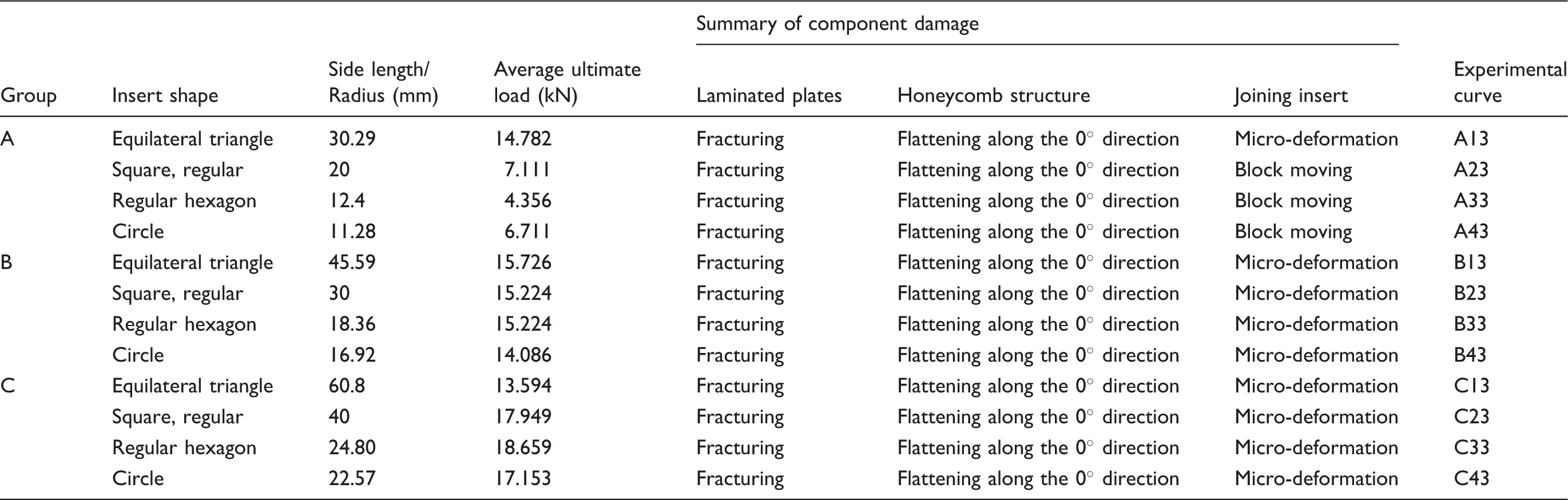
Results of tensile testing on joining inserts (0°).
Analysis of experimental results
Quasi-static tensile test at 90°
The carbon-fiber sheet was torn along the direction of the fiber by the joining insert; the honeycomb core was squeezed and fractured. First, the bottom layer of the carbon-fiber sheet was fractured, which in turn compressed the honeycomb core. Then, the upper layer of carbon-fiber degummed and debonded along the direction of the fibers, leading to a gradual shear break. The tension decreased rapidly after the fibers fractured and then rose sharply again. The damage conditions of specimen A21 during the 90° test represent the typical level of damage for all specimens tested at this test condition (Figure 10).
Typical degradation of specimen during 90° test.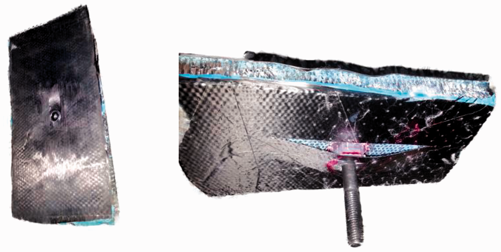
A load–displacement curve for specimen A21 is shown in Figure 11. The load slightly decreased because of the clamping gap of the test set-up. The load rose continuously with the effect of the laminated plates and reached a peak. Finally, the load decreased gradually to zero with the complete break of the test specimen.
Load–displacement curve of specimen A21 in 90° test.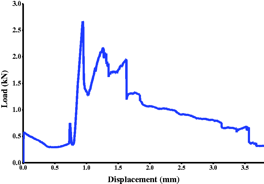
Quasi-static tensile test at 0°
The fibers of most of the specimens fractured and debonded in the 0° test, with the degumming and compression of the honeycomb core (Figure 12). This led to the fibers and aluminum honeycomb stacking up at the edge, making the load rise sharply. The ultimate load was recorded.
Typical deformation of specimen during the 0° test.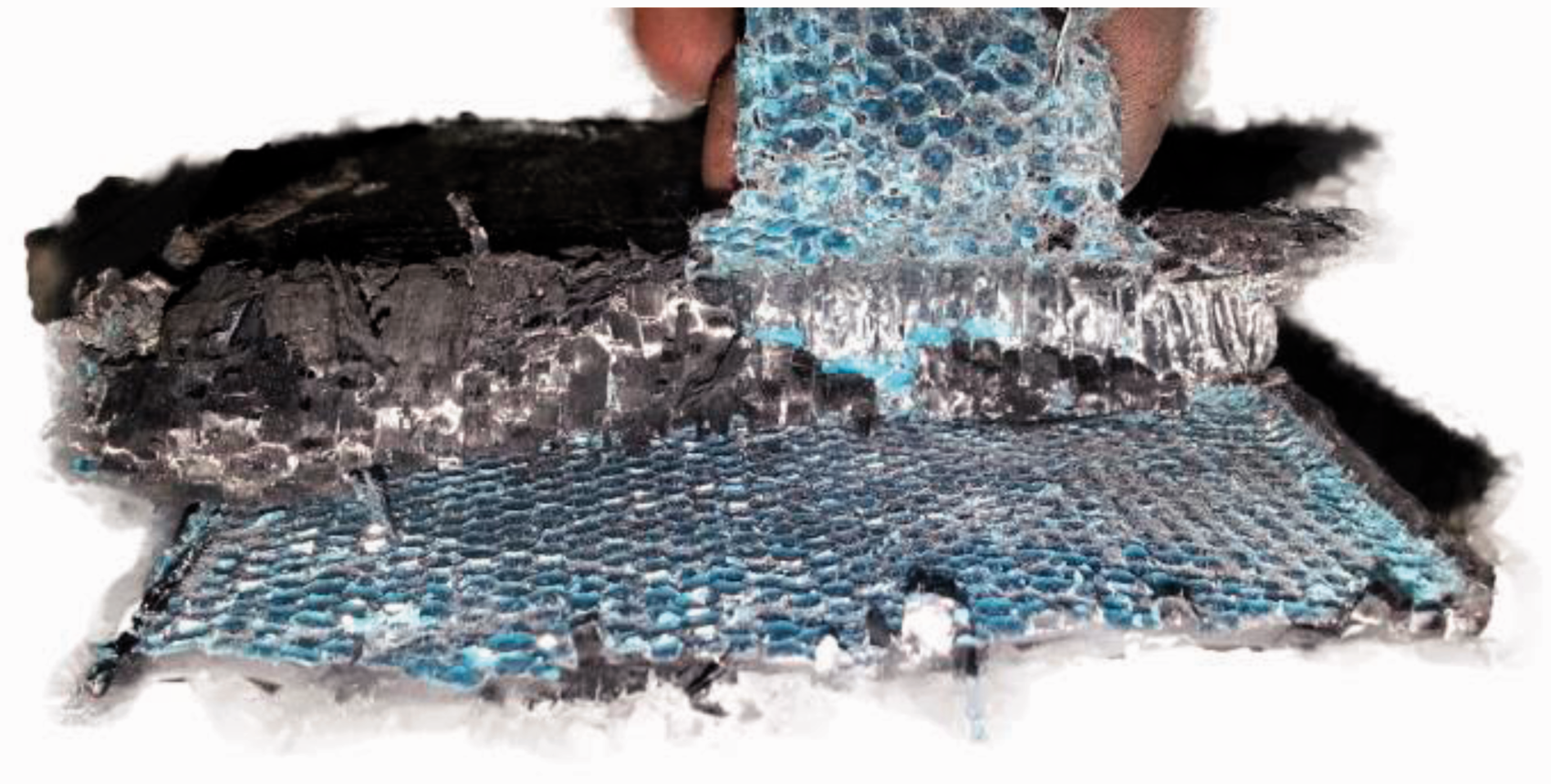
When the sectional area of the joining insert was too small, the insert suddenly slipped. This led to the ultimate load decreasing unexpectedly after reaching peak load. This behavior was observed with Specimens A23, A33, and A43.
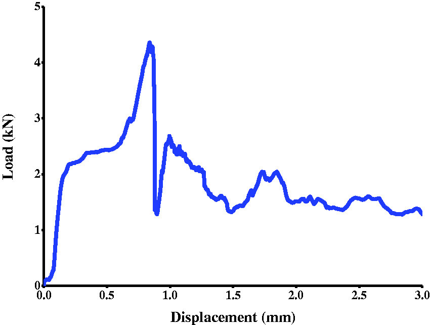
As is shown in Figure 13, the joining insert slipped within the structure before failure of the laminated plates because of the small size of the insert. The small insert caused direct contact between the bolt, the carbon-fiber sheet, and the honeycomb core. The honeycomb structure and laminated plates were easily destroyed, including honeycomb compression and distortion failure, due to this contact. The load rose steadily before the insert slipped (Figure 14) and then the load decreased sharply owing to the insert slipping. The load rose slightly owing to the compression of laminated plates and honeycomb core and then rose and fell over time because of the stacking damage of the whole structure. Finally, the load fell to zero with the successive damage of the structure.
The phenomenon of the joining insert slipping inside the structure. Load–displacement curve of specimen A21 for the 0° test.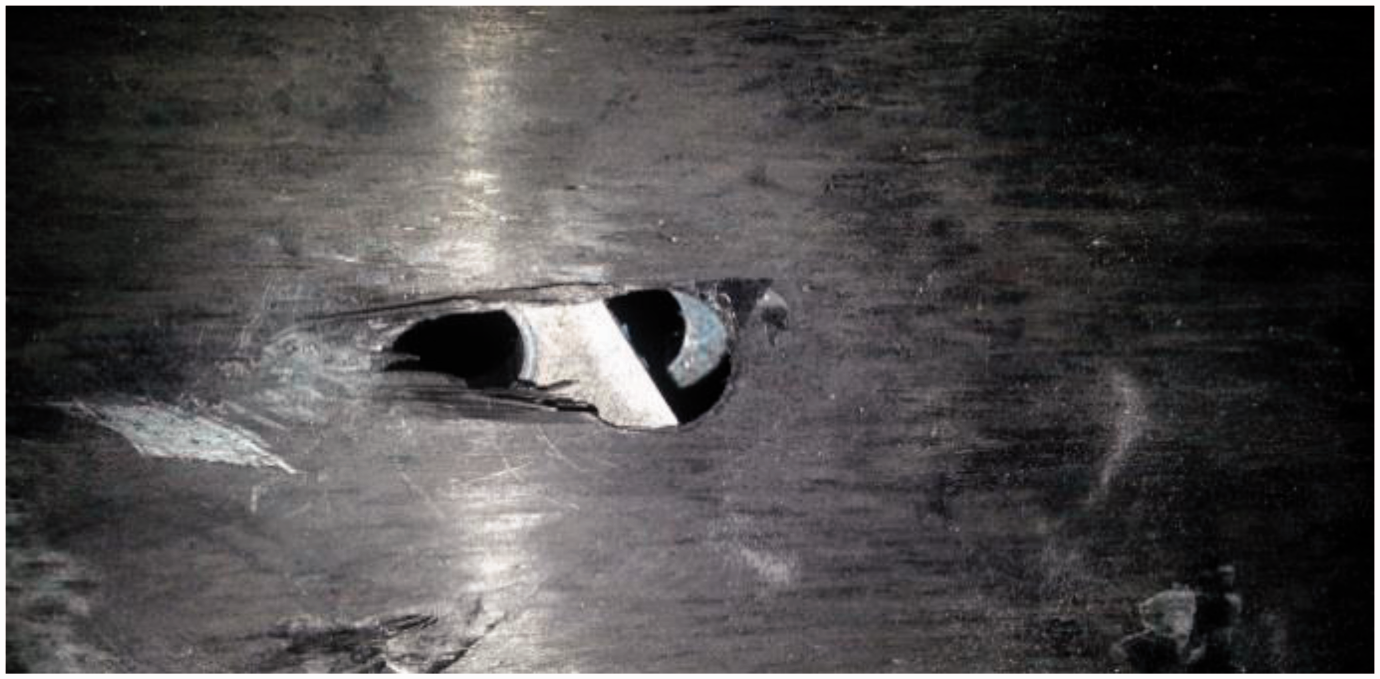
Experimental conclusion
Quasi-static tensile test at 90°
With the increase in side length, the ultimate load increases for the condition where the sectional areas were equal. The regular hexagonal-shaped insert yielded the highest ultimate load in each group, but when the numbers of edges approaches infinity (circular), the ultimate load decreases. Group C was unique in that the ultimate load decreased slightly for the square-shaped insert. This did not impact the conclusion. With an increase in sectional area, the ultimate load increased among all groups (Figure 15).
Ultimate load as a function of insert shape for the 90° test.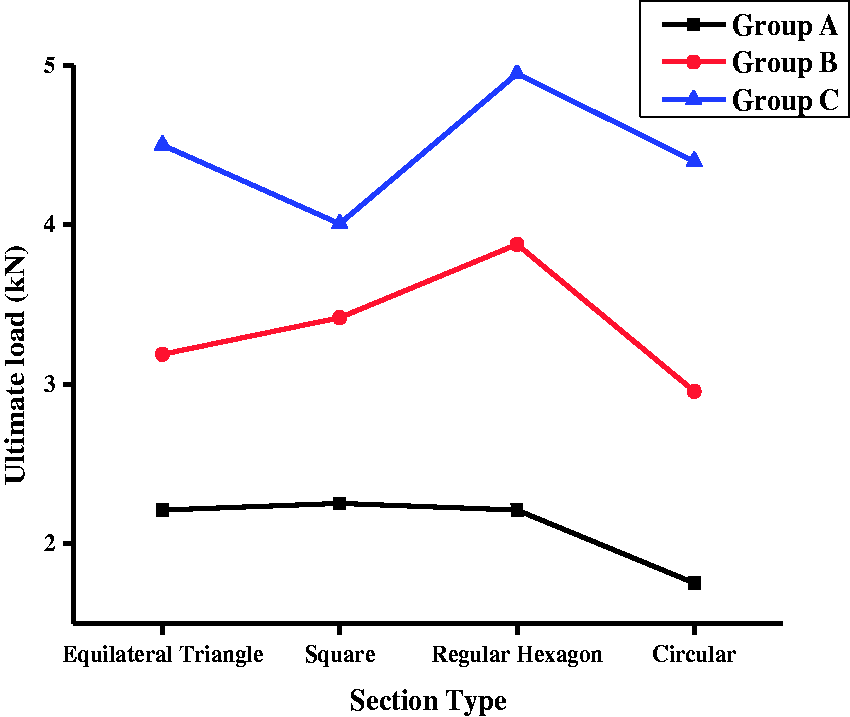
As shown in Figure 16, the ultimate load increases with the increase in sectional area when the insert shape is fixed. It is suggested that the appropriate sectional area can be determined according to the ultimate load trend in practical applications. Therefore, the optimal sectional area can be determined according to the ultimate load trend, along with the strength requirements, and material properties. No conclusions can be drawn regarding the effect of insert shape on the ultimate load.
Ultimate load as a function of the sectional area size for the 90° test.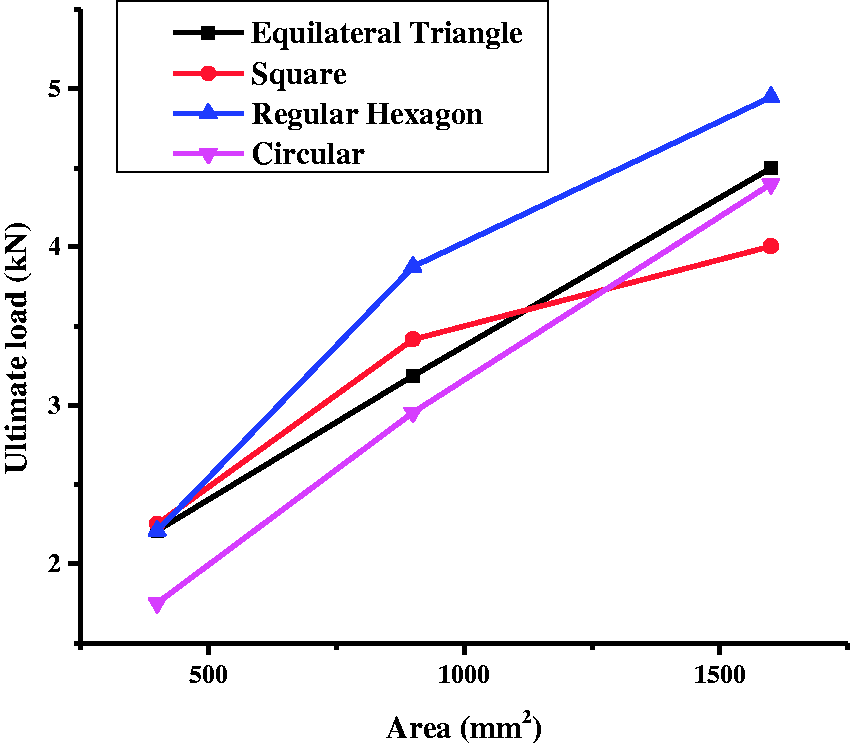
Quasi-static tensile test of 0°
As shown in Figure 17, the ultimate load changed approximately 5% with the insert shape when the sectional area is fixed with the exception of Group A. Groups B and C have the heaviest ultimate load with the regular hexagonal-shaped insert, followed by the square-shaped insert. However, the joining insert slipped when its sectional area was very small, which led to the sharp decrease in load. This is seen for the square-shaped, regular hexagonal-shaped and circular-shaped inserts in Group A. The ultimate load for each insert shape increased with the increase in sectional area, with the exception of the triangular-shaped insert.
Ultimate load as a function of insert shape for the 0° test.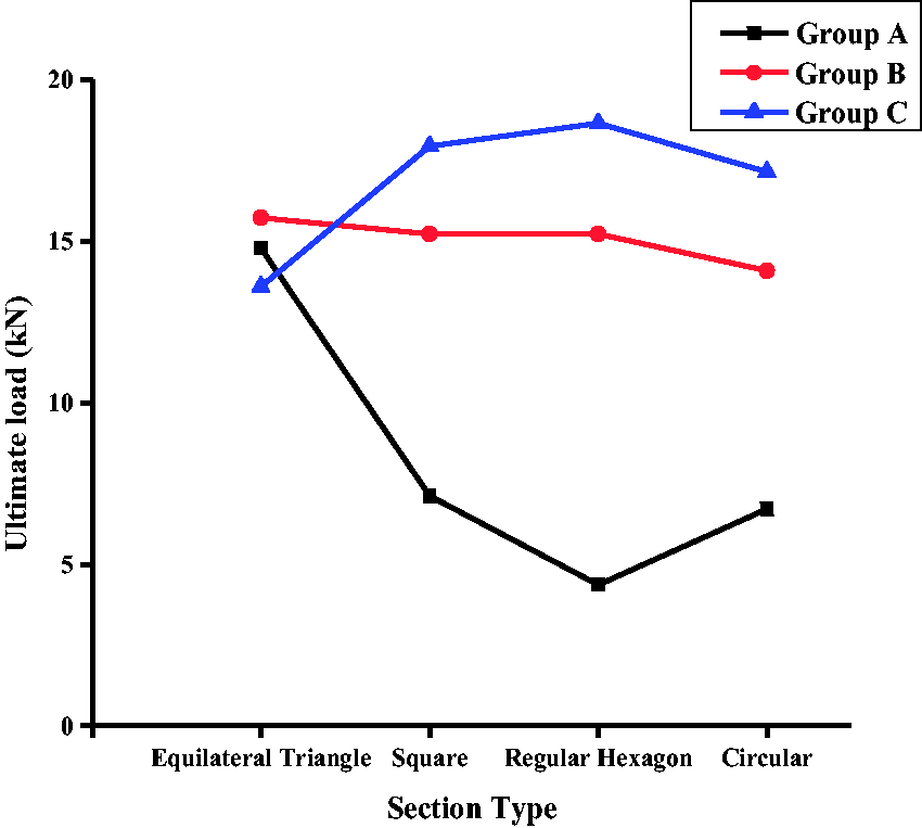
As shown in Figure 18, the ultimate load increased with an increase in the sectional areas when the insert shape is fixed. This is the same result as that for the testing at 90°. The ultimate load peaked with the regular hexagonal-shaped insert. Similar to testing done 90°, no conclusion can be made regarding the effect of insert shape on load.
Ultimate load as a function of sectional area for the 0° test.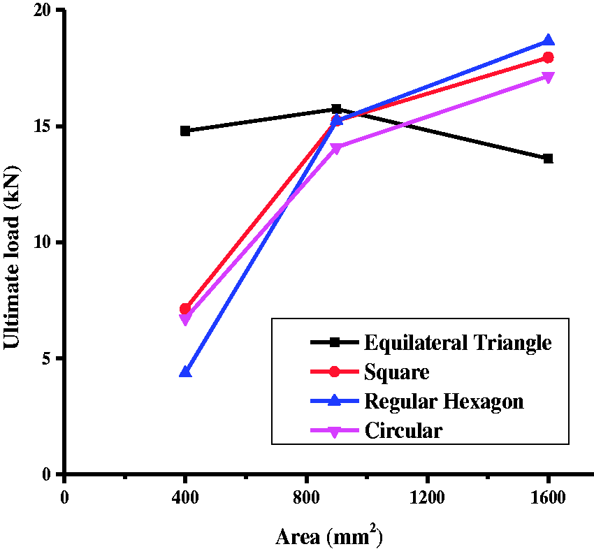
In summary, the regular hexagonal shaped has the most influence on the ultimate load. The ultimate load for the circular-shaped insert, where the number of edges is infinite, is lighter than that of the regular hexagon. When the section area is too small, particularly less than 100 mm2, it is easy for the joining insert to slip out. This is because the bonding of the adhesive film is not adequate. In real-world applications, an insert less than 100 mm2 should be avoided. The ultimate load in the 0° test is heavier than that in the 90° test, because the strength along the main axis is higher than that in tangential fiber direction.
Conclusion
From this study, it can be concluded that tensile strength increases with an increase in the numbers of edges among the four shapes of joining inserts. The regular hexagonal-shaped insert has the best tensile strength. However, when the numbers of edges approaches infinity, as is the case with the circular-shaped insert, the tensile strength decreases slightly. Tensile strength increases with an increase in the sectional area, when the insert shape is fixed. With consideration for this behavior, the lightest and strongest joining insert can be obtained. However, when the sectional area is too small (< 100 mm2), the joining insert can easily slip out of the sandwich structure because the bond strength of the adhesive film is not adequate. In practical applications, inserts less than 100 mm2 should be avoided. The conclusion of this paper is new and can be useful in many fields, for example, the HRT team in our university. Their car’s body is made of carbon fiber/aluminum honeycomb sandwich structures, the body need to be connected with many parts, so the conclusion can be used to strengthen the connection and optimize the whole body. The sandwich structure is also widely used in automobile, aircraft and aerospace industries and has helped them optimize their structures.
In this paper, the inserts are bonded with the honeycomb core by an adhesive film. How their exterior roughness or other surface treatment affect tensile strength was not considered and further needs to be studied.
Footnotes
Declaration of conflicting interests
The author(s) declared no potential conflicts of interest with respect to the research, authorship, and/or publication of this article.
Funding
The author(s) disclosed receipt of the following financial support for the research, authorship, and/or publication of this article:
This study was supported in part by the National Natural Science Foundation of China (Grant No. 61370033), National Basic Research Program of China (Grant No. 2013CB035502), Harbin Talent Program for Distinguished Young Scholars. (No. 2014RFYXJ001), Foundation of Chinese State Key Laboratory of Robotics and Systems (Grant No. SKLRS201401A01/SKLRS-2014-MS-06), the Fundamental Research Funds for the Central Universities (Grant No. HIT.BRETIII.201411), and the “111 Project” (Grant No. B07018).