
Abstract
Drilling is one of the most frequent machining operations for carbon fiber-reinforced polymer composites, carried out prior to assembly between structural components using mechanical joining. Delamination is the main damage mechanism involved during carbon fiber-reinforced polymer composite drilling causing an elevated percentage of workpiece rejection. Tool geometry strongly influences drilling performance. In this paper, an original work dealing with the comparison between three recently developed configurations (Brad center, Step drill and Reamer drills) in terms of drilling forces and delamination both for woven and tape carbon fiber-reinforced polymers is presented. Reamer drill showed the best results concerning productivity and delamination. Strong differences were found when hole quality obtained in tape and woven composite was compared: multidirectional composite presented poorer hole quality than woven composite under the same cutting conditions. The analysis of variance was developed in order to analyze the influence of each parameter showing the importance of feed rate on surface damage.
Introduction
Long fiber-reinforced polymer composites are widely used in industry to manufacture lightweight structures due to their properties, mainly high strength-to-weight ratio, high fracture toughness and corrosion resistance. 1 In particular, carbon fiber-reinforced polymers (CFRPs) are commonly used in aircraft and aerospace industries due to their excellent mechanical properties and strength-to-weight ratio. 2
Although CFRPs are usually made close to the final shape of the component, some machining operations are usually required to achieve assembly and dimensional final specifications. Milling is usually carried out, and the importance of this operation has motivated the development of specific tools for composite machining.3,4 Drilling is commonly needed prior to mechanical joining of high responsibility components those are exposed to thermo-mechanical loading during service life. 5 Surface integrity should be ensured avoiding component damage that could result in decreased service life performance. Delamination is one of the most important damage mechanisms when machining CFRPs. 6 The analysis of drilling is an active field of research because of the high value of this operation in industry: drilling is performed in a high value component, thus the rejection of the component involves elevated cost.7,8
Although some modeling approaches has been done to the prediction of hole quality (see for instance a recent work of the authors 9 ), most analysis are based on experiments due to the difficulty of modeling drilling. Drilling is a complex process, the hole quality mainly depends on the proper selection of drilling parameters, the geometry of the drill and also the adequate statement of tool life in order to avoid excessive drill wear. 10
Tool manufacturers have made an effort in the development of new geometries trying to minimize machining induced damage on the component. Delamination is one of the most important defects induced during drilling due to the nature of the process with feed direction orthogonal to the laminate plane.11–13
Summary of contributions of different authors to comparing different geometries.

The influence of tool geometry when drilling multidirectional tape CFRPs was analyzed in Durao et al. 14 The authors carried out a study comparing five different drill geometries (twist with 120° and 85° point angles, Brad type, Dagger type and a customized Step drill) when drilling cross-ply material. Results showed that Twist and special Step drills did not show considerable changes in delamination when feed rate was increased. However, the same parameter had considerable impact in the case of Brad and Dagger drills. The 120° twist drill was recommended to work with high feed rates indicating the possibility of using special Step drill as a good alternative.
Marques et al. 15 compared a special Step drill with small section in the first step (1.25 mm), with the aim of creating a pilot hole, with a dagger drill, a brad drill and a conventional twist drill. It was proved that selective geometries combined with conservative cutting speed, low feed rate and a pilot hole cancel the chisel edge effect, reducing the risk of delamination.
Shyha et al. 16 analyzed the influence of the point angle and helix angle in cemented carbide drills for machining small holes without back support. Two drills with TiN coated and uncoated surface conditions were selected: stepped drill and conventional drill bit. With a criterion of maximum admissible flank wear equal to 100 µm, the selection of uncoated step drill and high feed rate increased tool life. The reduction of the feed force was attributed to the lower interaction between chisel edge/workpiece material when using the stepped drill geometry. Also high feed rate reduces the contact time between the cutting tool and workpiece material thus reducing abrasive action.
Piquet et al. 17 compared reamer drill bit with three cuttings edges with conventional twist drill. It was recommended to drill a previous hole in order to neutralize the chisel edge effect in the case of twist drill. However, applying a variable feed rate to the reamer drill bit case in relation to its geometry, the defects were reduced significantly without need of pre-drilled hole.
Xu et al. 18 analyzed the effect of PCD coating for both standard twist drill and special-geometry dagger drill when drilling high-strength T800S/250 F carbon/epoxy composite. The tensile strength and tensile modulus of T800S fiber increase, respectively, 67% and 28% when compared to conventional T300 fiber, resulting in much poorer machinability during the drilling process. The drills showed severe coating peeling and edge chipping due to the use if the high-strength special fibers. Delamination damage was reduced for the PCD dagger drill when compared to twist drill due to the multi-edge involved in drilling which behave like reamer-finishing action on the machined hole wall surface.
A recent research focusing on drilling multidirectional CFRP laminates with double point angle PCD drills was carried out by Karpat et al. 19 In this study, a mechanistic model was proposed in order to analyze the effect of drill geometry (chisel edge length, primary and secondary edge lengths and angles) and cutting parameters. Thrust force and torque were also estimated according to orientation-ply laminate.
On the other hand, woven CFRP composites present some advantages when compared with tape laminates and they are increasingly used in different industrial sectors. The woven configuration architecture of the layer results in enhanced mechanical properties. Davim and Reis 20 carried out one of the earliest studies focused on drilling woven composite. Two drills, helical and Brad & Spur drills, were selected to analyze the correlation between cutting parameters and delamination. A strong influence of feed rate on entry delamination was shown for both geometries. Brad & Spur drill produced less delamination than Straight drill.
In a similar study developed by Grillo et al., 21 Spur drill, helicoidal drill with a 140° point angle and four-flute drill were compared. Spur geometry presented improved behavior when compared with the 140° point angle helical drill and the four flute drill. Negligible delamination extension in both sides of the hole was found for this drill working with spindle speed equal to 6750 rpm and feed rate equal to 2025 mm/min. For higher feed rate, delamination was caused mainly at the entrance of the hole.
Hocheng and Tsao 22 carried out experiments on woven CFRPs with large thickness using several special drill bits: twist drill, saw drill, candle stick drill, core drill and Step drill. Delamination at the hole exit was reduced using a drill with a small chisel edge; thus, saw and core drills showed the best results.
The special drill design known as step-core drills were studied by Tsao. 23 This type of drills presents a conventional inner geometry with an outer part producing grinding of the hole wall. In this study, the external part presented the nominal diameter and the internal part was, respectively, twist drill, saw drill and candlestick drill. It was concluded that the diameter ratio (relation between core external diameter and the inner part diameter) and the feed rate were the most influencing parameters on the thrust force. This force increased with the feed rate and when the ratio decreased. It was also proved that the combination of high diameter ratio, low feed rate and high spindle speed minimizes delamination. Tsao and Chiu 24 compared, in other study, step and non-step Core drills thereby introducing a relative motion between the inner and outer parts of the drill. Experimental results showed that the cutting velocity ratio, feed rate and inner drill type were the most important variables to control the thrust force in these cases. Combining high negative relative motion and low feed rate was recommended in order to reduce delamination damage.
Lazar and Xirouchakis 25 developed experimental tests on woven carbon and glass fiber composites using three different drill geometries: tapered drill, 8 facet drill and 2 facet twist drills. The hole diameter varied slightly with each geometry but was always around and smaller than 6 mm. The machinability was comparable for both materials, despite the better mechanical properties of CFRP. The highest loads were found at the tool tip in the vicinity of the chisel edge for all cases. It is also found that the maximum load per ply varied mainly with the axial feed rate and tool geometry, while the spindle speed had negligible influence.
Tungsten carbide (WC) stepped drill was used by Shyha et al. 26 to machine small diameter hole in woven CFRP composite. Most drills tested at the highest feed rate level (0.4 mm/rev) experienced catastrophic failure. The reduction of strength of the drill was due to the small diameter of the pilot segment of the tool. Maximum feed rate equal to 0.2 mm/rev for the stepped drill configuration was recommended in order to avoid drill failure.
Murphy et al. 27 studied tungsten carbide (WC) drills coated with titanium nitride (TiN) and diamond-like carbon (DLC) in drilling woven CFRP composite. Torque and thrust force increased with the evolution of cutting time as a consequence of flank wear enhancement. The wear increased significantly during the early stage of the tool life (approximately up to seven holes), later the subsequent wear rate was reduced. This phenomenon is due to the transition between primary and secondary wear zones, a typical pattern also found when drilling metallic materials (see Sandvik handbook 28 ). Wear progression influenced the thrust force and the torque in a similar way: these variables showed higher increase in the primary wear zone than in the second wear zone. Tool wear progression resulted in fiber damage in terms of pull-out and spalling. Drilling-induced damage was found to be similar for all types of coating used; moreover, the use of coating showed negligible benefit in this case.
Ramirez et al. 29 and Mondelin et al. 30 identified abrasion as the main wear mechanism when drilling woven CFRP. The influence of wear in torque and thrust force was proven and in consequence, in the hole quality.
The effect of worn tools in thrust forces and delamination was analyzed in a previous work of the authors. 31 Two different uncoated worn geometries (flank wear and honed cutting edge) and three different drill point angles were tested on woven CFRPs. Negligible influence of the point angle on thrust force was found when drilling with fresh drills. However, drill point angle influenced thrust force when it was combined with the effect of wear progression. This fact is important for drill geometry selection since the evolution of wear could lead to inacceptable levels of thrust force. Wear progression had a different effect on delamination at the entry and exit hole. While entry delamination diminished with wear progression, exit delamination was enhanced. The most favorable results concerning delamination were obtained with the lowest value of the drill point angle: delamination factor at entry and exit hole increased with the drill point angle. This result is important for the workpiece inspection after drilling, establishing critical zones. In addition, during the drill selection, the favorable effect of low drill point should be accounted for. Finally, analysis of variance (ANOVA) study highlighted that in the cases analyzed, wear and point angle were the most influential parameters on thrust force and delamination.
Cutting edge rounding (CER) was introduced by Faraz et al. 32 as a significant tool wear mechanism in drilling woven CFRP composite. It was proved that null magnitude of CER is never realizable independent of the drills bit geometry and the flank wear. Correlations between the CER and the drilling loads and delamination on CFRP were observed. This phenomenon was also studied for coated and uncoated drill tips by Wanga et al. 33 Ultra-hard diamond coating tools reduced this type of wear significantly. However, AlTiN-coated drill did not show significant differences with uncoated drill due to its oxidation during machining.
The comparison between woven and tape composite seems to be interesting since few papers include information on both materials configuration. Shya et al. 26 analyzed the behavior of both composite types when drilled with a stepped drill and two feed rates. Results showed a better delamination resistance of the woven composite.
Not only mechanical damage is important when drilling CFRP composites. Also the temperature at the workpiece could affect surface quality of the component and its measurement during process is difficult. Some attempts have been done in the estimation of thermal effects when machining CFRPs.34,35
In this paper, an experimental approach to the analysis of the performance of three different drill geometries, in terms of thrust force, torque and delamination, is presented. The selected geometries were Brad drill (without SPUR zone), special step drill bit with small section change (from 4 mm to 6 mm step diameter) and a new design of Reamer drill bit. The tools were tested in both multidirectional tape and woven CFRP composite. The influence of cutting parameters (cutting speed and feed rate) has been compared for the three geometries. Finally, the ANOVA analysis allowed understanding the influence of the cutting parameters in cutting forces and delamination damage and the contribution of each one for both materials analyzed.
Experimental setup
In this section, the experimental equipment, including materials, tools and measurement systems used in the drilling tests and in the further hole quality analysis are briefly described.
Materials
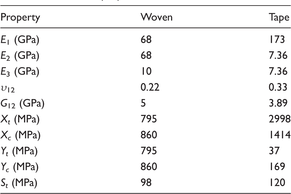
Two CFRP materials were tested in this study. The first material is bidirectional (woven) based on AS-4 carbon fiber and 8552-epoxy matrix. The total thickness was 2.2 mm and it was composed of 10 plies with the same orientation (direction 1 at 0°). The second material is a laminate composed by 24 unidirectional plies. It was manufactured from carbon IM7 fiber and MTM-45-1 epoxy resin and presented a quasi-isotropic lay-up with stacking sequence [45/−45/0/90]3S. The final thickness of each plate was approximately 3 mm.
Drill geometries and cutting parameters
Three different types of drill bits with nominal diameter equal to 6 mm were tested with both materials (see Figure 1): a Brad center drill, a new step drill with a length of step equal 6.6 cm and a section changing from 4 mm to 6 mm (the stepped geometries in the literature usually present a section change higher than 2 mm) and a Reamer drill with four cutting edges (a new geometry, not previously tested in the literature).
Geometries for Brad center drill (a), Step drill (b) and Reamer drill (c).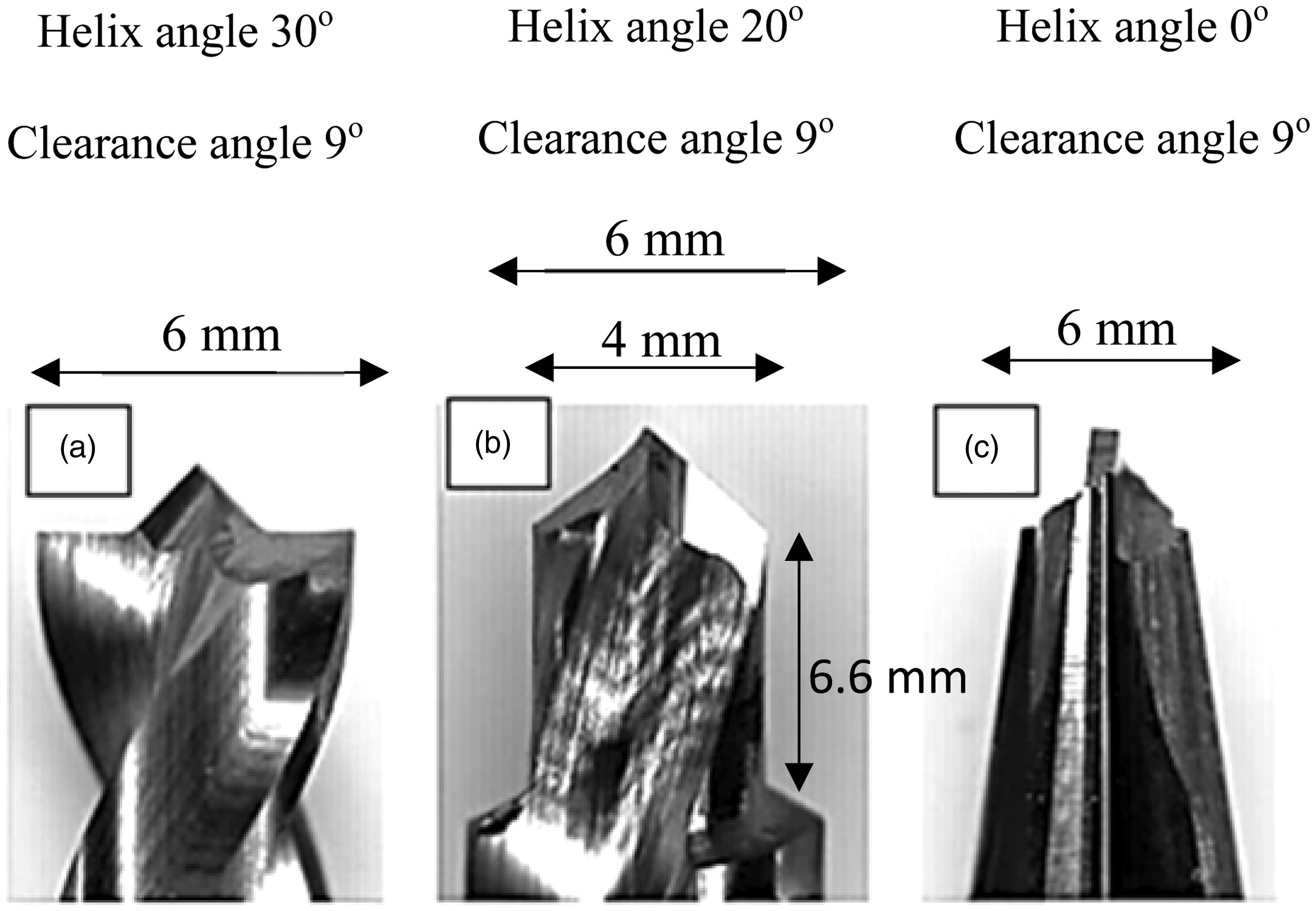
All drills, manufactured by Guhring, Inc., 36 were based on a CW substrate without coating and tested in fresh conditions in order to avoid the effect of wear evolution.
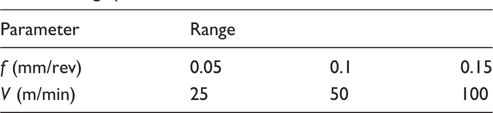
Cutting parameters used in drilling tests: f feed rate and V cutting speed.
Machine tool
A machining center B500 KONDIA, equipped with a Kistler 6123C rotating dynamometer was used for drilling tests and in process monitoring of the thrust force (Fy) and the torque (Mz) (Figure 2(a)).
(a) Experimental set-up and (b) measurement of diameters for calculation of delamination factor.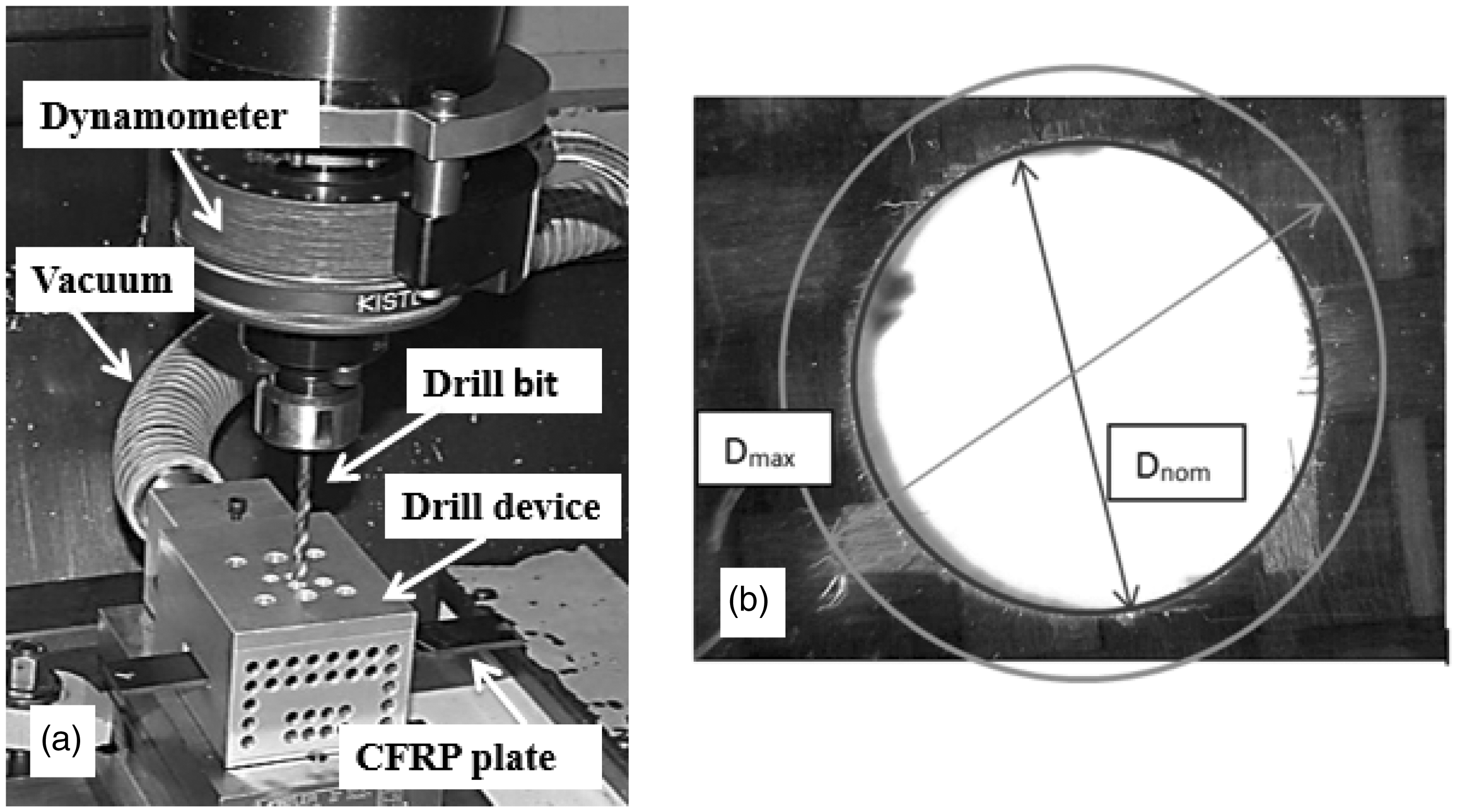
The composite was confined during drilling into a specially designed box connected to the vacuum in order to collect the chip avoiding the dispersion of the fibers into the environment or the contact with the machine and its operator.
Drilling tests were performed using a supporting back plate (previously drilled with a hole with a diameter close to the nominal diameter). This procedure, commonly used in industry, is expected to diminish delamination damage.
Delamination measurement
Delamination damage was quantified in terms of the delamination factor (Fd), defined as the ratio between the maximum diameter of delaminated area and the nominal diameter of the hole (see Figure 2(b)). Despite this factor does not account for the damaged area, it is the most used approach in the literature due to its simplicity. The hole quality was evaluated using an optical microscope (Optika SZR) in order to obtain the diameter of delaminated area. This measurement technique just considers the surface layers delamination where the damage area is externally exposed since the most critical damage modes are entry delamination (peel-up) and exit delamination (push out). Peel-up delamination is found around the hole entrance periphery as a consequence of the peeling force through the slope of the drill flutes, resulting in separation of the upper plies. On the other hand, push-out occurs due to the maximum thrust force reached when the tool tip breaks through the bottom face of the laminate, where the maximum delamination is usually originated. Thus, internal layers delamination was not accounted.
Results and discussion
Experimental results were evaluated in terms of cutting forces measured during drilling and delamination damage. The entrance and exit hole are critical zones usually exhibiting the largest delaminated area. When the cutting edges of drill bit make contact with the material, a peeling force through results in separating the upper plies from the laminate. This effect is remarkable when acute edges are used (corresponding to new unused tools). When edge wear progresses, this force is decreased since the geometry becomes to round. Wear progression elevates the thrust force but decreases the peel force thus leading to reduced peel-up and enhanced push-out delamination. 31
On the other hand, thrust force and torque depend on the drill geometry: both shape and magnitude are affected by the drill geometry.14,17 An example is given in the Figure 3, showing evolution of thrust force and torque with drill bit progress recorded during drilling tests of woven material (feed rate 0.1 mm/rev and cutting speed 100 m/min). Similar curves shape was obtained for the tape composite.
Evolution of thrust force and torque for the different geometries analyzed in case of woven material. Cutting conditions: f` = 0.1 mm/rev and V = 100 m/min.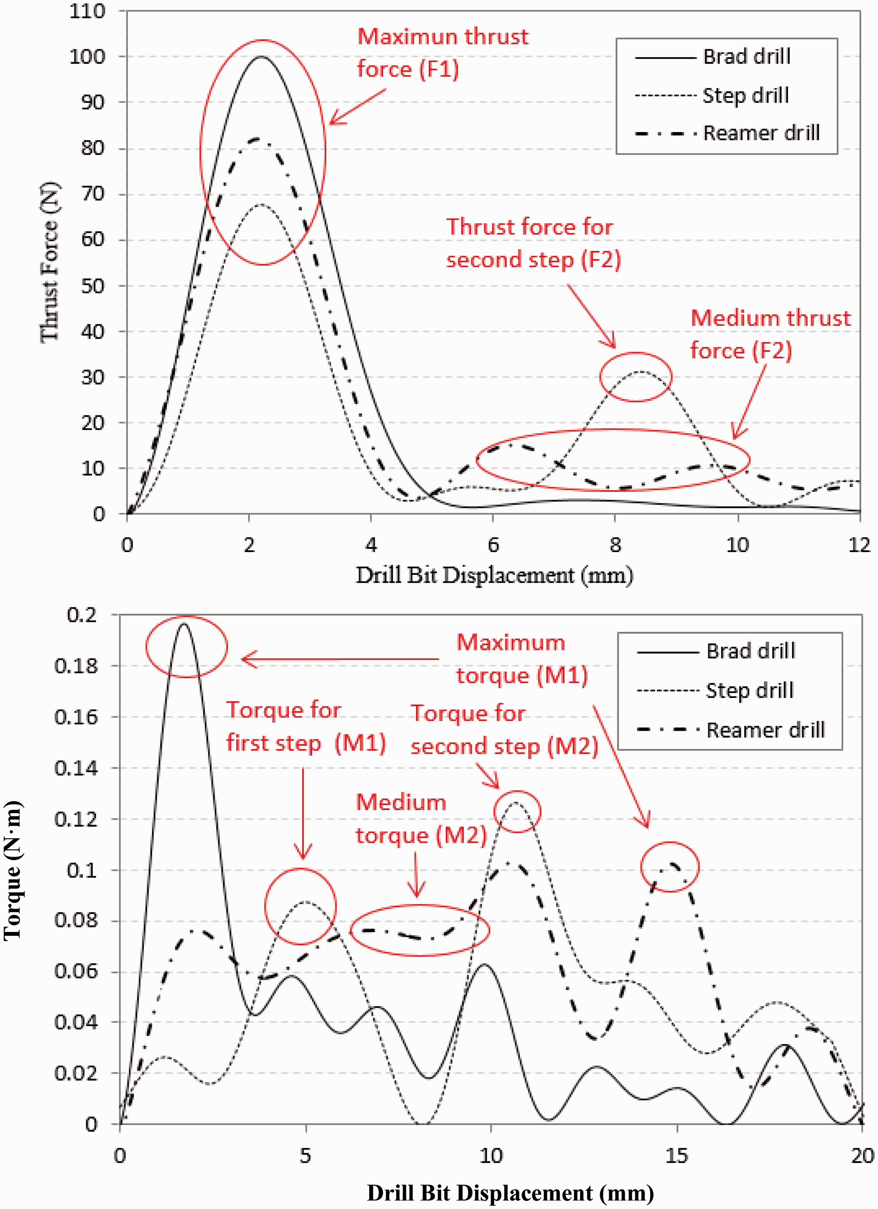
The graph corresponding to Brad drill clearly shows the point corresponding to the maximum thrust force and torque, both reached when the brad tip has penetrated completely across the laminate. The point angle of the drill (180°) leads to a rapid increase of the forces and the maximum is reached very fast.
When step drill is considered, two peaks indicate the maximum level of thrust and torque corresponding to both steps of the drill. The first one is due to the effect of the point of the drill bit (F1 and T1) and the second one is due to the action of the second step (F2 and T2).
Finally, the evolution obtained with the Reamer drill shows a first peak in the thrust force (corresponding to the entrance of conical part of the drill) followed by a plateau, and this zone corresponds with the maximum value of the torque (appearing when the cylindrical part of the drill is cutting). The absolute level of thrust force presents the lowest values for the step drill. The reamer and brad drill showed similar values of maximum thrust force, slightly higher for brad drill.
Woven composite
Thrust force and torque
Figure 4 shows the level of the significant values of thrust force and torque defined in the previous section under the different cutting conditions tested for each drill geometry.
Variation of thrust force versus feed rate for Brad drill (a), Step drill (c) and Reamer drill (e) and torque versus feed rate for Brad drill (b), Step drill (d) and Reamer drill (f) for woven material.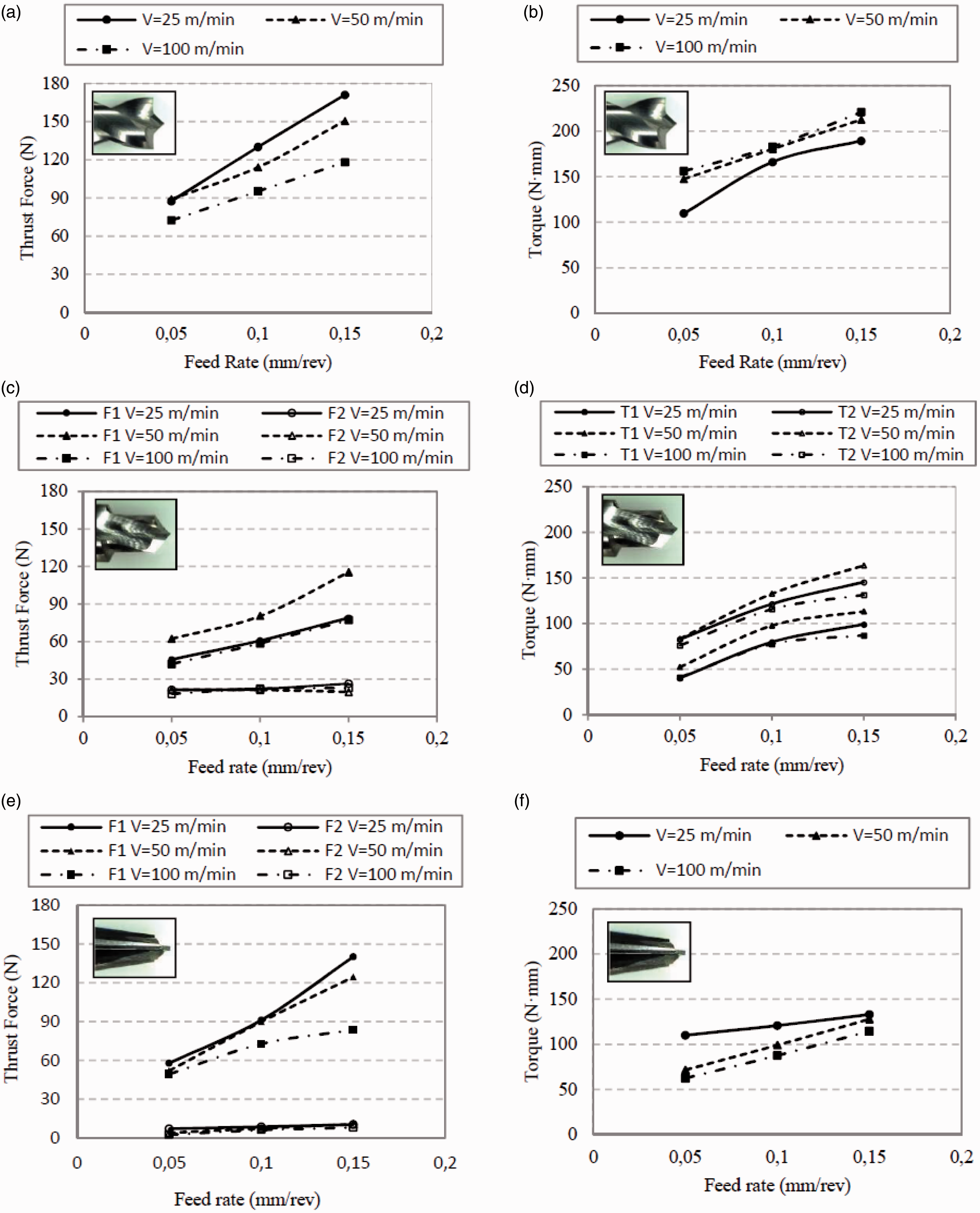
In all cases, the maximum level of thrust force increased (F1) with feed rate; however, for step drill and Reamer drill, the effective medium force (denoted F2 in Figure 4(c) and (e)) showed negligible influence of cutting conditions. This fact was also verified in previous works.25,26 On the other hand, Brad drill led to increased thrust force with feed rate (up to 92%).
Spindle speed had an opposite effect and in general thrust force decreased with cutting speed (up to 45%). The brad drill bit registered the maximum thrust forces while the lowest values were found for Reamer drill.
Torque analysis increased with feed rate for all cases (Figure 4(b), (d), (f)). Variations up to 63%, 96% and 84% were observed for Brad drill, step drill and reamer drill, respectively. However, cutting speed presented different effect in function of the geometry; Brad drill had a positive growing while Reamer has a negative trending. Also minimum torque was found for Reamer drill whereas the highest values were observed for Brad drill.
Delamination
Figure 5 shows delamination factor calculated both at entry and exit hole for woven material. Maximum entry delamination increased up to 10% for the case of Brad drill and 18% for the Reamer drill when feed rate increases. Step drill did not present significant variation. Concerning the influence of cutting speed, peel-up extension increased for Brad and step drill (8% and 4%). The opposite trend was observed for Reamer drill: entrance delamination decreased with the spindle speed up to 15%.
Delamination factor versus feed rate for Brad drill (a, d), Step drill (b, e) and Reamer drill (c, f) for woven material.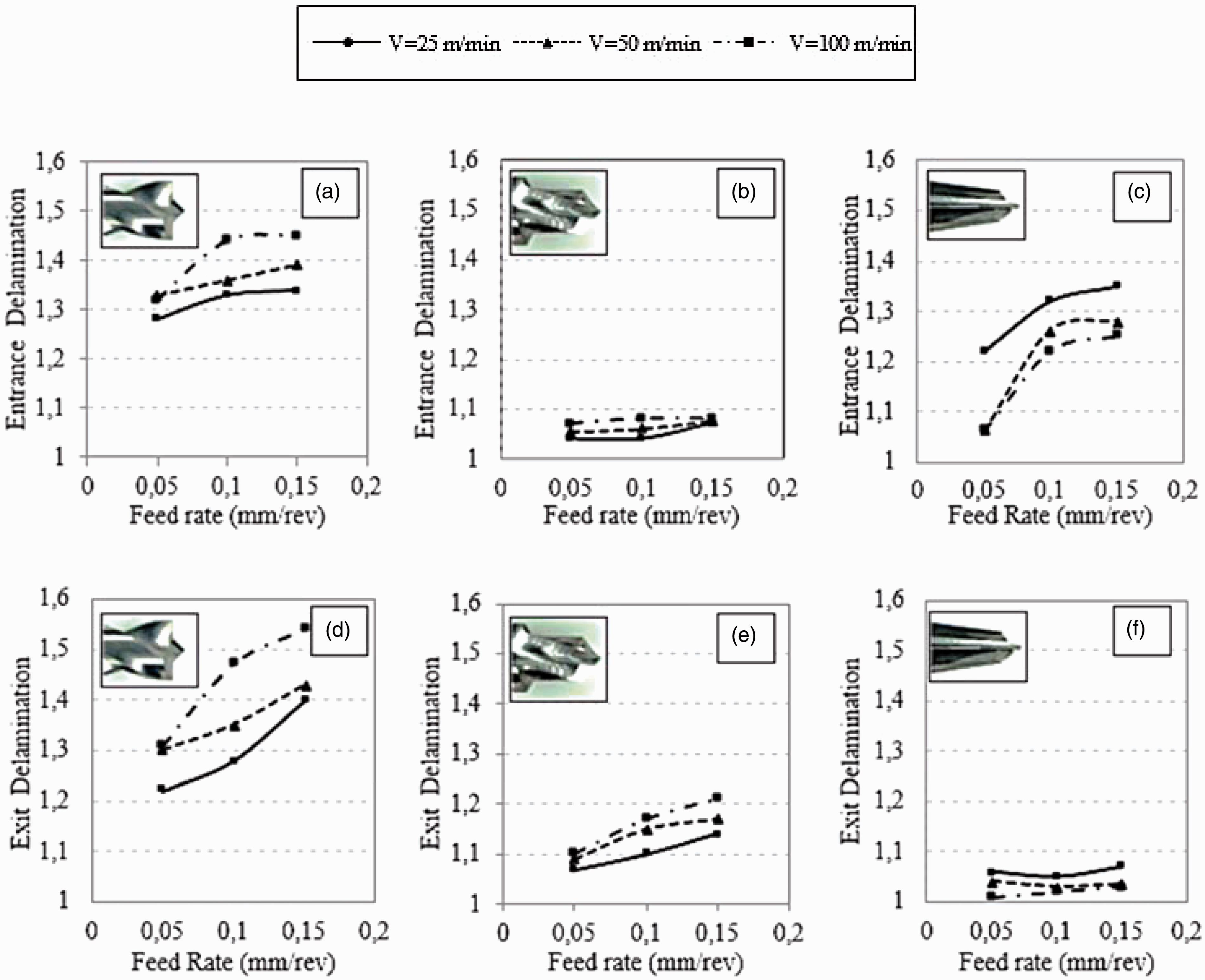
Exit delamination increased up to 17.5% for Brad drill and 10% for step drill with feed rate, while reamer drill showed negligible variation with feed rate. Exit delamination increased with cutting speed for Brad drill and step drill (up to 10 % and 6%, respectively) while it was decreased up to 3% for Reamer drill.
Comparing the effect of drill geometry, the lowest entry delamination was obtained with the step drill (Fd = 1.04) and the highest with Brad drill (Fd = 1.45). The most beneficial configuration seems to be the step drill, probably due to the multistep drill.
In the case of exit delamination, the lowest extension of this defect was observed for Reamer drill (Fd = 1.01) and the highest for Brad drill (Fd = 1.54). Exit delamination is related to thrust force and hole configuration. In the case of brad drill, exhibiting the highest value of trust force, it is also observed the highest value of delamination factor at the hole exit. Although reamer and step drill presented similar level of trust force, it is observed smaller extension of delamination for reamer drill. This effect could be related to the multistep configuration of the step drill, the final hole is machined on a previous hole made with the tip of the drill. The ability to resist delamination at the interface is lower than in the case of reamer drill, machining the intact plate of composite.
Multidirectional composite
Thrust force and torque
The evolution of cutting forces with cutting time for the tape composite showed similar trends than those obtained for the woven material. Thrust force increased with feed rate for all geometries analyzed (see Figure 6). The increment of effective force (F2 in the case of step and Reamer drills) was around 112% for Brad drill, 18% for step drill and a 90% for Reamer drill. Cutting speed variation did not induce significant changes in the thrust force at low feed rates. However, when spindle speed increased the influence was enhanced, especially in the case of Brad drill: thrust force reduction around 20% was observed.
Variation of thrust force versus feed rate for Brad drill (a), Step drill (c) and Reamer drill (e) and torque versus feed rate for Brad drill (b), Step drill (d) and Reamer drill (f) for tape material.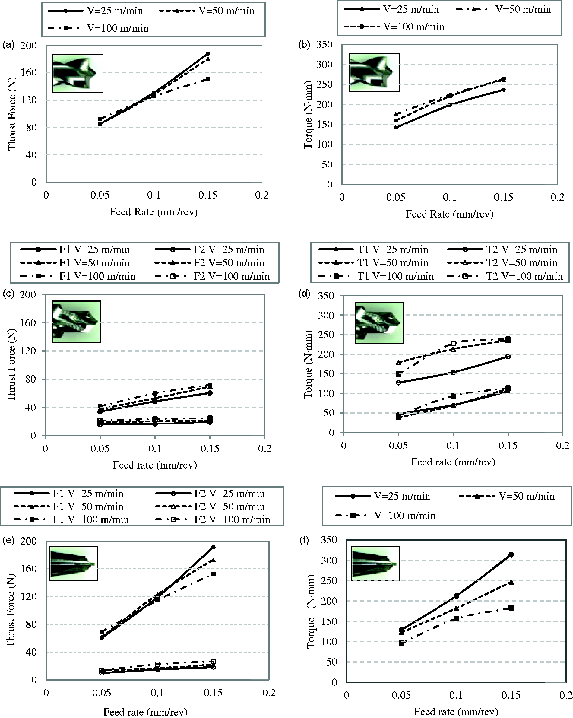
The maximum level of thrust force presented the lowest values for the step drill. The reamer and brad drill showed similar values of maximum thrust force. This behavior is in agreement with previous work in the literature. 14
Torque increased with feed rate up to 66% for Brad drill, a 60% for step drill and a 144% for Reamer drill. Enhanced cutting speed led to increased torque in the case of Brad drill (24%) and step drill (48%) while for Reamer drill involved torque decrease (72%).
Delamination
Delamination factor measured for the three geometries is presented in Figure 7. In general the increase of feed rate lead to enhanced delamination. Peel up delamination factor was increased up to 24% for Brad drill. Step drill showed a maximum in delamination for the intermediate value of the cutting speed (50 m/min) and for the highest value of velocity the delamination factor decreases again. Entry delamination increased with cutting speed up to 8% for Brad drill and 5% for step drill. Reamer drill did not show influence of cutting speed in the case of entry delamination.
Delamination factor versus feed rate for Brad drill (a, d), Step drill (b, e) and Reamer drill (c, f) for tape material.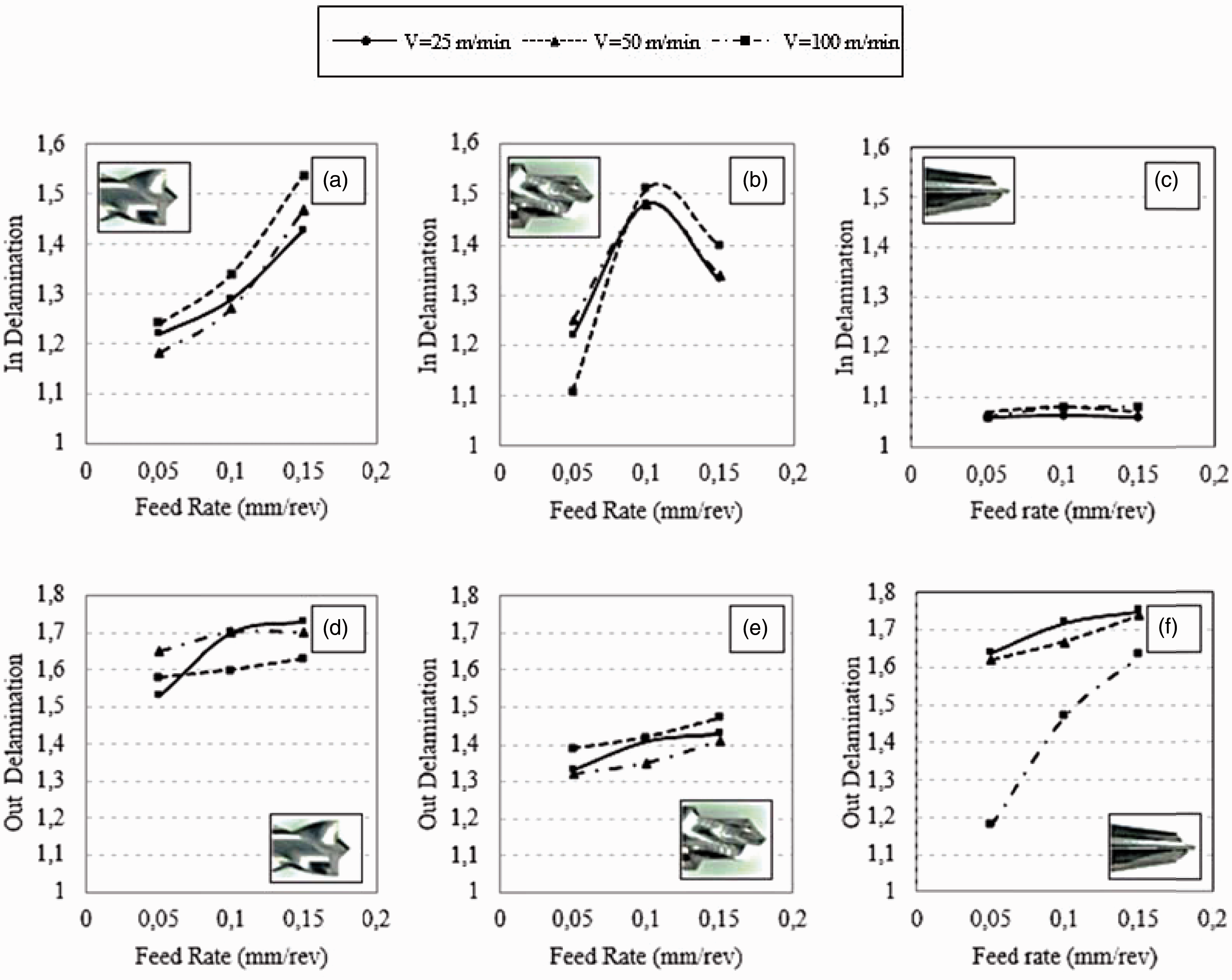
Exit delamination increased with feed rate up to 11%, 6% and 38% for Brad drill, step drill and Reamer drill, respectively. Variations with cutting speed were small for the brad and step drill (lower than 8%) while delamination factor increased up to 37% for Reamer drill.
The maximum entry delamination extension was found for Brad drill (Fd = 1.54) while the minimum was obtained with Reamer drill (Fd = 1.08). Concerning exit delamination, Brad drill showed the worst results (Fd = 1.73) and step drill the best (Fd = 1.32). This is mainly due to the low thrust force of the step drill in the last ply for this kind of materials. 14 However, when drilling with low feed rate reamer drill improved the step drill results (Fd = 1.18) in agreement with results provided in the literature. 14
Comparison between woven and multidirectional composites
Thrust force and delamination
Trust force obtained when drilling woven and multidirectional composite are not directly comparable because the thickness of the laminates are not the same (the woven composite was 2.2 mm thick and the multidirectional composite was 3 mm thick). In order to compare both materials, the forces have been normalized with the thickness of the material. The general trend was that thrust forces were higher for woven material than for tape material (see Figure 8(a) showing an example). This behavior is related to the enhanced mechanical properties of the woven composite involving superior breakage energy.
Variation of thrust force (a) and exit delamination (b) for Brad drill. Cutting speed: 100 m/min.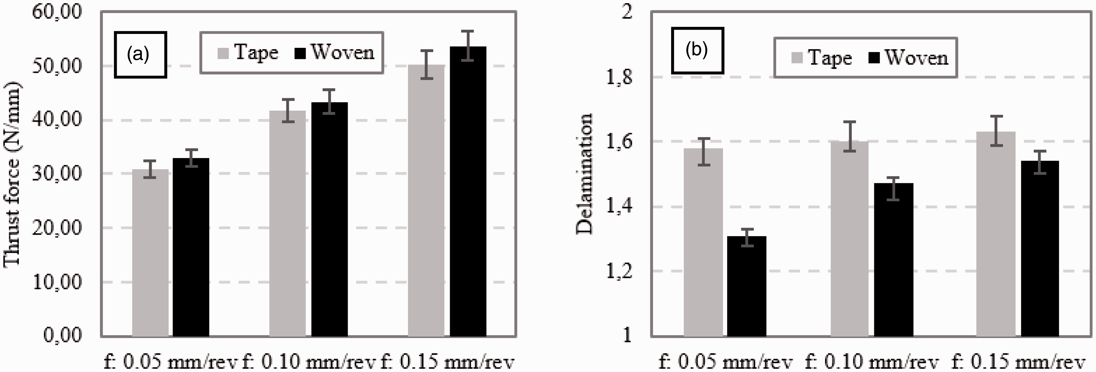
On the other hand, delamination extension found for unidirectional material is in most cases higher than that observed for woven material. Woven structure gives a clear advantage when drilling induced delamination should be minimized: although higher forces are required to perforate the material, at the same time separation between plies is more difficult. An example of this behavior is provided in Figure 8(b) where thrust force and exit delamination have been presented for Brad drill comparing both types of composites. Similar conclusions for the case of step drill were presented in previous work. 26
ANOVA analysis
An ANOVA analysis using the software StatGraphics software has been developed for each geometry and material in order to study the influence and contribution of the input variables (feed rate, cutting speed) on the output variables (thrust force, torque and delamination factor at the entrance and the exit hole).
Comparison of ANOVA analysis for thrust force, torque, peel-up and push-out between woven and tape materials for Brad drill bit.
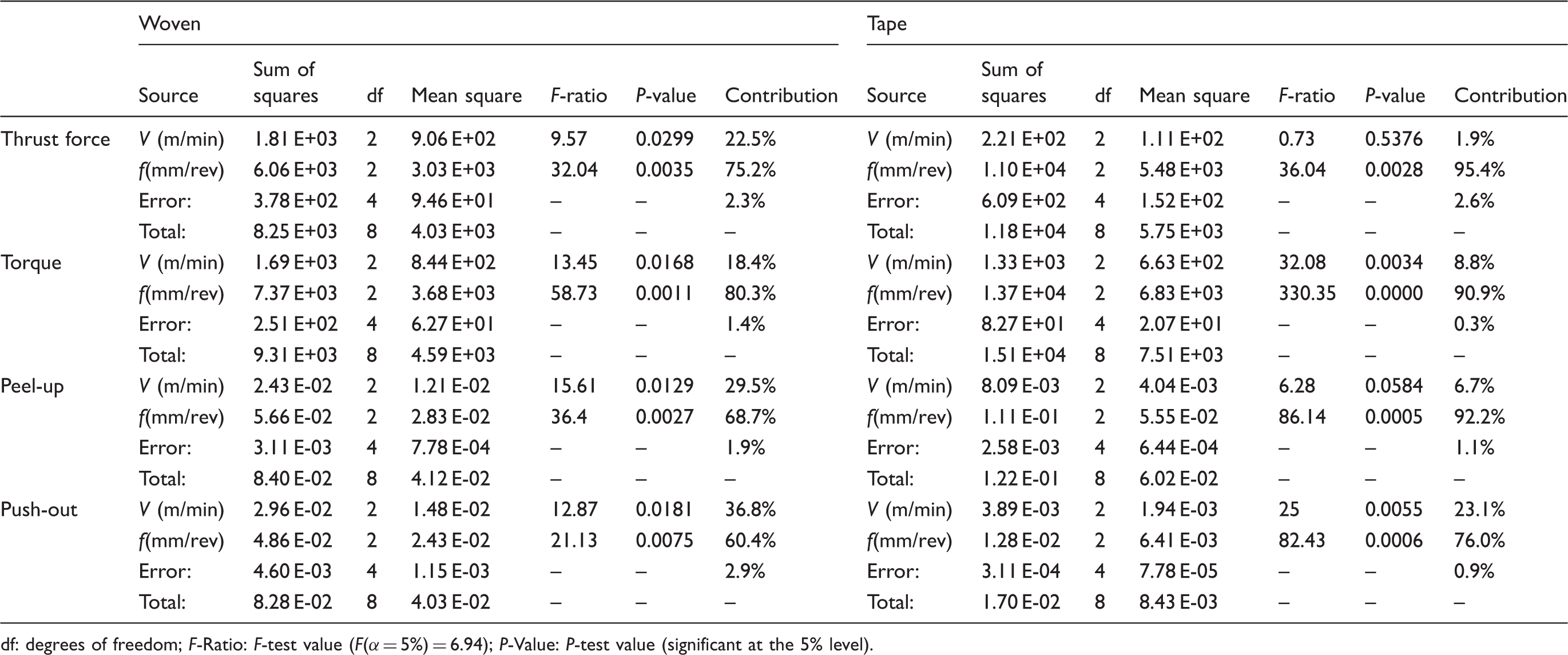
df: degrees of freedom; F-Ratio: F-test value (F(α = 5%) = 6.94); P-Value: P-test value (significant at the 5% level).
Comparison of ANOVA analysis for thrust force, torque, peel-up and push-out between woven and tape materials for Step drill bit.
df: degrees of freedom; F-ratio: F-test value (F(α = 5%) = 6.94); P-Value: P-test value (significant at the 5% level).
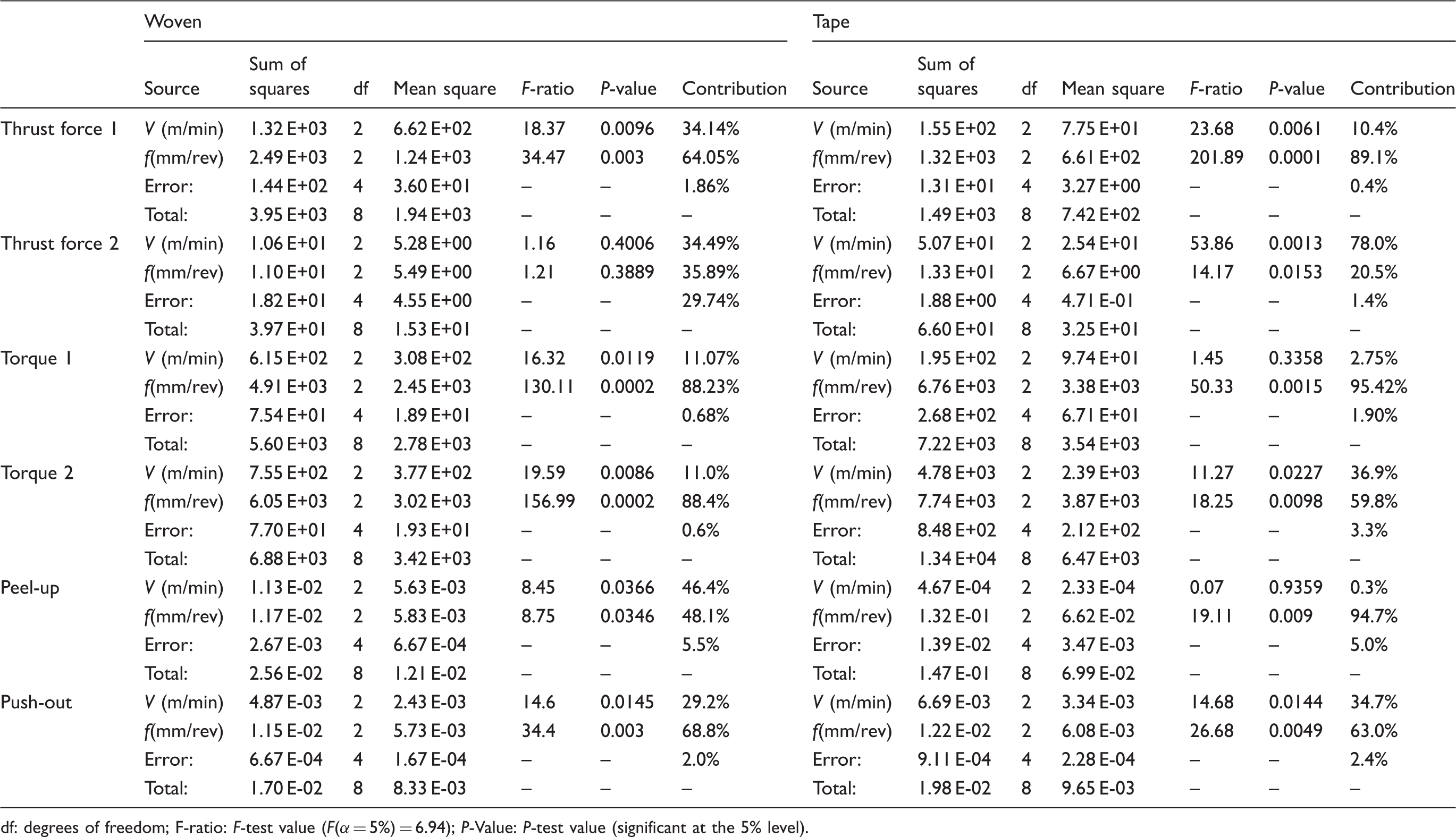
Comparison of ANOVA analysis for thrust force, torque, peel-up and push-out between woven and tape materials for Reamer drill bit.
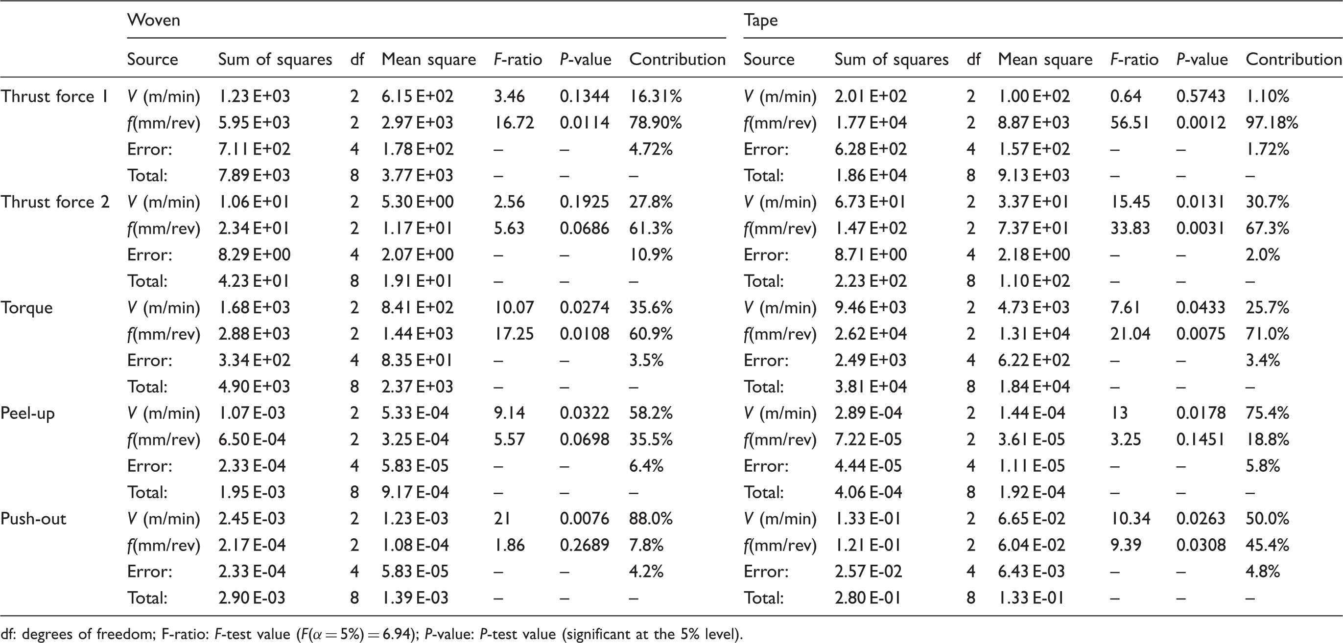
df: degrees of freedom; F-ratio: F-test value (F(α = 5%) = 6.94); P-value: P-test value (significant at the 5% level).
The case for tape material is similar to previous drills. Both parameters are influent on the outputs (F-ratio>6.94, P-value<0.05) except for peel-up, where only cutting speed is significant. It is relevant that cutting speed has also high contribution in push-out (50%) in contrast to the other two drill bits for which the influence of the cutting speed in delamination is between 23% and 30%.
Other surface defects
Finally, comparing other superficial defects observed after drilling both materials are commented in this section. Tape material is more vulnerable to damage: surface quality is always inferior for the tape composite than for the woven laminate for any of the selected geometries (Figure 9). Fraying defect is found for all cases: Reamer and step drills present this defect especially at the exit and Brad drill at the entrance.
Delamination damage and other defects in multidirectional material for the three different drill geometries (V = 100 m/min, f = 0.1 mm/rev).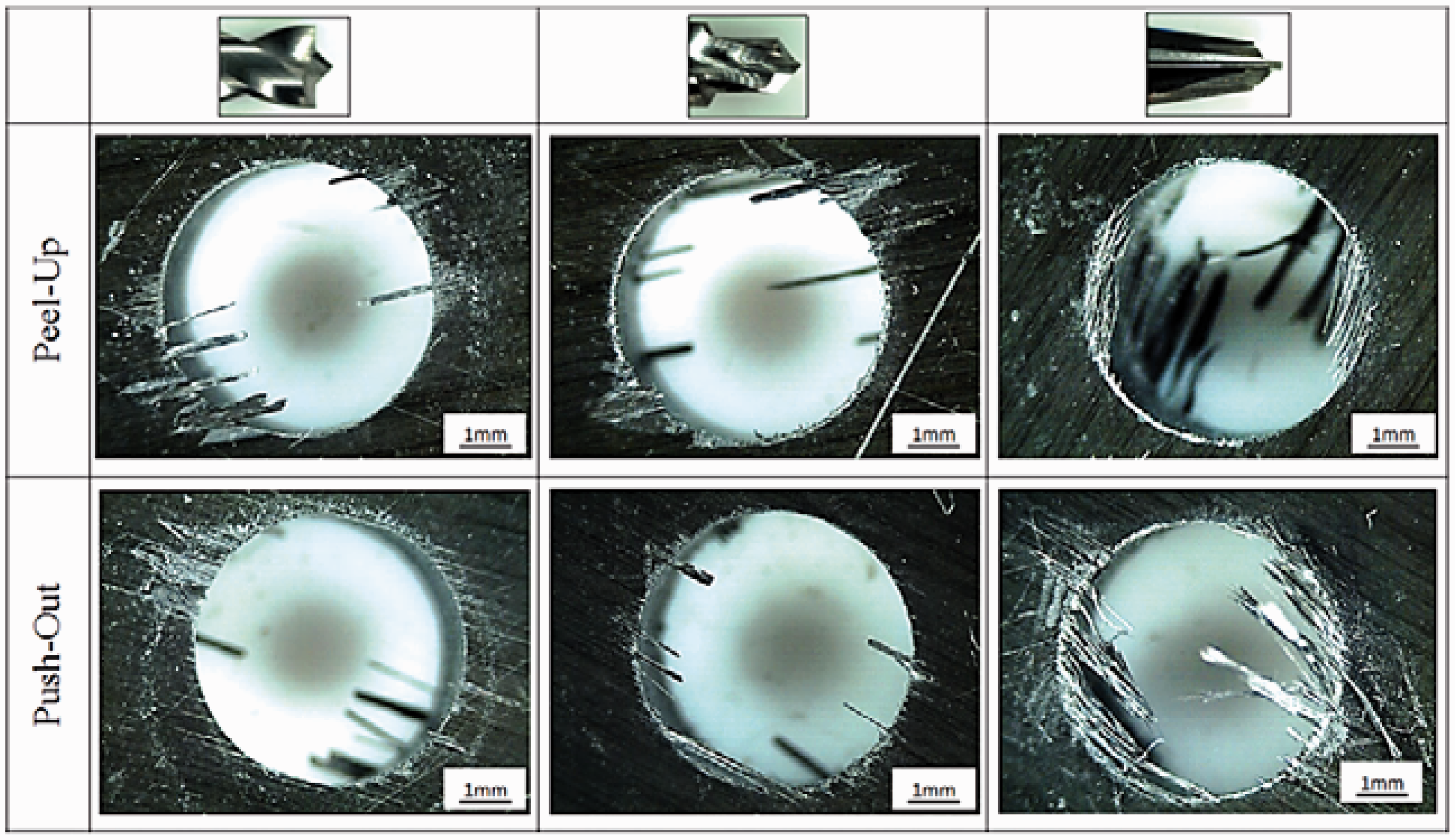
On the other hand, fraying area found in woven material was very small (Figure 10). Only step geometry caused some chipping at the entrance and exit hole. In Figure 10, it can be observed also that surface quality for Reamer drill bit is the best in both sides of the hole.
Delamination damage in woven material for the three different drill geometries (V = 100 m/min, f = 0.1 mm/rev).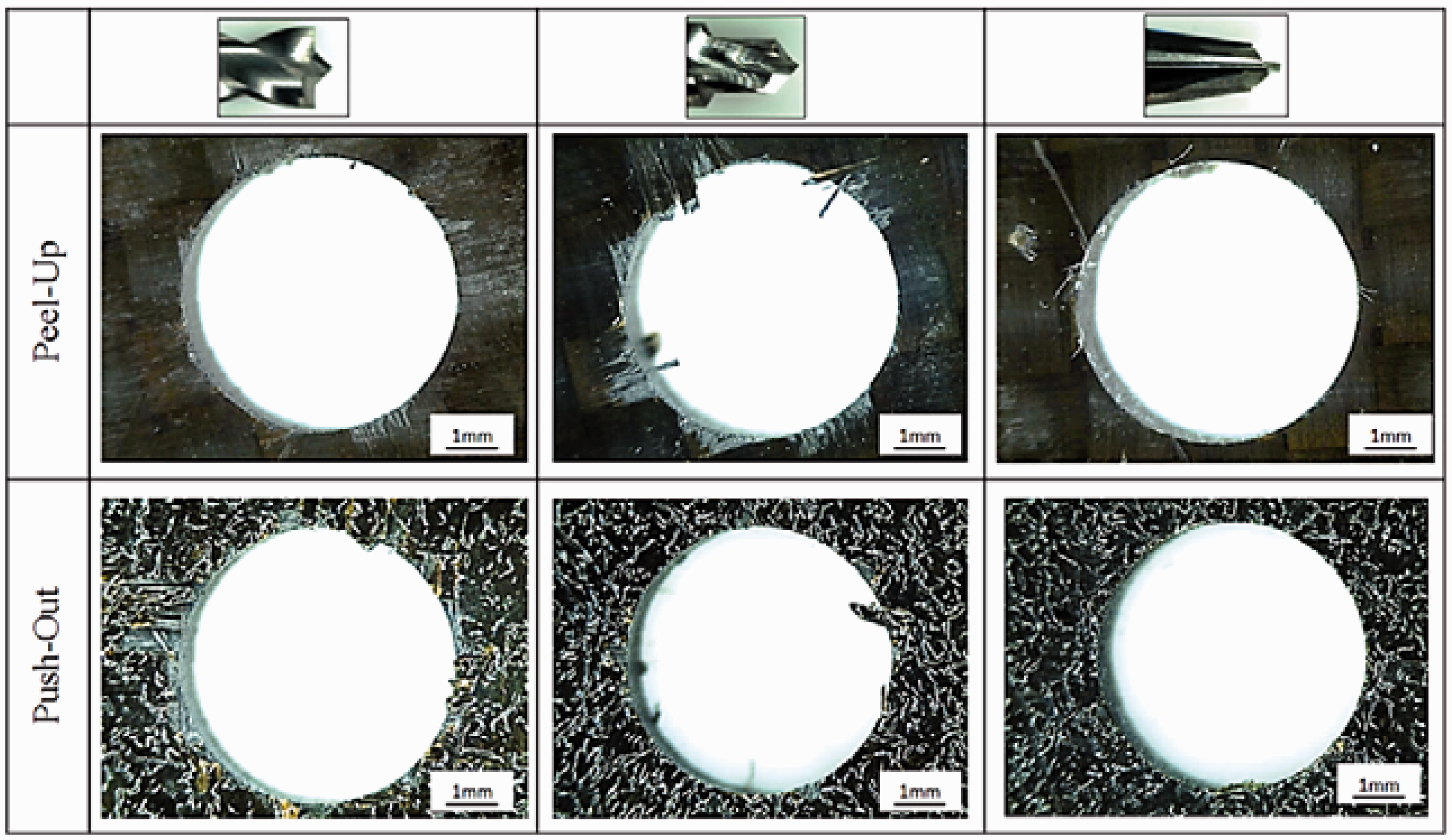
Tool wear evolution
Analyzing the experimental results for exit delamination, the minimum damage working with the most productive cutting parameters (f = 0.15 mm/rev and V = 100 m/min) were given by the reamer drill in the case of woven material and the step drill in the case of tape material.
There is not a general criterion indicating that the end of tool life is reached. Adherence of resins and fibers to cutting edges, enhanced sound and vibration and even resin burning are phenomena indicating excessive wear of the drill. In this case, to observe the wear evolution and its influence in the delamination damage, a total of 60 holes were machined with both drills. Despite the elevated number of holes machined and the abrasion of carbon fibers, the wear did not present a rapid evolution.
Figures 11 and 12 show the evolution of delamination factor versus the number of drilled holes for both cases analyzed. The increment of the damage extension is slower at the hole exit than at the entrance in the case of woven composite. Peel-up increases considerably after drilling 40 holes. Chipping and spalling defects can be also appreciated at the entry of the hole (Figure 9) decreasing the surface quality.
Entry and exit delamination for woven material vs. number of drill holes. Entry and exit delamination for multidirectional material vs. number of drill holes.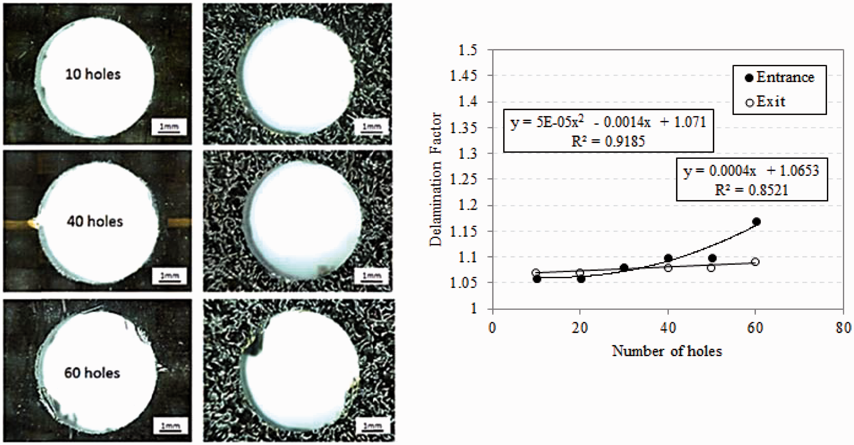
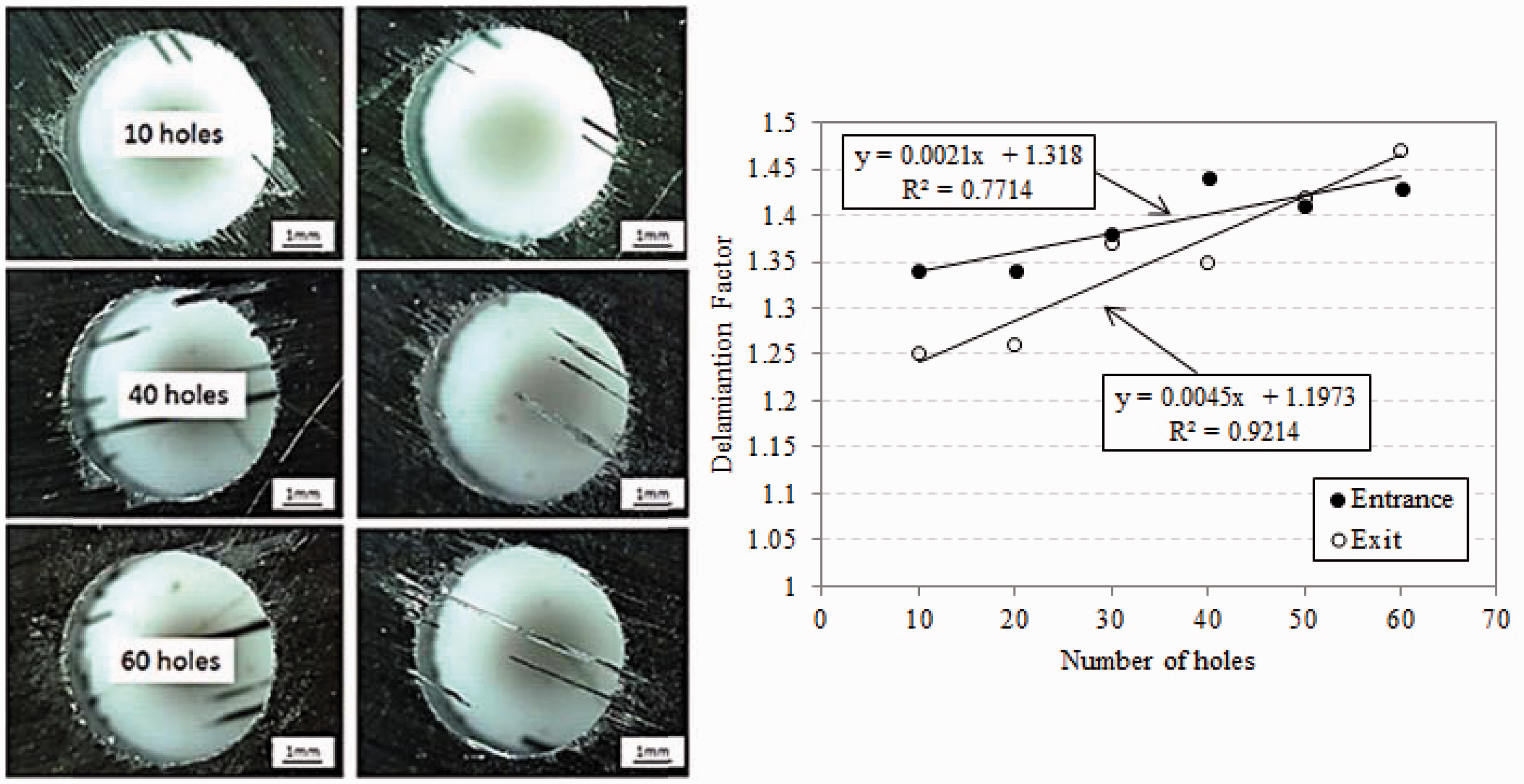
For the multidirectional composite, delamination increases for both entrace and exit delamination (Figure 10). The increment is aproximately lineal and for low number of drill holes peel up is larger than push out. On the other hand, fraying can be observed in both sides of the hole, being lower at the entrance. The fraying at exit increases with the number of holes and the length of threads is longer.
It is worth noting that the drills seem to be almost intact for the number of holes machined; however, the quality of the hole became poor as the number of holes machined with the drill increased. The observation of the tool gives minor information about the end of tool criterion. The evolution of hole quality as wear progresses should be accounted in order to establish the end of tool life criterion leading to drill replacement.
Conclusions
In this paper, the influence of different drill geometries in drilling both tape and woven composite has been analyzed. The geometries selected are based in recent designs of the tool manufacturer especially in the case of Reamer drill bit.
Some conclusions concerning the behavior of different geometries tested in this study are summarized below.
It was shown that Reamer drill is the most adequate geometry for drilling woven materials (between the geometries analyzed in the work) with low feed rate and high cutting speed. The torque and thrust force obtained are the lowest and delamination extension is small (between 1.01 and 1.08). For this tool the influence of cutting parameters in thrust force is low. Reamer drill could be also recommended for tape material, working with low feed rate and high cutting speed. In this case, the cutting speed is important due to the influence of this parameter in delamination is high. The range of delamination factor is in the range 1.06–1.18. However, in this case, the occurrence of other surface defects such as fraying is severe. Brad drill presented the highest thrust forces and consequently the worst surface quality.
Concerning the influence of the laminate configuration, it can be concluded that tape material is more susceptible to suffer delamination damage, experiencing stronger delamination although thrust forces were lower. Fraying defect was observed for all drill holes. The superficial quality showed for woven is always superior for all conditions analyzed.
This is an important conclusion of the work: woven composite not only exhibits enhanced mechanical properties, as it is well known, but also presents better surface quality when drilled.
Concerning the influence of cutting parameters, the ANOVA analysis showed that the most influential parameter on thrust force and torque is in general feed rate. However, cutting speed is not negligible in many cases and its influence depends on the drill geometry. For the special case of Reamer drill bit, the ANOVA showed that feed rate has no influence on delamination damage while cutting speed has an important contribution (between 50% and 88%).
Finally, it has been proved that wear has an important impact on the final quality of the hole. In the case of woven material, Reamer drill presented proper behavior when the drill bit is new leading to reduced delamination. As wear progresses, the entry damage increases quickly. However, in the case of tape composite, step drill shows similar growing trend for both entry and exit delamination. The establishment of the end of tool life criterion should be done accounting for the final quality of the hole, in terms of maximum number of holes machined with the drill.
Footnotes
Declaration of Conflicting Interests
The author(s) declared no potential conflicts of interest with respect to the research, authorship, and/or publication of this article.
Funding
The author(s) disclosed receipt of the following financial support for the research, authorship, and/or publication of this article: This work was supported by the Ministry of Economy and Competitiveness of Spain (DPI2011-25999) and the FPI subprogram (BES-2012-055162).