
Abstract
The non-linear deformation response of plain woven carbon fiber-reinforced composites is experimentally studied at meso-scales. Stereovision digital image correlation is utilized to capture the full-field strain distribution over a 10 × 10 mm2 area of interest located at the center of the specimens. The evolution of local strains on the fiber bundles and matrix-rich regions as a function of loading is extracted. The effect of fiber orientation angle on fiber bundles stretch ratio and their angle of rotation (fiber trellising) and the related underlying failure mechanisms are analyzed using the measured full-field displacement data. The results indicate that the local load-bearing mechanisms are different in on-axis and off-axis loading conditions, whereas the larger global failure strain noticed in off-axis conditions is attributed to the occurrence of fiber rotation. The fiber trellising is also shown to promote high local shear strain and consequently leads to the protrusion of the matrix material on the deformed specimen surface.
Introduction
It is well established that fiber composites exhibit non-linear stress–strain response under off-axis loading. This non-linearity is often observed in the global tensile stress–strain curves of off-axis specimens and is the consequence of complex load-bearing mechanisms resulted from interactions between the reinforcing fibers and the matrix. 1 It is also understood that the global mechanical response of off-axis fiber composites has a strong sensitivity to the angle between the loading direction and the orientation of the fibers. The fiber orientation angle affects the degree of the non-linearity in the constitutive response of the composite.2–4
Although detailed studies of micro- and macroscopic behavior of fiber composites are currently available in the literature, there are only few studies dealing with the meso-scale response of fiber composites, particularly from the experimental perspective.5–12 These experimental-base investigations have generally been carried out in a more qualitative sense to understand the yarn interaction mechanisms,9,10 the nature of deformation inhomogeneity in fiber composites,5,12 detection of damage initiation, 11 to provide correlation between the macro-scale deformation and failure response to the meso-scale behavior of the material, 7 and to validate finite element (FE) simulations. 6 It is interesting to note that the application of digital image correlation (DIC) is the common method in the majority of the research conducted in the fields of meso-scale deformation and damage response studies in woven composites. This is due to the capability of this technique to capture accurate full-field deformation response of materials, as well as the availability of plug-and-play commercial systems. 13 This powerful optical technique has been successfully practiced in the deformation and failure analyses of fiber composites at a wide range of time and length scales.14,15
A more detailed survey in the available literature on woven fiber composites reveals that the local deformation mechanisms, as well as the origin of the non-linear deformation response are not yet well understood. The underlying mechanisms behind this orientation dependence are believed to be due to the occurrence of fiber trellising mechanism in the off-axis specimens subjected to in-plane tension. 8 Fiber trellising has so far only been investigated either at macroscales or through the use of complex finite element analyses. However, fiber trellising is a local mechanism and no evidence on the meso-scale experimental study of this phenomenon is found in the literature. In light of this, the present work attempts to experimentally study the meso-scale deformation response of a plain woven carbon fiber-reinforced composite and to provide quantitative information on the nature of deformation non-linearity in tensile behavior of off-axis composite specimens. In this regard, stereovision 3D DIC was utilized to capture full-field strain maps at submillimeter length scales. Theoretically, for flat samples loaded in-plane, the use of a single camera system and 2D DIC are sufficient. However, the accuracy of 2D DIC is highly affected by the out-of-plane deformation. The use of 3D DIC has been established to allow for a substantially more accurate evaluation of the full-field displacement and strain distributions, particularly when significant out-of-plane displacement is present within the field of interest. 16 The presence of such out-of-plane motions was confirmed in this study as a direct result of fiber trellising, which causes the protrusion of soft matrix material on the surface of the specimen. Hence, 3D DIC is successfully implemented in this work, and the principal mechanisms behind the non-linear response of off-axis woven composite specimens, i.e. fiber trellising and individual fiber bundle stretch were studied. The authors strongly believe that the current research is the first of its kind to deal with a detailed study of underlying mechanisms in the fiber trellising phenomenon from an experimental perspective.
Experimental
Material and specimen geometry
Quasi-static tensile experiments were conducted on three-layer orthogonally woven carbon fiber-reinforced composite sheets of 0.8 mm thickness. The composite contains approximately 70 vol.% carbon fibers. Carbon fibers of ∼7 µm in diameter are processed into tows interwoven to a plain weave fabric, forming unit cells of ∼1.8 × 1.8 mm2 dimensions. Further details on the properties of the composite specimens used in the present work can be found elsewhere.
3
Rectangular specimens of 25 mm wide and 175 mm long were cut out of the as-received composite sheet in directions of β = 0°, 15°, 30° and 45°, measured from the vertical principal direction, as shown in Figure 1(a). The grip length was 25 mm at both specimen ends, resulting in a gage length of 125 mm. Specimens were inserted into the tensile machine with their grip length held inside the hydraulic grips. To protect against the damage caused by serrated steel grips, 2 mm thick aluminum tabs were epoxied on the grip section at both ends of the tensile specimens, as shown in Figure 1(b).
(a) Schematic view of the off-axis tensile specimens. An actual tensile specimen is illustrated in (b) and the typical speckle pattern applied on the specimen center can be seen in (c).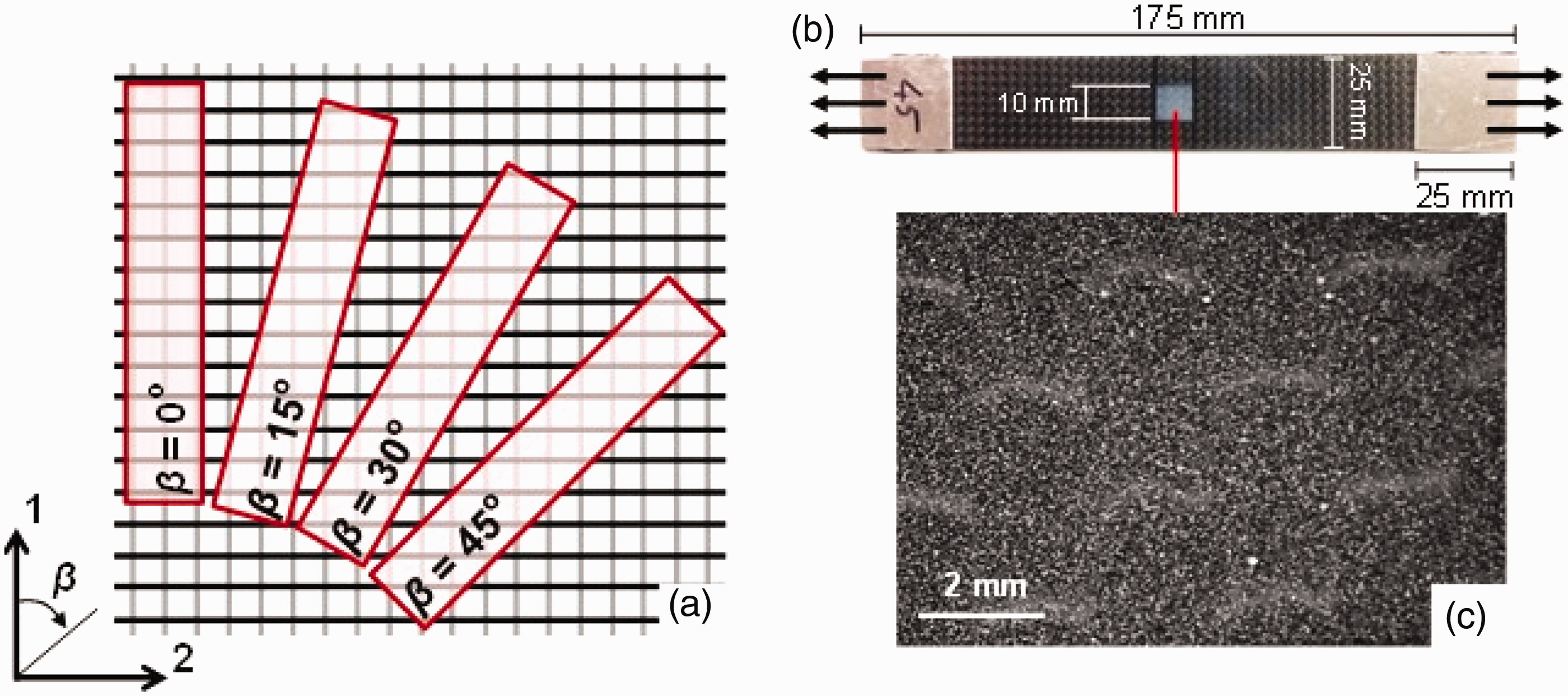
Tensile experiments and DIC
Tensile tests were performed using a 250 kN MTS machine in displacement control mode at a rate of 1.5 mm/min, which is equivalent to a mean strain rate of 2 × 10⁻⁴ s−1. Load and cross-head displacement data were acquired from the load-cell and displacement sensors of the tensile frame, respectively, while their sampling rates were synchronized with the framing rate of the cameras used for the image correlation purpose.
3D DIC was used to study the full-field deformation response of specimens at meso-scales. A high-contrast, random and isotropic speckle pattern is required to extract full-field deformation response using DIC. Taking advantage of the natural black color of the specimens, white speckle patterns containing ∼20 µm randomly distributed dots were applied on a 10 × 10 mm2 area at the center of each specimen using an air brush and a diluted flat white paint (see Figure 1(b) and (c).
A stereovision camera system containing a pair of 5 MP CCD cameras, each equipped with a high-magnification 100 mm macro lens was used to capture stereo images of the speckled area during loading. In the case of stereovision 3D DIC, the out-of-plane motion will not have any significant contribution to the in-plane deformation measurement and hence, the accuracy of the in-plane strain measurements will be substantially improved.
16
The camera system was calibrated prior to the tensile experiments using 6 × 6 mm2 calibration plates.
17
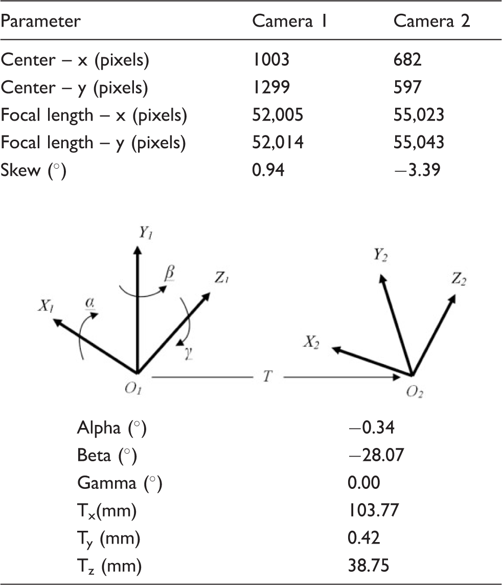
External illumination containing high-intensity LED white light source was used to promote uniform illumination of the specimen in the region of interest. Figure 2 depicts the experimental setup used in this work. Calibration details of the stereovision system are listed in Table 1.
The experimental setup utilized to capture meso-scale deformation response of the specimens in this work. System parameters obtained from calibration of the stereo camera arrangements.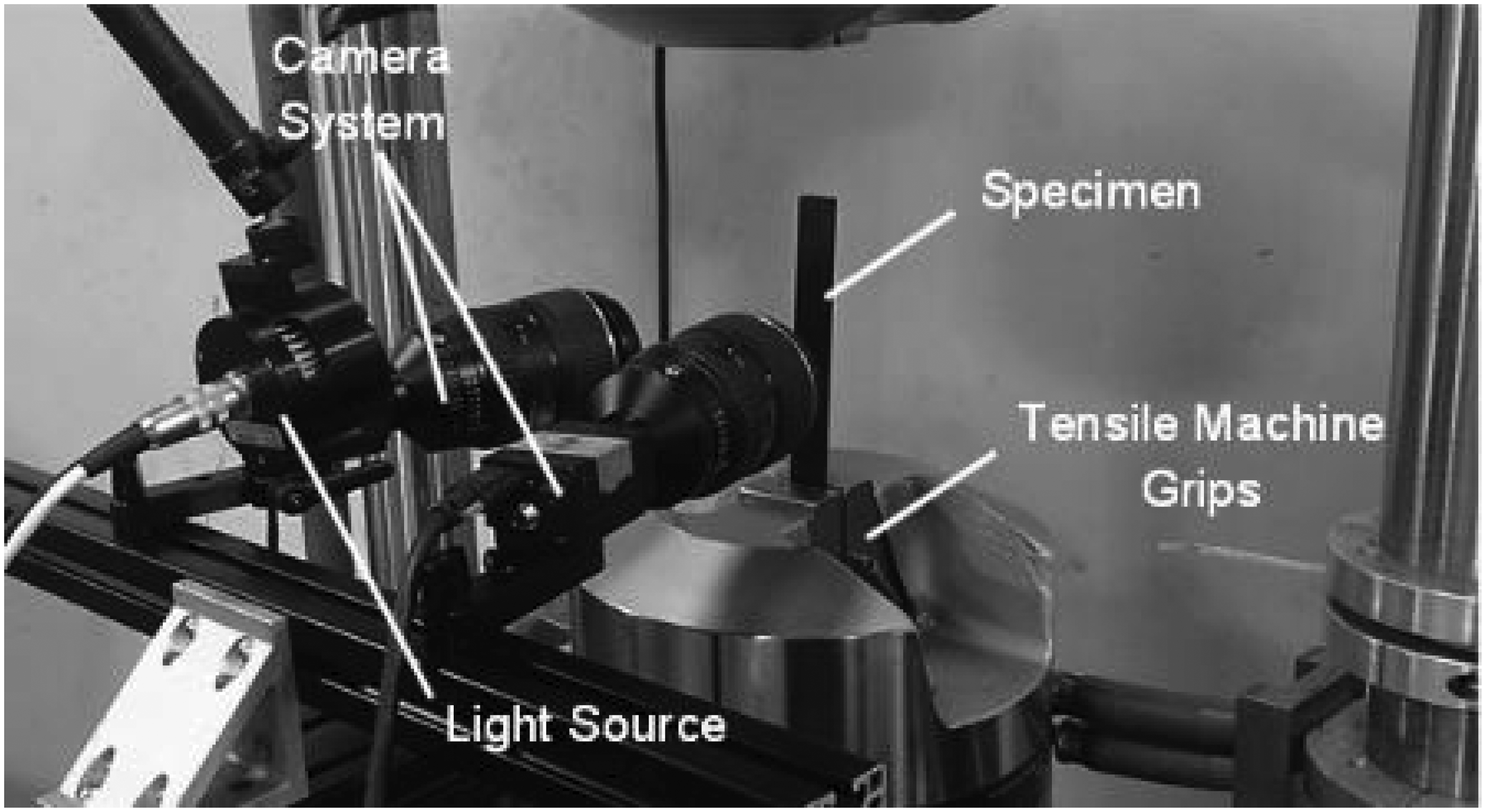
Images from the speckled region were taken during tensile loading at full-field resolution of 2448 × 2048 pix2 and at a rate of 1 fps. Images acquired during the tensile experiments were used to extract the displacement and strain fields using commercial DIC software Vic-3D. 17 In this software, subset and step sizes of 81 pix and 9 pix were selected, respectively, and a spatial resolution of 7.21 µm/pix was determined, accordingly.
Mathematical analysis of fiber trellising
When woven composites are subjected to off-axis tensile loading, the fiber bundles tend to re-orient towards the direction of the applied load. This behavior is referred to as ‘fiber trellising’ and is documented to occur when the angle between the fiber bundles changes from 90°.8,18,19 The highest degree of fiber trellising in woven composites is observed in 45° off-axis specimen and accounts for the large non-linear deformation response observed in the material. In this work, fiber trellising phenomenon was studied and quantitatively analyzed at meso-scales, by tracking the local deformation and rotation of fiber bundles, as discussed below.
Let us consider a single fiber bundle with initial length li and initial angle Schematic configurations of a single longitudinal tow, before and after application of the tensile load.
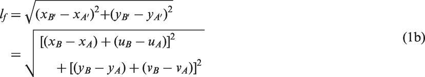

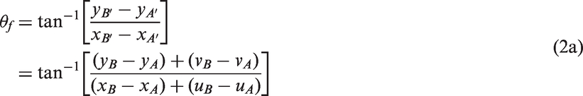
All the variables shown in equations (1) and (2) can be obtained from the results of meso-scale DIC analyses. Obtaining the local fiber stretch magnitude and its angle change facilitates a quantitative analysis of fiber trellising occurred in different off-axis specimens.
Results and discussion
Global stress–strain curves
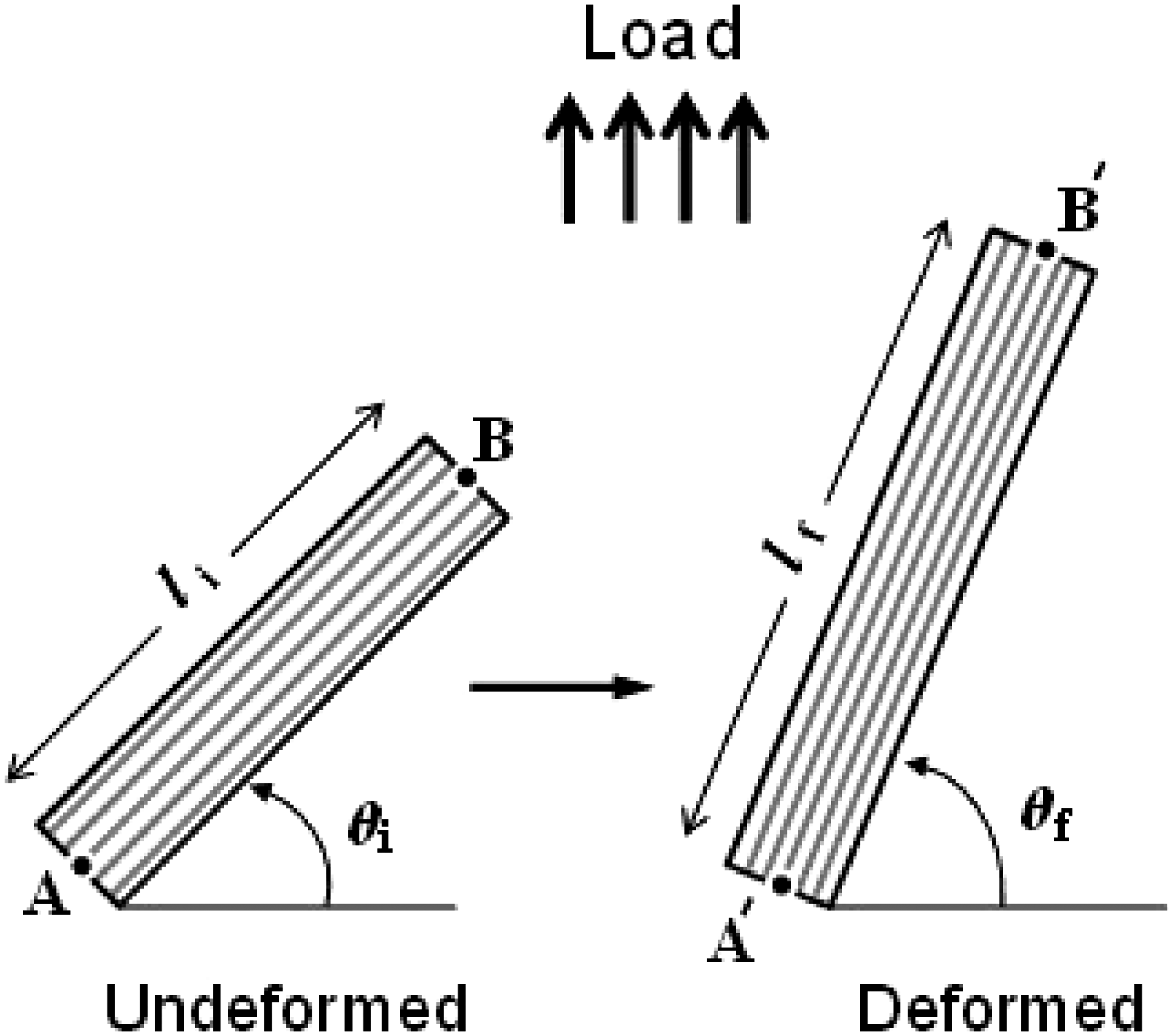
Global stress–strain curves of the off-axis specimens were obtained using two methods. First, following the conventional procedure, load and displacement in the gauge area were measured from the machine load-cell and cross-head motion, respectively, and the global flow curves were plotted. In the second approach, the load measured by the machine load-cell was used to determine the global stress value. However, the strain developed in the specimen was obtained by spatial averaging of the full-field vertical strain maps captured by DIC.2,3 Figure 4 shows the global true stress–strain curves obtained using the two approaches. Close agreement between the two sets of curves indicates that the field of view (10 × 10 mm2) used in the DIC analysis has been large enough to be statistically representative of the global response of the material.8,20
Global stress–strain curves obtained for the off-axis specimens.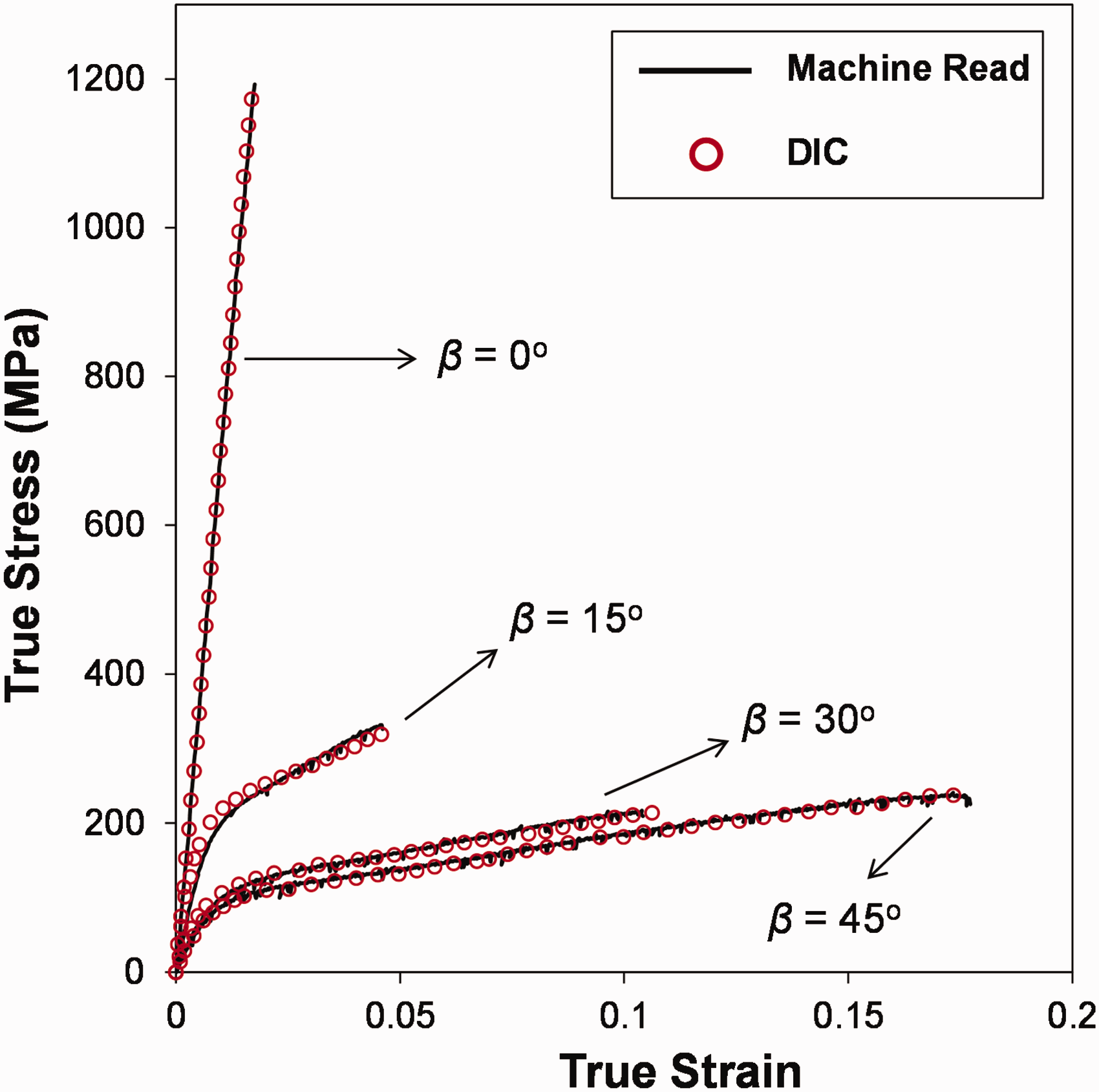
Global mechanical properties of the off-axis specimens.
The off-axis specimens exhibit significantly different mechanical response in terms of elastic modulus, Poisson’s ratio and strain-to-failure. The failure strain (
Meso-scale deformation response
Typical contours showing the evolution of full-field vertical strain on a 5 × 5 mm2 area at the center of 45° off-axis specimen are plotted in Figure 5. The contour maps show highly non-homogeneous strain fields, with noticeably large vertical strain component localized in multiple parallel inclined strips. Such heterogeneous full-field strain response agrees with the previous observations by Ivanov et al.
6
Note that the maximum local strain values shown here are considerably higher than the corresponding global strain in each image. This local non-homogeneous deformation response has also been observed in the case of other off-axis specimens, however, with different degrees of non-homogeneity.
Evolution of vertical strain component at different global strain magnitudes for 45° off-axis specimen. The global strain magnitude corresponding to each plot is indicated on the top. Far-field load is applied vertically.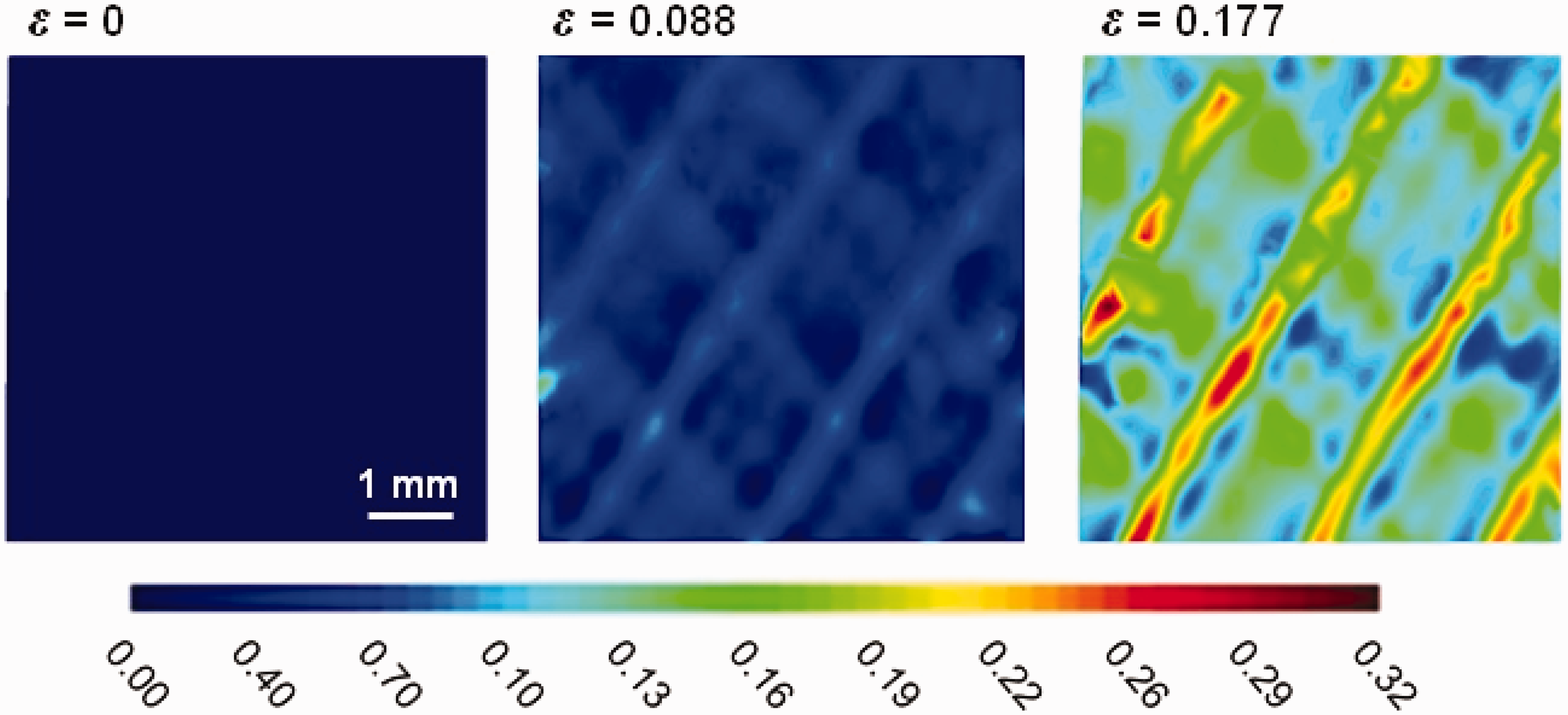
Figure 6 demonstrates the local non-homogeneity of the vertical strain at the instant of failure, for different off-axis specimens. Considering the locations of maximum and minimum local vertical strains, it is observed that for β = 0° the largest magnitude of local strain is developed within the areas containing mostly fiber bundles oriented parallel to the direction of the tensile load (see Figure 6(a)). This indicates that the longitudinal tows undergo the tensile deformation in β = 0°, and accordingly, it can be expected that the tensile load is mostly carried by these tows. Similar strain patterns were found experimentally and also by using FE modeling in literature.9,21 On the other hand, for off-axis specimens, i.e. β = 15°, 30° and 45°, the largest local strain is developed in epoxy-rich areas confined between longitudinal and transverse tows, as seen in Figure 6(b) and (c). Note that the degree of strain localization significantly increases in β = 45° specimen compared with β = 15°. In addition, the fiber-rich areas for these specimens show substantially lower strain magnitudes.
Full-field distribution of normalized vertical strain component (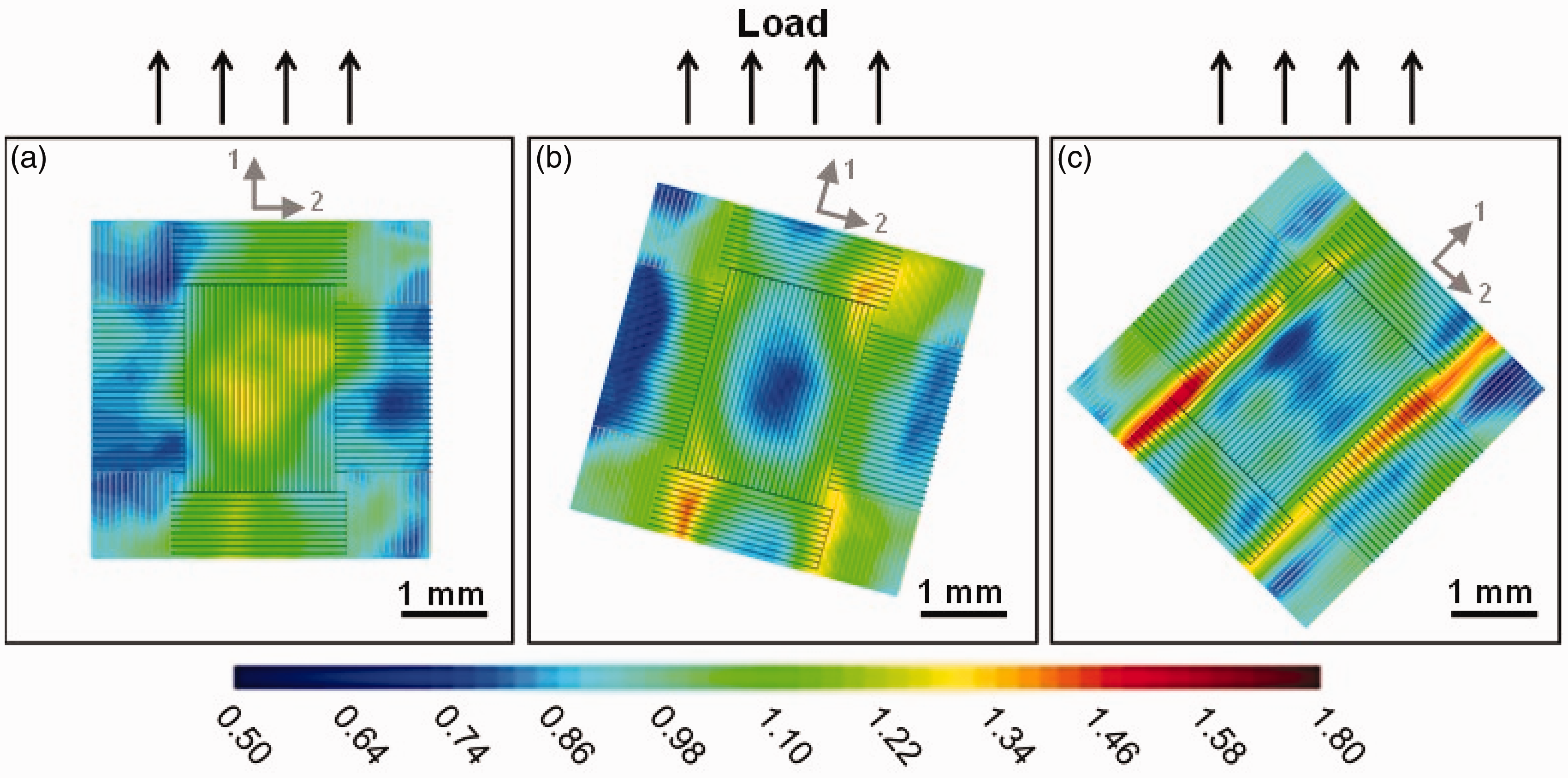
The comparison between two extreme cases, i.e. β = 0° and β = 45° has also been made by plotting the variation of normalized local vertical strain across three unit cells, as shown in Figure 7. Note that the curves in Figure 7 represent the variation of normalized vertical strain ( (a) Variation of normalized vertical strain component (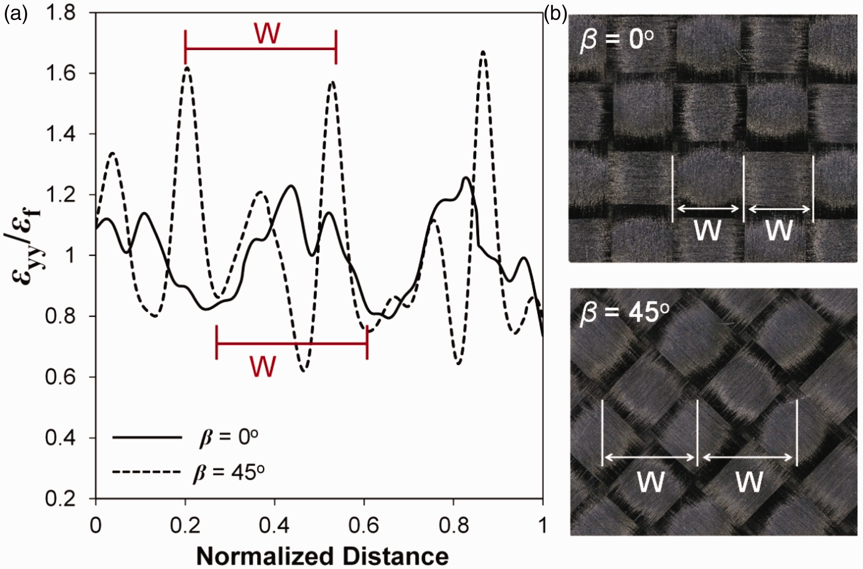
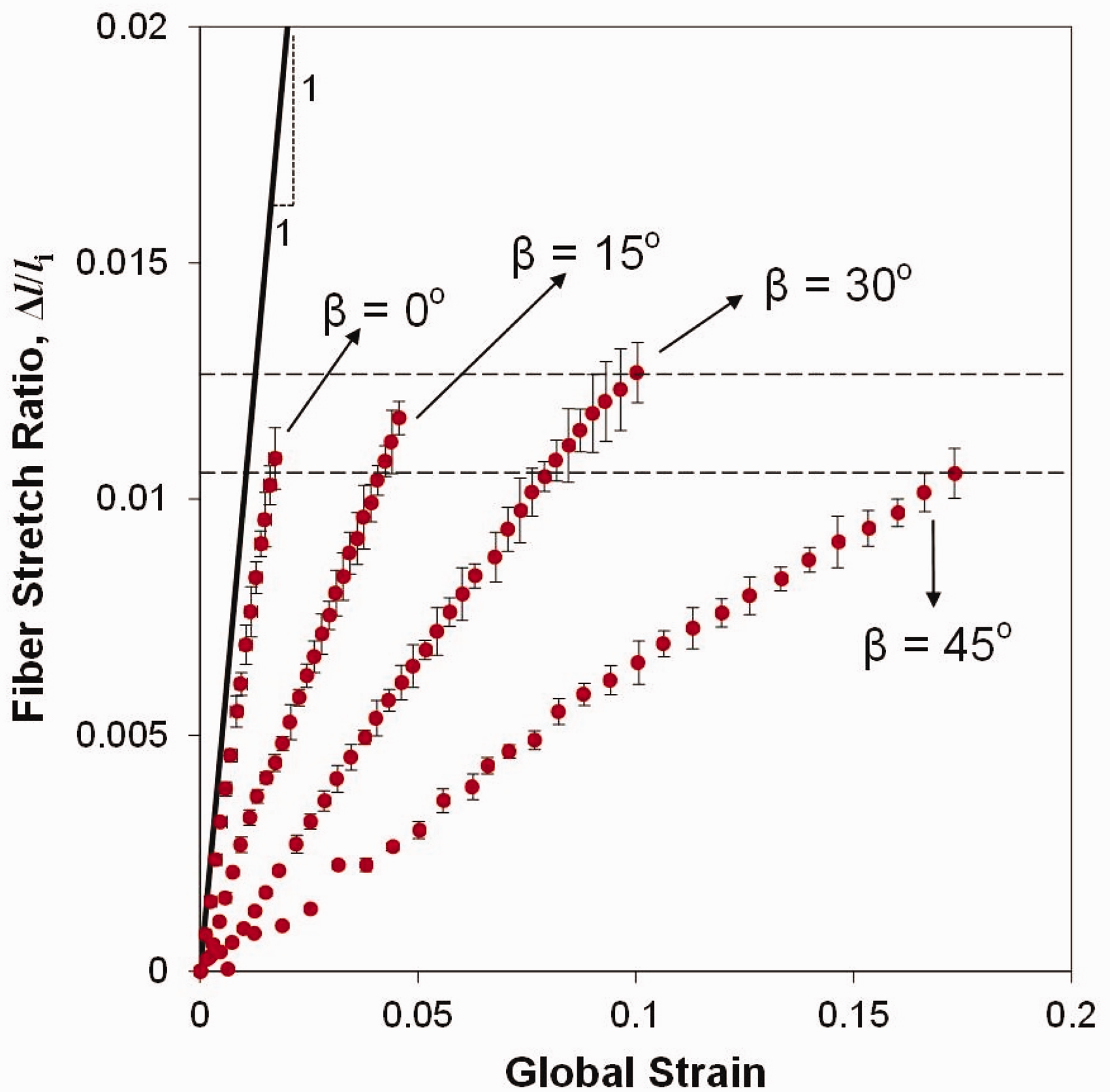
The magnitude of fiber stretch was measured for each specimen, according to equation (1). Figure 8 shows the variation of fiber stretch ratio, It is clearly observed that the value of the fiber stretch ratio in β = 0° at any given point during deformation is close to the global strain value applied on the specimen. This observation is in agreement with the discussion provided earlier on the more significant role of longitudinal fiber tows in load-bearing mechanism of this specimen. The slight deviation between the fiber stretch ratio and the global strain value in β = 0° specimen might be due to the fact that the global strain magnitude is measured over a significantly larger area that contains both longitudinal and transverse fiber bundles, as well as matrix-rich zones, while the stretch ratio is calculated locally without including the transverse bundles and matrix-rich areas. Due to this fact, the deviation between the fiber stretch ratio and the global strain magnitude significantly increases with increasing the angle between the fiber bundles and the loading direction. Although the global failure strain magnitudes of the specimens in the present work were found to be remarkably different, the magnitudes of their corresponding fiber stretch ratios upon failure were relatively close, being in the range of 1.07% to 1.28%. This agrees well with the fact that when failure occurs, the fiber stretch cannot be larger than the failure strain of the fiber, regardless of its tensile-loading angle. On the other hand, the larger values of global failure strains measured for specimens with 0° < β ≤ 45°might be attributed to fiber trellising.
19
Variation of fiber stretch ratio (Δli) with respect to the global vertical strain for different off-axis specimens examined in this work.
The fiber rotation angles calculated based on equation (2) are depicted in Figure 9 for different specimens. It is clearly observed that the angle of fiber rotation calculated for the off-axis specimens is substantially larger compared with the on-axis specimen. It is also evident that the β = 45° specimen exhibits the largest value of rotation, Variation of fiber rotation angle ( Full-field distribution of shear strain component (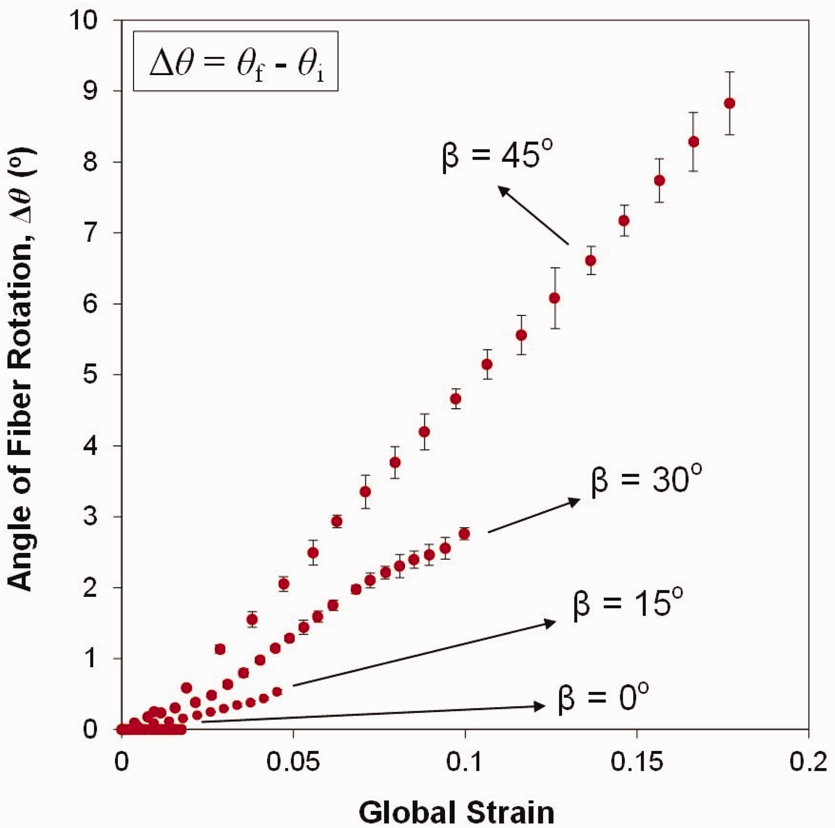

Further post-mortem investigations revealed that the occurrence of large in-plane rotations in off-axis specimens can increase surface asperity of the deformed material. Figure 11 depicts the high-magnification images taken from the surface of the specimens after failure. The degree of the so-called surface asperity is significantly higher for β = 45° and is decreased progressively as β converges to 0°. Also, the 3D profile measurements conducted on the specimen surface indicate that the peak value of the surface asperity for β = 45° is located over the intersection of longitudinal and transverse fiber tows.
High-magnification images showing the surface profile of for (a) β = 0° and (b) β = 45° off-axis specimens after failure. The magnitudes of the surface elevation along the transverse direction (dashed line marked on (a) and (b)) are plotted in (c).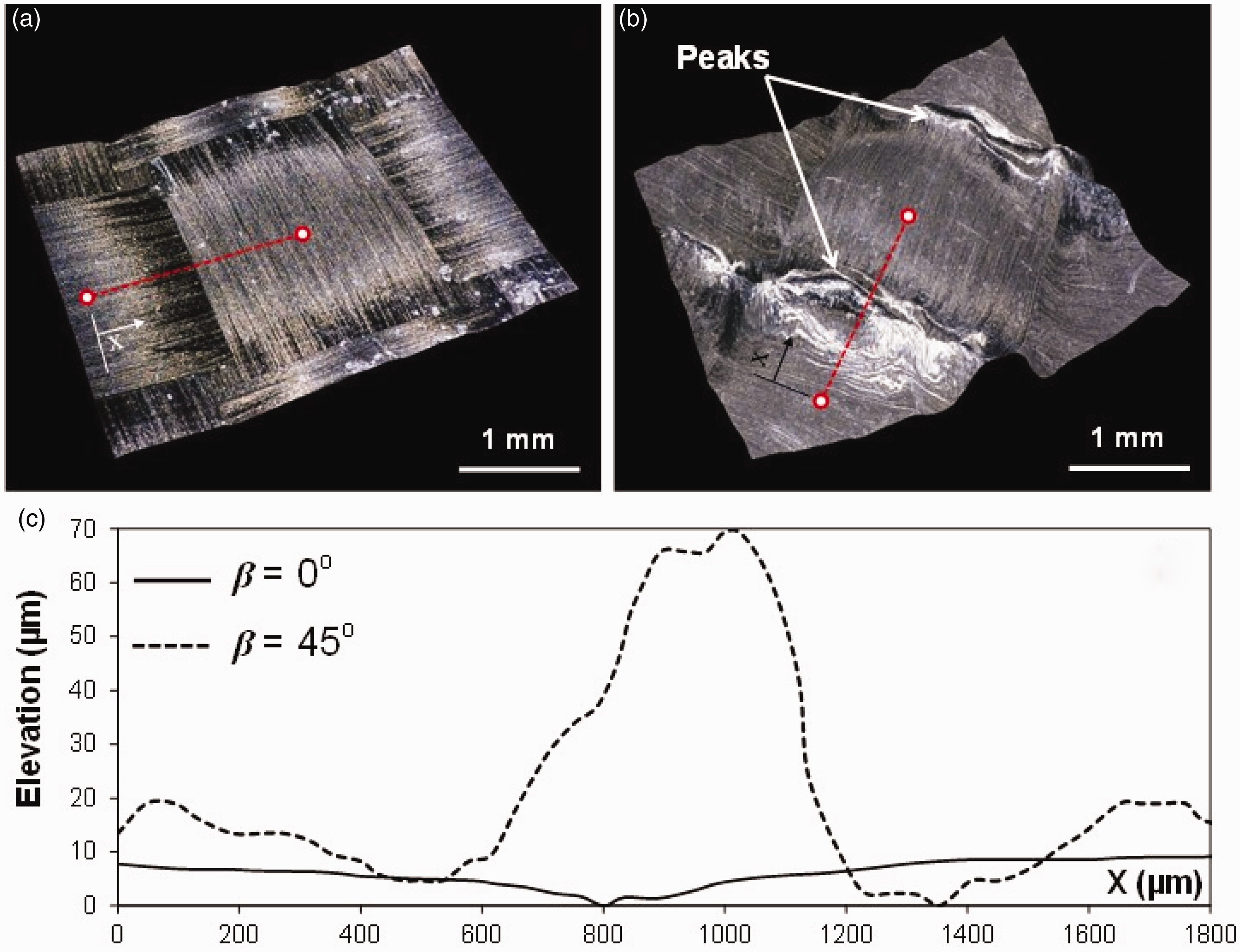
The observation of the developed local surface asperities in β = 45° can again be explained through the fiber trellising mechanism. As discussed earlier, the large rotation of the fibers can exert substantially large values of shear deformation on the epoxy regions confined within the orthogonal fiber tows. This large deformation magnitude may eventually cause the relatively softer epoxy to be extruded out of the plane of the lamina. This mechanism results in the formation of surface asperities over the epoxy-rich regions on the surface ply, as illustrated earlier in Figure 11. However, the occurrence of such local out-of-plane deformation of the epoxy within the inner plies of the composite sheet may give rise to the partial delamination of the plies, yielding in the nucleation of internal damage. The explained mechanism can be considered as a possible internal damage mechanism for woven composite subjected to off-axis tensile-loading conditions and can be a point of interest for future investigations on the subject.
Conclusions
Off-axis tensile deformation response of an orthogonally woven carbon fiber-reinforced composite was studied at mesoscopic scales. Stereovision DIC was used to capture full-field displacement and strain distributions over a millimeter-sized area at the center of the specimens. The significantly different global mechanical responses of the off-axis specimens in this work were explained through the load-bearing mechanisms as a function of fiber orientation, while the experimental data were used to validate the proposed mechanisms. Non-linear response observed in specimens with 0° < β ≤ 45° relative to the loading direction were explained as a result of the concurrent deformation of fibers and matrix. The experimental results also indicated that such non-linear response is mainly due to the occurrence of the in-plane rotation of longitudinal and transverse fiber tows, imposing large shear strains onto the softer epoxy-rich regions within the material.
Footnotes
Acknowledgements
The College of Engineering and Computing and the Department of Mechanical Engineering at the University of South Carolina are gratefully acknowledged.
Declaration of Conflicting Interests
The author(s) declared no potential conflicts of interest with respect to the research, authorship, and/or publication of this article.
Funding
The author(s) received no financial support for the research, authorship, and/or publication of this article.