
Abstract
Carbon fiber-reinforced plastics (CFRP) have been widely applied in aerospace industry as structural components due to their excellent mechanical and physical properties. Meanwhile, the drilling process is indispensable for machining the assembly holes of CFRP. However, in the conventional drilling process of CFRP, it is prone to produce the defects including delamination, spalling, fuzzing, and tool wear. In recent years, the rotary ultrasonic-assisted drilling (RUAD) with diamond core drill, as a novel machining method, has been employed to reduce the defects. But this is few reported investigations on chip adhesion of tool surface and machined rod jamming into core drill tool during RUAD of CFRP. Therefore, this paper detailedly reported a study on removal analyses of chip and rod in RUAD of CFRP using core drill under no cooling condition for the first time. To begin with, the principle analysis on RUAD of CFRP was presented to illustrate the removal process of chip and rod. And then, the experiment analysis on RUAD of CFRP was carried out to observe the removal effects of chip and rod. The experimental results indicated that compared with the common drilling of core drill, when the vibration amplitude reached 5.0 and 7.5 µm in RUAD, the cutting ability of core drill tool was greatly enhanced, excellent removal effects of chip and rod were obtained, which obviously reduced the chip adhesion, rod jamming, rod fragmentation, thrust force, cutting temperature, and surface roughness, improved the dimensional accuracy of machined hole and rod diameter, prolonged the tool life, as well as acquired superior surface integrity of machined hole and flat fibers fracture surfaces. Furthermore, the experimental results also validated the accuracy of the principle analysis.
Keywords
Introduction
Carbon fiber-reinforced plastics (CFRP) are seen as an advanced material, which have been widely used in aerospace industry as structural components because of their excellent properties such as high specific strength, high specific modulus, high hardness, corrosion resistance, wear resistance, low density, and low thermal expansion coefficient.1,2 For example, the employ of CFRP in Boeing 787 and Airbus A350 XWB is more than 50% of its structural weight for their main airframes.3,4
In the application process of CFRP, a large number of assembly holes need to be machined. Drilling technology is a conventional method that used in machining these holes. However, it is known to all that the drilling process of CFRP hole will be difficult because of the anisotropic structure, abrasive nature, low thermal conductivity, high specific strength, and high hardness. 5 For instance, primary defects generated in the drilling process include the delamination, exit spalling, fuzzing, fiber pullout, fiber breakage, and poor surface roughness of drilled CFRP hole as well as the rapid tool wear.5,6
In order to improve the drilling process of CFRP hole and mitigate machining defects, different methods have been reported as follows. Firstly, with regard to the clamping ways of CFRP workpiece during drilling, the most prevalent way of reducing exit delamination, spalling, and fuzzing damages is to support the bottom plies of CFRP workpiece.7–11 Secondly, as far as the cutting tool is concerned, various tools consisting of twist drill, saw drill, step drill, candle stick drill, multifacet drill, core-special drill, dagger drill, and diamond core drill are fabricated and compared for the drilling process of CFRP.10–22 The results indicated that compared to other tools, the diamond core drill is advantageous for reducing the delamination, spalling, fuzzing, and tool wear during the drilling process of CFRP, but the chip adhesion and machined rod jamming occurred to core drill tool easily. Thirdly, in terms of the cutting mode, the drilling tool is assisted by rotary ultrasonic vibration can achieve much better machined results than conventional drilling, such as fewer machining defects, better surface integrity, higher dimensional precision, lower cutting force, and temperature, as well as higher tool life.22–32
In recent years, the rotary ultrasonic-assisted drilling (RUAD) with diamond core drill, as a novel machining method, has been successfully employed to machine the CFRP hole; it is a non-traditional and hybrid drilling process, which combined material removal mechanisms of diamond grinding and ultrasonic drilling characteristics.22,26,27 Figure 1 illustrates the schematic of RUAD process with supported plate (see Figure 1(a)) and diamond core drill (see Figure 1(b)).
Illustration of (a) RUAD with supported plate and (b) diamond core drill. CFRP: carbon fiber-reinforced plastics.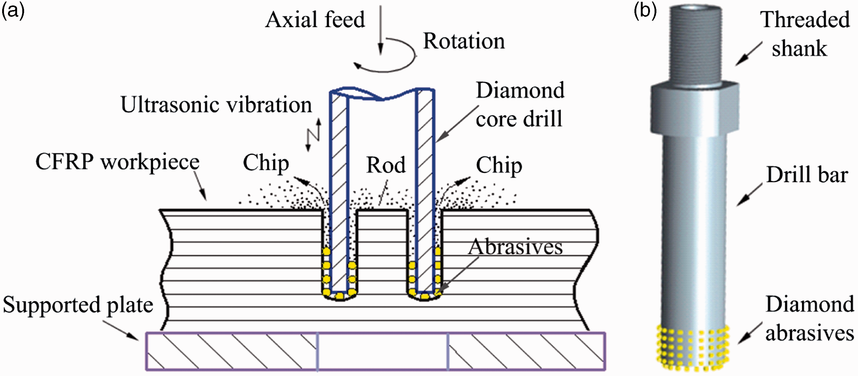
So far, although there were some investigations on rotary ultrasonic machining of CFRP using core drill, few reported studies were implemented to analyze the removal process and effects of chip and rod in the ultrasonic machining of CFRP using core drill under no cooling condition. Besides, the cutting process and failure modes of core drill tool in rotary ultrasonic machining of CFRP without coolant would be different from that with a cooling system. Therefore, this paper first presented a principle and experiment analysis on the removal process and effects of chip and rod in RUAD of CFRP using core drill under no cooling condition. It is divided into five sections. After this “Introduction” section, the principle analysis on RUAD of CFRP is described in “Principle analysis on RUAD of CFRP” section. Next, the material properties of workpiece, novel experimental set-up, experimental conditions, and measurement procedures are illustrated in “Experiments” section, respectively. And then, the experimental results and discussion are presented in “Experimental results and discussion” section. Finally, the conclusions are drawn in “Conclusions” section.
Principle analysis on RUAD of CFRP
Kinematic analysis on single abrasive in RUAD
Compared with common drilling (CD), the RUAD has unique characteristics such as motion trajectory with ultrasonic vibration, separated intermittent cutting locus, and cutting characteristics of velocity change.
The motion trajectory of single abrasive on core drill tool for RUAD is illustrated in Figure 2(a). The diamond core drill rotates round the tool axis (i.e. Z axis), vibrates and feeds along the Z axis simultaneously. Therefore, the motion trajectory of single abrasive on core drill tool for RUAD is a spatial three-dimensional (3D) spiral curve with sinusoidal variation. The motion trajectory equation of single abrasive in RUAD can be written as
Motion trajectory (a), cutting locus, (b) and cutting profile (c) of single abrasive for RUAD. (a) Motion trajectory of single abrasive on core drill tool for RUAD, (b) separated intermittent cutting of single abrasive on the tool end face for RUAD, and (c) schematic of machined hole and rod surface modification in RUAD. CD: conventional drilling; RUAD: rotary ultrasonic-assisted drilling; CFRP: carbon fiber-reinforced plastics.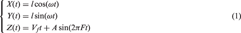
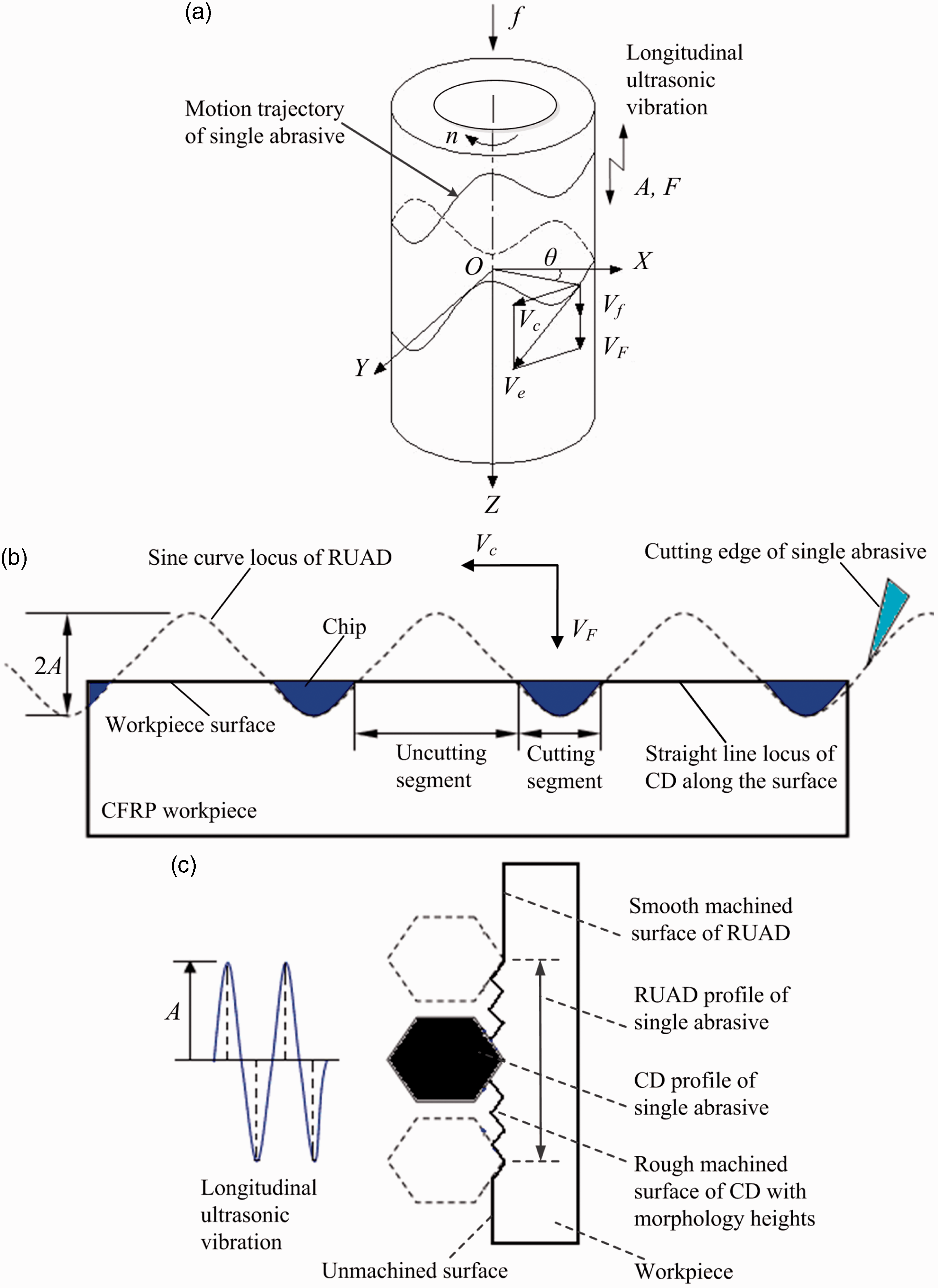
In addition, in Figure 2(a), n is the rotary speed (r/min), f is the feedrate (mm/r), VF is the velocity of ultrasonic vibration (mm/s), Vc is the tangential velocity (mm/s), and Ve is the synthetic cutting velocity (mm/s).
Similarly, the motion trajectory equation of single abrasive in CD can be expressed as
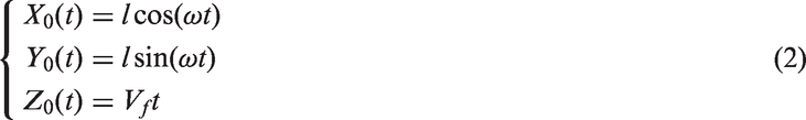
The separated intermittent cutting locus of single abrasive on the tool end face for RUAD is depicted in Figure 2(b), while the cutting locus of single abrasive on the tool end face for CD is unseparated contact cutting along workpiece surface. Due to the alternative separation and contact between the tool end face and workpiece surface (i.e. hole bottom) during RUAD, which will greatly improve the removal of chip, mitigate the rod jamming, and reduce the friction effect.24,33,34 Meanwhile, the high-frequency longitudinal vibration action of RUAD can help to shake off the chip of tool surface significantly. In addition, owing to the action of additional velocity VF during RUAD, the tool cutting ability and cutting efficiency will be enhanced significantly and a impulse force (i.e. ultrasonic impact action) will generate, which will make the tool more easy to cut off the fibers and epoxy matrix and obtain the larger cutting depth (i.e. acquire a high material removal rate) and lower cutting force.29,35–37 From the above, these actions will result in the obvious decreases in thrust force, cutting temperature, chip adhesion of tool surface, and rod jamming during RUAD compared to that during CD. As a result, the tool life of core drill can be greatly prolonged, the machining quality of drilled hole can be significantly improved, and the ultrasonic self-cleaning function can be attained during RUAD.
The modification characteristics of machined hole and rod surface in RUAD are described in Figure 2(c). In the picture, the single abrasive on the inside or outside surface of core drill tool is excited with a longitudinal ultrasonic vibration, and the constant contact between the abrasive of tool inside or outside surface and machined surface (i.e. hole surface or rod surface) is kept. Consequently, the engagement geometry of each abrasive in RUAD is modified, i.e. the cutting profile of each abrasive in RUAD is enlarged, the cutting length of each abrasive on the machined surfaces of CFRP hole and rod is increased, which will help to reduce the surface roughness of CFRP hole and rod (i.e. acquire the smooth-machined surface) and achieve excellent surface integrity, this can be regarded as longitudinal ultrasonic smoothing effect. In other words, the longitudinal ultrasonic vibration gives rise to the vibratory rubbing motion of tool inside and outside surface abrasives over the machined surface, which can smooth the machined surface morphology heights by the overlapping of adjacent cutting trajectories.
The length of each abrasive trajectory for RUAD and CD in the time interval [t1,t2] can be expressed as
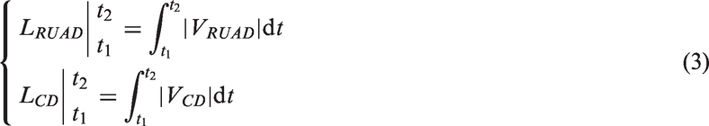
According to Figure 2(a),
Cutting characteristics of velocity change for RUAD
As shown in Figure 2(a), the axial motion trajectory equation of any single abrasive on the tool surface in RUAD can be expressed as

The velocity VF of ultrasonic vibration can be derived by

As a result, the velocities of any single abrasive in RUAD can be written as
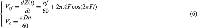
And the synthetic cutting velocity Ve of any single abrasive in RUAD can be expressed as
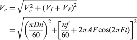
Therefore, on the basis of the equations (6) and (7), during RUAD of CFRP with longitudinal ultrasonic vibration, owing to the periodic change characteristics of velocities
Analysis on cutting process of RUAD of CFRP
In the first place, the 3D cutting process models for RUAD and CD of CFRP are established, as shown in Figure 3(a) and (b), respectively. Besides, the diamond abrasives of tool end face are regarded as main cutting edge, and the diamond abrasives of tool inside and outside surface are considered as minor cutting edge.
Three-dimensional cutting process models for RUAD and CD of CFRP. (a) RUAD model of CFRP and (b) CD model of CFRP. CFRP: carbon fiber-reinforced plastics.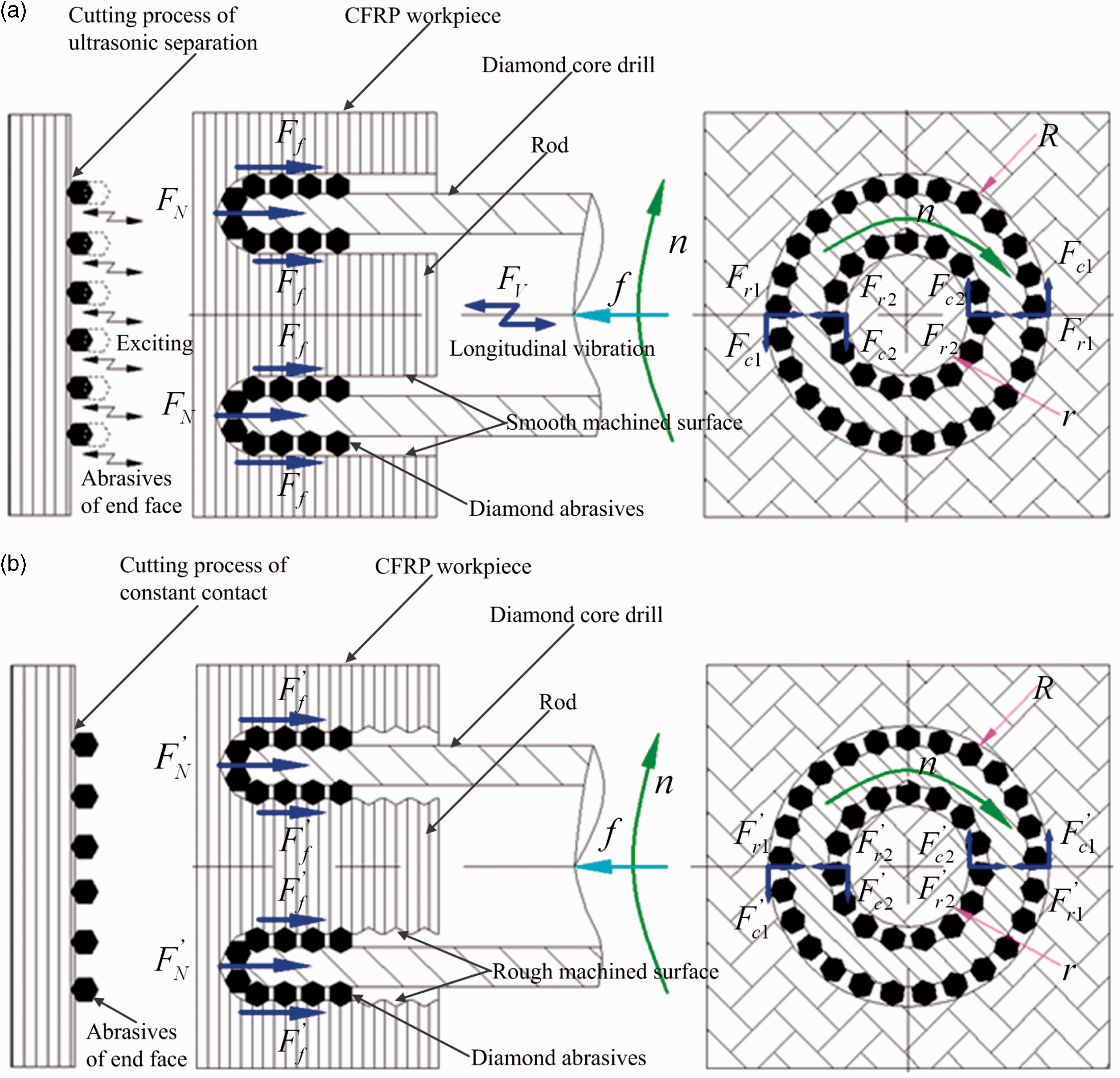
As seen in Figure 3(a), the mean thrust force

With the help of the friction mechanics theory, the friction force Ff can be written as


By substituting equations (9) and (10) into equation (8), the following relationship can be obtained, i.e.

Similarly, as shown in Figure 3(b), the mean thrust force

According to the equations (11) and (12), Figures 2 and 3, compared with CD of CFRP, the following results can be concluded for RUAD. Firstly, owing to the action of impulse force Fv, it will make the tool generate periodic separation and contact between the tool end face (i.e. tool main cutting edge) and workpiece surface (i.e. hole bottom) during RUAD, which will greatly improve the removal of chip, mitigate the rod jamming, and reduce the friction effect. Meanwhile, the stiffness and cutting ability of core drill tool will be enhanced so that the carbon fibers and epoxy matrix can be cut off easily (i.e. the flat fibers fracture surfaces, lower cutting force, high cutting efficiency, and high material removal rate can be achieved). Thus, the cutting temperature and mean thrust force of RUAD can be decreased significantly compared to that of CD, which will help to reduce the chip adhesion of tool surface and prolong the tool life. Secondly, due to the better chip removal effect, higher tool cutting ability, lower cutting force and temperature and few chip adhesion in RUAD, so the radial extrusion forces of machined CFRP hole and rod in RUAD are lower than that in CD, which cause the radial force
Therefore, with the help of above excellent tool cutting abilities and effects in RUAD, the machining defects (e.g. delamination, exit spalling, fuzzing, fiber pullout, matrix damage, poor surface roughness of drilled hole, chip adhesion of tool surface and rod jamming into tool, and so on) can be effectively decreased in RUAD of CFRP.
Experiments
Material properties of workpiece
Material properties of workpiece.

CFRP: carbon fiber-reinforced plastics.
Experimental set-up and conditions
The diamond core drill was comprised of diamond abrasives and drill bar as well as manufactured by vacuum brazing technique to weld diamond abrasives on the drill bar, which was provided by Fujian Wanlong Diamond Tools Co., Ltd. The sample of diamond core drill and associated abrasive distribution were shown in Figure 4. The outer and inner diameter of the diamond core drill was 7.5 and 4.9 mm, respectively, and the total length was 100 mm. The abrasive size was about 0.25 mm and the concentration of diamond abrasives on drill bar surface was about four abrasives in each square millimeter (i.e. 4/mm2). During RUAD, diamond core drill was connected to the rotary ultrasonic spindle in order to supply ultrasonic axial vibration towards the CFRP workpiece and rotary motion, while the axial feed rate relied on a lathe machine table (i.e. CA6140 lathe machine).
Sample of diamond core drill and associated abrasive distribution. (a) abrasive distribution of lateral face and (b) abrasive distribution of end face.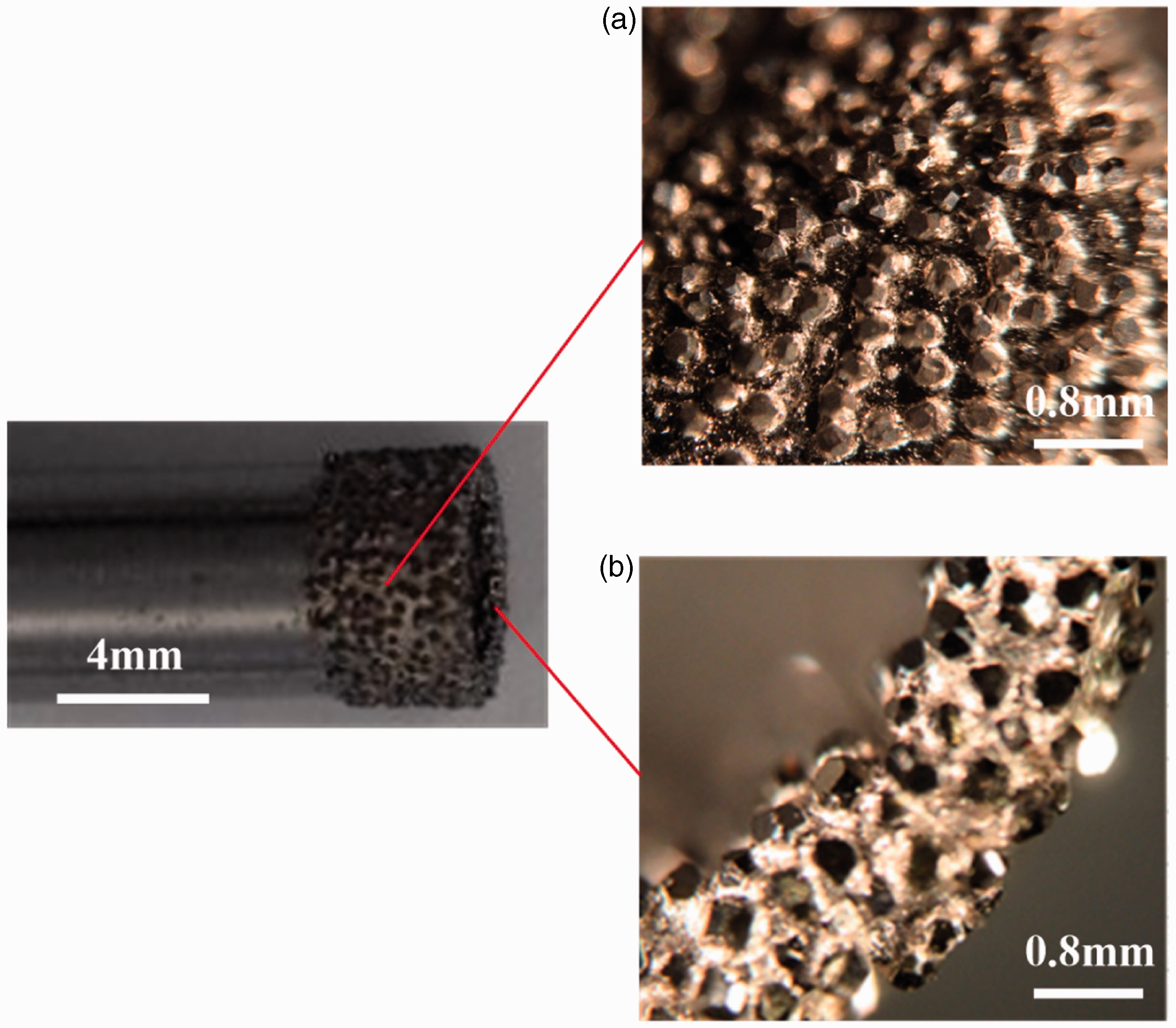
In order to realize the high rotary speed of RUAD, a conventional air drill with 6000 r/min speed was used to connect the designed rotary ultrasonic vibration drilling spindle by threaded connection so as to provide the rotary power. Meanwhile, the both ends of vibration drilling spindle were supported by bearings and the spindle was enclosed in a cylinder, it could also be applied in other conventional machine tool. The resonance frequency of ultrasonic vibration air drill was measured with the help of impedance analyzers, as well as the optimum vibration frequency was about 21.5 KHz. Figure 5 includes the ultrasonic vibration air drill that was developed by Beihang University for the first time, it was more convenient to adapt the assembly process of CFRP in aircraft industry due to the restrictions of machining environment and space.
Experimental set-up. (a) RUAD of CFRP with supported plate and the measurement of thrust force, (b) RUAD of CFRP without supported plate and the measurement of cutting temperature, and (c) schematic of rotary ultrasonic vibration drilling spindle. CFRP: carbon fiber-reinforced plastics.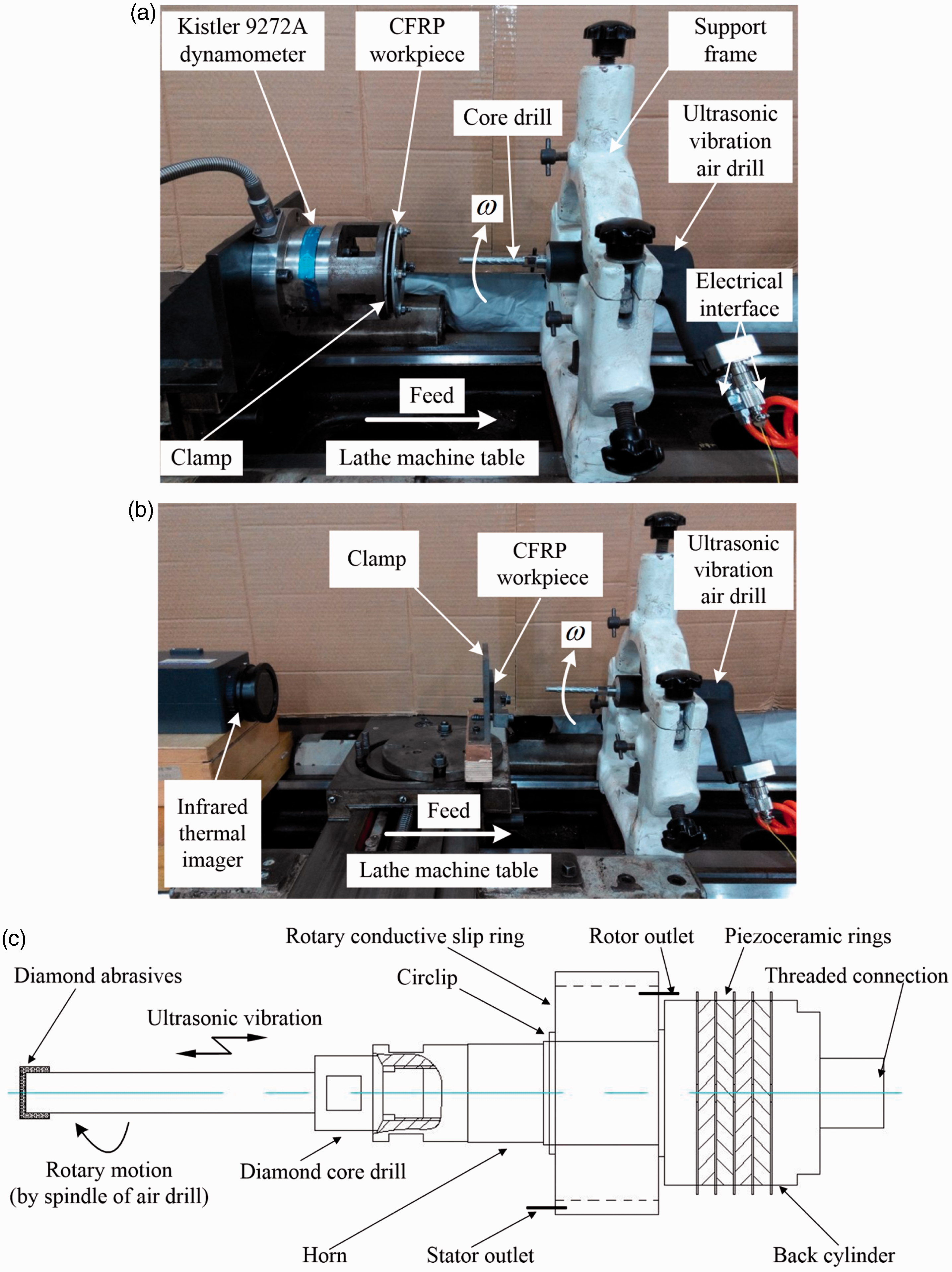
The experimental platforms were set up, as illustrated in Figure 5. Figure 5(a) shows the RUAD of CFRP with supported plate and the measurement of thrust force. Figure 5(b) shows the RUAD of CFRP without supported plate and the measurement of cutting temperature. In the experiments, the measurements of drilling force and cutting temperature were divided into two experiments as well as carried out, respectively. In the two experiments, four new diamond core drills were used for four CFRP specimens in each experiment, meanwhile, the numbers of drilled hole for each CFRP specimen were eight. The experimental platforms consisted of a CA6140 lathe machine, an ultrasonic vibration air drill with 6000 r/min speed, an ultrasonic power supply, a force measuring system, a temperature measuring system, an air storage tank, diamond core drill, support bases, clamps, and bolts. In addition, ultrasonic vibration air drill was fixed on the middle skateboard of the lathe by means of the support base.
Figure 5(c) shows the schematic of designed rotary ultrasonic vibration drilling spindle, which was considered as the main part of ultrasonic vibration air drill. The rotary ultrasonic vibration drilling spindle was composed of diamond core drill and sandwiched piezoelectric ceramic rotary ultrasonic transducer with ladder type horn. The sandwiched piezoelectric ceramic rotary ultrasonic transducer consisted of ladder type horn, rotary conductive slip ring, circlip, piezoceramic rings, and back cylinder. This sandwiched transducer had many advantages such as the high-output power, high-electroacoustic transforming efficiency, excellent heat resistance, easy to be designed and assembled, and so on.38–40
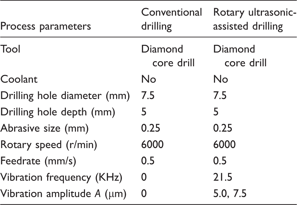
Experimental conditions.
Measurement procedure and conditions
A laser micrometer system was used to measure the ultrasonic vibration amplitude of the core drill end face (i.e. tool tip), which was comprised of a laser micrometer controller (LK-G5000 series) and LK-Navigator 2 software. LK-Navigator 2 was software for configuring parameters and monitoring the LK-G5000 series controller. It was used by connecting a PC and the controller to configure parameters and monitor operating status.
The vibration amplitude of each tool should be measured before each experiment, as well as the amplitude was adjusted by the supplied ultrasonic power.
A Kistler 9272A piezoelectric dynamometer was employed to measure the thrust force in the drilling process of CFRP. The force signals from the dynamometer were transmitted to Kistler 5070A charge amplifier and converted to digital signals by means of an A/D converter. And then, the obtained digital signals were displayed and recorded on an industrial personal computer in virtue of Kistler Dynoware software. Figure 5(a) illustrates the measurement setup of thrust force.
An infrared thermal imager was applied to measure the cutting temperature near drilled hole exit, because the cutting temperature in the drilling process of CFRP came mainly from the cutting zone between tool end face (i.e. tool main cutting edge) and workpiece surface (i.e. hole bottom). The obtained temperatures were displayed and recorded on an industrial personal computer by means of IRBIS®3 Plus software. Figure 5(b) illustrates the measurement setup of cutting temperature.
A surface profilometer (Form Talysurf 50, Taylor Hobson, England) was adopted to measure the surface roughness of drilled hole, and four measurements were carried out with a adjacent angle of 90° for each hole. Meanwhile, the surface roughness in this paper was the mean value of four measurements for each hole. The profilometer consisted of sensor of adjustable position with contact probe, driving box, and electrical box. The obtained values of surface roughness were displayed and recorded on a personal computer. The sampling length (i.e. cut-off length) was set at 0.8 mm, and the evaluation length was five times than sampling length (i.e. the evaluation length was 4 mm).
Experimental results and discussion
Effects of RUAD on the removal effects of chip and rod
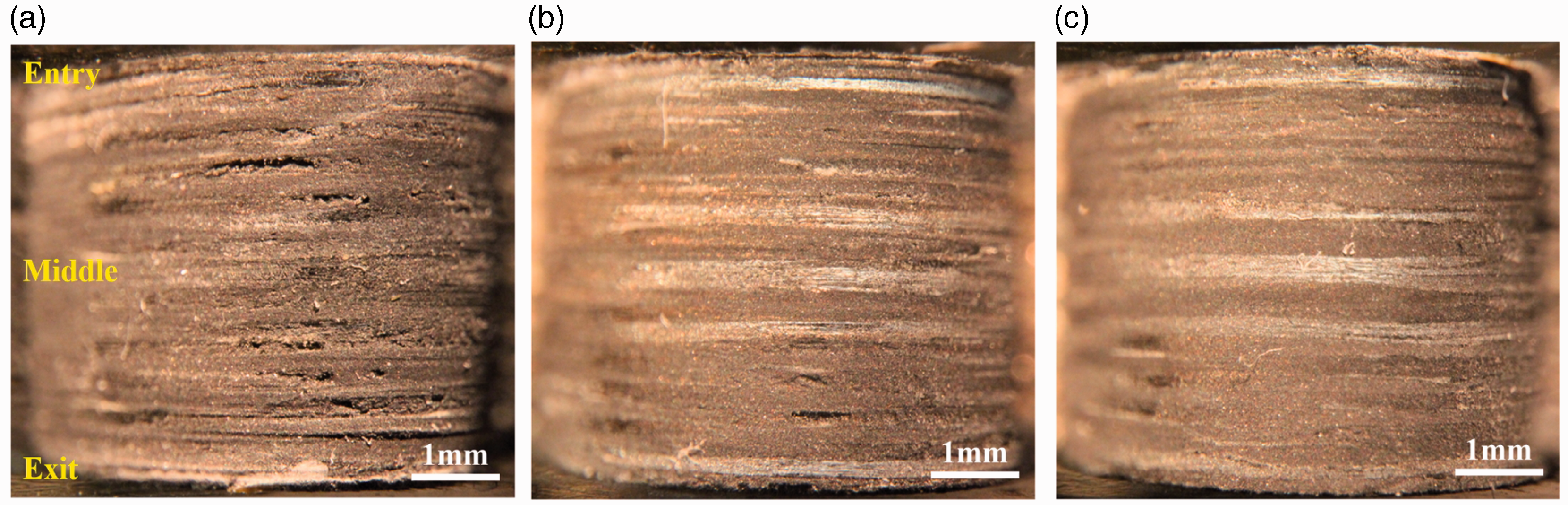
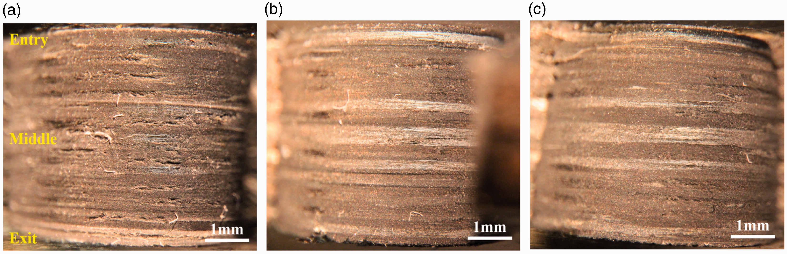
The comparisons for the removal effects of chip and rod in RUAD and CD after the first, fifth, and eighth drilled holes were presented in Figures 6 to 8, respectively.
Comparisons for the removal effects of chip and rod after the first drilled holes. (a) CD, (b) RUAD 5.0 µm, and (c) RUAD 7.5 µm. Comparisons for the removal effects of chip and rod after the fifth drilled holes. (a) CD, (b) RUAD 5.0 µm, and (c) RUAD 7.5 µm. Comparisons for the removal effects of chip and rod after the eighth drilled holes. (a) CD, (b) RUAD 5.0 µm, and (c) RUAD 7.5 µm.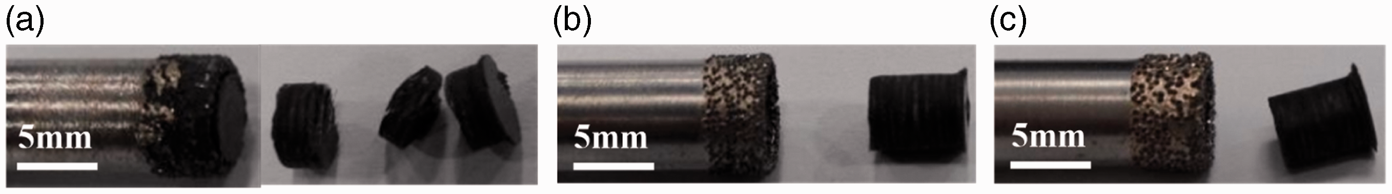
It can be seen from Figure 6(a) that a few chips adhered to the tool surface and the tool inner rod was difficult to remove after the CD. Meanwhile, in Figure 6(a), fragmentation occurred to the machined rod when the rod was took out by dismantling the core drill tool. However, there was no chip adhered to the tool surface and the tool inner rod was removed easily after the RUAD with the vibration amplitudes of 5.0 and 7.5 µm (see Figure 6(b) and (c)). Besides, in Figure 6(b) and (c), no fragmentation occurred to the machined rod (i.e. intact rod was obtained) and the rod was shaked off easily because of the ultrasonic vibration and ultrasonic self-cleaning function.
As shown in Figures 7(a) and 8(a), it can be observed that the tool surface was adhered by chip seriously and the rod was jammed into core drill after the CD, which made it become more difficult to remove the tool inner rod and surface chip. Meanwhile, in Figures 7(a) and 8(a), serious fragmentation occurred to the machined rod when the rod was took out by dismantling the core drill tool. Nevertheless, there was also no chip adhered to the tool surface and the inner rod was removed easily after the RUAD with the vibration amplitudes of 5.0 and 7.5 µm (see Figures 7(b) and (c) and 8(b) and (c)). Furthermore, in Figures 7(b) and (c) and 8(b) and (c), no fragmentation also occurred to the machined rod and the rod was shaked off easily because of the ultrasonic vibration and ultrasonic self-cleaning function. In summary, compared with the CD, owing to the ultrasonic self-cleaning function (i.e. excellent removal effects of chip and rod) and enhanced tool cutting ability during RUAD, which decreased the radial extrusion force of rod surface and chip adhesion of tool surface as well as smoothed the rod surface because of the longitudinal ultrasonic smoothing effect, thereby remarkably reduced the chip adhesion, rod jamming, and fragmentation.
In addition, Figures 6 to 8 still show that the surface of machined rod was more flat in RUAD with the vibration amplitudes of 5.0 and 7.5 µm than that in CD. Meanwhile, Figures 6 to 8 also proved that the removal effects of tool surface chip and inner rod could be improved greatly as well as the tool life could be prolonged significantly during RUAD with the appropriate vibration amplitude of 5.0 or 7.5 µm. It can still be confirmed that the RUAD had the functions of ultrasonic self-cleaning and machined surface smoothing.
Therefore, in contrast to CD of CFRP, based on the superior removal effects of chip and rod during RUAD, it could be inferred that the cutting ability and life of core drill tool were enhanced significantly; the thrust force, cutting temperature, surface roughness, chip adhesion, and rod jamming could be reduced; the excellent surface integrity of machined hole could be obtained and the machining defects could be mitigated. These figures from Figures 6 to 8 further indicated that the main failure mode of core drill tool during CD of CFRP without coolant was the adhesive failure (i.e. the chip adhesion of diamond abrasives at tool surface) due to the poor chip removal condition of CD, while the chief failure mode of core drill tool during RUAD of CFRP without coolant was the abrasive wear failure (i.e. the wear of diamond abrasives at tool surface) because of the excellent ultrasonic separated intermittent impulse cutting characteristics and ultrasonic self-cleaning function of RUAD, and then the adhesive failure of tool would appear in RUAD because of the poor cutting ability of dull diamond abrasives after using the tool for a long period of time. Furthermore, when the diamond abrasives of tool surface were completely covered and adhered by chip, the tool cutting ability would lose completely and the tool life should be terminated.
Effects of RUAD on the measured parameters
In the experiments, the feed rate (i.e. 0.5 mm/) and rotary speed (i.e. 6000 r/min) kept the constant. The measured parameters consisted of the thrust force, cutting temperature near the drilled hole exit, surface roughness, hole diameter, and rod diameter. Figures 9 to 13 show the effects of RUAD on the mean thrust force, maximum cutting temperature near the drilled hole exit, mean surface roughness of drilled holes, hole diameter, and rod diameter, respectively. In addition, the drilling process of each hole could be divided into three stages, i.e. the drilling of hole entry, stable drilling of hole middle, and drilling of hole exit.
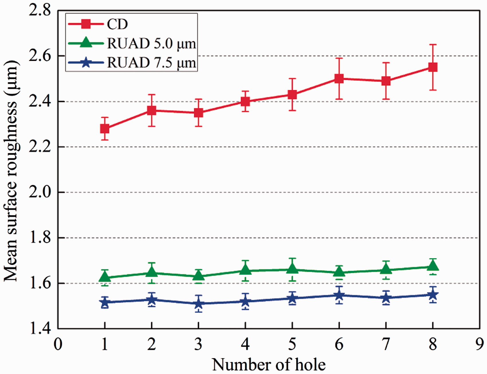
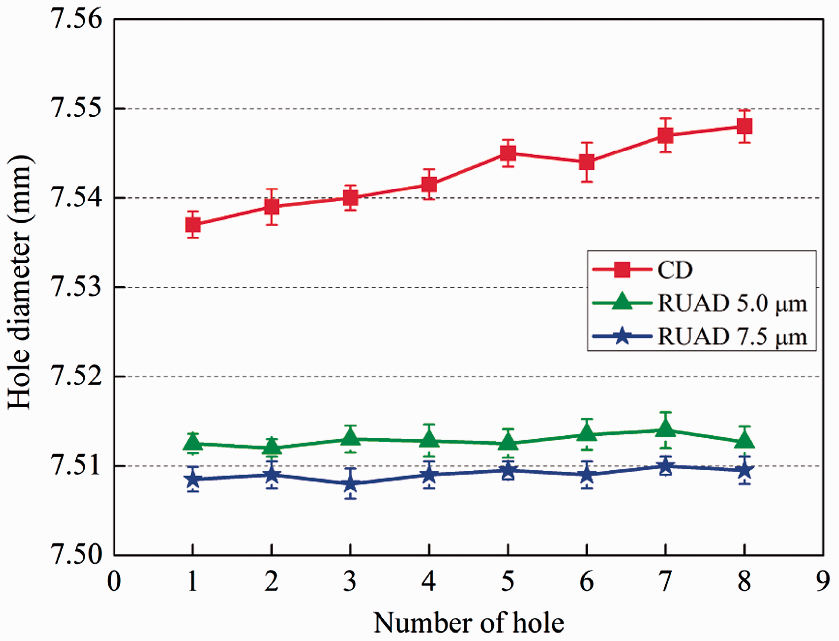
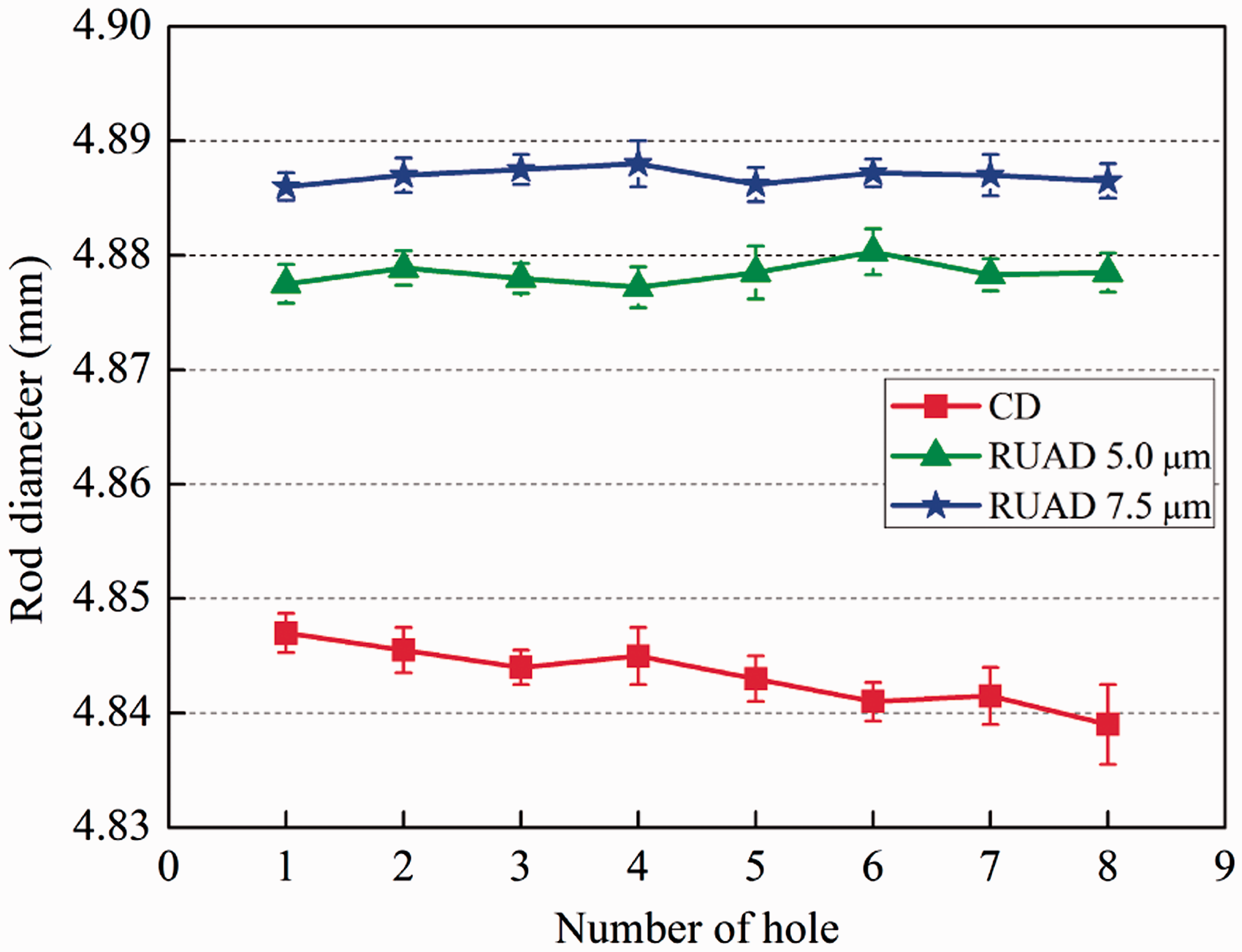
Effect of RUAD on mean thrust force. CD: conventional drilling; RUAD: rotary ultrasonic-assisted drilling. Effect of RUAD on maximum cutting temperature. CD: conventional drilling; RUAD: rotary ultrasonic-assisted drilling. Effect of RUAD on mean surface roughness. CD: conventional drilling; RUAD: rotary ultrasonic-assisted drilling. Effect of RUAD on machined hole diameter. CD: conventional drilling; RUAD: rotary ultrasonic-assisted drilling. Effect of RUAD on machined rod diameter. CD: conventional drilling; RUAD: rotary ultrasonic-assisted drilling.
Effect of RUAD on the mean thrust force
In Figure 9, each data point was the mean value of thrust force in stable drilling stage for each hole. It can be seen from the graph that the mean thrust force of RUAD was significantly lower than that of CD, and the mean thrust forces of RUAD decrease with the increase of vibration amplitudes from 5.0 to 7.5 µm. The reasons could be that the ultrasonic impact and additional ultrasonic vibration velocity VF during RUAD enhanced the tool cutting ability so as to remove the workpiece material easily and acquire high material removal rate, as well as the ultrasonic separated intermittent cutting process of abrasives at the tool end face greatly lowered the friction effect.
Figure 9 also shows that the mean thrust forces of CD increase with the increase of drilled hole because of the chip adhesion of tool surface, while the mean thrust force curves were more stable in RUAD with 5.0 and 7.5 µm than that in CD. The reasons could be that chip adhesion occurred to the tool during CD, which rapidly decreased the tool cutting ability so that obviously increased the mean thrust forces of CD; however, slight abrasive wear occurred to the tool during RUAD with 5.0 and 7.5 µm, but this was few influences on the tool cutting ability so that slightly changed the mean thrust forces of RUAD with 5.0 and 7.5 µm.
In addition, the delamination of drilled CFRP hole was easily induced with the increase of thrust force, which also indicated that the delamination was prone to occur to CD of CFRP.
Effect of RUAD on the maximum cutting temperature near the drilled hole exit
As shown in Figure 10, it can be observed that the maximum cutting temperatures near the drilled hole exit during RUAD were remarkably lower than that during CD, and the temperatures of RUAD decrease as the increase of vibration amplitudes from 5.0 to 7.5 µm. The major reasons for that were as follows. Firstly, owing to the cutting temperature in drilling process of CFRP came mainly from the cutting zone between tool end face (i.e. main cutting edge) and hole bottom, as well as due to the intermittent cutting mode of separation and contact between the tool end face and hole bottom during RUAD, which greatly improved the removal effects of chip and heat conduction and reduced the friction effect. Secondly, owing to the tool cutting ability of RUAD was enhanced by ultrasonic impact action and additional ultrasonic vibration velocity VF, which made tool easy to cut-off fibers and epoxy. Therefore, the cutting temperature of RUAD could be decreased significantly compared to that of CD, which held to reduce the chip adhesion of tool surface.
Furthermore, seen from the diagram, the temperatures of CD increase with the rise of drilled hole, while the temperature curves were more steady in RUAD with 5.0 and 7.5 µm than that in CD. The reasons could be explained by that tool abrasive wear and chip adhesion changed the tool cutting ability so as to cause the apparent change in cutting temperature, and the influence of chip adhesion on tool cutting ability was significantly larger than tool abrasive wear. Seen from Figure 10, the maximum value of cutting temperature in CD of CFRP during the eighth drilled holes reached 203℃ that close to the critical temperature 250℃ of drilled hole,41,42 and Figure 8(a) shows the diamond abrasives of tool surface adhered by chip completely (i.e. losing the tool cutting ability), so this marked the termination of tool life.
Effect of RUAD on the mean surface roughness of drilled hole
The surface roughness of drilled hole was also obtained by the surface profilometer, and each data point as shown in Figure 11 was the mean value of surface roughness in four measurements for each hole. In the diagram, the error bars represent the data distribution of measured values from four measurements for each hole. The following results can be drawn from Figure 11. Firstly, the mean values of surface roughness after RUAD are evidently lower than CD, and the mean values after RUAD reduce with the increment of vibration amplitude from 5.0 to 7.5 µm. Secondly, the mean values after CD augment with the increase in drilled hole number, while the changes of surface roughness curves are slighter in RUAD with 5.0 and 7.5 µm than that in CD. Therefore, it was clear that the surface finish of drilled holes in RUAD was further improved compared with that in CD. This could be explained by that excellent removal effect of chip, ultrasonic smoothing effect of machined surface and enhanced tool cutting ability in RUAD were generated, which smoothed the machined surface morphology heights and obtained flat machined surface.
Effect of RUAD on machined hole diameter
The machined hole diameters of CFRP were measured by a digimatic dial indicator (model MarCator 1086R, Mahr Corp., Germany) that used in hole measurement, and three measurements were implemented with different positions for each hole, the average of three measured values for each hole was used as shown in Figure 12. The hole diameters of RUAD with vibration amplitudes of 5.0 and 7.5 µm were much closer to the standard hole diameter (i.e. ϕ7.5 mm) than that of CD. Besides, it is also found that, with the increase of drilled hole, the hole diameters became larger gradually in CD than that in RUAD with 5.0 and 7.5 µm.
The reasons for the above results were as follows. Firstly, the removal effect of chip in CD was worse than that in RUAD with 5.0 and 7.5 µm. Secondly, many chips jammed into the cutting zones (i.e. including between the tool outside surface and hole inwall, as well as between the tool end face and hole bottom) because of the poor removal effect of chip, which led to the chip adhered to diamond abrasives of tool outside surface and end face, the decrement of tool cutting ability, the increase of outside radial extrusion force and thrust force, and the rise of cutting temperature. Thirdly, the chip adhesion of tool outside surface became increasingly serious as the rise of cutting temperature, which gradually reduced the tool cutting ability and removal effect of chip, increasingly enhanced the outside radial extrusion force and thrust force. Therefore, the hole diameters became large and outside chip jamming became serious gradually as the increase of outside radial extrusion force, in other words, the increased outside radial extrusion force aggravated the expansion of drilled hole diameter and chip adhesion.
Effect of RUAD on machined rod diameter
The machined rod diameters of CFRP were measured by a digimatic external micrometer (model IP 65, Mitutoyo Corp., Japan), and three measurements were carried out with various positions for each rod, the average of three measured values for each rod was used as depicted in Figure 13. The rod diameters of RUAD with 5.0 and 7.5 µm vibration amplitudes were greater than that of CD as well as less than the standard rod diameter (i.e. ϕ4.9 mm). Furthermore, with the increase of drilled hole, the rod diameters became smaller slowly in CD compared to that in RUAD with 5.0 and 7.5 µm.
The reasons for the above results were as follows. Firstly, the removal effect of chip in CD was worse than that in RUAD with 5.0 and 7.5 µm. Secondly, many chip jammed into the cutting zones (i.e. including between the tool inside surface and rod outside surface, as well as between the tool end face and hole bottom) due to the poor removal effect of chip, which caused the chip adhered to diamond abrasives of tool inside surface and end face, the decrement of tool cutting ability, the increase of inside radial extrusion force and thrust force, and the rise of cutting temperature. Thirdly, the chip adhesion of tool inside surface became increasingly serious as the rise of cutting temperature, which gradually reduced the tool cutting ability and removal effect of chip, increasingly enhanced the inside radial extrusion force and thrust force. Therefore, the rod diameters became small and the jamming of rod and chip became serious gradually as the increase of inside radial extrusion force, that was to say, the increased inside radial extrusion force aggravated the contraction of rod diameter and chip adhesion, which made the machined rod difficult to remove.
Effects of RUAD on tool wear
The surface conditions of core drill tool end face and lateral face in CD and RUAD after the eighth drilled holes were observed using a digital optical microscope (Nikon E950 by Nikon Co., Ltd.), as shown in Figures 14 and 15.
Microscopic images of tool end face for CD and RUAD after the eighth drilled holes. (a) CD, (b) RUAD 5.0 µm, and (c) RUAD 7.5 µm. Microscopic images of tool lateral face for CD and RUAD after the eighth drilled holes. (a) CD, (b) RUAD 5.0 µm, and (c) RUAD 7.5 µm.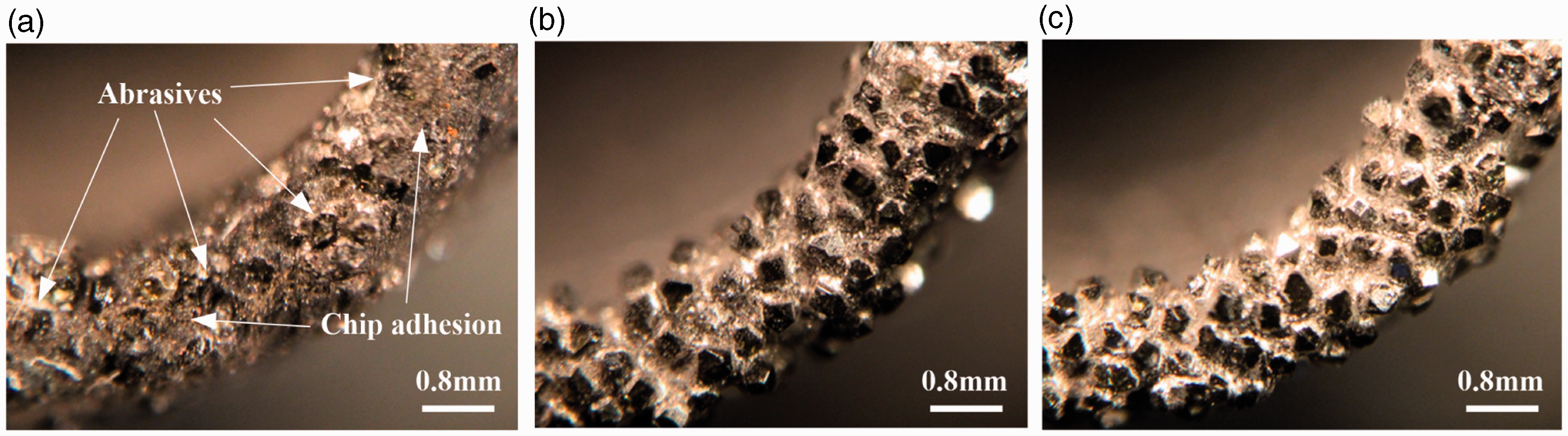
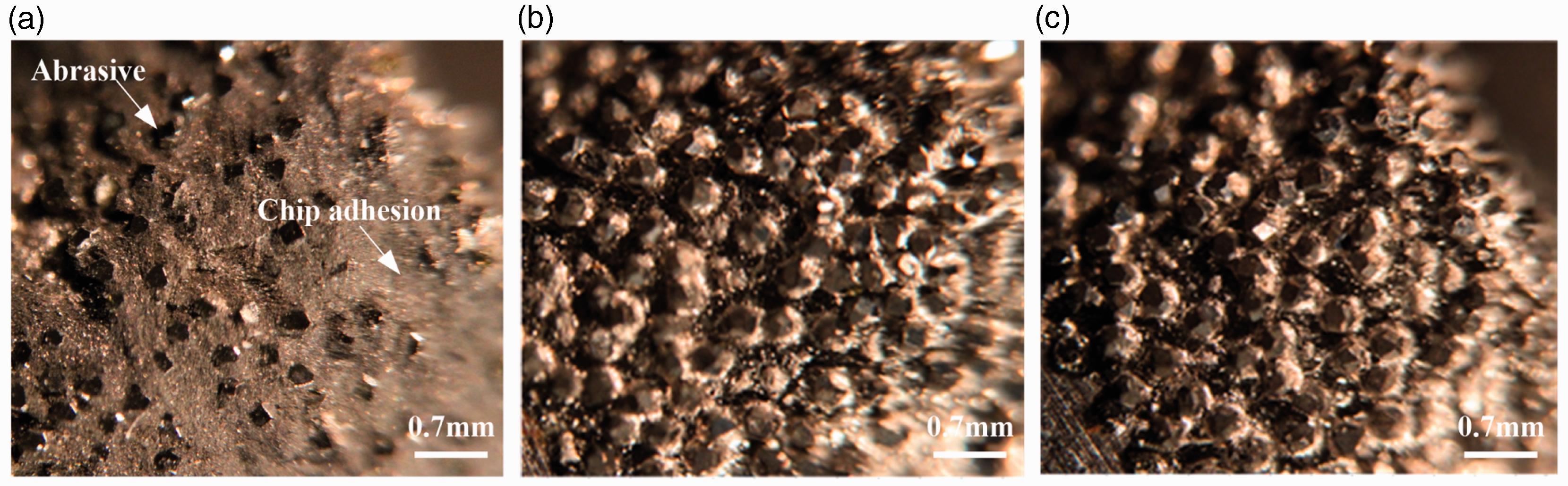
It can be seen from Figures 14 and 15 that the abrasives of tool end face and lateral face in CD had been almost completely adhered by chip compared to that in RUAD with 5.0 and 7.5 µm. Meanwhile, the phenomenons of abrasives pullout and fracture were not occurred in CD and RUAD with 5.0 and 7.5 µm. Besides, the degree of wear of tool surface abrasives was few visible changes both in CD and RUAD with 5.0 and 7.5 µm, i.e. these diamond abrasives of tool surface were still sharp.
These results were sufficient to prove that the former analyses about the failure modes of core drill tool during CD and RUAD were right, i.e. the main failure mode of core drill tool during CD and RUAD of CFRP without coolant was the adhesive failure and abrasive wear failure, respectively.
Effects of RUAD on surface integrity of drilled hole
The surface integrity of hole at different locations for CD and RUAD after the first, fifth, and eighth drilled holes was observed using a digital optical microscope (Nikon E950 by Nikon Co., Ltd.), as shown in Figures 16 to 18.
Surface integrity of hole at different locations for CD and RUAD after the first drilled holes. (a) CD, (b) RUAD 5.0 µm, and (c) RUAD 7.5 µm. Surface integrity of hole at different locations for CD and RUAD after the fifth drilled holes. (a) CD, (b) RUAD 5.0 µm, and (c) RUAD 7.5 µm. Surface integrity of hole at different locations for CD and RUAD after the eighth drilled holes. (a) CD, (b) RUAD 5.0 µm, and (c) RUAD 7.5 µm.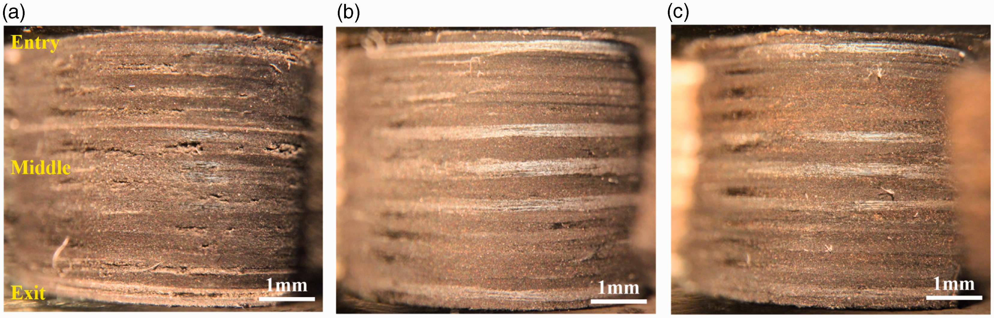
Seen from Figures 16 to 18, obvious machining defects consisted of matrix damage, delamination and rough surface were observed in CD, meanwhile, the machining defects became serious with the increase of drilled hole number from the first to the eighth. The reasons for this results were attributed to the poor chip removal condition, inferior tool cutting abilities, and serious chip adhesion of tool surface during CD, which led to a large number of chips of carbon fiber and epoxy resin were involved in the cutting process of CFRP so as to bring about the extra friction or grinding and unstable cutting process or surface integrity of drilled hole. However, seen from the first drilled hole to the eighth drilled hole in RUAD with 5.0 and 7.5 µm, the drilled hole surfaces both were flat or smooth and no obvious machining defects, meanwhile, the surface integrities of drilled holes in RUAD with 7.5 µm were slightly better than that in RUAD with 5.0 µm. The superior results could be put down to the ultrasonic separated intermittent impulse cutting characteristics, ultrasonic self-cleaning function, and ultrasonic smoothing effect, which improved the chip removal effect and enhanced the tool cutting abilities during RUAD. In addition, owing to the poor chip removal condition, inferior tool cutting abilities, high cutting temperature, and chip adhesion during CD, it can also be found that the surface gloss and finish of drilled holes in CD both were much worse than that in RUAD with 5.0 and 7.5 µm. As a result, in comparison with the superior cutting conductions during RUAD of CFRP, the delamination and matrix damage of drilled CFRP hole were easily occurred in CD because of the poor cutting conductions and action of increasing thrust force during CD of CFRP.
The microscopic surface morphologies of drilled holes and fibers fracture surfaces in CD and RUAD with the vibration amplitude of 5.0 and 7.5 µm were observed by means of a scanning electron microscope, as shown in Figure 19.
SEM micrographs of the drilled hole surfaces and fibers fracture surfaces in CD and RUAD. (a) CD, (b) RUAD with the vibration amplitude of 5.0 µm, and (c) RUAD with the vibration amplitude of 7.5 µm.
Seen from Figure 19, it can be observed that the drilled hole surfaces and the fibers fracture surfaces of RUAD were more flat than that of CD, meanwhile, the drilled hole surfaces and the fibers fracture surfaces during RUAD became more flat with the increase of vibration amplitudes from 5.0 to 7.5 µm, while the serious chip adhesion and surface pit or groove occurred to the drilled hole surface in CD as well as the concavo-convex fracture surfaces and serious surface tearing occurred to the fibers fracture surfaces in CD. The reasons could be that the tool cutting ability was enhanced during RUAD so as to easily cut-off fibers and epoxy, as well as the ultrasonic smoothing effect was produced to smooth the machined surface morphology heights during RUAD. Besides, the superior removal effects of chip and rod were obtained during RUAD due to the excellent ultrasonic-separated intermittent cutting characteristics and ultrasonic self-cleaning function of RUAD, which obviously reduced the chip adhesion and roughness of drilled hole surface in RUAD compared with that in CD.
Based on the above analyses, it can also be found from the micrographs that the fiber fracture mode in RUAD was mainly the shear fracture, while the fiber fracture mode in CD was primarily the tensile fracture. The detailed reasons for the results were as follows. Firstly, the excellent removal effects of chip and rod during RUAD (i.e. ultrasonic self-cleaning function) maintained the tool cutting ability, meanwhile, the ultrasonic separated intermittent cutting characteristics of RUAD changed the static cutting process of CD as well as enhanced the tool sharpness and cutting ability, which made it easier to cut off the carbon fibers and epoxy resin so as to achieve more flat fibers fracture surfaces. Secondly, due to the constant contact between tool end face and hole bottom during CD, the poor removal effects of chip and rod and the inferior heat conduction were occurred in CD, i.e. led to the abrasives of tool end face and lateral surface adhered by chip easily under the action of thrust force, which would greatly lower the tool cutting ability, increase the friction effect of contact interface between tool surface and contact surface of workpiece, and then increase the thrust force and cutting temperature, thus it would be fairly difficult to cut off the carbon fibers and epoxy resin so as to obtain poor fibers fracture surfaces and hole surface integrity under the inferior cutting conditions.
Conclusions
This paper reported a study on the removal analyses of chip and rod in RUAD of CFRP using core drill under no cooling condition. Based on the theoretical analysis and experimental results, the following conclusions can be drawn from this study.
The ultrasonic self-cleaning function and longitudinal ultrasonic smoothing effect can be attained during RUAD, which effectively improve the removal effects of chip and rod, prolong the tool life, and enhance the surface integrity and machining precision of drilled hole. Compared with CD of CFRP, the RUAD with 5.0 and 7.5 µm obviously reduces the chip adhesion, rod jamming, rod fragmentation, thrust force, cutting temperature, surface roughness, expansion of drilled hole diameter, and contraction of machined rod. Meanwhile, the RUAD with 5.0 and 7.5 µm significantly enhances the tool cutting ability and sharpness, which make it easier to cut off the carbon fibers and epoxy resin so as to achieve more flat fibers fracture surfaces. The diameters of machined hole and rod in RUAD with 5.0 and 7.5 µm are much closer to their standard diameters than that in CD. The fiber fracture mode in CD and RUAD is mainly the tensile fracture and shear fracture, respectively. The main failure mode of core drill tool during CD and RUAD of CFRP without coolant is the adhesive failure (i.e. the chip adhesion of diamond abrasives at tool surface) and the abrasive wear failure (i.e. the wear of diamond abrasives at tool surface), respectively. In addition, when the diamond abrasives of tool surface are completely covered and adhered by chip, the tool cutting ability will lose completely and the tool life should be terminated.
Highlights
This paper reports in detail a study on removal analyses of chip and rod in RUAD of CFRP using core drill under no cooling condition for the first time. The principle analysis on RUAD of CFRP is described and the 3D cutting process models for RUAD and CD of CFRP are established, respectively. A novel ultrasonic vibration air drill is developed and used in experiments first, as well as the experimental platforms are designed and set up. The ultrasonic self-cleaning function and longitudinal ultrasonic smoothing effect can be attained during RUAD, which effectively improve the removal effects of chip and rod, prolong the tool life, and enhance the surface integrity and machining precision of drilled hole. Compared with CD of CFRP, the RUAD with 5.0 and 7.5 µm obviously reduces the chip adhesion, rod jamming, rod fragmentation, thrust force, cutting temperature, surface roughness, expansion of drilled hole diameter, and contraction of machined rod. The diameters of machined hole and rod in RUAD with 5.0 and 7.5 µm are much closer to their standard diameters than that in CD. The main failure mode of core drill tool during CD and RUAD of CFRP without coolant is the adhesive failure and abrasive wear failure, respectively. The RUAD significantly enhances the tool cutting ability and sharpness so that it is easier to cut off the carbon fibers and achieve more flat fibers fracture surfaces. The fiber fracture mode in CD and RUAD is mainly the tensile fracture and shear fracture, respectively.
Footnotes
Declaration of Conflicting Interests
The author(s) declared no potential conflicts of interest with respect to the research, authorship, and/or publication of this article.
Funding
The author(s) received no financial support for the research, authorship, and/or publication of this article.