
Abstract
Adhesive bonding is usually used to fabricate composite structures that are hard to manufacture in one piece, however, their lightweight advantage is usually impaired by low failure strength. For high performance composite structures, bonding properties of joints dominate the failure performance and commonly are the primary target of structural optimization. Both experimental and numerical studies of failure behavior of single-lap joints with three-dimensional braided composite laminate adherends are presented in this paper. First, tensile failure tests were performed on braid-laminates single-lap joints bonded with epoxy resin. Compared with the laminates–laminates single-lap joints, the failure load of the braid–laminates single-lap joints increased by 18.4%. Then, the Finite Element Method (FEM) coupled with cohesive zone models (CZM), considering different value of overlap length (L), was used to perform the detail stress distribution of the overlap sections of SLJs. Further, damage initialization and crack growth of single-lap joints are analyzed in detail to fully characterize the failure process, and both experimental and numerical results lead to the same conclusion. Lastly, the effect of three-dimensional braided adherends’ braiding angle on braid-laminates single-lap joints’ performance was investigated, which provides suggestions for the design and optimization for adhesive bonded composite structures.
Introduction
Three-dimensional (3-D) braided composites have outstanding mechanical properties and have been widely used in aeronautic and astronautic industries. Compared with conventional laminated composites, 3-D braided composites overcome the delamination problem and provide superior multi-directional bearing capacity and outstanding impact and fatigue resistance. However, in many practical applications, near net shape manufacturing could be tricky. Therefore, most structures are manufactured by joining different parts at the final stage. There are two types of commonly used joining methods for composite structures: (1) mechanical fastening and (2) adhesive bonding. For mechanical fastening, a number of holes have to be machined in the composite parts and may cause structural damage due to fiber rupture and stress concentration. Comparatively, adhesive bonding is more efficient than mechanical fastening because the load transfer between adjacent parts is more smooth.
In the last few decades, extensive experimental investigation and theoretical analyses of composites bonded joints have been conducted and significant achievements have been made. Researchers have investigated the effect of various parameters on failure behaviors of composite bonded joints, such as adhesive fillet, thickness, bonding length, etc. Kim et al. 1 investigated the influence of different bonding methods on the failure mode and strength of composite single-lap bonded joints. It was demonstrated that the failure strength is not always proportional to the adhesion strength of the adhesive due to the weakness of delamination in adherends. Neto et al. 2 investigated the failure in adhesive joints with composites of different characteristics, and found reliable ways to predict their properties. It is shown that the failure process and strength of adhesive joints with different adhesive properties (ductile and brittle) had different results. da Silva and Adams 3 studied the case of a double-lap joint that consists of two adhesives, one for −55℃ and the other for 200℃. They showed that this technique enables the design of a joint with a higher load capacity than a joint with only one adhesive, especially for dissimilar adherends. Tsai et al. 4 investigated the effect of a spew fillet on adhesive stress distributions in laminates–laminates SLJs. They pointed out that adhesive shear and peel strain (stress) concentrations can be reduced greatly by introducing a fillet at the end of the overlap, and these concentrations are affected by the geometrically nonlinear deformation of the single-lap joint. Olajide et al. 5 investigated the airworthiness to bonded repairs for primary aircraft structures and developed a methodology to control manufacturing defects including porosity, unbonded area, adhesive thickness and flatness variation of bonding region. To evaluate the effectiveness of the developed methodology, fatigue tests were conducted and uncertainty of the results was analyzed. It was noted that these defects and anomalies have significant influences on the fatigue life and related uncertainty of bonded joints, but a minimal effect on their static strength. Mazumdar et al. 6 studied the static and fatigue behavior of adhesive joints with sheet molding compound composite adherends. The results indicated that the static behavior of adhesive joints is significantly influenced by the lap length and adhesive thickness, and the joint failure load was shown to increase with the overlap length or adhesive thickness. Li et al. 7 studied the stress and strain distributions across the adhesive thickness in composite SLJs. Both tensile and shear stress at the bond free ends were shown to change dramatically across the adhesive thickness. Kayupov and Dzenis 8 developed a nonlinear finite element model for the cracked single-lap adhesive joint with laminates adherends and studied the effects of crack length, load, and adhesive layer on the joint response. It was shown that stress, energy release rate, and stress intensity factors vary nonlinearly with the crack length. The results indicated that the critical values of the energy release rates for fast crack propagation in the final stage of fatigue life were 2–3 times lower than the critical energies for the cracks propagating under quasi-static loading. Fatigue behavior and damage evolution were investigated by Quaresimin and Ricotta. 9 Other researchers have also investigated different methods to predict the failure loads of SLJs.10–15
Up to now, most investigations have been focusing on the mechanical performance and failure mechanism of SLJs made by materials of similar properties. However, work on SLJs composed of dissimilar materials is quite limited. Gültekin et al. 16 studied the experimental and numerical results of adhesively bonded hybrid single lap joint with different gemotries of lower and upper adherends subject to a four-point bending test. Three different types of SLJs were tested, using a constant thickness AA2024-T3 aluminium alloy plate as lower adherend, and composite material that had different numbers of layers and four different stacking sequences as upper adherend. Myeong-Su Seong et al. 17 studied the effects of various parameters, such as bonding pressure, overlap length, adherend thickness, and material type on the failure load and the failure mode of joints with dissimilar materials. The showed the failure mode of bonded joints with dissimilar materials was delamination of the composite adherend. One of the main observations was the discovery of a limiting value of overlap length, above which the joint strength was constant due to the limited ductility of the adhesive layer. Owens et al.18,19 studied composite-to-aluminum joints in terms of their stiffness behavior due to fractures. A theoretical model was proposed to predict both the maximum stiffness of joints and the rate of stiffness degration with crack growth. They reported that flexible adhesives significantly delay crack initiation and final failures due to their tendency to crack through a variety of mechanisms such as composite delamination and interfacial tearing, rather than pure bonding layer failure.
This paper investigated hybrid adhesively bonded single-lap joints manufactured by 3-D braided composite laminates, and the main objective of this work is to investigate the effect of 3-D braided component on the failure properties of SLJs. Compared with laminates–laminates single-lap joints (L-L SLJs), failure load was increased by 18.4%. Besides, a 3-D FEM model coupled with cohesive zone models (CZM) considering different values of overlap length (L) was established to simulate the stress distribution and the failure behavior of B-L SLJs under tensile loading. The quantitative agreement between the experiments and numerical results validated the numerical technique presented in the paper. Finally, the effect of braiding angle on the mechanical performance of B-L SLJs was investigated.
Sample description
Material property.
A B-L SLJs specimen was composed of two adherends (upper, lower). Figure 1 shows the dimensions and boundary conditions of the B-L SLJs tensile test setup. Glass/epoxy composite laminates were used as loading tabs on the specimens.
Geometry and boundary conditions of the single-lap joints.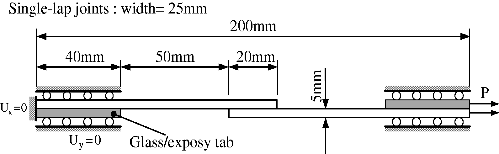
The joint specimens were tested under tensile loading using MTS 647 Testing Machine with a 100 kN load cell, at room temperature and under displacement control (2 mm/min). The gripping conditions of the specimens under tests are presented in Figure 1. The machine grips displacement and measured load were recorded to construct the load–displacement (P–δ) curves for all specimens.
Numerical model
Three-dimensional numerical models with CZM capabilities were implemented in Abaqus® to investigate stress and damage variable evolution, and strength prediction. The analyses below aim at presenting a detailed description of the joints’ failure behavior and comparative evaluations between different overlap lengths (in mm): L = 10, 20 and 30, to provide design principles for hybrid joints design. Mesh grading was applied near the overlap edges, with local refinement and in the adherends in the direction of the adhesive to account for stress concentrations, shown in Figure 2.
The mesh of the single-lap joints.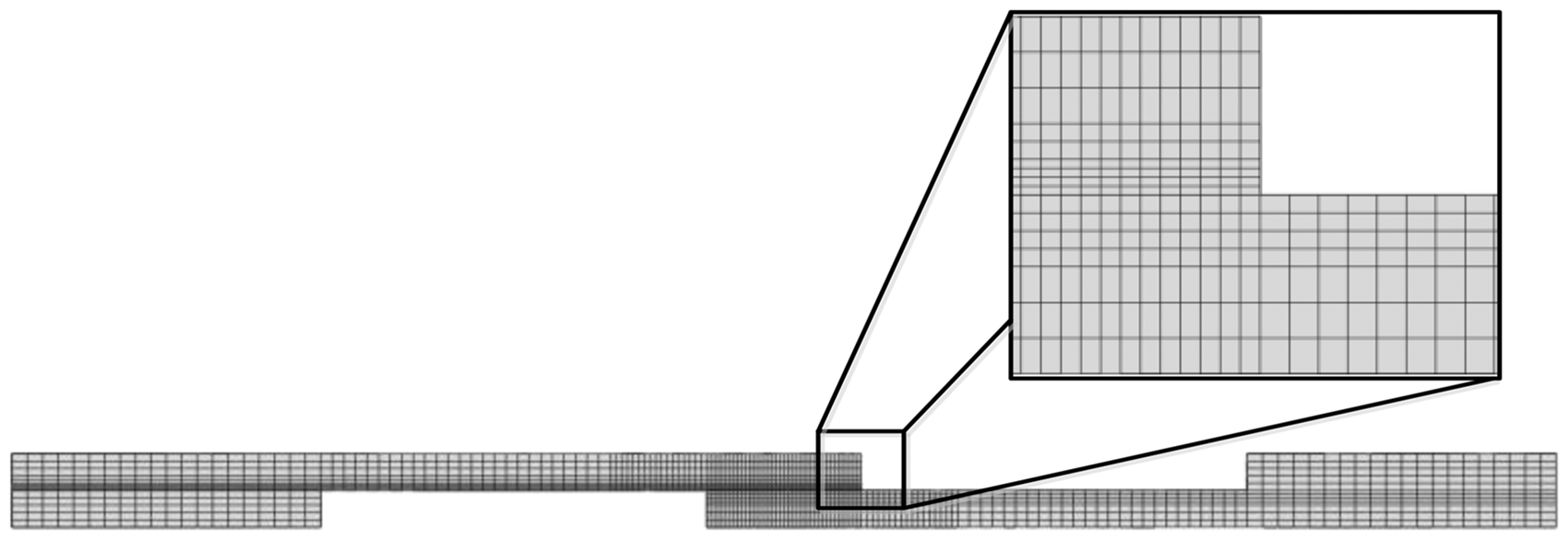
Cohesive zone model
CZM was chosen to simulate the mechanical property of interface between upper and lower adherends. It is based on fracture mechanics and does not require modeling the initial crack. Since CZM is based on elastic-plastic fracture mechanics, the stress–strain curves follow several specific relation functions, such as bilinear, trapezoidal, polynomial, exponential, and other functions.20–24
In this paper, the crack propagation was assumed to follow a bilinear behavior which is commonly used in composite materials, which defines damage initiation and damage evolution as two linear stages as depicted in Figure 3. In this figure,
Bilinear function.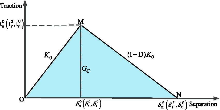
In Figure 3, OM range refers to an undamaged initiation. The stress–strain curve exhibits a linear elastic stage until the load is increased to the critical value at point M. Whether the stress limit reached or not is determined by damage initiation criteria. MN range refers to the degeneration process of the load carrying capacity after damage initiation. A damage factor D (0≤D≤1) was drawn into the stiffness coefficients, which was determined by damage evolution criteria. At Point N, D = 1 indicates a complete failure of materials.25–29 The stiffness coefficient in damage evolution is

The secondary nominal stress criterion
30
was adopted as the damage initiation criterion in this paper which describes the condition for mechanical properties to degenerate

Damage evolution criterion refers to how mechanical properties degenerate after damage initiation. There are two common criteria which are based on equivalent displacement or energy: power law and BK law. The latter one is adpated by this paper
25

Parameters of QY8911 glue film.

Modeling of 3-D braided composite laminate
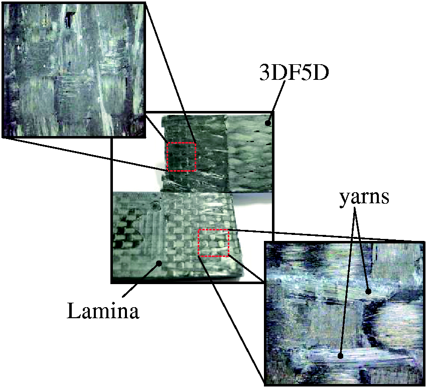
Three-dimensional braided composites can be modeled as a mixture of yarns and resin, and the yarns can be seen as unidirectional fiber bundles composed of fibers and resin. The resin is considered as isotropic linear elastic material, and the yarns are treated as transverse isotropic material. Since 3-D braided composites have periodic microstructures, a repeated unit-cell model (RUC) based on micromechanical analysis can be used to study its elastic and strength properties. Figures 4 and 5 show the braiding route and the braiding structure of three kinds of RUCs: interior, surface, and corner RUC.
Three kinds of RUCs of 3-D braided composite. (a) surface cell, (b) interior cell, and (c) corner cell. 3-D braiding route and the braiding structure.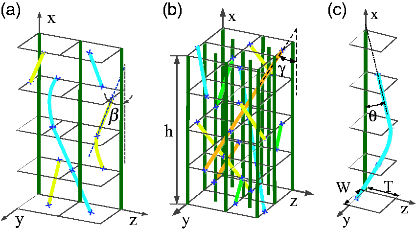
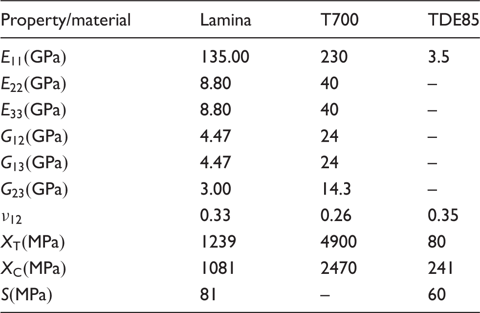
The elastic constants of unidirectional fiber composite are
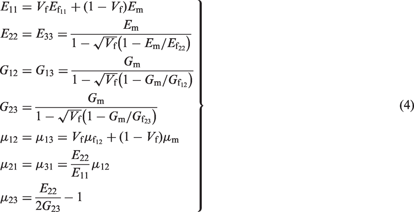
The stress–strain relationship for transverse isotropic unidirectional fiber composite in material axis direction can be written as
The fiber volume fraction has the significant effect on the mechanical properties of 3-D braided composite and takes different values in interior, surface, and corner RUC, so it needs to be calculated based on local geometric construction and distribution in all RUCs. As shown in Figure 4, γ is defined as the interior braiding angle between the interior braiding yarn axis and braiding direction, β is the surface braiding angle between the surface braiding yarn axis and the braiding direction, and θ is the corner braiding angle between the corner braiding yarn axis and the braiding direction. According to the geometrical relationship in RUCs, γ, β, and θ can be calculated from the following equations


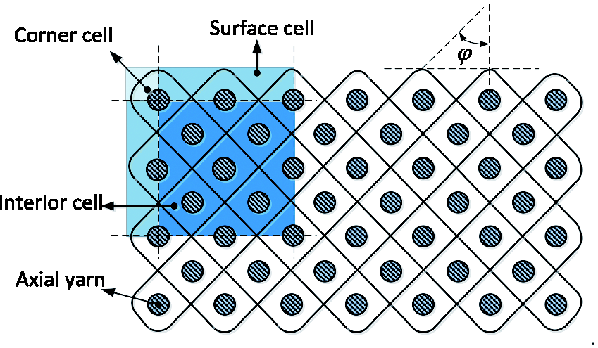
α is defined as the braiding angle between the trend of two adjacent braiding yarns axis on the preform surface and the braiding direction as shown in Figure 6. ϕ is defined as the horizontal angle between the projection of interior braiding yarn axis on transverse and the transverse direction as shown in Figure 5. T and W are the width and thickness of the corner RUC. α and ϕ can be used as control parameters and directly measured from samples, and then the interior braiding angle, surface braiding angle, and corner braiding angle can be found by the above equations.
The perform surface braiding angle.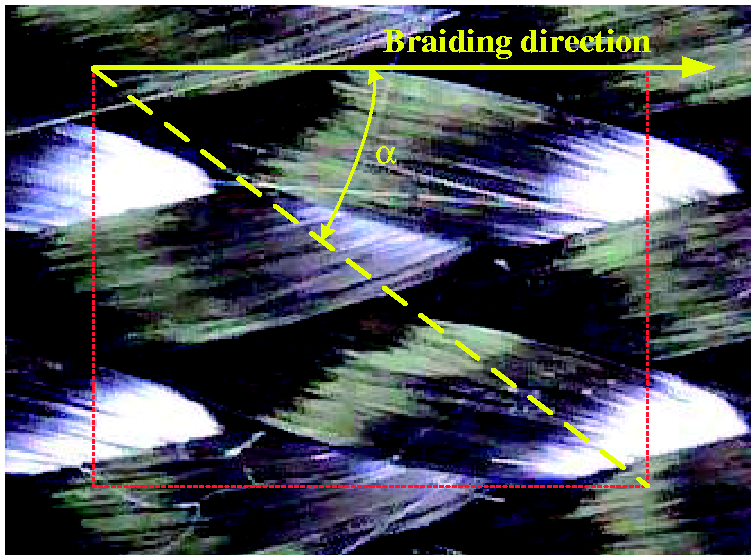
All the yarns in three RUCs can be treated as unidirectional composite bars and different types of RUC contain different kinds of spatially oriented yarns. It is necessary to calculate their volume fractions separately due to different material axes directions. The interior RUC contains one kind of axial yarns and four kinds of braiding yarns and the volume fraction of these yarns can be given by


Here,
The fiber volume fraction of interior, surface and corner RUC can be calculated by the yarn volume fraction and yarn packing factor


Since the corner RUC has only two kinds of braiding yarns, the volume fraction of corner RUC is

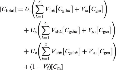
The total fiber volume fraction of braided composites can be given by the fiber volume fractions of interior, surface, and corner RUC models as follow

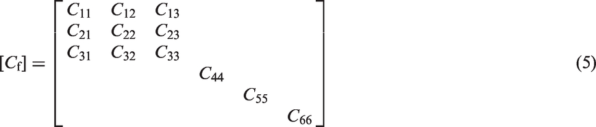
Up to now, the stiffness matrix of yarns at local material coordinate (

Here
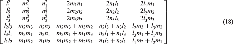
where li, mi, and ni are the cosines between the local material coordinate axes of yarns and the global coordinate axes of RUC. Finally, the total stiffness matrix of RUCs can be calculated by the volume averaging of the stiffness matrix of yarns and resin
Damage criterion
Damage criterion of composite laminates
In this paper, Hashin failure theory is used to predict the failure behavior of composite laminates. The general formulas of Hashin failure criteria are:
Longitudinal tensile failure

Longitudinal compressive failure

Transverse tensile and shear failure

Transverse compressive and shear failure

The subscripts 1 and 2 represent the fiber longitudinal and transverse direction in composite laminates.
Damage criterion of 3-D braided composite
Three-dimensional Hashin failure criterion 32 with fiber kinking failure 33 is used as damage criterion of the yarns, which categorizes the failure mechanisms into two modes: longitudinal failure and transverse failure. At the same time, to account for tensile and compressive failure in yarn longitudinal and transverse direction, two failure criterions are separately employed for different directions in the following formula.
Longitudinal tensile failure criterion is

Fiber kinking failure criterion is used for longitudinal compressive failure

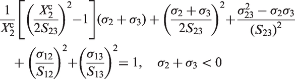
Transverse tensile and shear failure is
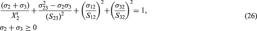
Transverse compressive and shear failure is
The resin is regarded as an isotropic material and its damage is described using maximum stress criterion, in which the tensile and compressive failure were considered. The criterion is


Damage evolution criterion of 3-D braided composite
The damage process of the material starts with appearance of micro-cracks and the material stress achieves the initial damage value. With the micro-cracks keep growing, accumulating and extending, the load capacity of the material will constantly decrease until failure. The damage state can be represented by damage variable D, D = 0 represents an undamaged state, while D = 1 means complete damage.
Three-dimensional braided filers can be treated as transverse isotropic, and the authors use

Here

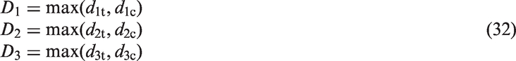
The principal direction damage values Di are defined by the damage variables di(
For the yarn along directions 1, 2, and 3
For the resin

The equivalence strain and stress of failure mode.
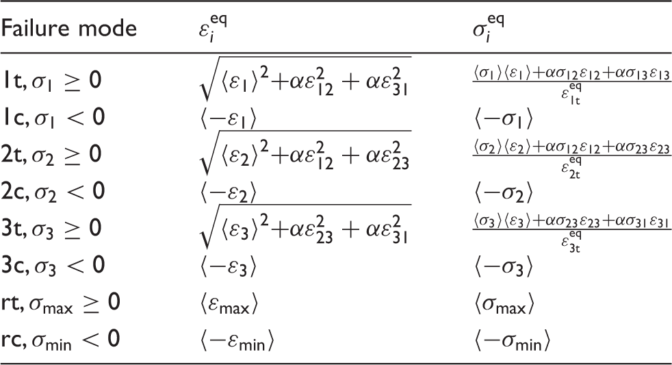
Note:
A damage criterion is established to prescribe the evolution of the damage variables for a generic damage mode as


From the hypothesis of energy identification,
36
the damaged stiffness matrix can be calculated

Results and discussions
Experimental results
In this section, three samples of B-L SLJs and L-L SLJs were tested. When the failure loads given in Figure 7 were examined, compared with the failure loads of L-L SLJs, the increase rate of failure loading for B-L SLJs was 18.4%.
The load–displacement, maximum failure load, and maximum shear stress of SLJs.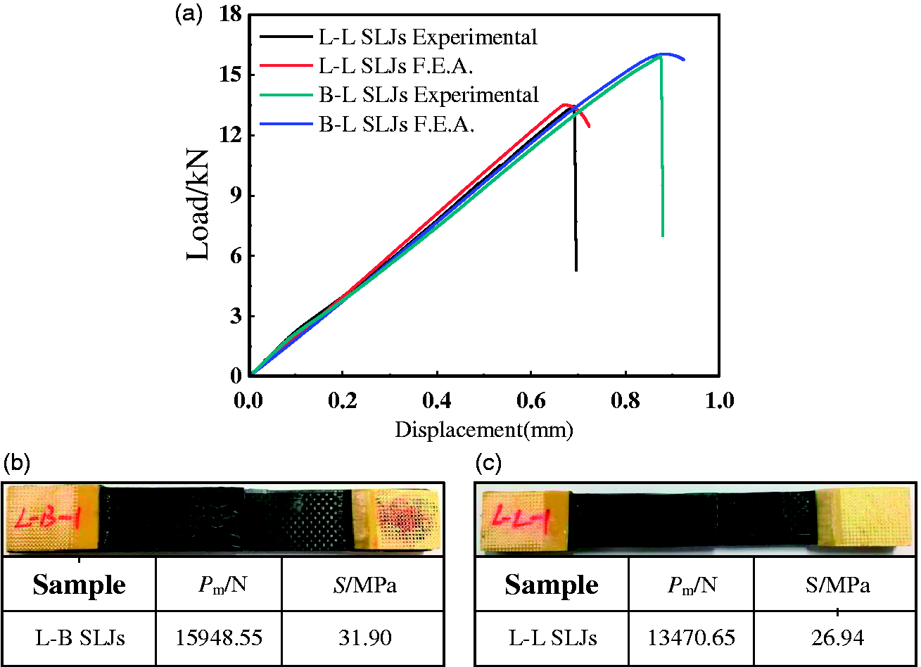
Figure 7(a) shows the load–displacement curves of experimental and finite element analysis (FEA) results of B-L SLJs and L-L SLJs. According to these graphs, the results of the experimental studies and those of finite element analyses are in close agreement with each other. As shown in Figure 7(a), both the numerical and experimental results indicate that using 3-D braided component in SLJs can effectively improve the structural loading capacity.
Figures 8 and 9 illustrate the experimental damage results of L-L SLJs and B-L SLJs. As shown in Figure 8, the results indicate that peel-off delamination in laminates is the critical failure mode of L-L SLJs. It reveals that the interlaminar mechanical property of laminates is lower than the adhesive layer. Figure 9 indicates that the adhesive interface failure is the major damage of B-L SLJs and that is one of the reasons why the loading capacity of B-L SLJs is better than L-L SLJs. In this article, in order to study the effect of 3-D braided composite on SLJs, the authors focused on the B-L SLJs.
The experimental damage of L-L SLJs. The experimental damage of B-L SLJs.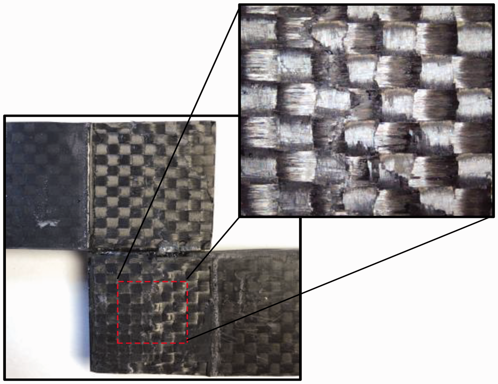
The stress distribution of B-L SLJs
In this section, through-thickness normal
The sections considered for stress analysis.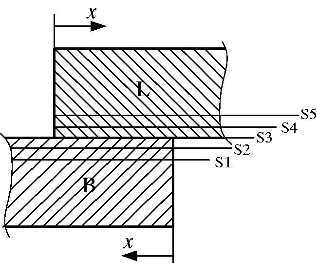
Figure 11 shows
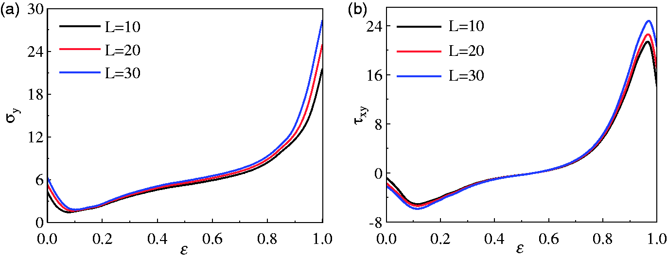
The stress distribution of overlap in SLJs: (a) peel stress
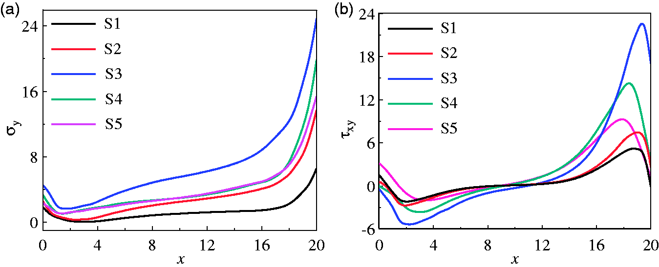
The analysis shows that
Figure 12(a) and (b) shows the
Damage analysis of B-L SLJs
Figure 13 shows Hashin and cohesive failure (SDEG) index for the damage at sections S4 and S3 under tensile loading. The curves correspond to different values of
The damage analysis of B-L SLJs.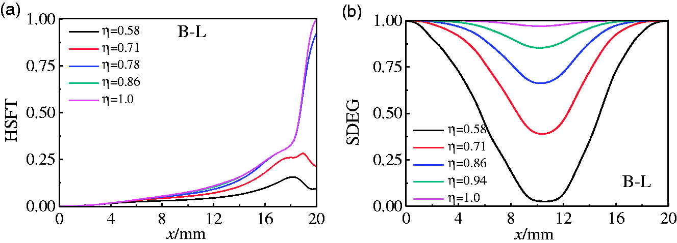
From Figure 13(a), it can be seen that damage initializes in the small area of laminate adherend near the end of overlap when
As the failure of adhesive interface is the major damage mode in B-L SLJs, to better understand the failure process, the evolution of the damage variable SDEG with δ is illustrated for L = 10 and 30 mm in Figure 14(a) and (b). The results indicate for the same value of η, the SDEG damage of adhesive interface increases with L, which is related to the positive correlation between
The SDEG damage results of B-L SLJs for L = 10 (a) and L = 30 (b).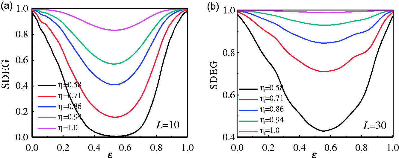
During the experiment, the upper and lower adherends of B-L SLJs bear the interfacial stress transferred by the adhesive layer. Figure 15 depicts the longitudinal fiber failure of 3-D braided composite and Hashin failure index of laminates, and the results indicate that stress concentration appears at end region of overlap where the tensile failure occurs. However, the damage coefficient of 3-D braided composite adherend is so small and remains intact during the experiment, which verifies the experiment results as shown in Figure 9. The results are attributed to the fact that the fiber of 3-D braided composites is continuum at the 3-D space and had high transverse strength, high multi-directional loading capacity, and high damage tolerance.
The damage of B-B SLJs.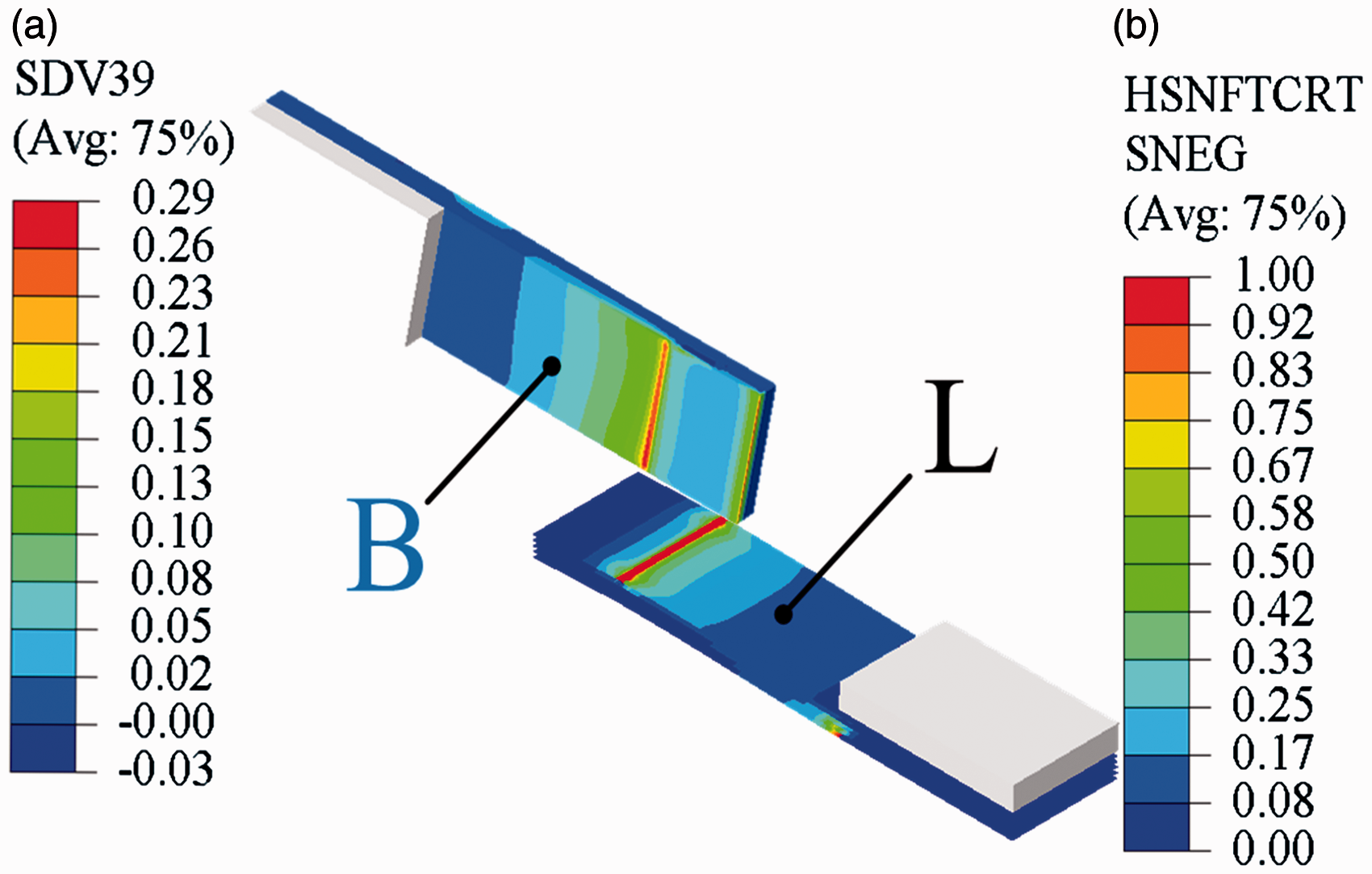
The effect of braiding angle on behavior of B-L SLJs
As the interior braiding angle and fiber volume fraction both affect the mechanical behavior of 3-D braided composite material, the paper investigated the following cases:
Effects of interior braiding angle on the mechanical parameters of braided composites.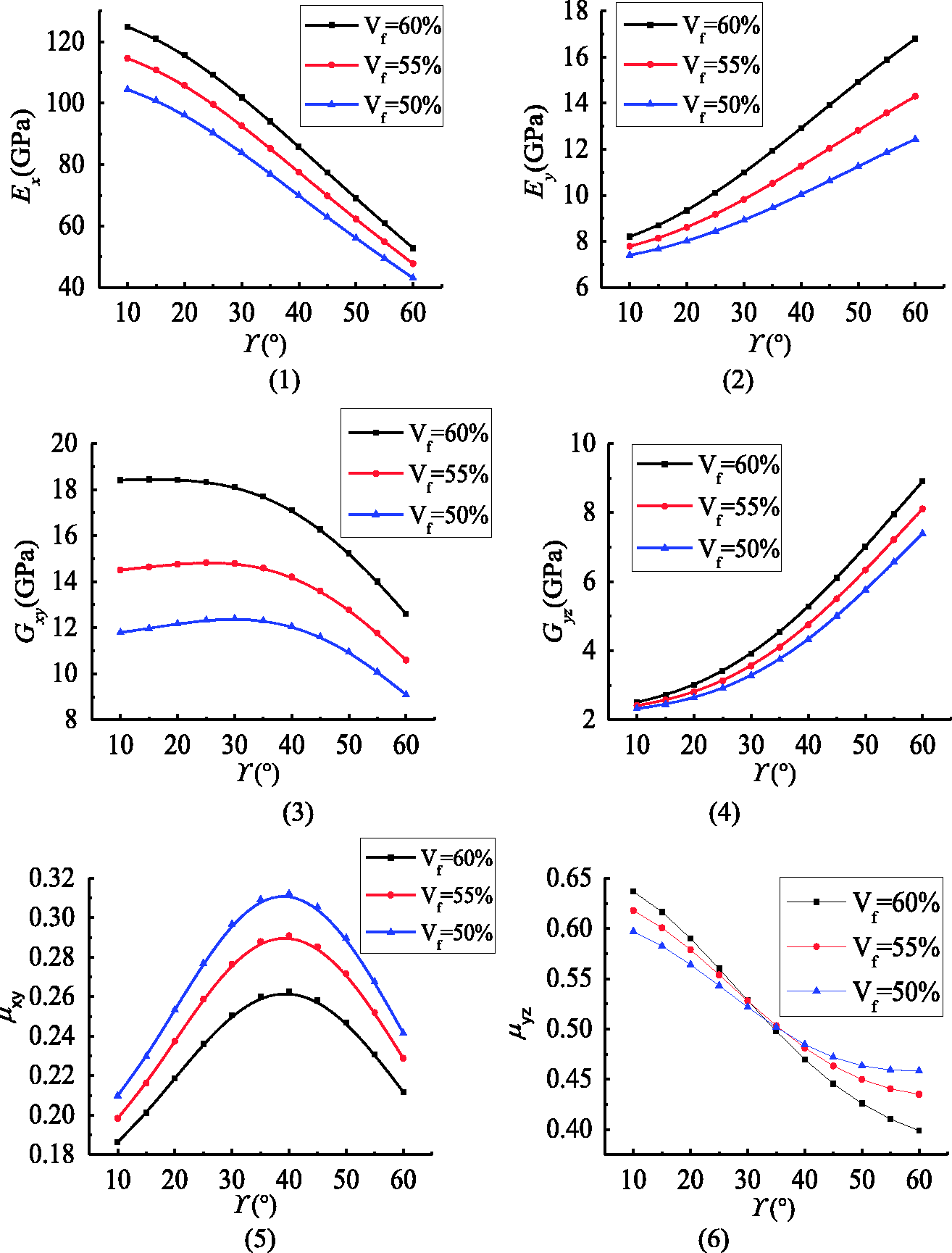
Both of the braiding angle and fiber volume fraction of 3-D braided adherend have influence on the mechanical behavior of B-L SLJs. Presented in Fig ure 17 is the influence of braiding angle with
Effect of braiding angle on the mechanical property of B-L SLJs.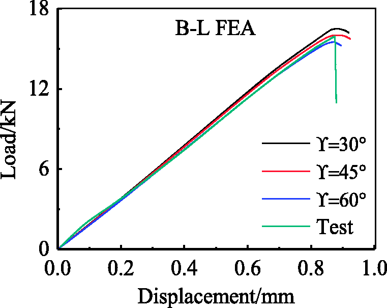
According to Figure 17, the loading capacity of B-L SLJs decreases with the increase of braiding angle. However, the effect is quite limited. This can be explained by the attribute to the limit loading capacity of adhesive interface of B-L SLJs, which dominates the loading capacity of B-L SLJs.
Conclusions
The paper studies the failure property on the adhesively bonded single-lap joints made of 3-D braided composite under tensile loading. A FEM model based on CZM was established to study the failure mechanisms of SLJs, and the numerical simulations agreed quantitatively with the experimental results. Based on these results, the following conclusions are drawn:
Compared with L-L SLJs, the failure loading of the B-L SLJs increased by18.4%. The peel-off delamination of laminates is the critical failure of L-L SLJs. That indicates that the interlaminar mechanical property of laminates is lower than the mechanical performance of TDE85 resin interface. The major damage mode of B-L SLJs is the failure of adhesive interface. The
According to Hashin failure criteria, and cohesive failure increase with δ, failure increases faster at the localized area of the overlap end region. This means damage initializes at the small area of overlap’s end of laminates’ adherend, and then propagates along the adhesive interface until complete failure of the samples, which is verified by experimental results shown in Figure 9. The SDEG value increases with L, which is related to the increase of
The increase of braiding angle only has a slight effect on the loading capacity of B-L SLJs, which could be attributed to the limited loading capacity of their adhesive interfaces.
Footnotes
Declaration of Conflicting Interests
The author(s) declared no potential conflicts of interest with respect to the research, authorship, and/or publication of this article.
Funding
The author(s) disclosed receipt of the following financial support for the research, authorship, and/or publication of this article: The authors acknowledge the support of Beijing 3-DBraiding Co., Ltd.