






Abstract
The development and recent applications of reinforced thermoplastic pipes for offshore oil and gas applications are reviewed. The design and materials of reinforced thermoplastic pipes are presented. Reinforced thermoplastic pipes have been increasingly accepted as an important alternative to traditional metallic offshore pipes due to their distinct advantages such as a higher stiffness to weight ratio, improved fatigue resistance and better corrosion resistance. Their potential applications can be extended to deep-water risers. Loading conditions which could be experienced by them for offshore applications are described. Existent studies and analyses of offshore pipes under these loading conditions are discussed. Based on this discussion, this article outlines the limitations of the current studies of reinforced thermoplastic pipes and future work to improve the analysis and design of reinforced thermoplastic pipes is recommended.
Keywords
Introduction
With the rapid development of industries and technology, the world’s energy consumption has substantially increased. In 2008, it grew to approximately 3.5 × 10¹¹ GJ with more than 70% of the total supplied by fuel from the oil and gas industry. 1 As an increasing number of offshore hydrocarbon reserves has been found, offshore oil and gas production will play a significant role in the world’s future energy supply. However, the transportation of hydrocarbon products is an important issue. Generally, offshore pipelines have been considered one of the most economical means of large-scale oil and gas transportation as they are commonly believed to be more energy efficient than other means of transportation.
Offshore pipelines first appeared in the 17th century when humans began to search for oil in offshore regions. Not surprisingly, metallic pipes have a long history of being used as offshore pipelines as their first well-known application can be tracked back to the third century in ancient Greece. 2 The first fibre-reinforced polymer (FRP) pipes, which were handmade filament-wound pipes consisting of glass fibres and resin, appeared after World War II while the development of commercial FRP pipes began in the mid-1950s and has since rapidly increased. 3 Presently, applications of FRP pipes can be found in many fields, such as civil engineering, aerospace industries and onshore and offshore crude oil and gas transportation. In the past, metallic pipes have been dominant in the offshore oil and gas industry because the unit price of their material (i.e. steel) has been much cheaper than that of a composite material. However, over the past few decades, due to the high maintenance cost resulting from the corrosion of ageing metallic pipes and the reduction in the unit price of a composite material, the costs of using FRP pipes or metallic pipes in offshore applications are comparable. Also, as FRP pipes have advantages over metallic ones (i.e. those made from high-grade steel or corrosion-resistant alloys), including a higher stiffness to weight ratio, improved fatigue resistance and better corrosion resistance, they are becoming increasingly significant in the offshore oil and gas industry. Generally, an FRP pipe can provide reliable long-term service at a relatively low cost during its design life as it has better corrosion resistance to most chemical reactions caused by oil, gas and salt water than a steel one. Depending on their offshore applications, FRP pipes deliver additional benefits; for instance, they are much lighter than steel pipes, which contributes to substantial reductions in the operational costs of existing platforms due to their low tension requirement and improved capacity to extract oil and gas from greater depths.4–6 Additionally, FRP composites can be tailored to achieve weight and flexibility optimisation for risers and flexible pipes. Recently, an increasing number of engineering projects involving FRP pipes for offshore applications has been undertaken globally, such as in the Gulf of Mexico, North Sea, Southeast Asia and Africa.
Based on structural considerations, offshore pipelines can be broadly divided into two categories: risers (drilling and production risers) and generic tubulars (flow-lines, jumpers and umbilicals, and choke and kill lines). As early as 1973, Ahlstone 7 patented a rigid FRP drilling riser consisting of glass fibres coated with epoxy. Since then, great progress has been made in the development of rigid FRP pipes8–12 and their end connections.13–18 The differences among patented designs of rigid FRP pipes include their selections of the fibre reinforcements and materials for the liner and cover. Flexible FRP pipes have also attracted considerable attention because of their installation times and costs being less than those of rigid pipes for offshore applications. In 1971, Goldsworthy and Hardesty 19 presented a method and apparatus for manufacturing continuous-length filament FRP pipes. Carter 20 described an apparatus which could be used to produce longitudinally reinforcing continuously generated plastic pipes. Sas-Jaworsky and Williams21,22 patented a design for spoolable FRP pipes and their end connections. Song and Estep23 created designs for a spoolable composite coiled tubing connector including two types of housing, which could be joined together to connect the coiled tubes. Quigley et al. 24 filed patents for a composite spoolable tube with a complicated wall structure consisting of an inner liner, interface layer, fibre composite layers, a pressure barrier and outer protective layer.
Although rigid FRP pipes have been used in offshore applications for a long time, in recent years, there has been increasing interest in flexible FRP ones as they enable faster and more cost-effective installation methods. Usually, large amounts of metallic material are used in designs of flexible FRP pipes (i.e. Carcass and Armours) with complex unbounded wall structures. Therefore, they are normally made-to-order by a few manufacturers, such as NKT Flexibles, Technip and Wellstream.25–27 This kind of flexible FRP pipe is used mainly in deep-water (≥3000 m) where it has to undergo harsh challenges, such as a high external pressure, low temperature and contact with the subsea.
A reinforced thermoplastic pipe (RTP) is a relatively new type of spoolable composite pipe. As it does not require any complicated wall structure or thermoset resins, its construction cost is less than those of other pipes while it provides an excellent combination of strength, corrosion resistance, flexibility and ruggedness. 28 It was originally developed for onshore applications such as oil gathering flow-lines and water injection lines; for instance, the Sovereign pipe (formally Halliflow™) is an early commercial RTP developed by Wellstream, 29 which has been used as an innovative pipeline technology for onshore infield flow-lines since 1989. Because of their good results in onshore applications, RTPs are now being increasingly accepted as alternative pipelines in offshore projects. In recent years, more than 500 km of RTPs have been installed in the Middle East and Southeast Asia, and interest in extending their use is still increasing in the oil and gas industry. Important manufacturers producing commercial RTPs include Airborne, Pipelife, Technip, Coflexlite and Cosmoplast. More companies will become involved in the global RTP market in future due to the commercial, operational and environmental benefits provided by RTPs.
Comparison of costs of RTP and carbon steel pipe. 29

Length of pipe = 11,500 m.
Another important benefit offered by an RTP is its spoolability, which enables it to be manufactured onshore, packed on a road-transportable reel in a long continuous form and transported to the site of the pipeline, with installation achieved by the reel-lay method, whereby it is continuously unwound from the reel and laid on the seabed. This method leads to a lower labour cost during the installation phase because most of the welding, coating and testing are accomplished onshore. 30 It is also the fastest installation method compared with other conventional ones, such as the S-lay and J-lay. In addition, the RTP’s light weight and easy installation contribute to other savings such as in barge rental rates, one of the most significant cost factors in offshore pipeline installation. Consequently, the reel-lay method provides considerable cost and scheduling advantages, including low installation costs, and ease of storage and handling. The high efficiency of RTP installation also has the additional benefit that, as it does not require any heavy equipment, it has little environmental impact.
During the past several years, RTPs have been used in offshore applications in relatively shallow water, mainly as water injection pipes and oil flow-lines. One of their important future applications is their use as gathering pipelines for relatively small offshore satellite gas fields where it is usually not commercially feasible to install a platform with gas treatment facilities. 31 Also, they could be used as risers considering their light weight and good spoolability, as well as intervention and landing/export lines.
Design and materials of RTPs
Currently, designs and qualifications of RTPs are governed mainly by industry standards and specifications. One of the most important industry standards is API RP 15S, which is the recommended practice for the qualification of spoolable reinforced plastic line pipes 32 published by the American Petroleum Institute (API). It covers the design, manufacture, qualifications and application of spoolable reinforced plastic line pipes for implementation as flow-lines in oil and gas applications, such as specifying permissible failure modes, pressure ratings and service factors. Other standards and specifications which provide guidance for designing RTPs include ANSI/API specification 5L for a line pipe, 33 API specification 15HR for a high-pressure FRP pipe, 34 offshore standard DNV-OS-F101 for a submarine pipeline system 35 and offshore standard DNV-OS-C501 for composite components. 36
The typical structure of an RTP consists of an inner thermoplastic liner, several structural reinforcing layers made from fibre-reinforced thermoplastic composites and an outer thermoplastic cover, as shown in Figure 1.
Typical structure of RTP.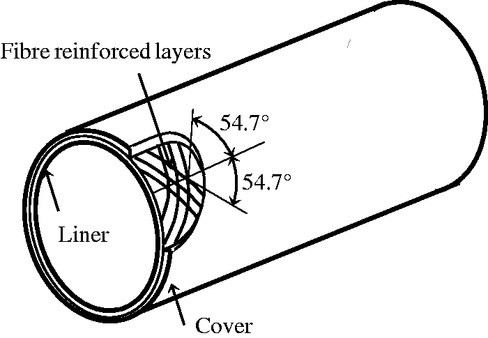
Liner and cover

PP: polypropylene; LLDPE: linear low-density polyethylene; LDPE: low-density polyethylene; MDPE: medium-density polyethylene; HDPE: high-density polyethylene; PA: polyamide; PPS: polyphenylene sulphide; PEEK: polyetheretherketone.
Reinforcing layer
The structural reinforcing of an RTP consists of several angle-ply layers made from fibre reinforcements and thermoplastic matrix materials with a winding angle of 54.7°. This winding angle is commonly adopted in the design of RTPs to fully utilise the strength properties of the fibre reinforcements in the reinforcing layers based on the ‘netting analysis’,
43
which is often used as an effective tool in the design of composite pressure vessels. However, it should be noted that this analysis is only valid when the resultant hoop to axial stress ratio is 2:1 but gives no indication of the strength of the pipe if the ratio of applied stresses varies, which can be caused by even small changes in operational conditions.
46
Obviously, the winding angles that result in the best performances of composite pipes under other loading cases could be different from 54.7°. Also, apart from structures with single winding angles of
Reinforcement materials
The reinforcements in the reinforcing layers, which are the principal load-bearing components of an RTP, can be constructed using either high-strength fibres (e.g. glass, carbon or aramid) or metallic materials (e.g. steel wires or tapes). The latter can also be classified into whiskers, metal wools (e.g. steel wool) and metal filament-length fibres, with metals such as beryllium, steel and tungsten commonly used. A beryllium reinforcement has a low density and high modulus while the density of a tungsten wire is higher. Steel wires are the most important metallic reinforcements and exhibit high and consistent strength. It has been reported that a new type of plastic-matrix steel composite pipe, a plastic pipe reinforced by cross-helically wound steel wires (PSP), has been developed in China for use in several areas, including petroleum transportation, chemical engineering and municipal water supplies. 48
Glass fibre
Glass fibres are the most widely used reinforcements in the manufacture of composite materials due to their cheap prices. Also, they have good temperature and chemical resistance, low moisture absorption and high tensile strength. Generally, there are several types of glass fibres: A-glass (A for ‘alkali’), E-glass (E for ‘electrical’), C-glass (C for ‘chemical’), D-glass and S-glass. A-glass is the original type of glass fibre, which has been almost completely replaced by other types, with E-glass the most popular because of its excellent properties and relatively low cost. As S-glass fibres are designed to possess a high strength and modulus to meet the requirements of very technical applications, such as in the aerospace and military industries, they are more expensive than E-glass. Other types of glass fibres have been developed to meet specific demands; for instance, C-glass fibres are employed mainly for surface tissue due to their good chemical resistance.
Carbon fibre
Carbon fibres are generally considered to be high-performance reinforcements with high strength and modulus but are expensive. They are produced mainly from polyacrylonitrile (PAN) heat-treated at temperatures ranging from 1000 to 3000℃, which control their tensile strength and elastic modulus, according to which they can be roughly divided into high-strength (HS) and high-modulus (HM) carbon fibres (e.g. AS4 and P75, respectively). Apart from their high strength and modulus, these fibres also improve the fatigue characteristics of FRP composites as they can reduce the strain in the polymer matrix material for a given load. 49 In addition, their low coefficient of thermal expansion (CTE) and high corrosion resistance enhance their attraction as reinforcements for FRP composites. 50 Therefore, even though applications of carbon fibre-reinforced composites (i.e. AS4-carbon fibre-PEEK) are currently limited mainly to the aerospace industry, they are increasingly being employed in offshore applications, especially those in deep water, as they can maintain their mechanical properties in seawater and provide additional cost savings in terms of weight in comparison with steel. 6 However, the impact resistance of composites reinforced by carbon fibres is not as good as that of glass fibre-reinforced composites.
Aramid fibre
Aramid is the generic name for a family of organic fibres with low density and high tensile strength. These fibres are usually produced as filament yarns, rovings or chopped fibres, all of which have a characteristic bright golden-yellow colour. They are commonly used in the military industry, especially in anti-ballistic applications, due to their light weight, and high impact and abrasion resistance; for instance, Kevlar™ is the trade name of aramid fibres manufactured by DuPont, which was originally a gunpowder producer and famous for military helmets and body armours. 51 Nevertheless, applications of aramid fibres are no longer restricted to the military industry as they are now widely used as reinforcements in RTPs for offshore oil and gas applications. Twaron™ is the brand name of Teijin Aramid, which is developing lightweight, flexible Twaron-RTPs to overcome many of the issues which affect existing steel-based pipe systems. 52
Summary of fibre properties

Matrix materials
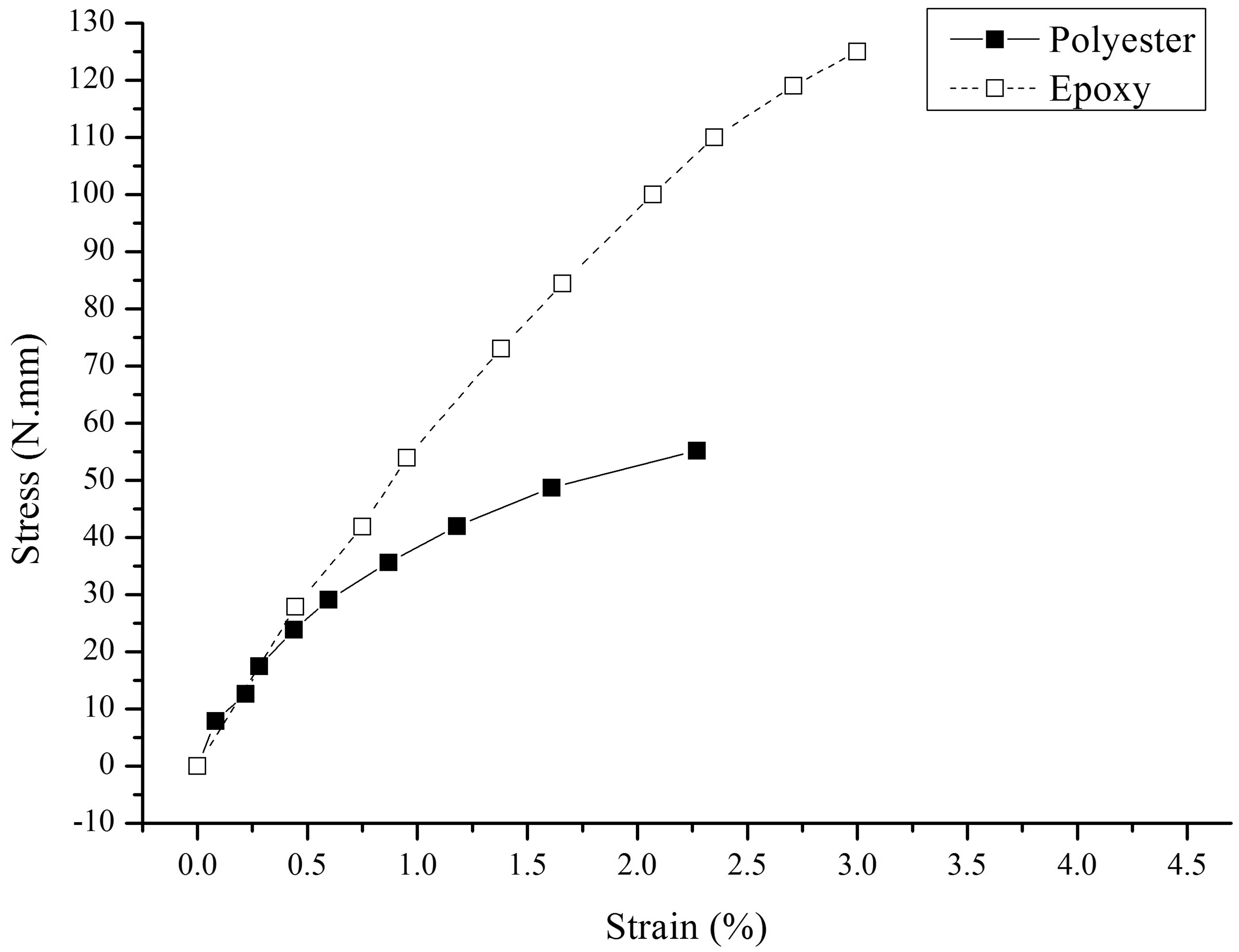
Two main classes of resins are usually used as matrix materials in FRP composites: thermoset plastics and thermoplastics. The stress–strain relationships of most thermoset plastics, such as polyester, vinylester and epoxy, are almost linear in the elastic range, as shown in Figure 2. Thus, their mechanical behaviours can be successfully described by the classic laminate theory.57,58 Due to their attractive properties, such as high chemical resistance, low processing temperatures and good fibre impregnation, thermoset plastics are commonly used matrix materials in FRP composites. However, it has been reported that glass fibre-reinforced polyester pipes show fluid weepage at about 20% of their burst pressure due to the transverse cracking of the matrix materials.
59
This brittle failure mode is commonly observed in fibre-reinforced thermosetting composites, which prevents the strength properties of the fibre reinforcements being fully utilized.
60
In contrast to fibre-RTPs, glass fibre-reinforced PE pipes can remain fluid tight up until the time of failure of the reinforcements.
61
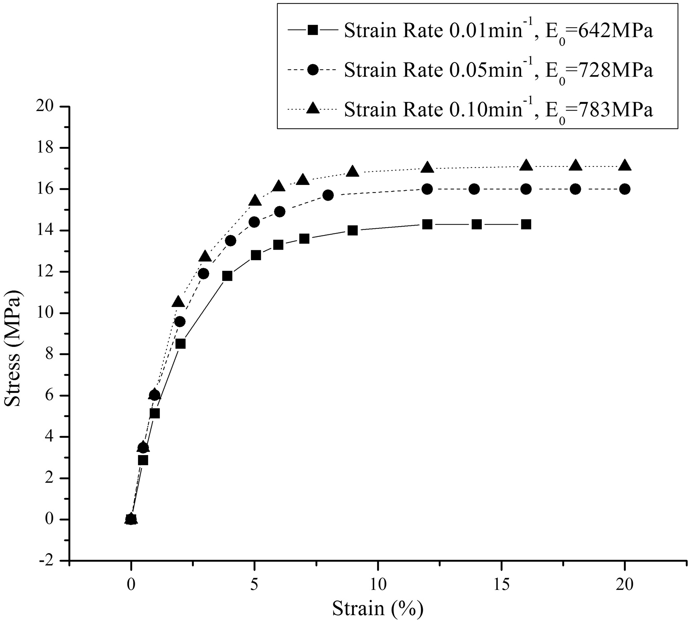
Also, in contrast to the linear stress–strain relationships of thermoset plastics, PE has shown highly nonlinear responses to loading which creates difficulties in accurately modelling its mechanical behaviours. The stress–strain curves of PE are shown in Figure 3.
Stress–strain curves of MDPE (PC2040) subjected to uniaxial loading.
61
The mechanical properties of thermoset plastics and thermoplastics during heating are also different. Thermoset plastics can retain their shape over a wide range of temperatures as their microstructure consists of an irreversible molecular chain. However, high temperatures soften thermoplastics, which harden again when cooled, a property that is important as it enables thermoplastic pipes to be repaired. 64 Also, the elastic modulus of PE changes substantially with temperature. Alawaji 65 conducted full-scale experiments to investigate the effects of temperature on HDPE pipes. According to the results, the elastic modulus of a pipe is reduced by 62% when the temperature is raised from 30 to 70℃, an almost linear decrease. Bilgin et al. 66 presented robust equations for calculating the elastic moduli of PEs (HDPE and MDPE) at different temperatures, which follow the basic trends of the data reported in the literature and experiments. They also found that the temperature has negligible effects on PE’s Poisson’s ratio and CTE.
Properties of MDPE and fibre-reinforced MDPE composites.

Current commercial RTP products for offshore applications
At present, most commercial RTPs for offshore oil and gas applications are manufactured using pipe-grade HDPE (PE 80 or PE 100) and aramid fibre reinforcements.
Pipelife RTP
SoluForce ® is the brand name of Pipelife’s RTPs, the structures of which consist of PE 100 (inner liner), aramid fibre yarns (Kevlar 29 or Twaron 1000 reinforcement layers) and PE 100 (outer cover). 72 Pipelife provides a wide range of RTPs (SoluForce Light to SoluForce Heavy), which have short-term burst pressures (STBPs) ranging from 11.5 to 45.0 MPa and a maximum ambient fluid temperature of 65℃. 73
Airborne RTP
The structures of RTPs manufactured by Airborne® use the one-material concept, that is, a pipe consists of a PE liner, E-glass fibres with a PE matrix and PE coating, which are all melt-fused to compound into a solid wall. 74 They are able to sustain a working pressure of up to 34.5 MPa at 65℃, maximum external pressure of up to 16.3 MPa at room temperature, maximum water depths for installation of up to 1629 m and have inside diameters ranging from 51 to 127 mm. 75
Coflexip RTP
Data sheet of Coflexlite® RTPs. 77

Loading conditions of RTPs for offshore applications
Classification of loads experienced by offshore pipes. 64

However, it should be noted that operational loads are usually less critical than installation loads for offshore pipes. 64 Installation loads normally depend on the installation method used, the failures caused by which are also more complex and should be investigated using different theories and methods. As some installation loads (i.e. axial tension) result in substantial plane stresses in the wall of a pipe, the failure in every lamina should be examined against a proper failure criterion, such as the maximum stress criterion, maximum strain criterion or Tsai–Wu or Tsai–Hill criteria. Other installation loads, such as external pressure, bending, torsion and their combinations, tend to lead to buckling of the whole pipe. 80
For the installation of an RTP, Bai and Bai 81 studied some properties relating to it, including its axial loading, bending loading and crushing capacities, and hydrostatic resistance. However, obviously, their research did not cover all loads which could occur in the installation phase. Therefore, a wider range of loading cases should be considered in the design and analysis of RTPs for offshore applications.
Analysis of offshore pipes under different loads
Research on offshore pipes subjected to different loads and combinations of them is active. Previous studies of the mechanical behaviours of offshore pipes under various loads, including most installation and important operational ones, are reviewed in the following subsections.
Offshore pipes under internal pressure
The load-bearing capacity of pipes under internal pressure, usually referred to as the pressure capacity, is a primary concern for designing offshore pipes. Overestimating this capacity could lead to catastrophic failures of a pipe while underestimating the amount of product that could be transported, thereby lowering production and causing extra cost. The pressure capacity of a metallic pipe is well-documented in some industrial standards82–84 and is determined mainly by its wall thickness and the yield strength of its material as:
85
Due to the anisotropy of a composite material, it is more difficult to predict the pressure capacity of a composite pipe. As described above, the ‘netting analysis’ is primarily used to design cylindrical pressure vessels and shows that winding angles of ± 54.7° are the optimum ones for closed-end composite pipes based on the assumption that only fibres carry loads. 43 Meiras 86 conducted a series of experiments using filament-wound pipes with polyester and epoxy resin to demonstrate the effect of their matrix materials on their pressure capacity. He reported a knee in the axial stress/strain curve when a pipe is subjected to internal pressure and weepage, which he attributed to resin failure before fibre breakage. Hull et al. 59 investigated failures of glass/polyester filament-wound pipes with winding angles of ±54.44° using closed-end and unrestrained-end internal pressure tests, with the experimental results agreeing well with most of the conclusions reported by Meiras. 86 Weepage resulting from transverse cracking of the resin and resin/matrix interface occurs at about 20% of its burst pressure due to fractures of the fibres. This observation was confirmed by Jones and Hull 87 who used standard microscopic technologies to examine failure mechanisms in filament-wound pipes. Then, Spencer and Hull 88 studied the influence of winding angles of ± 35°, ± 45°, ± 65° and ± 75°, on the failures of filament-wound pipes under internal pressure. It was shown that the micro-mechanisms associated with deformation, weepage and fracture depend strongly on the winding angles under both closed-end and unrestrained-end boundary conditions. Rosenow 89 extended Spencer and Hull’s study 88 to six different winding angles varying from ± 15° to ± 85° using both the classic laminate theory and an experimental approach, which showed that the optimum winding angles which lead to the highest pressure capacity depend primarily on the state of loading. From his study, winding angles of ± 55° should be used as the optimum angles for only the closed-end loading case in which the hoop-to-axial stress is 2:1, and is consistent with the ‘netting analysis’. 43 However, it should be noted that, in his experiments, even though the winding angles are set to ± 55°, the pipes still fail due to weepage before fibre breakage. Xia et al. 90 obtained similar results as filament-wound pipes with winding angles of ± 30° and ± 70° showed brittle breaking behaviours caused by transverse tensile stresses. Evans and Gibson 91 investigated the effect of the matrix materials on the optimum winding angles in more detail. They showed that the actual optimum winding angles deviate from those predicted by the ‘netting analysis’ depending on the ratio of the matrix to reinforcement stiffness. Also, Parnas and Katirci 92 demonstrated that the optimum winding angle for filament-wound composite vessels ranges from 52.1° to 54.2° depending on the geometry and failure criteria used.
Studies of the mechanical behaviours of RTPs under internal pressure have been reported in recent years. Kruijer et al. 93 developed a mathematical model based on a plane strain characterisation and conducted experiments to study the deformation behaviour of an RTP constructed of a PE liner pipe over-wrapped with two layers of non-impregnated twisted aramid cords when pressurised. The modelled hoop and axial strains showed considerable deviations from the measured values, which they suggested could be caused by the nonlinear behaviour of PE and, therefore, it is necessary to take into account material nonlinearity when modelling the mechanical behaviours of RTPs. They also indicated that the ratio between the average hoop and axial stresses is in the order of 2.25:1 for a closed-end RTP due to its geometry, which results in too much stiffness being applied in the axial direction and too little in the hoop direction when employing winding angles of ± 54.7°. Bai et al. 94 studied the burst capacity of an RTP consisting of HDPE and a combination of aramid fibre reinforcements and HDPE matrix materials under internal pressure through experimental, numerical and theoretical approaches. The values of the STBPs predicted by the numerical simulations and theoretical calculations are shown to be 19.6% and 16.5% larger than the experimental results, respectively. This is caused by not considering the nonlinear mechanical behaviour of PE in either the numerical simulation or theoretical calculation. Then, Bai et al. 95 investigated the mechanical behaviour of an RTP, the material and structure of which are similar to those of the RTP presented in Bai et al., 94 under internal pressure using a FE model, an analytical solution and experiments. In the FE model, they adopted the progressive damage model proposed by Linde et al., 96 which was originally used to model fibre-metal laminates, to determine the failure initiation and damage progression in the reinforced tapes with the HDPE modelled as a linear elastic material. The values of the burst pressure predicted by the FE model and analytical solutions are compared with the experimental results from which they show 18.1% and 26.4% deviations, respectively. It can be seen in the experiment that the orientation of the crack in the outer layer of the RTP is almost parallel to the fibre direction in the reinforced tape, which suggests that fibre breakage is the cause of failure of the entire pipe. The same results are observed in the pressure testing conducted by Gibson et al. 61 in which all specimens achieve the full strength of the reinforcements. They also demonstrated a modified laminate theory for analysing the mechanical behaviours of fibre-reinforced PE composites in which the nonlinear mechanical behaviour of the matrix materials are modelled numerically. Their approach shows reasonable agreement with most pressure-strain data from their experiments.
Offshore pipes under bending
Research on the flexural behaviour of long metallic and composite cylinders has been actively undertaken, with several studies on the reeling of metallic pipes reported in the literature.97–99 It has been shown that the minimum allowable bend radius of a metallic pipe can be limited by the elastic strain limit of the metallic material as the pipe may bend into the plastic range during the winding and unwinding processes. Brazier 100 studied the flexural behaviour of a long metallic pipe subjected to pure bending. Due to the induced bending moment, an ovalisation occurs in the cross-section of the pipe, resulting in a progressive reduction in its flexural stiffness, which is known as the Brazier effect. The pipe then buckles when the induced bending moment becomes larger than the critical moment. Kedward 101 extended Brazier’s approach to thin-walled orthotropic cylinders and presented theoretical solutions, which enable calculation of the critical moment for pipes made from orthotropic materials. Although Chan and Demirhan 102 created a closed-form solution to determine the bending stiffness of laminated composite pipes, their work was shown to be appropriate for only pipes with small diameters.
With the aid of Finite Element Analysis (FEA), Rodriguez and Ochoa 103 conducted numerical studies to analyse the flexural behaviours of carbon fibre/epoxy and glass fibre/epoxy pipes, which showed that failures of the pipes are characterised by damage initiation in their composite layers. They analysed the progressive development of damage which indicated that, as expected, epoxy-based composite pipes cannot be used as spoolable pipes as they fail easily in the brittle mode under bending. Xia et al. 104 developed analytical means of studying the stress–strain responses and deflections of filament-wound fibre-reinforced sandwich pipes subjected to pure bending but did not perform any failure modelling. Most recently, Ashraf et al. 47 presented numerical studies investigating the spoolability of RTPs made from PEEK and AS4-carbon fibre-reinforced PEEK composites. Similar to the findings from Rodriguez and Ochoa’s analysis, the spoolability of this RTP is rather limited as it fails at a large radius due to a matrix failure in the transverse direction in the fibre-reinforced layers. Although the aforementioned studies provide effective methods for evaluating the flexural behaviours of pipes, most considered the mechanical behaviours of the materials to be linear elastic.
Offshore pipes under combined bending and external pressure
In the past, RTPs have primarily been used in relatively shallow water, at depths from 30 to 900 m, due to their low resistance to external pressure as excessive external pressure results in their catastrophic collapse.
105
However, it has recently been reported that its light weight, high performance and good spoolability enable an RTP to be an ideal design for deep-water riser applications in which a pipe is expected to experience significant bending and high external pressure during its installation and operational phases.106–108 The mechanical behaviour of offshore pipes subjected to combined bending and external pressure has attracted substantial attention over the last few decades. Corona and Kyriakides109,110 investigated the collapse of long, relatively thick-walled metal pipes under combined bending and external pressure through experimental and numerical efforts, which showed that the nature of their instability and corresponding critical loads is dependent on their loading paths. Stephens et al.
111
studied the nonlinear collapse of long, cylindrical shell structures subjected to combined bending and uniform normal pressure loads. They demonstrated that the circumferential flattening of a pipe’s cross-section is the dominant collapse mode for those with higher length/radius ratios. Experimental results of collapses of aluminium and steel pipes under combined bending and external pressure were reported by Kyriakides
112
and Johns et al.
113
who showed that the nature of instability of a pipe also depends on its
Nevertheless, research results for the mechanical behaviours of composite pipes under combined bending and external pressure are limited. Starbuck and Eberle 118 developed an analytical technique for the design of spoolable composite pipes considering loading scenarios including bending strain, axial force, internal and external pressures, elevated temperature and combinations of them. Their study showed that different angle-ply laminate architectures are required for different loading scenarios to achieve better performances. Pavlou 64 also presented theoretical means of predicting the failures of composite pipes under combined bending and external pressure for design purposes. According to his research, two types of failure, material failure of the pipe wall and buckling of the structure, can occur.
Offshore pipes under combined bending and tension
As previously discussed, RTPs can be installed by the reel-lay method which involves spooling a pipe onto a transportable reel, during which it experiences significant bending in the presence of axial tension,
119
transporting the reel to the site of the pipeline and unwinding the pipe from the reel. Substantial attention has been paid to studying the responses of offshore pipes under combined bending and tension. Wilhoit and Merwin
120
presented theoretical solutions to identify the effect of axial tension on the moment-carrying capacity of a pipe. They found that axial tension reduces the pipe’s moment-carrying capability but also decreases the moment acting on the pipe. Dyau and Kyriakides
121
investigated the ovalisation in cross-sections of elastic-plastic pipes caused by combined bending and tension through a combination of experiments and theoretical analyses, which showed that it depends on the loading path, material and geometric properties of the pipe (e.g. yield strengths and
Since the use of composite pipes for offshore applications is increasing rapidly, many studies concerning the mechanical behaviours of composite pipes under the loads encountered during installation and combinations of these loads have been reported. Bai et al. 123 analysed the load-bearing capacity of an RTP under axial loads, which showed that the tearing caused by the axial tension can occur on its outside face. Most recently, the ovality of an RTP based on PE subjected to combined bending and tension was investigated by Bai et al. 124 using a theoretical method and FE simulations. Their study showed that the axial tension slows down and even reduces the ovalisation of the pipe’s cross-section. It should be noted that they studied a short RTP (20 mm), with the material nonlinearity of PE ignored in their FE model, which could have resulted in an inadequate analysis. In addition, their theoretical model was based on the model presented by Dyau and Kyriakides, 121 which was originally developed for metallic pipes. Therefore, an approach considering the plasticity of the material may not be suitable for RTPs as they will not deform plastically.
Offshore pipes under combined external pressure and tension
Except for the loads incurred during the reeling and unreeling processes, the installation of RTPs in water also adds substantial loads to the pipes. It has been shown that sections of the pipe laid on or near the seabed are subjected to a significant combination of external pressure and tension apart from bending and external hydrostatic pressure. 125
The responses of cylindrical pipes under combined external pressure and tension has been studied by many researchers for a long time. Earlier studies126–128 on the collapse of metallic pipes under combined external pressure and axial tension were developed to create design criteria for the oil-well casings recommended by API BUL 5C3.
129
They showed that the equation provided by the API recommendation provides a conservative estimate of the collapse strength. Babcock and Madhaven
130
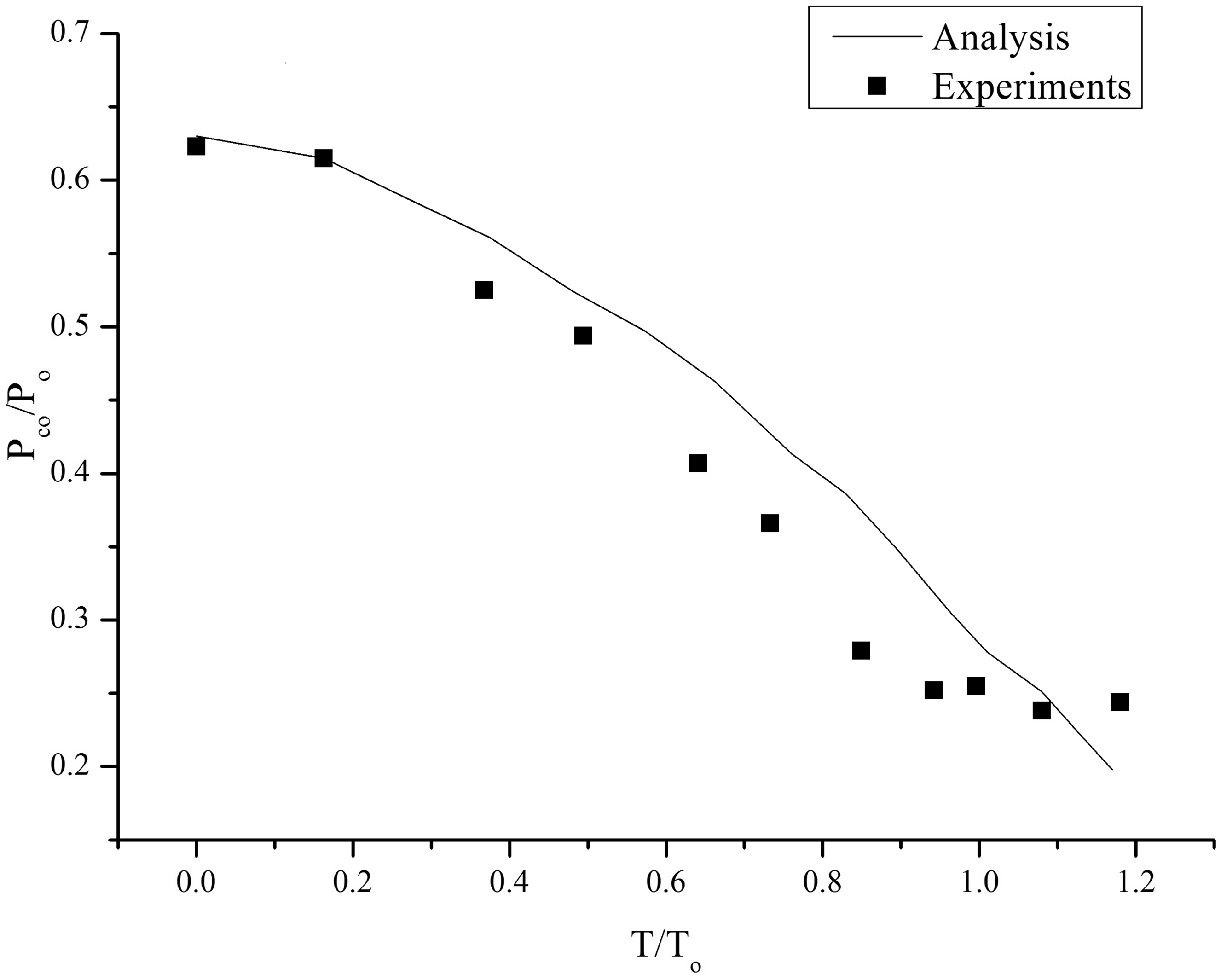
studied the collapse of a metallic pipe under combined external pressure and axial tension analytically and experimentally, and their pressure-tension interaction collapse envelope is shown in Figure 4. It is obvious that the axial tension results in a reduction in the resistance of the pipe to external pressure. Later, Madhavan et al.
131
extended their study to pipes with Pressure-tension interaction collapse envelope for pipe with D/t ratio = 25.
131
Mistry et al.
133
conducted experimental and theoretical investigations into the failure of ± 55° filament-wound glass-fibre/epoxy cylindrical pipes with
Offshore pipes under combined torsion, bending, axial tension and external pressure
The earliest publication on the mechanical behaviours of homogeneous orthotropic cylindrical shells under torsion can probably be traced back to Shaw and Simitses 137 who analysed the instability of laminated cylindrical shells under torsion. Since then, several studies investigating the torsional buckling of composite pipes have been published.138–141 As these studies considered buckling to be the most important failure mechanism when composite pipes are subjected to torsion, they focused on determining the critical load. Wall and Card 142 investigated the torsional shear strength of filament-wound glass-epoxy tubes experimentally and theoretically and, in their experiments, observed evident delamination in some specimens. Putić et al. 143 further studied the torsional properties of, and damage in, glass/epoxy composite pipes, which showed that excessive torsion can cause damage, such as fracture of the fibres and matrix delamination, which results in the appearance of cracks on the pipes and, in many cases, complete breakage of them.
With the rising demand to improve the effectiveness of aircraft structures in the aerospace industry, substantial efforts144–146 have been made to investigate the buckling and post-buckling responses of carbon fibre-reinforced polymer (CFRP) composite cylinders under combined axial tension and torsion. These studies have identified the effect of the laminate’s orientation on buckling and demonstrated that buckling loads are strongly dependent on the loading sequence. Crate et al. 147 examined the effect of internal pressure on the buckling of thin-walled cylinders under torsion and found that applying internal pressure raises the shear buckling stress. Chouchaoui148,149 conducted a similar study of a laminated cylindrical pipe under tension, torsion, bending and internal and external pressures, which roughly described some characteristics of the mechanical behaviours of the pipe under these loads. Holston et al. 150 developed a combined analytical and experimental investigation of the stability of composite cylindrical shells. They considered five loadings: (a) uniform axial compression; (b) torsion; (c) bending; (d) combined torsion and uniform axial compression and (e) combined bending and uniform axial compression. The experimental buckling loads showed 10 to 33% differences from the analytical solutions in which the effects of boundary conditions were not considered. This demonstrates the significance of taking into account boundary conditions for determining the mechanical behaviours of composites pipes under combined loadings, which could be achieved by employing FEA.
Conclusions
In this work, the development of RTPs and their applications in the offshore oil and gas industry are reviewed. Relevant design recommendations and standards which have been used in the industry at present are demonstrated. Even though these provide sufficient insight for the design, materials and structures of current RTP products, it has been found that, to enlarge their application envelope (e.g. riser), RTPs could be analysed for more complicated loads than those specified in currently used documents after reviewing loading conditions, which could be experienced by offshore pipelines.
Previous studies on the mechanical behaviours of offshore pipelines (e.g. metallic and composite ones) under aforementioned loading conditions are further reviewed. It is shown that research on the failure mechanisms of RTPs and influences of the material nonlinearity on their mechanical behaviours when subjected to these loads is limited. Therefore, more advanced analyses are required in order to improve the performance of RTPs for offshore applications.
Some work has already been done by authors of this article to fill this gap recently. The effect of the material nonlinearity of PE on the flexural behaviours of RTPs made from PE and fibre-reinforced PE composites was investigated by Yu et al.151,152 through numerical simulations which showed that disregarding the material nonlinearity of PE leads to overestimation of an RTP’s critical moment and underestimation of its flexibility. Thus, due to its material nonlinearity, an RTP can be bent to a smaller radius. Yu et al.153,154 also studied the failures of RTPs subjected to combined external pressure and bending considering the material nonlinearity, showing that buckling is the dominate mode of failure. Besides, it also has been shown that the applied axial tension decreases the load-bearing capacity of an RTP when the material nonlinearity has been taken into account. 155 The mechanical behaviours of RTPs subjected to more loading conditions, which are critical to offshore applications (e.g. internal pressure, combined external pressure and tension) were investigated in one of the authors’ (K. Yu) thesis. 156 Results obtained from this work can be used to improve the design of RTPs for offshore applications.
However, the relative lack of large-scale experimental results of RTPs subjected to different types of loads should be noted. These experimental results could not only validate the theoretical calculations and FE modelling of RTPs but also provide more real-life loading conditions and performance cases. Future studies in this area would benefit significantly from more industry contacts with manufactures and operators of RTPs.
Footnotes
Declaration of conflicting interests
The author(s) declared no potential conflicts of interest with respect to the research, authorship, and/or publication of this article.
Funding
The author(s) disclosed receipt of the following financial support for the research, authorship, and/or publication of this article: One of the authors (K. Yu) acknowledges the financial support provided by University of New South Wales (UNSW) to enable this research to be conducted.