
Abstract
In the current study, the production of multifunctional hybrid-stitched composites with improved interlaminar fracture toughness and electromagnetic interference shielding effectiveness is reported. Unidirectional carbon fiber-epoxy composite laminates stitched with Kevlar, nylon, hybrid stitched with both Kevlar and nylon and unstitched were prepared using resin infusion process. Representative specimens from unstitched and stitched composites were tested using rectangular waveguide and Mode I double cantilever beam tests. The Mode I experimental results showed that composite stitched with Kevlar exhibited the highest crack initiation interlaminar fracture toughness (GIC-initiation), whereas composite stitched with nylon exhibited the highest maximum crack propagation interlaminar fracture toughness (GIC-maximum). The four-hybrid stitching patterns exhibited higher GIC-initiation than the unstitched and stitched with nylon composites and lower than stitched with Kevlar composite, whereas they had higher GIC-maximum than the unstitched and stitched with Kevlar composites, although lower than stitched with nylon composite. The electromagnetic shielding effectiveness experimental results showed that stitched composites exhibited improved shielding effectiveness compared to unstitched composites. For example, composite stitched with nylon had highest shielding effectiveness value of 52.17 dB compared by the composite stitched with Kevlar which had 40.6 dB. The four hybrid-stitched composites exhibited similar shielding effectiveness with an average value of 32.75 dB compared to the unstitched composite shielding effectiveness of 22.84 dB. The experimental results comply with the initial goal of this study to manufacture multifunctional hybrid stitching composites with combined properties between Kevlar and nylon-stitched composites.
Keywords
Introduction
The interest in developing multifunctional materials has increased significantly in recent years due to the high demand for new materials that simultaneously perform combined structural and nonstructural functions. Composites by nature are multifunctional materials because their properties are combinations of their constituents’ properties. For example, fiber-reinforced polymer (FRP) composites can achieve simultaneous improvements in structural properties such as high specific strength, environmental stability, corrosion resistance, in-plane fracture properties and improved electromagnetic properties by incorporating conductive fillers in the matrix.1–6 However, FRPs that are used in structural applications are susceptible to delamination.
Delamination is a separation of the FRP layers when subjected to internal out-of-plane loads, due to the weaker out-of-plane properties in FRPs. Several methods have been utilized to alleviate delamination and strengthen the FRPs through-the-thickness such as stitching, tufting, z-pinning, incorporating nanofillers and 3D weaving. 7 Stitching is a well-known method in mitigating delamination, which involves stitching the dry fabrics through-the-thickness using threads with high strength and stiffness (for example, Kevlar, carbon, Dyneema, Vectran fiber) before impregnating them with resin. Stitching has proved its efficiency in mitigating delamination and improving Mode I and Mode II interlaminar fracture toughness as well as other FRPs mechanical properties such as resistance to low-velocity impact.8–12 Moreover, stitching the fabrics of larger, more complex parts together may enable assembly the multiple aircraft parts without the need of joining fasteners, resulting in reduced assembly time and fewer high stress concentration holes for the fasteners.
The remarkable properties of carbon fiber-reinforced polymer (CFRP) composites often make them the best candidate in manufacturing aircraft structures. Their widespread adoption encouraged the current study to also investigate the electromagnetic interference shielding (EMI-SE) properties of the CFRPs. This is due to the significant abundance of electronic technology in aerospace vehicles. Aircraft electronic communication and navigation systems may be adversely affected by the electromagnetic waves generated from the surrounding sources, such as the high power radars, lightning strikes, airport communication with nearby aircrafts, or even from intentionally disturbing sources in military applications. Thus, with the significant increase in the usage of electronic technology, there is an urgent need to develop aircraft structural materials with electromagnetic shielding properties to limit the amount of radiofrequency (RF) energy being intentionally or unintentionally emitted or received by the electronic devices. In this direction, there is growing research interest in investigating and improving the EMI-SE characteristics of CFRPs to become multifunctional composite materials with structural and electromagnetic shielding capabilities. Several research studies focused on improving the EMI-SE properties of CFRP by incorporating conductive fillers either by knitting, random distribution or conductive nanomaterials.13–18
Stitching CFRPs to resist delamination and to improve their EMI-SE capabilities has been limited to conductive and expensive types of threads that are difficult to stitch or even cause damage to the fabric texture. Therefore, this research aims to investigate the interlaminar fracture toughness and the EMI-SE of CFRP stitched with inexpensive and nonconductive threads, namely nylon and compares its behavior to a well-known stitching thread which is Kevlar. To achieve this goal, unstitched, stitched with nylon, stitched with Kevlar and hybrid-stitched composite laminates were manufactured using vacuum-assisted resin transfer molding (VARTM). The hybrid stitching composites were stitched with both Kevlar and nylon in different patterns to achieve the configuration with the most balanced mechanical and electromagnetic shielding properties. Prior work 19 stitched using single fiber types showed that the high strength, more brittle Kevlar resulted in high initial delamination fracture toughness, whereas the high strain nylon did not result in as high initial delamination fracture toughness values, but did result in much higher values at longer crack lengths. The hybridization concept hence seemed worthy of exploration.
Experimental program
Materials
The carbon fiber composite laminates were fabricated using dry TORAY T-700–300 gsm-12K-unidirectional (UD) carbon fibers, CE-R3501 vacuum infusion epoxy and CE-H5000–01 curing agent, all supplied from Composite Envisions-USA. The carbon fiber has an electrical resistivity of 1.6 × 10⁻³ Ω.cm and 4900 MPa tensile strength. Two types of stitching threads were used, Kevlar 10 and nylon. The Kevlar thread has 0.3 mm diameter and 10 kg maximum tensile load and the nylon has 0.2–0.25 mm diameter and 4 kg maximum tensile load.
Composite laminates fabrication
One unstitched laminate and six stitched laminates were produced in this study. Each laminate was made of 10 plies of UD carbon fabrics arranged in the 0° orientation [0°]10. In the stitched laminates, Kevlar 10 and nylon threads were used to stitch the dry carbon fabrics through-the-thickness in a lock-stitch pattern with 5 mm stitch space and approximately 3.6 mm stitch pitch, as shown in Figure 1. The stitches were aligned with the crack propagation marks as will be explained in later sections. To study the effect of the stitching threads and hybrid stitching patterns on the Mode I interlaminar fracture toughness and the electromagnetic shielding effectiveness (SE) of the composite, five stitched patterns were prepared. Two laminates of pattern 1 were manufactured, one stitched with Kevlar and the other stitched with nylon. An unstitched laminate was manufactured as control composite for comparison purposes. A 12.7-µm thick Kapton non-adhesive film was placed between the fifth and the sixth layer in their dry form at the end of each specimen, to act as crack initiator in the Mode I test. All laminates were manufactured using the VARTM procedure described in Abdelal and Donaldson 19 using the same epoxy preparation method and under the same environmental conditions. Figure 2 shows that the VARTM setup includes a resin break and a resin infusion mesh that is shorter than the length of the laminate. This modification was made to ensure full saturation of the resin in the fabrics and to avoid the formation of dry patches. Seven laminates (six stitched and one unstitched) were prepared to study the effect of the thread types and patterns on improving Mode I interlaminar fracture toughness and electromagnetic SE of the composites.
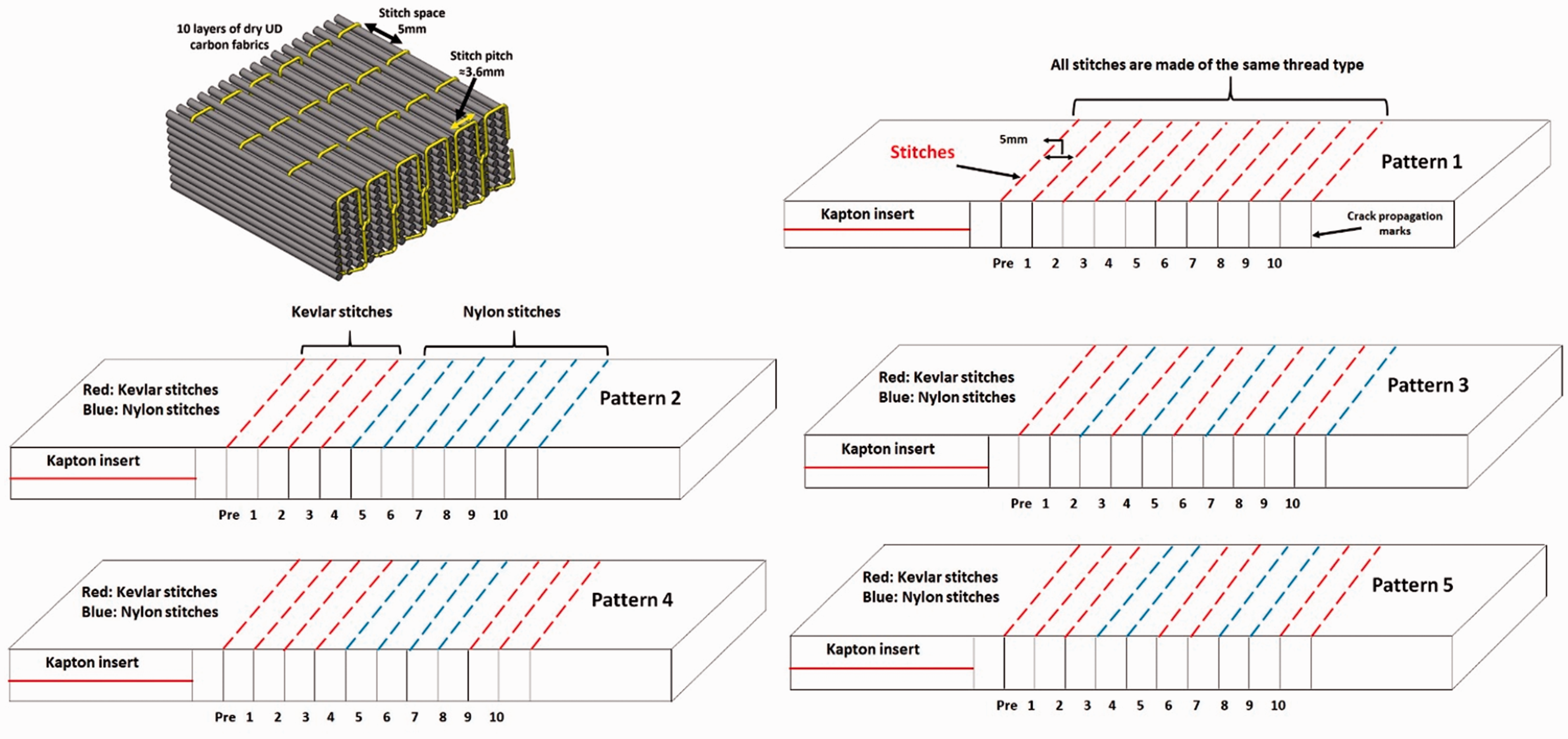
Lock stitch with the stitch pitch, the stitch space, and the five patterns of stitching used in this study. Two laminates of pattern 1 were manufactured, one stitched with Kevlar and the other stitched with nylon.
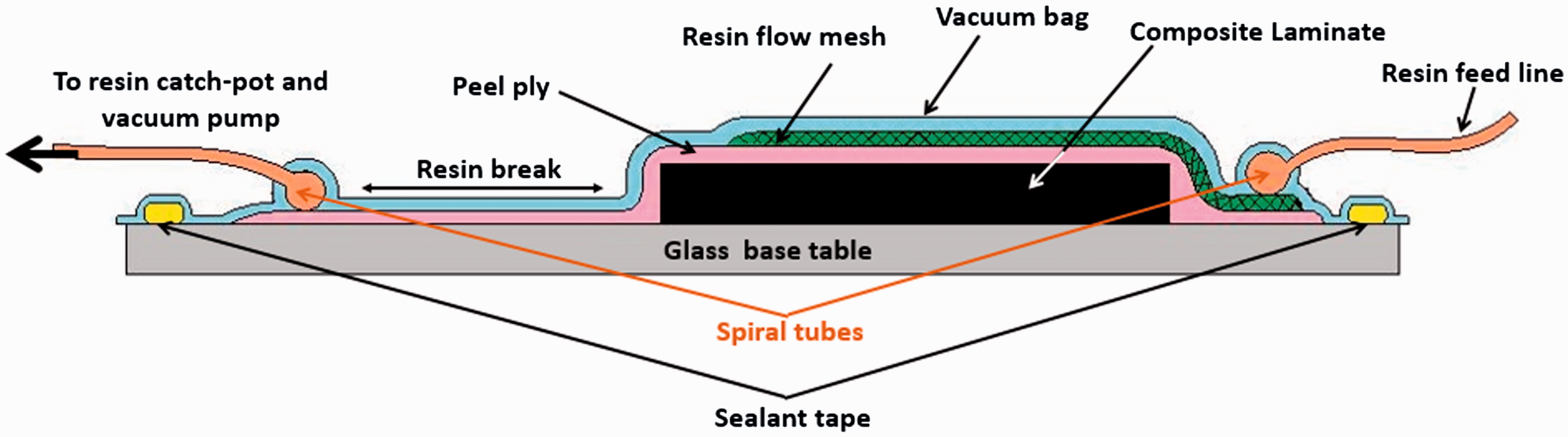
Schematic illustration of the resin infusion setup “side view.”
Mode I specimen preparation
Mode I specimens were cut to dimensions shown in Figure 3, in accordance with ASTM standard D5528 (width b = 25 mm, length L = 150 mm, average thickness t = 4 mm, and initial crack length ao=57 mm). 20 The UD fibers were oriented with the length direction (L). The Kapton insert length (63 mm), the length of each specimen, the width and thickness at three locations along the specimen’s length were measured using SENATOR-SEN-1–1250K digital caliper with 0.01 mm resolution.
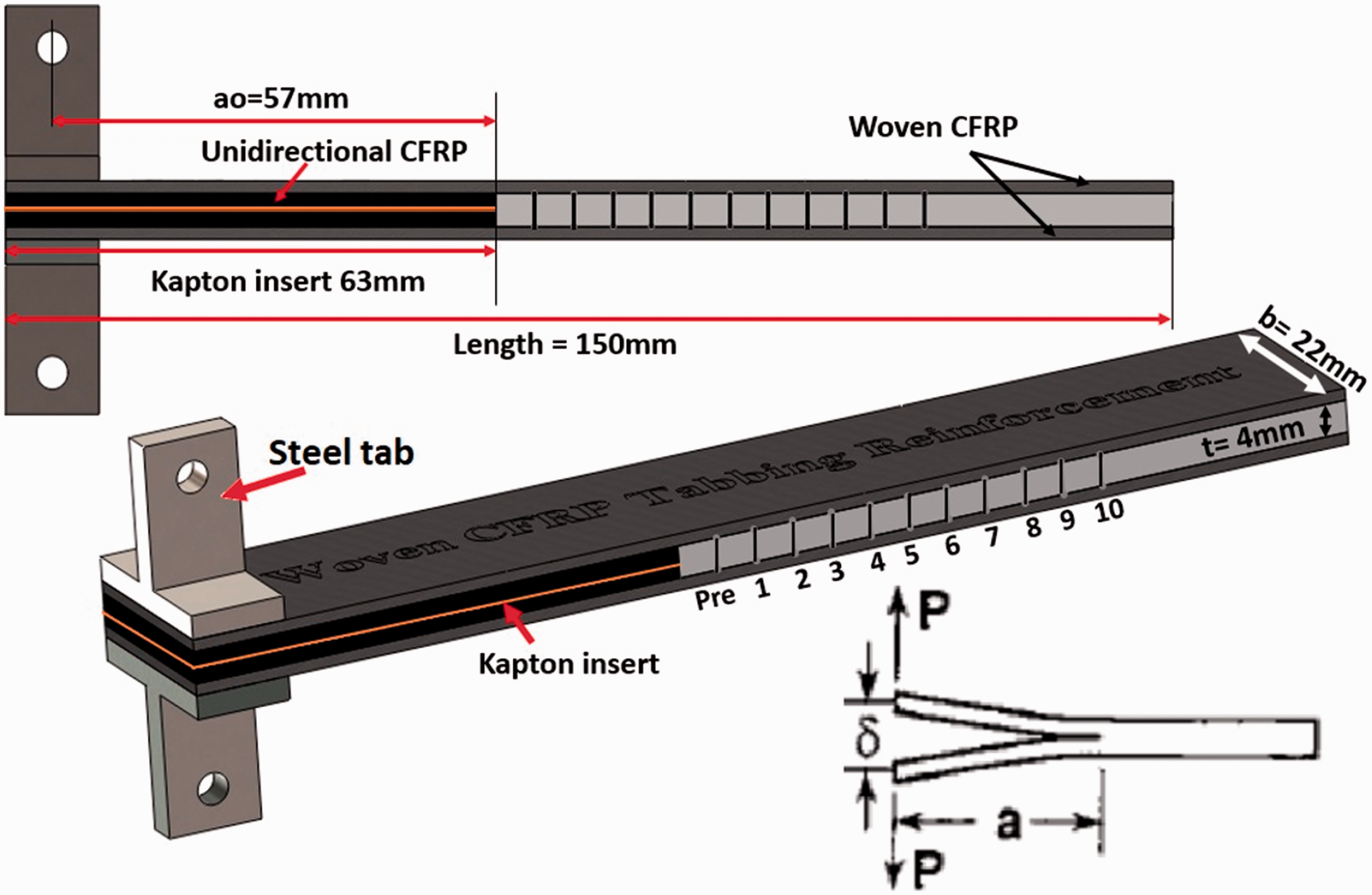
Side view and 3D view of the DCB – Mode I test specimen showing the dimensions, the tabbing reinforcement, the steel tabs and the crack initiation and propagation marks.DCB: double cantilever beam.
To avoid specimen’s arms failure during Mode I test due to excessive bending load, tabbing reinforcements were secondarily bonded to the stitched specimens. The tabbing reinforcement laminates were made of four woven carbon fiber layers and manufactured using the VARTM setup shown in Figure 2. The tabbing reinforcements were attached to the upper and lower surfaces of the specimen using the HYSOL/glass bead adhesive mixture described in Abdelal and Donaldson 19 after grinding and cleaning both surfaces of the specimen.
Steel T-tabs were attached to the upper and lower surfaces of Mode I specimens using the HYSOL adhesive mixture as described in Abdelal and Aljarrah. 21 The edges of each specimen were painted with white paint just ahead of the insert end as shown in Figure 3 to facilitate monitoring the crack initiation and propagation through the travelling microscope during the Mode I test. The painted edges were marked at 5 mm divisions from the end of the insert to a total length of 55 mm to ease monitoring the crack propagation during the Mode I test. The first mark line at 5 mm from the end of the insert was used to precrack the sample, whereas the remaining 10 divisions (50 mm) were used to monitor the crack in the crack propagation stage. Note the stitches were aligned with the crack propagation marks.
Electromagnetic interference shielding effectiveness measurements
The specimens in this project were tested according to the setup described in literature3,15,17,22–24 which is a viable setup for electromagnetic interference shielding effectiveness (EMI-SE) measurements in the high frequency range (8–12 GHz). The setup consisted of E5071CENA series 300 kHz–20 GHz Network Analyzer connected to WR90 rectangular waveguide (SIVERS lab – Philips PM-7328-X) via coaxial cables as shown in Figure 4. The setup was calibrated using Agilent N4433A (300 kHz–20 GHz) electronic calibration module. Specimens from each composite type were cut to fit in the waveguide sample holder, and then attached to the network analyzer via the coaxial cables as shown in Figure 4. The scattering parameters (S-parameters) (S11, S12, S21, S22) were recorded for each sample in the X-band frequency range (8.0–12.0 GHz). At least five specimens from each composite laminate were tested in the orientation as shown in Figure 4. The UD fibers were aligned parallel to the long side of the waveguide and the stitches were perpendicular to the waveguide long side. This test was conducted to investigate the effect of stitching on the EMI-SE of the composites. Much larger specimens were tested in lower frequency range (0.75–1.1 GHz) using the setup described inMicheli et al. 25
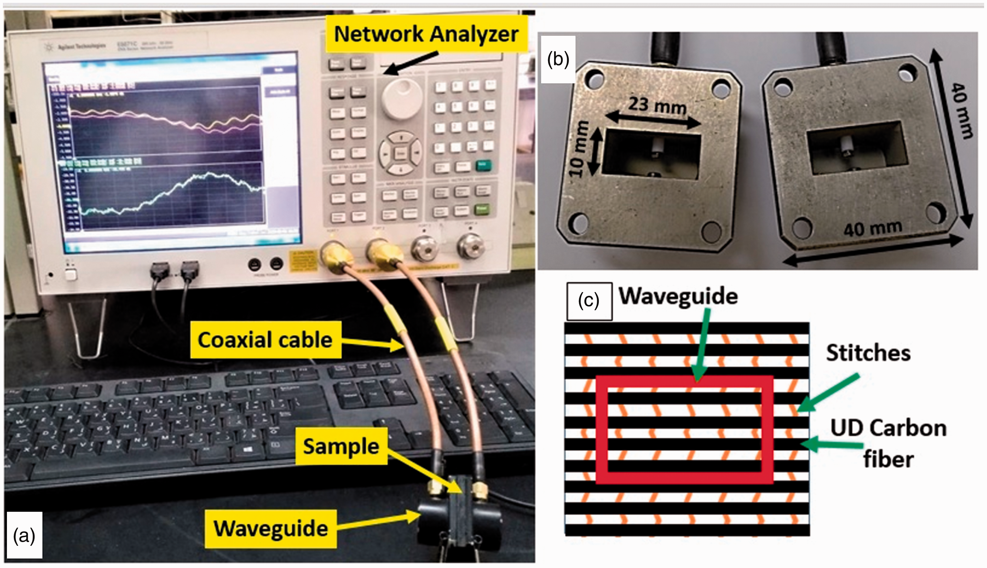
(a) Electromagnetic shielding effectiveness (EMI-SE) measurement setup (b) The dimensions of the rectangular waveguide (c) Schematic illustration showing the direction of the carbon fibers and the stitches with respect to the waveguide; the UD-CFs are parallel to the long side of the waveguide (black: UD carbon fibers, orange: stitches). UD: unidirectional; CF: carbon fiber.
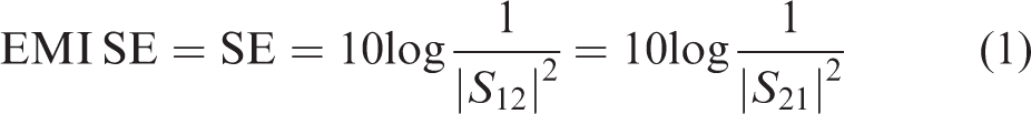
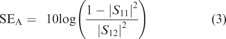
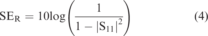
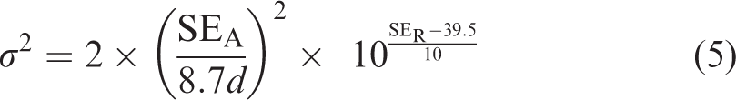
Using the S-parameters, the total EMI SE, the absorption loss (SEA), the reflection loss (SER) and the electrical conductivity of each sample at each frequency were calculated using equations (1) to (5)15,17,22,23,26

Mode I – Double cantilever beam tests
The tensile properties (maximum load to fracture, maximum elongation to fracture and fracture energy) of the stitching threads (Kevlar and nylon) were determined following the procedure described in Abdelal and Donaldson. 19 Double cantilever beam (DCB) – Mode I tests were carried out on stitched and unstitched specimens following the ASTM D5528 standard. The test setup consisted of computer-controlled screw-driven testing machine (jinan-WDW20) equipped with 2 KN load cell. The tests were conducted in displacement-controlled mode at 2 mm/min crosshead speed, following the same procedure explained in Abdelal and Donaldson 19 and Abdelal and Aljarrah. 21 Seven specimens from each composite laminate (representing the unstitched composite and the five composite patterns) were tested to calculate Mode I interlaminar fracture toughness GIC at multiple crack lengths, a. The testing process was conducted in two stages; precracking and crack propagation according to the process explained in Abdelal and Donaldson 19 and Abdelal and Aljarrah. 21
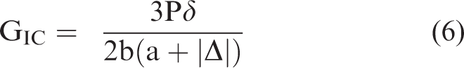
The interlaminar fracture toughness (energy release rate) of Mode I fracture (GIC) was calculated using the modified beam theory with the correction factor Δ (MBT-Δ) using equation (6) shown below
20
Fractographic analysis
The fractographic analysis was conducted on during the Mode I test using the travelling LED-illuminated digital microscope. Images were taken during crack initiation and propagation to assist in interpretation of the mechanical behavior.
Results and discussion
Mode I interlaminar fracture toughness of unstitched and hybrid composites
Figure 5 shows Mode I interlaminar fracture toughness, GIC, versus crack length, a, curves of samples from unstitched and hybrid stitching composites. The GIC is calculated at each crack length from (a1 to a10) using the MBT-Δ method, where GIC at the crack length a1 is considered as the crack initiation interlaminar fracture toughness (GIC-initiation) and GIC at the crack length a10 is considered as the final interlaminar fracture toughness (GIC-final). Several observations can be made from this figure: GIC of the unstitched composite increases slightly at the short crack stage then stabilizes at longer crack lengths. In addition, composite stitched with Kevlar (pattern 1) shows the highest crack initiation GIC values, but do not increase significantly during the crack propagation. However, composites stitched with nylon (pattern 1) shows lower initiation GIC values which are similar to the unstitched composite, but the GIC increases tremendously with crack propagation, until it reaches its maximum value at the final crack length (a10). It was hoped that a hybrid approach would take advantage of this behavior, using a Kevlar stitch for shorter crack lengths, and a nylon at longer crack lengths. The results from the four hybrid-stitched composites approaches are also shown in Figure 5. The four hybrid designs show slightly higher crack initiation fracture toughness (GIC-initiation) values compared to the unstitched composites, and with further crack growth, GIC increases significantly in all patterns. It is worth mentioning that GIC-initiation of the four-hybrid stitching patterns is higher than the unstitched and stitched with nylon composites and lower than stitched with Kevlar composite, whereas GIC-maximum of all of the four-hybrid stitching patterns is higher than the unstitched and stitched with Kevlar composites, although lower than stitched with nylon composite. This complies with the initial goal of this study to manufacture hybrid stitching composites with combined properties between Kevlar and nylon stitched composites. When comparing the behavior of the four-hybrid-stitched composites, it is noticed that the fracture toughness values slightly increase from crack initiation a1 up to crack length a5 or a6, then exhibit significant increase beyond that. In addition, patterns 2 and 4 show the smoothest transition in the fracture toughness increase from crack initiation to complete delamination, whereas patterns 3 and 5 show an S-shaped fracture toughness behavior.
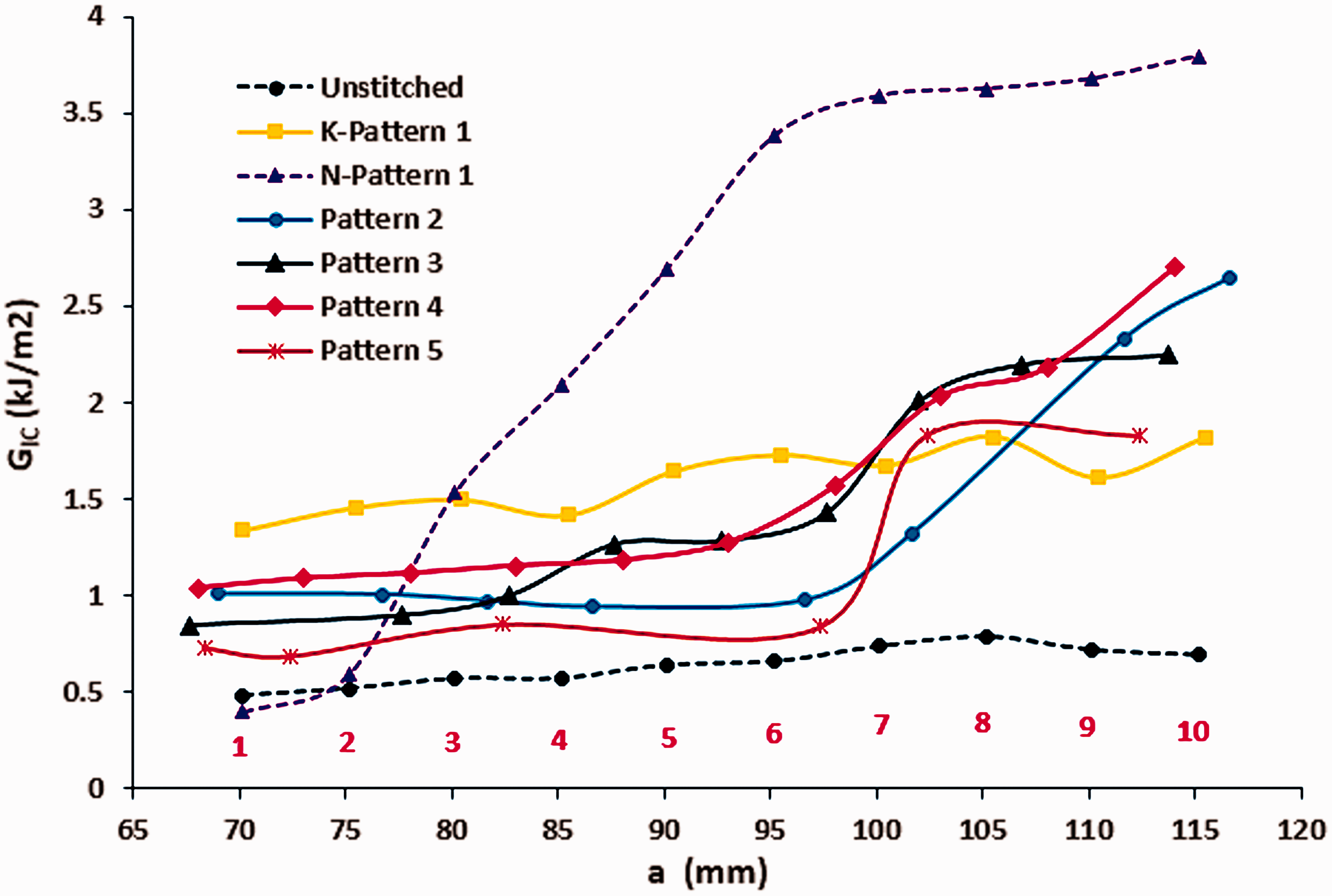
R-curves for representative samples of unstitched, stitched with Kevlar, stitched with nylon and hybrid-stitched composites of different patterns (K: Kevlar and N: nylon).
The behavior of the nylon-stitched composite and Kevlar-stitched composite from pattern 1 were explained in detail in Abdelal and Donaldson. 19 The behavior of the four-hybrid stitching composites can be explained as follows: the initiation and maximum fracture toughness values (GIC-initiation and GIC-maximum) of the hybrid stitching composites come from the fact that these composites contain both nylon and Kevlar threads that are stitched in different patterns, hence the resulting fracture toughness results are compromised between the behavior of stitching by each type of thread individually.
The numerical values for all specimens tested are reduced and shown in Figure 6. It shows that the initiation values for all four hybrid patterns are somehow similar, whether two, three, or four rows of Kevlar stitches exist at the crack initiation zone. The only other obvious difference between the four hybrid approaches is the higher final values in Pattern 2, which is not surprising since it has the most nylon stitches in the latter half of the specimen. Beyond that, the numerical values seem to be close to falling within the experimental scatter (patterns 3, 4, and 5).
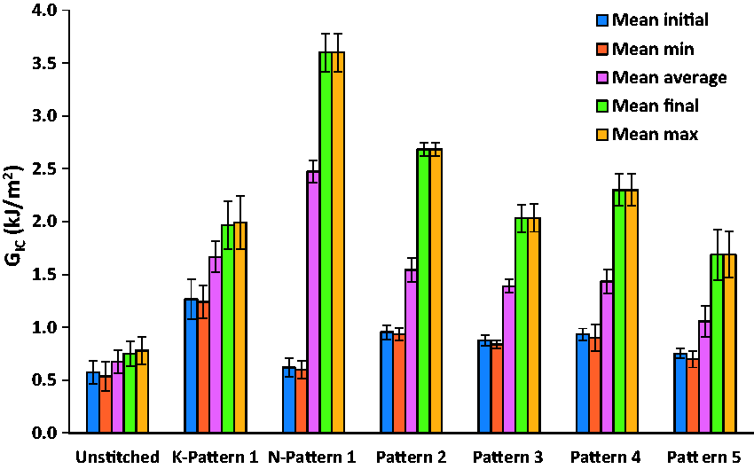
Summary of the Mode I-DCB results: The mean values of the initiation, minimum, maximum, final and average interlaminar fracture toughness (GIC-initiation, GIC-minimum, GIC-final, GIC-maximum and GIC-average) with the standard deviation error bars. DCB: double cantilever beam.
From Figure 5, pattern 4 shows the highest and smoothest increase in the fracture toughness between crack initiation and complete delamination among the four hybrid patterns because it contains alternating sets of Kevlar and nylon stitches that support each other, i.e. the Kevlar offers the high values in the fracture toughness, whereas the nylon offers the continuity of the enhancement in the fracture toughness due to the tremendous elongation preventing the sample’s arms from separating. The first set of three rows of Kevlar stitches provide high GIC-initiation value due to the brittle nature of Kevlar stitches, whereas the middle set of the four rows of nylon stitches provide higher GIC values in a smooth transition due to the tremendous elongation in the nylon stitches before breaking. The crack propagates toward the last set of three rows of Kevlar stitches which enhance the delamination resistance provided by the elongated nylon stitches without any breaking in the nylon stitches or even any separation between the upper and lower arms of the specimen providing the smooth yet highest GIC values until complete delamination. Pattern 2 shows similar behavior to pattern 4 but with slightly lower GIC values between crack lengths a4 to a9 because there is a transition from Kevlar-stitched zone to completely nylon-stitched zone without any supporting Kevlar stitches at the end to enhance the delamination resistance provided by the elongated nylon stitches as seen in pattern 4. Pattern 3 shows ups and downs (increase then decrease) in the GIC values due to alternating stitching of the brittle Kevlar and ductile nylon. Finally, pattern 5 exhibits the least favorable behavior among the four hybrid patterns due to the jumps that the crack experiences when propagating from the Kevlar-stitched zone to the nylon-stitched zone. The majority of pattern 5 specimens exhibit crack jumps from point 2 to point 5 and from point 6 to point 9 where nylon stitches exist. This can be explained by the fact that when the crack propagates in the Kevlar-stitched zone it encounters large resistance to delamination; however, the entire row of stitches broke suddenly in a brittle manner, causing the crack to suddenly jump to the nylon-stitched zone where resistance to delamination is lower than Kevlar, causing a jump around that zone. This behavior will be explained in more detail in the fractographic section.
As mentioned before, Figure 6 summarizes the Mode I test results in this study. For each composite type, the mean value of all tested specimens’ initial, minimum, maximum, final and average values of GIC are calculated and plotted as a bar with a standard deviation error bar. The figure shows that the crack initiation fracture toughness (GIC-initial) increases significantly when stitching with Kevlar-pattern1, whereas it shows very slight increase when stitching with nylon-pattern1. However, the hybrid stitching composites from patterns 2, 3, 4 and 5 show higher GIC-initial values (0.95, 0.84, 0.93 and 0.75) kJ/m2 compared to the unstitched (0.57 kJ/m2) and stitched with nylon-pattern 1 (0.6 kJ/m2) composites but slightly lower than composite stitched with Kevlar-pattern 1 (1.27 kJ/m2). Moreover, Figure 6 shows that the maximum fracture toughness GIC-max increases by 156% and 360% when stitching with Kevlar and nylon of pattern 1 compared to the unstitched composite, respectively. However, hybrid stitching composites of patterns 2, 3, 4 and 5 show 244%, 160%, 195% and 117% increase, respectively, compared to the unstitched. It is obvious that hybrid stitching composites from patterns 2, 3 and 4 show intermediate GIC-max values between those stitched with Kevlar and nylon from pattern 1 and same trend applies to GIC-avg.
Fractographic analysis
To help interpret the mechanical crack growth behavior, the crack initiation and propagation were monitored and images were taken during Mode I tests using a digital LED travelling microscope. Figure 7 shows images of six samples during the Mode I testing, one stitched with Kevlar-pattern 1, one stitched with nylon-pattern 1 and the other four are hybrid specimens from patterns 2, 3, 4 and 5. In the Kevlar-pattern 1 sample, it is clear that the crack propagated between the stitching rows in a sudden manner causing separation between the two arms of the sample without significant elongation in the Kevlar threads due to the more brittle nature of Kevlar when compared to nylon. On the contrary, the nylon-pattern 1 crack propagated, while the two arms of the sample remain attached via the significantly elongated nylon threads. Hybrid pattern 2 and 4 samples exhibit high crack initiation fracture toughness due to the first four rows of high strength and brittle Kevlar stitches which resist delamination initiation. Crack propagation resistance is maintained and enhanced during the crack propagation stage where a significant fiber bridging is obvious and the upper and lower arms of the sample stay attached together by the existence of the remaining rows of significantly stretched nylon. Hybrid pattern 3 and 5 samples show the alternating Kevlar/nylon stitches. While the crack propagating in the Kevlar-stitched zone causing the threads to break in a brittle manner, it propagates through the nylon-stitched zone keeping the upper and lower arms of the sample attached. It is clear in both patterns that the Kevlar threads behind the elongated nylon threads are broken and the crack is propagating which explains the rises, falls, and jumps in the R-curves shown earlier.

Side view images of stitched samples from all patterns during Mode I test.
EMI-SE results
The SE was calculated for each tested specimen in the 8–12 GHz frequency range with frequency increment of 0.02 GHz using equation (1). Figure 8 shows EMI SE versus frequency curves of representative specimens of unstitched and stitched composites from different patterns. Stitched composites from all patterns exhibit significant increase in the SE compared to the unstitched composite in the investigated frequency range. The average SE values were calculated for all tested specimens over the 8–12 GHz frequency range and included in Table 1. Figure 8 and Table 1 show that average SE increases from 22.84 dB for unstitched composite to around 40.6 dB for composite stitched with Kevlar-pattern 1 and around 52.17 dB for composite stitched with nylon-pattern 1 corresponding to and 78% and 128% increase in the SE compared to the unstitched, respectively. In addition, the four-hybrid stitching composites exhibit similar SE-frequency curves with an average SE of 32.75 dB corresponding to around 44% increase compared to the unstitched composite. Moreover, it is believed that the SE of unstitched composite is almost independent of the frequency. However, stitched composites regardless the pattern and stitching thread used exhibit slightly continuous increase in the SE with increasing frequency.
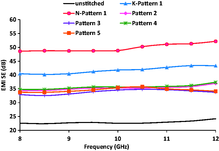
Electromagnetic shielding effectiveness (EMI-SE) of unstitched and stitched composites from all patterns (K: Kevlar and N: nylon).
Average values of: electromagnetic shielding effectiveness (EMI-SE), absorption loss (SEA), reflection loss (SER), conductivity and thickness.
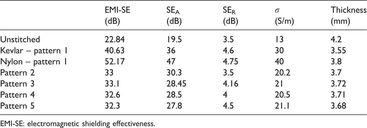
EMI-SE: electromagnetic shielding effectiveness.
Table 1 shows that the absorption loss (SEA) for each type of composite is higher than the reflection loss (SER) implying that the dominant effect of shielding in these composites is absorption. It is clear that the absorption loss increases from 19.5 dB for the unstitched composite to 36 dB for composite stitched with Kevlar, 47 dB for composite stitched with nylon and around 28.8 for the hybrid composites. This is because the electromagnetic wave’s wavelength decreases at high frequency ranges (X-band) and becomes closer to the fiber size; therefore, it is easier to be absorbed than reflected by the composite.26–28 Moreover, Table 1 shows that the average conductivity increases from 13 S/m for the unstitched composite to 30 S/m for the composite stitched with Kevlar and 40 S/m for the composite stitched with nylon. However, the four hybrid-stitched composites show similar conductivity values with an average 20.7 S/m. It is clear that the composite stitched with nylon has the highest conductivity with 207.7% increase compared to the unstitched composite.
It is believed that the aforementioned behavior can be interpreted as follows: it is well known in the literature3,15,29–31 that UD carbon fiber composite has higher conductivity along the fiber direction compared to the transverse and through-the-thickness directions which are saturated with the dielectric polymer matrix. It is also known that when using rectangular waveguide with TE mode, the electromagnetic field is linearly polarized in the waveguide. Thus, if the carbon fibers are aligned with the electric field polarization direction, they behave as good conductors (carbon fibers are aligned with the short side of the waveguide), whereas they behave as dielectric polymer with a finite conductivity in the transverse direction (carbon fibers are aligned with the long side of the waveguide as shown in Figure 4(c)). Therefore, when stitching the UD-CFs together, the stitching threads compress the UD fibers in the transverse and through-the-thickness directions creating conductive networks and channels for the electric field and electromagnetic waves to flow. Thus, stitched composites exhibit improved SE and conductivity compared to the unstitched composite regardless the type of stitching thread because conductive networks are created in the transverse direction. However, the higher SE values of the composite stitched with nylon compared to other types can be attributed to two factors: first, the higher conductivity of the composite stitched with nylon which ease the flow of the electrical current and electromagnetic waves in the composite. Second, as can be seen in the prior work,
19
nylon has a smaller diameter compared to Kevlar and it consists of one single thread that does not cause significant damage to the fabric texture in the transverse direction compared to the multi filament Kevlar with larger diameter which causes noticeable damage to the CF tows in the transverse direction that results in separation between the tows and formation of dielectric resin pockets. Finally, composite stitched with nylon has larger thickness (3.8 mm) compared to those stitched with Kevlar (3.5 mm) and it is clear from equation (5) and the relation SEA = 8.7d
Conclusions
This research experimentally investigated the effect of hybrid stitching on the Mode I interlaminar fracture toughness and the EMI-SE of UD carbon/epoxy composite laminates. Unstitched and hybrid-stitched laminates with Kevlar and nylon were manufactured using VARTM. Specimens from all composite types were tested using DCB delamination crack growth test setup and rectangular waveguide.
Mode I test results showed that stitched composites had higher initiation and propagation interlaminar fracture toughness compared to the unstitched composites. Samples stitched with Kevlar exhibited higher initial critical energy release rate, whereas samples stitched with nylon showed better overall fracture toughness. The hybrid-stitched samples exhibited intermediate crack initiation and propagation fracture toughness values compared to those stitched with Kevlar and nylon alone.
Electromagnetic SE results showed that stitched composites exhibited higher SE values compared to the unstitched composites. Composite stitched with nylon had the highest SE values, whereas the four hybrid-stitched composites showed similar effectiveness behavior.
Footnotes
Acknowledgements
The authors would like to thank Royal Jordanian Airline for providing the HYSOL adhesive. The authors also thank Dr. Nihad Dib from the department of electrical engineering at Jordan University of Science and Technology for the valuable discussions in the field of electromagnetics.
Declaration of conflicting interests
The author(s) declared no potential conflicts of interest with respect to the research, authorship, and/or publication of this article.
Funding
The author(s) disclosed receipt of the following financial support for the research, authorship, and/or publication of this article: This work was financially supported by the Deanship of Research – Jordan University of Science and Technology, Irbid – Jordan, research grants with the numbers (184/2015) and (345/2016).