
Abstract
Carbon fiber reinforced plastics have been widely applied in aircraft structures, which require more rapidly repairing process when carbon fiber reinforced plastics structures are damaged. A novel method of self-resistive electrical heating to rapidly repair carbon fiber reinforced plastics parts was investigated, which utilizes the electrical current passing through the carbon fiber to generate heat and directly cure the whole carbon fiber reinforced plastics patches. A portable self-resistive electrical repairer with automatic temperature control unit was developed. Repair experiments of self-resistive electrical and the electrical blanket heating were conducted, in which the heating temperature distribution field was observed by the thermal infrared imager. The degree of cure of different samples was characterized, and the cross-section morphology and void content of different samples were assessed. Flexural and inter-laminar shear tests were carried out. The experiment results showed that the flexural and interlaminar shear strength recovery ratio of self-resistive electrical repaired samples attained to 85.48% and 65.89%, which was the same or even slightly higher level as the blanket repairing process, but only cost 62% repairing period and 58% repairing energy of the later one. Finally, from the experimental results, the heat transfer behavior of different processes was analyzed.
Keywords
Introduction
With the continuous development of aviation manufacturing industry, carbon fiber reinforced plastics (CFRPs) have been widely used in many load-bearing structures of aircraft due to their high specific strength and modulus, high temperature, corrosion and fatigue resistance.1–5 Because of the existence of lightning strike, birds impact, bullets hit and hailstone hit, etc., the in-service aircraft is inevitably suffering from various structural damages such as localized cracks, scorches, delamination, and holes.6–9 These damages significantly reduce the static and dynamic load performance of CFRPs structures, and may directly threaten the flight safety of aircraft. For civil aircraft, the grounding caused by depot maintenance would bring a huge economic loss. 10 Similarly for the military planes, the inability to rapidly repair on the field would result in the loss of air supremacy on the battlefield. 11 Therefore, it is significant to develop rapid field repairing or maintenance technologies of the damaged CFRPs parts in aircraft service process, which requires immediate curing process to restore the structural strength and stiffness as fast as possible.12–14
The traditional field maintenance methods to cure CFRPs parts mainly include heat blankets heating, infrared radiation etc., among which the low heating/curing rates and non-uniform temperature distribution field limit the efficiency and quality of repairing process.15–16 These conventional heating methods generally follow the principle of heat transferring from the external heat source. Resulting from the poor thermal conductivity along the thickness of CFRPs patches, a temperature gradient ineluctably appears in the above repairing process, and a follow-up large thermal stress inside the repair area would significantly destroy the curing quality.17–19 Besides, the in-plane temperature of electrical blanket is not uniform because of the uneven distribution of wire resistance. For optimizing the temperature distribution, a long repair cycle with multiple insulation platform is applied in these heating processes, and the curing cycle is even up to 4 h in some severe case. 20 Some novel rapid curing techniques have been proposed and applied in field repair processes, such as ultraviolet (UV) light curing, microwave curing and electron beam curing.21–23 These technologies generally require complex equipment, and some of them only fit for specific material systems. For example, only photosensitive resin can be cured by UV-light, and the microwave curing can only penetrate and heat unidirectional CFRPs laminates.24–26 In addition, the leaks or radiation generated by the high power electromagnetic wave or electron beam are harmful to the human body, which makes these methods hard to become widely available in the field of maintenance applications. 27
In order to realize the goal of higher quality, shorter repair cycle and lower cost, a novel self-resistive electrical (SRE) heating method to rapidly repair CFRPs is investigated in this paper. By mounting the electrodes at both ends of the prepreg patches, the electrical current passes through the carbon fiber to produce the joule heat, and eventually the CFRPs patches are cured by the joule heat generated by themselves. In the past literature, SRE heating has been used in the processes of CFRPs curing28–35 and composites joints bonding.36,37 The results showed that SRE heating not only significantly reduced energy consumption, and shortened the curing cycle, but also achieved a preferable curing quality. Besides, in the CFRPs structures repair area, Mahdi et al.38,39 introduced SRE repairing method used in composite scarf repair process, in which the SRE repaired scarf had the higher tensile strength. However, during the SRE repairing process, the influence mechanism of the electrical current to other performance including flexural and interlayer shear strength of repaired structures is yet to be revealed, and the mechanical performance recovery rate after SRE repairing requires further characterized.
This paper focuses on the method of SRE repairing method for CFRPs parts. A portable SRE repairing equipment with automatic temperature control unit was developed. Repair experiments of different process including SRE and the electrical blanket were carried out, in which the heating temperature distribution field was monitored by the thermal infrared imager. The degree of cure of different samples was characterized and analyzed. Flexural and inter-laminar shear tests were severally conducted, and the failure mechanism was discussed. The main objective of this work is to perform the novel SRE repairing process by using the portable equipment, and to compare the temperature distribution, energy consumption and mechanical performance recovery ratio of it to the conventional blanket repairing process.
Materials and methods
Materials
Carbon/epoxy unidirectional prepreg UIN/10000/T800 (China Weihai Guangwei Composite Co., Ltd) was employed in this study as the body laminates to be repaired and also the patches, which have the resin content of 30% and is typically applied in several industries including aerospace. The body laminates were vacuum bagged and cured in the autoclave following the recommended cure cycle of the ramp at 1°C/min to 120°C, and hold for 90 min, and then ramp at 2°C/min to room temperature. The applied air pressure inside the autoclave was set to 0.7 MPa. When the temperature dropped to 60°C, the autoclave pressure was released. The red copper strip of T2 (Hengxu Hardware Co., Ltd) with the purity of 99.7% was adopted as the electrode in SRE repairing process. Other materials used in the experiment were purchased from the supplier Airtech Co., Ltd.
Facilities
A portable SRE repairing equipment for field maintenance was developed by the authors. As shown in Figure 1, the requisite systems for CFRPs repairing including the human-machine interaction screen, temperature control unit and SRE heating power are all integrated in the main case. The vacuum pump, grinder with soft shafts and the auxiliary materials are loaded in the assistant case. On the operation panel of the main case, two channels of strong current output interfaces are on the upper right corner, which can independently offer the maximum current and power of 300 A and 4.5 kW, respectively. The signal of 10 channels of K type thermocouple sensors can display on the interactive touch screen, and generate the temperature curves in real time. The user can choose any signal channel of temperature sensors for the PID control of SRE heating power. The electrical current and voltage values can also be displayed and recorded during the repairing process.
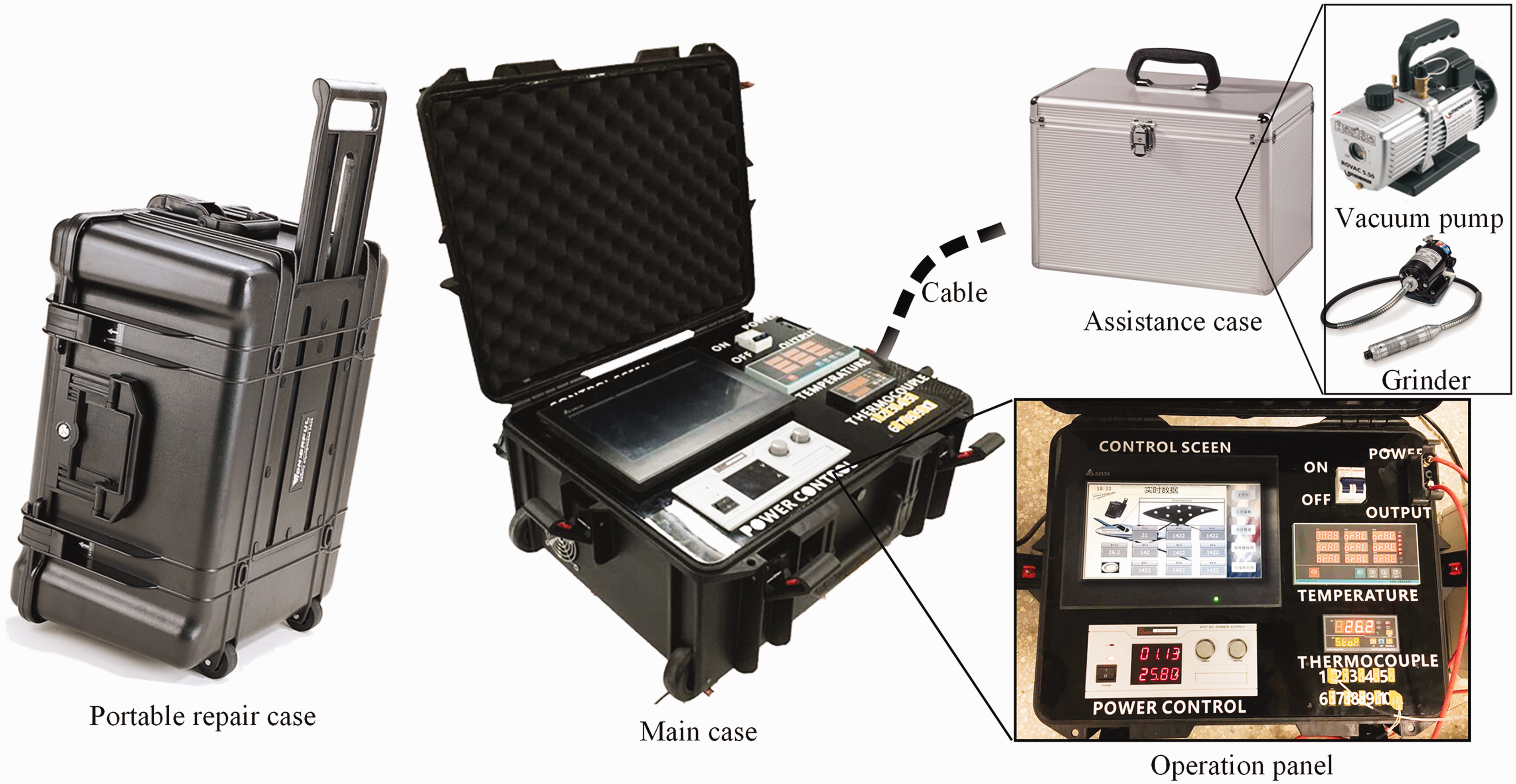
The composition diagram of the self-developed SRE repairing systems. SRE: self-resistive electrical.
Additionally, the autoclave with the diameter of 1.5 mm, length of 2 mm (Jiangsu Taixing Co., Ltd) was used to cure the body CFRPs laminates. An industrial-grade heat blanket with the size of 500 × 500 mm (Tianjing Zhouyu Co., Ltd) was applied for the comparative repairing experiment, which has the maximum heating rate of 2°C/min. The energy consumption of the SRE and blanket repairing process was recorded by a power meter of PF9811 (Everfine Co., LTD) connected between the heating source and the power supply.
Preparation for CFRPs body laminates and unrepaired samples
For simulating the actual damaged CFRPs parts, three pieces of body laminates with the stacking sequence of [0°/90°] were firstly manufactured in the autoclave followed by the recommended curing cycle, and they had the dimensions of 200 × 100 × 2.5 mm. Then for acquiring the damaged part, two of the body laminates were milled into a subsidence with the dimension of 100 × 100 × 1 mm by the soft shaft grinder, as shown in Figure 2(a). The laminates A and B were for SRE and blanket repairing, respectively, and the untreated laminate C was for the undamaged structure.
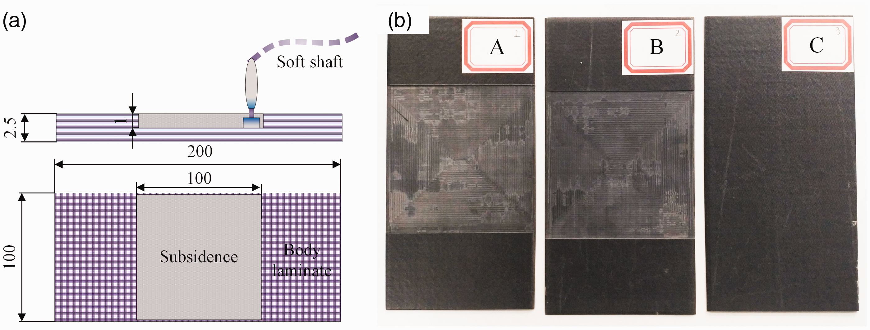
(a) Schematic diagram of the treatment of damaged area. (b) The polishing treated laminate A and B, untreated laminate C.
Blanket and SRE repairing arrangements
In this paper, blanket and SRE heating methods were utilized to cure the patches placed on the milled subsidence. As illustrated in Figure 3(a) and (c), the stacked CFRPs patches with the dimension of 100 × 120 × 1.1 mm followed the stacking sequence of [0°/90°] were implanted into the subsidence, and the whole setup was cured on an aluminum tool, respectively, by the electrical blanket and SRE repairing. For blanket repairing process, a 300 × 300×2 mm metallic caul plate was added between the heating blanket and composite material for temperature uniformity. In Figure 3(c), for the SRE process, the electrodes were loaded in both the ends of the patches, and each layer of prepreg contacted a thin copper strip. The temperature sensors were placed on the edge of the patches to measure the real-time temperature signal, which was used as the feedback of the PID controller. Both the repairing process was followed by the recommended layout method of the vacuum auxiliary materials as shown in Figure 3(e).
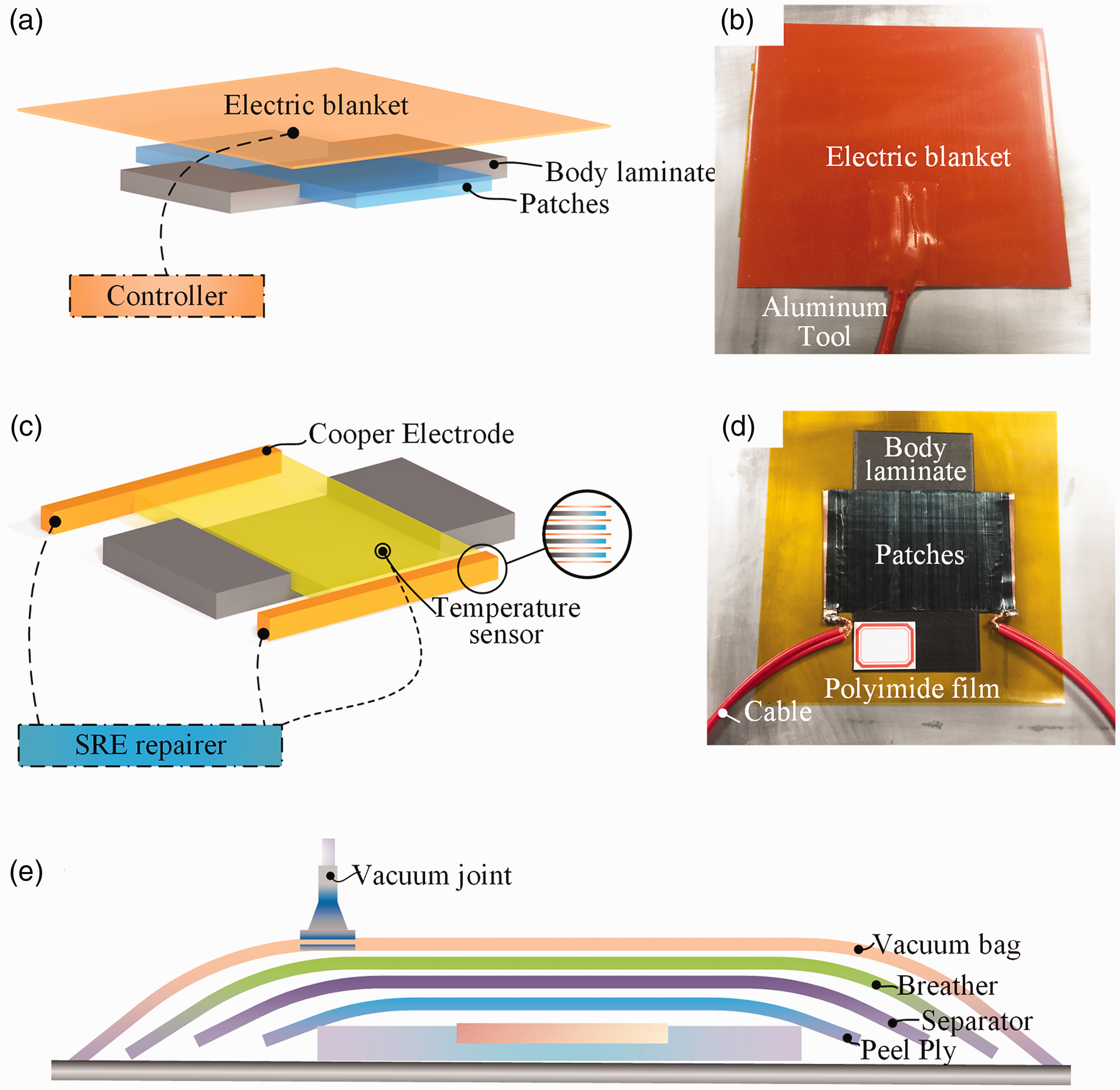
Schematic diagrams of the (a) electrical blanket and (c) SRE repairing process arrangement, photos of (b) blanket and (d) SRE repairing process, (e) the layout schematic of the auxiliary material of all repairing process. SRE: self-resistive electrical.
Performance testing and characterization
Degree of cure
The degree of cure (α) of the samples was characterized by the DSC 204F1 (NETZSCH Inc.). Samples with weight fluctuated at 10 mg were sealed in the aluminium pan, and heated from 25°C to 200°C at a heating rate of 20°C/min in a nitrogen atmosphere. α was calculated from equation (1).

Cross-section morphology and void content measurement
The cross-section of different sample was observed by the optical microscopy (BMM-50E, BIMU, China). The void content was characterized according to 18 non-overlapping images captured from three different sections.
Flexural and interlaminar shear performance tests
Repaired and undamaged samples were all cut into flexural and interlayer shear test sizes according to the standard of ASTM D7264/D7264M-07 and D2344/D2344M-00 for flexural and interlaminar shear strength (ILSS) of polymer matrix composite material. All the tests were conducted on the universal testing machine of WDW e200d with a 50 kN load cell. Flexural strength was measured by three-point bending with the span-to-thickness ratio of 32:1, and crosshead movement speed of 1.0 mm/min. ILSS was measured by short-beam three-point bending when the span-to-thickness ratio was of 4:1, and crosshead movement speed was 1.0 mm/min.
Results and discussion
The heating process and temperature distribution field assessment
The heat transfer mechanism during SRE and blanket heating process is illustrated in Figure 4(a) and (b).The heat sources and heat transfer paths are represented by the red areas and black arrows. In the traditional electrical blanket heating process, heat was firstly transferred along the thickness direction of CFRPs patches and also the body laminates from the blanket towards the bottom. Meanwhile, heat radiation occurred everywhere in the whole blanket. These heat transfer behaviors resulted in a large number of energy consumption process because of the inevitable heat dissipation, and a great temperature gradient was formed along the thickness direction of patches. Most seriously for field maintenance, because of the poor heat conductivity along the thickness direction of CFRPs laminate, the heating rate of blanket repairing process might be unsolvable low. However, for the SRE process, the only heat source was the CFRPs patches themselves, and every fiber being conducted by the current achieved an absolute even temperature field along the thickness direction. Undamaged structures were merely heated except the boundaries tightly contacted with the patches. Therefore, except the thermal dissipation of small area, almost all the energy was used to heat the patches, that is to say an energy-efficient repair process was achieved by the SRE heating. The above analysis was also verified by the results of the power meters. The SRE repairing only consumed 1.74 kW·h for the whole curing process, which was only about 58% of that of the blanket repairing process.
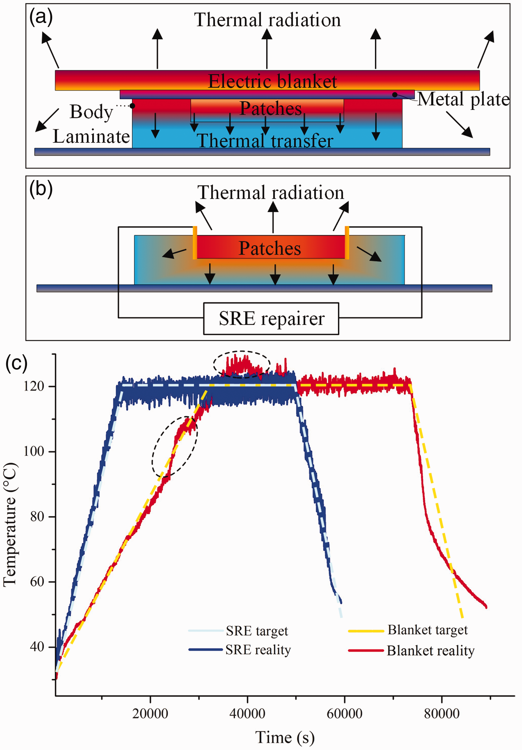
Heating process setting and the actual heating curves of blanket and SRE repairing.
Temperature responsive behaviors of SRE and blanket heating process were compared. The temperature in the repair area was measured with K-type thermocouples. As shown in Figure 4(c), considering the heating rate limitation of blanket heating, the heating process was set following the heating rate of 1°C/min to 120°C, and then a dwell of 90 min. A heating rate of 3°C/min and same dwell of 90 min was applied in the SRE heating process. For both repairing processes, a temperature control lag of ±5°C was achieved. Due to the intense heat dissipation at high temperature stage for blanket repairing process, there were some fluctuations during the initial dwell stage. At cooling phase, both repairing process achieved fast cooling rate of 3°C/min. This was owing to that there was no external heat source surrounded and the cold air directly contacted repairing system to exchange the heat.
As aforementioned, the temperature distribution homogeneity is a key factor to determine the final repair quality. The heating temperature distribution fields of SRE and blanket repairing were observed for the whole process. As illustrated in Figure 5, two infrared temperature profiles were captured during each process, and four points’ temperature data of each process inside the plane of the patches were recorded. Red and blue dashed areas represent the body laminate and the patches. Obviously, the heating area of SRE heating process was only restricted in the CFRPs patches themselves rather than a large area unlike it in the blanket process, which notably decreased the heat energy dissipation. In general, the method of self-heating can maximize the energy utilization and this is the most important advantage for field maintenance because a rapid heating rate and extremely low energy consumption was achieved.
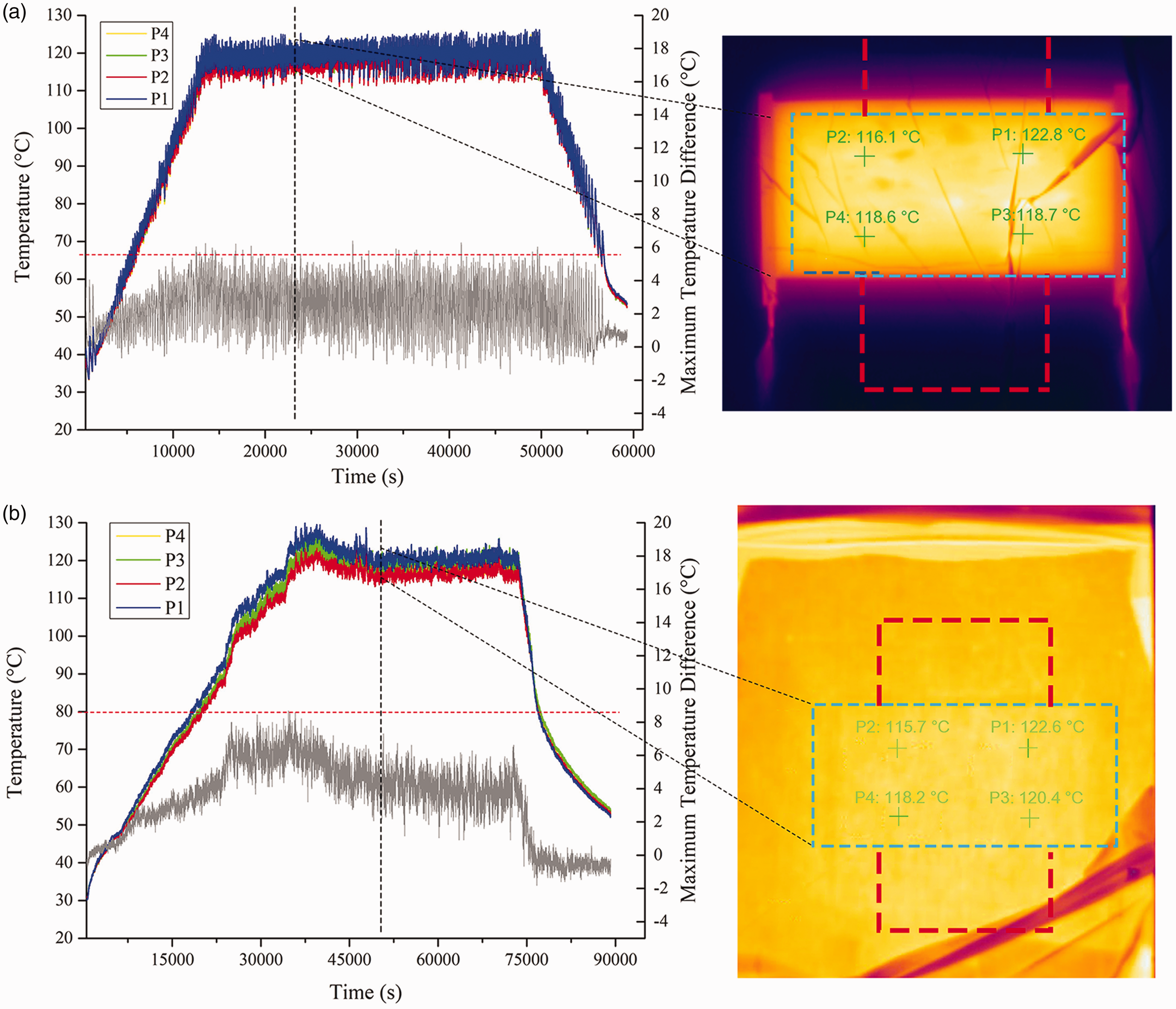
Temperature curves and the infrared profile of (a) SRE repairing (b) electrical blanket repairing process. SRE: self-resistive electrical.
Comparing the two infrared profiles, it can be seen from Figure 5 that the industrial-grade thermal blanket achieved a uniform temperature distribution field. The temperature distribution of SRE heating was also considerably homogeneous and even better. The maximum temperature difference
Degree of cure comparison
Differential scanning calorimeter was used to measure the residual exothermic peak of different repaired samples. The totally uncured prepreg was firstly measured, in which the exothermic area of 94.15 J/g was obtained. The typical heat release curves of DSC of samples are shown in Figure 6. There was no obvious exothermic peak for all the samples, which means that the CFRPs including the patches have been completely cured. Whereas, there was still a small exothermic peak of the blanket repaired sample. Average degrees of cure for three types of samples are shown in Table 1, which indicates that the SRE repairing process achieved a slightly higher curing degree, but this difference has no effect on whether the curing reaction was complete or not.
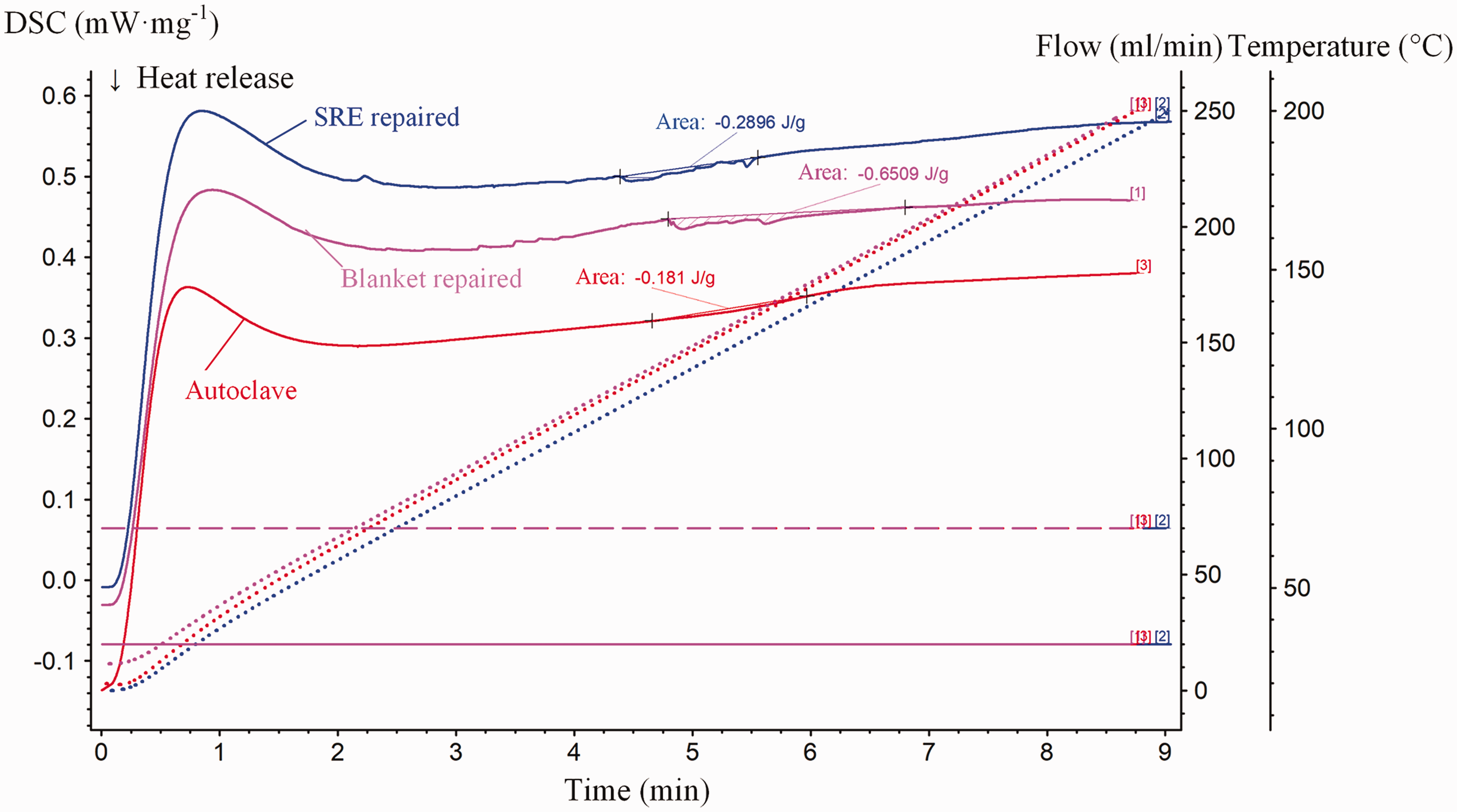
Typical heat release curve of DSC of samples.
Average degree of cure of three types of samples.
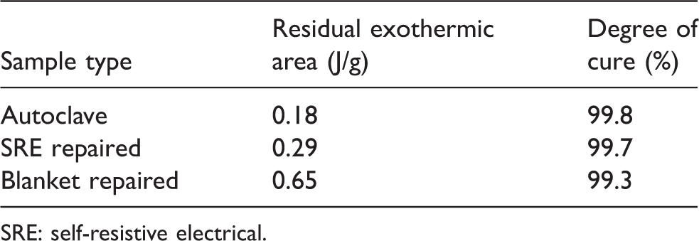
SRE: self-resistive electrical.
Cross-section morphology and void content analysis
The cross-section morphology of the samples was observed by optical microscope at the central section, by which the void content of samples was calculated and is shown in Figure 7. Samples cured by autoclave achieved the highest quality and its average porosity was only 0.65%. However, the porosity of both SRE and blanket repairing was close to 2.0%, which is due to the repair processes were under one atmospheric pressure and the air could not be effectively released. The average porosity of the SRE repairing samples was slightly lower than that of the blanket repaired samples, but the value of porosity distribution showed a larger range. The heating rate of the SRE repairing process was three times that of the blanket process, which means that the SRE repairing process only had the shorter resin flow time. This indicates that the fiber themselves as the heating source produced a relatively uniform temperature field, which may be more conducive to air expulsion. As illustrated in microscopic images of the cross-section, the black and white stripes were observed in all types of samples because the stacking sequence of [0°/90°] was applied. For the undamaged samples, the stripes were evenly distributed and the dividing lines were relatively straight, in which no obvious dark holes were found. Dissimilarly, there was an area of two contiguous white stripes marked by the blue fame both in SRE and blanket repaired samples, which was because that the bottom patch prepreg was parallel to the surface prepreg of the milled body laminates. However, the quality of the contact surfaces was different. For blanket samples, there was a blurring black gap between the two white stripes. A few numbers of void holes were found in the blanket repaired patches. SRE-cured samples had the stripes of distinct color, which means the cure state of SRE-cured patches was acceptable. Besides, there was only a tiny black gap between the body laminates and patches, and that means the even curing process achieved a satisfactory interlayer bonding strength. Conclusion of sectional morphology analysis was also confirmed by the further mechanical performance tests.
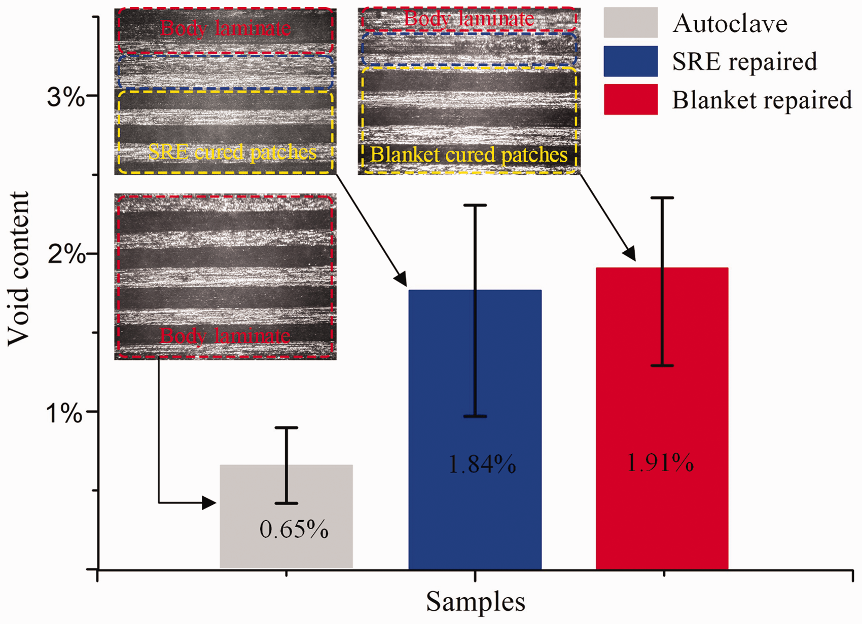
The void content column chart of different samples.
Flexural and interlaminar shear performance comparison
The flexural and interlaminar shear tests were respectively conducted, and the performance comparison and the results analysis are as follows.
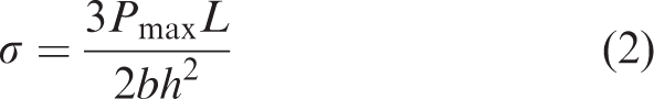
In the flexural test, the beam samples were destroyed by three-point compression, and the flexural strength can be calculated as follows
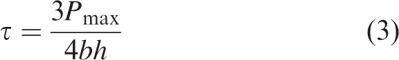
(a) Typical strength–time curves under (a) flexural load and (b) interlaminar load.
In Figure 8(a), for the flexural curves, the sharply buckling behavior accompanied by a crack sound was finally observed after an approximately linear increases stage in all the tests. For autoclave cured samples, a small fluctuation appeared in the flexural curves as circled in the black dashed ring, and the failure could be found on the samples’ upper surface, which means the compressive cracking of the fiber was the major failure mode. Autoclave cured samples achieved the flexural strength of 1344 MPa. For SRE and blanket repaired samples, the main failure was the delamination between the body laminates and cured patches, and the curves dropped rapidly when the delamination failure occurred. This shows that the bonding performance of the repaired samples at the patch-body laminate interface is lower than that of the original parts. But from the curves, the SRE-repaired sample had the longer bending displacement and achieved slightly higher flexural strength compared to blanket repaired one. Differently, as shown in Figure 8(b), the ILSS of blanket repaired samples was slightly higher than that of SRE-cured sample, but their maximum value was basically at the same level. A small number of fluctuations both occurred before the failure in the tests of SRE and blanket repaired samples, which can be attributed to the multiple upper layer crush and interlayer delamination.
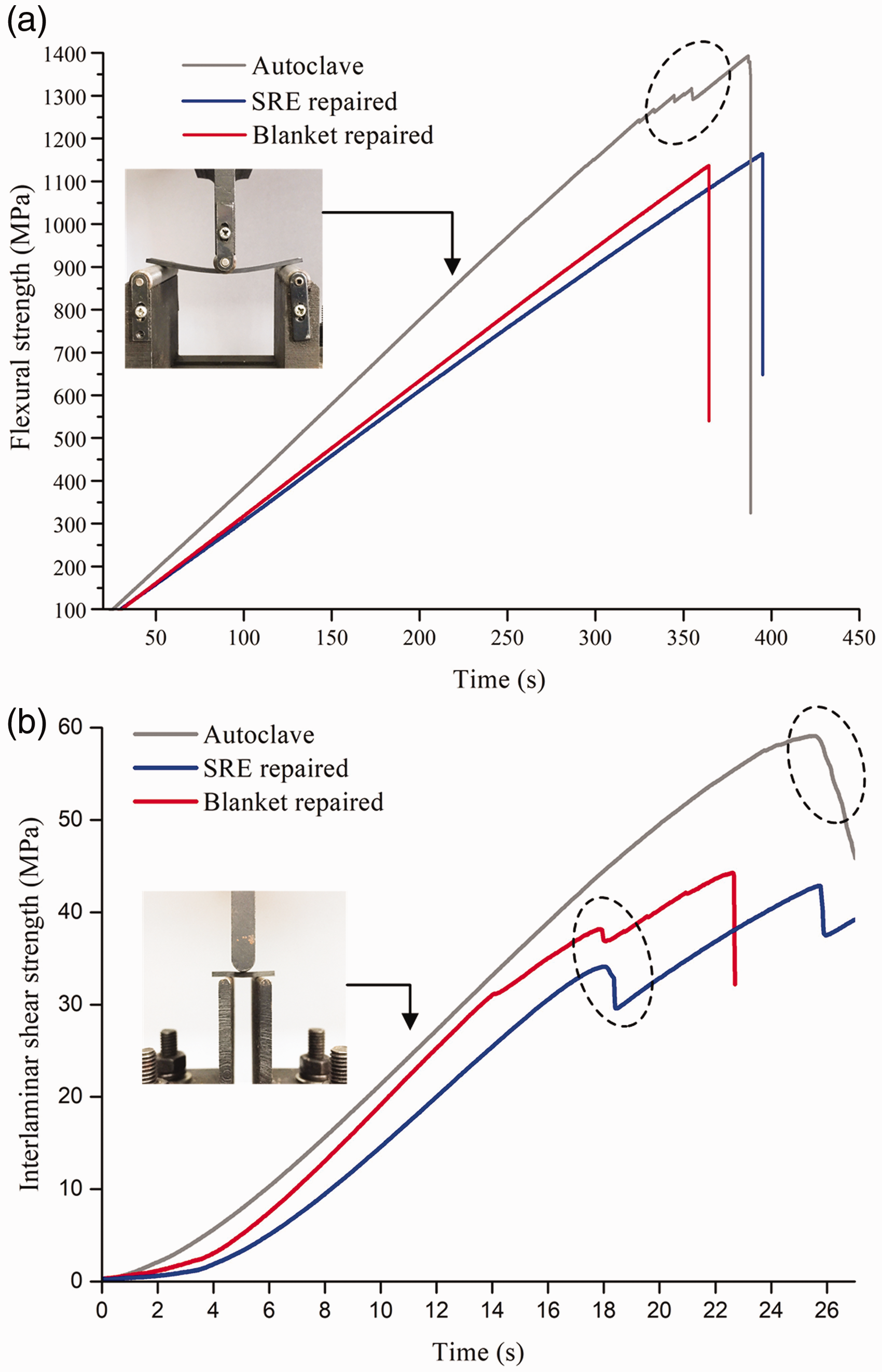
The column chart of the average mechanical strength is shown in Figure 9(a). In general, it was impossible to achieve 100% recovery ratio after field maintenance for CFRPs laminates. But for the rapid back to service of aircraft, the recovery ratio of 60%–80% was acceptable for some of the non-bearing parts.40,41 Overall, SRE repairing process achieved the same or even slightly higher repairing quality as the blanket repairing process, but only cost 62% repairing period and 58% repairing energy of the later one. From Figure 9(b) to (d), the bending fracture microscopic images are shown and compared. For the autoclave cured undamaged sample, except a few number of interlayer stripping, the 0° fiber snap fracture can be also found. This indicates that the interlaminar bonding strength was strong enough so that the axial fiber was crushed. In the image of SRE and blanket repaired patches, not only the interlaminar but also the in-plane fiber bundles were separated. This indicates that the interface bonding property of the repaired sample was inferior if there was only vacuum pressure applied.
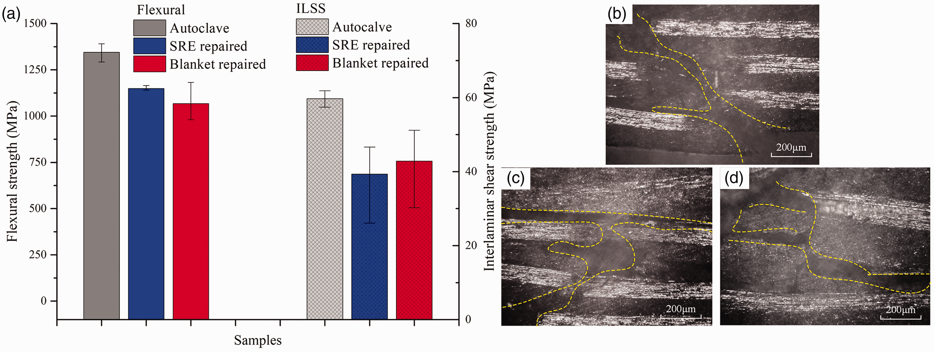
(a) The column chart of the average flexural and interlaminar shear strength of different samples, the bending fracture photomicrographs of (b) Autoclave, (c) SRE repaired and (d) blanket repaired samples. SRE: self-resistive electrical.
Table 2 gives the average performance recovery ratio of samples repaired by the aforementioned two repair methods. Both repair methods met the performance recovery ratio requirements of the field rapid repair, and flexural property of SRE repaired sample had the highest recovery ratio of 85.48% but the inferior ILSS recovery ratio of 65.89%. After eliminating the influence of experimental error, this result can be explained as follows. Because that the bending failure of all the repaired samples is the patch-body laminate interface delamination and the flexural strength of SRE repaired sample was higher, this can be considered that the interface boding strength was improved by the self-heating effect. To be specific, comparing to the traditional external heating methods, the fiber self-heating can lead to a higher temperature near the interface area, which may cause a relatively higher curing degree of the resin around the bonding interface.
The mechanical properties recovery ratio of the samples repaired by different process.
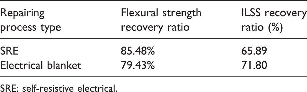
SRE: self-resistive electrical.
Conclusions
In this paper, the method of SRE heating to rapidly repair CFRPs parts was investigated. The portable SRE repairing equipment with automatic temperature control unit was firstly invented to achieve the SRE repairing process, by which the minimum temperature lag can be controlled within ±5°C. The temperature distribution in processes was observed by the thermal infrared imager, and SRE process achieved a maximum temperature difference within 6°C during the dwell of 120°C. Comparison repair experiments of including SRE and the electrical blanket were conducted. On the whole, SRE repairing process achieved the same or even slightly higher repairing quality as the blanket repairing process, but only cost 62% repairing period and 58% repairing energy of the later one, which was because that only the patch material was heated by themselves. The flexural and ILSS of SRE repaired sample had the performance recovery ratio of 85.48% and 65.89%, which met the requirements for rapid field maintenance of CFRPs structure. Due to the carbon fiber which was the heat source, the resin around the patch-body laminate interface area was heated to relatively high temperature, which improved the cure degree of the surrounded resin and further enhanced the interface bonding strength. SRE repairing method reduces the complexity of field repair equipment, and increases the repairing quality, which might be used in other applications with more demanding environment, such as the space repairing or self-repaired material. In addition, the electrode type in SRE repairing process needs to be further investigated for different types of repairing material, since the heating property will vary depending on factors such as the patches’ geometry, temperature and outer pressure, etc.
Footnotes
Acknowledgements
The authors sincerely appreciate the continuous support provided by our industrial collaborators.
Declaration of conflicting interests
The author(s) declared no potential conflicts of interest with respect to the research, authorship, and/or publication of this article.
Funding
The author(s) disclosed receipt of the following financial support for the research, authorship, and/or publication of this article: This work was supported by National Natural Science Foundation of China (Grant no. 51775261) and Postgraduate Research & Practice Innovation Program of Jiangsu Province (KYCX18_0319).