






Abstract
In the automated fiber placement process, the continuous placement paths need to be discretized into a finite number of path points because the laying head cannot continuously trace the predetermined curved path. However, the discretization of the placement path, which is a spatial curve, will inevitably introduce error. In this paper, an improved path discretization algorithm is proposed for the fiber placement of complex double-curved structures. Firstly, the discrete error was decomposed into normal direction and binormal direction, and they are correlated with the laying process and their influences on the laying quality are discussed, respectively. Secondly, the relationship between the binormal error and the overlap of the tow is analyzed with differential geometry, and the influence of the normal error on laying force is discussed by the pressure experiment and the finite element method. Finally, the improved path discretization algorithm has been verified on double-curved surface and compared with the traditional path discrete algorithms. The results showed that the number of discrete path points decreases by 45.8% on average compared with the chordal deviation discretization algorithm and by 63.1% compared with the equal-arc discretization algorithm.
Keywords
Introduction
Due to its advantages in weight reduction, fatigue resistance, corrosion resistance, crack growth retardation, sound insulation and noise reduction, wave absorption and wave transmission, composites have become an important aviation structural material.1,2 The application of composites in aircraft has been gradually extended from sub-load-bearing structures (hatches, fairings, stabilizers, etc.) to main load-bearing structures (wings, fuselages, etc.). The application of the large-scale composite structures has become an important development trend of aircraft manufacturing and is one of the important indicators to evaluate the advanced level of aircraft.3–5 With the development of composite material manufacturing technology, it has changed from traditional manual manufacturing to automatic manufacturing, including automated tape placement and automated fiber placement.
Since the composite component is made of additive material rather than traditional removal material, its processing process has attracted much attention. The processing process for the automated fiber placement mainly refers to laying technology and path planning. The laying technology mainly includes laying speed, laying temperature, laying force, ambient temperature and humidity, and roller performance. In addition, path planning generally consists of three distinct phases: (1) determining the placement path on the mould surface; (2) discretizing the placement paths and deriving tangent and normal vector information of path points; (3) post-processing the path points data to produce executable NC commands for the machine tool controller.
Many scholars have studied the effect of laying technology on laying quality. Rao et al. investigated the influence of compaction load, layup speed, and temperature on the adhesive properties. 6 Nima Bakhshi and Mehdi Hojjati studied the influence of the stiffness and architecture of the compaction roller on the laying quality. 7 Jinxiang Cheng et al. studied the influence of the attitude of compaction roller on automated fiber placement defects and demonstrated that it can improve the laying quality by the attitude fine-adjustment of roller. 8 Path planning has also attracted a lot of attention from many researchers. Most researchers focus on placement path generation algorithms, which include the initial path and offset path generation.9–12 And there are also studies about placement path evaluation. Cong Zhao et al. proposed fiber path layup quality and evaluated path based on prepreg tow deformability on free-form surface. 13 However, path discretization has received little attention as a part of path planning, which also has great impact on laying quality. The determination of the forward step is one of the most important steps in the path discretization. 14 There are three approaches to determine the forward step length of the traditional CNC machining so far: iso-parameter, equal-chord length, and chordal deviation.15,16 Iso-parameter method and equal-chord length method have not been widely used because of their own limitations, that is, the deviation is often beyond the tolerance for complex tool path geometry. Chordal deviation method is widely used because it can adapt to the change of path geometry and keep the error within the specified range. 17
All the approaches mentioned above are all approximations of the tool path, which have more or less deviations. There are a lot of investigations on how to reduce these deviations by considering some constraints, such as surface geometry, machine configuration, and so on. Yan et al. proposed an adaptive step length method to effectively control the cutter contact path error considering the nonlinear errors caused by machine configuration and nonlinear motion. 18 Hwang and Ho considered that the traditional tool path algorithms are not reasonable because they only take the surface geometry into account, and so they presented an improved algorithm for the forward step length determination, which considers both the surface geometry and the NC structural parameters. 19 Tutunea-Fatan Feng put forward a new and accurate method to evaluate errors by considering both the configuration of the kinematic chain of the CNC machine and surface geometry. 20 In addition to the constraints of machine configuration on the basis of the previous surface geometry, there are also constraints about the quality of workpiece and machining efficiency in the determination of the forward step length. Li et al proposed an improved method of tool path discretization for five-axis sculptured surface machining, which ensures maximized material removal rate and no gouging to the machined surface. 21
The above algorithms are generally about the determination of forward step length in the traditional five-axis CNC machining, which effectively reduce the approximate error. However, these optimization algorithms are not always very suitable for the placement path discretization, because there are certain differences between the laying of composite materials and the CNC machining, and the criteria for evaluating the surface quality are not consistent. The CNC machining generally requires high surface quality of the workpiece, while composite material components generally have higher requirements on the laying process and consist of many layers, dozens or even hundreds of layers. The use of traditional forward step length determination algorithm to discrete placement path will inevitably lead to a large number of data redundancy and may not be able to meet the requirements of laying quality. Therefore, the path point data can be greatly reduced if the forward step length is as large as possible when the laying quality is satisfied. So far, however, there is little attention been paid to the placement path discretization. This paper aims to develop an improved and optimized method to discretize the placement paths. The improved placement path discretization is achieved by considering the laying quality, which includes the normal compaction and binormal defect.
Effect of path discretization on laying quality is described in the following section. Then, discretization algorithm for placement path of the complex double-curved surface is presented. Implementation and analysis are described in the penultimate section, while the conclusions are drawn in the final section of this paper.
Effect of path discretization on laying quality
The laying quality of composite preformed body is very important for automated placement process, which is closely related to placement path planning, laying equipment, and laying technology and will directly affect the final mechanical properties of composite components. In this paper, we only study the influence of path discretization on the laying quality which is one process of placement path planning, and then determine the improved path discretization algorithm. The related laying process is assumed to be free of any other types of error introduced by laying equipment and laying technology.
The laying equipment mentioned above was independently developed by our research team. Due to the adoption of linear interpolation mode, the placement path is not a continuous curve but approximated by a series of discrete lines. The direct effect of path discretization is the geometric error relative to the original path curve. The improved path discretization algorithm establishes the relationship between the geometric error and the laying quality, and then determines the allowable range of the error according to the laying quality requirements. The detailed analysis of the errors caused by path discretization is presented in the following part.
Given the equation of the mould surface
Taking the curve
In this paper, the maximum distance between discrete segments and curved segments is defined as the spatial approximation error. As shown in Figure 1, the approximation error

Deviation analysis diagram of path planning.
The compaction quality and binormal defects are two important aspects that are considered more in the laying quality. Different from the traditional cutting process, the influence of the discrete error of the placement path of composite material has directivity. The normal error is related to the laying force, and the binormal error is related to the binormal defects. Therefore, the geometric error is decomposed into normal error and binormal error.
Under the orthogonal coordinate system with
The normal error
The analysis of the influence of normal error
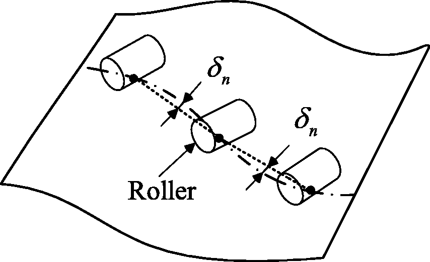
Effect of normal error on laying force
In the laying process, the placement head will compress the tow onto the mould surface with a certain laying force
Deviation analysis diagram.
For convex and concave surfaces, the normal error has different effects on the laying force. When planning path in a plane, the normal error of the path is zero and does not affect the compression force. When laying on the convex surface, the existence of normal error leads to the local shortening of cylinder elongation, which leads to the increase the pressure of cylinder and the increase of local compression force, and the tow can easily deform under excessive compression force. For the concave surface, the existence of normal error leads to the local lengthening of cylinder elongation, which leads to the decrease in the pressure of cylinder and the decrease of local compression force, and the pre-impregnated tow may be peeled off the mould surface under the insufficient compression force, resulting in bridging phenomenon, and reducing the laying quality.
Effect of binormal error on binormal defects
In order to avoid overlap between two adjacent tapes which refer to two courses of tows, there is usually an interval
Due to the geometric complexity of placement trajectory, the discrete paths will deviate
In order to better express the influence of the binormal error, we take a plane as the laying surface, and then the path discrete error is only the binormal error. As show in Figure 3, firstly, two adjacent placement paths and their theoretical tow boundaries are generated, and then the placement paths are discretized to obtain the actual paths. When the sum of error

The influence of binormal error. (a) Theoretical placement path and tow boundary, (b) path discretization of placement path, and (c) actual placement path and tow boundary.
Therefore, it is necessary to control the binormal error
Discretization algorithm for the path on the complex double-curved surface
The surfaces laid on aircraft components are generally complex double-curved surfaces. Therefore, during the discretization of the placement path, the influence of the overlaps caused by the binormal error and the influence of the normal error on the contact pressure need to be comprehensively considered.
Calculation of normal error
Determination of appropriate contact pressure interval
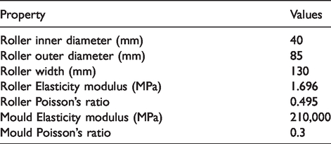
The contact pressure on the tow is obviously different when the same laying force acts on different types of compaction rollers, which is due to the different contact area between the roller and the mould surface. In addition, the contact pressure of the tow is not uniform along the axial direction of the compaction roller under a certain laying force when laid on a non-planar surface, which is very common because the laying surface is generally an uneven surface. Therefore, the contact pressure is used as one of the laying technology parameters in this paper. The normal error value
Main parameters of the roller and mould.
The experiment was carried out on our own tow laying platform which is shown in Figure 4. And the experiment conditions are as follows: Ambient temperature is 20°C, humidity is 30%, laying speed is 30 mm/s, laying temperature is 25°C. The different laying force were provided by controlling the pressure of the cylinder, seven input pressure values are 0.05, 0.1, 0.15, 0.2, 0.25, 0.35, and 0.45 MPa, whose corresponding laying force are 100, 200, 300, 400, 500, 600, and 700 N. Repeated experiments are performed under the same experimental conditions. The experimental results show that the laying effect of pre-impregnated tow is ideal, while the laying force is in the range of 200–600 N. And then the contact pressure interval (0.1–0.35 MPa) is acquired, which is calculated according to the contact area. For the above phenomenon, 0.1–0.35 MPa was chosen as a suitable contact pressure interval (as shown in Figure 5).

The experimental platform for tow laying.

Laying quality with different pressures.
Determination of suitable laying force interval
According to the analysis in the previous section, contact pressure is more suitable than laying force as one of the control parameters of laying technology. When the laying surface is flat, the optimal laying force under the specified contact pressure can be directly calculated by the empirical formula. However, for curved members, the relation between the contact pressure and the optimal laying force cannot be obtained directly due to the complexity of the contact area. Due to the non-uniformity of the contact pressure on the curved surface, the suitable range of laying force is smaller than the planar components in order to ensure that each point in the contact area has a good compaction quality. Therefore, it is necessary to determine the relationship between the curvature of the laying surface and the suitable laying force. However, it is relatively difficult to obtain the relationship between the curvature of the laying surface and the laying force, since the laying surface is in surface contact with the compaction roller instead of line contact or point contact.
In this paper, the appropriate laying force of different surfaces were obtained by means of simulation. For a general surface, the curvature in the contact region is not constant. In order to simplify the analysis, the contact area is approximated by a cylinder whose curvature is the normal curvature at the path point on the curved surface along the axial direction of roller. And the effectiveness of the simulation was verified by experiments. The finite element models of the compaction roller and mould were established, as shown in Figure 6. The material of the rubber cover of the roller is silicone rubber, whose stress and strain behavior can be considered linear when the deformation is less than 25%. 22 In order to improve the calculation efficiency, the mandrel of the compaction roller and the mould was constrained as “rigid body,” and the rubber cover was regarded as a linear elastomer. By adding the fixed constraint of the surface and applying concentrated force on the compaction roller axis to simulate the pressing process of the compaction roller, the relationship between the curvature of the mould surface and the laying force can be obtained. Material parameters of each part are listed in Table 1.

Finite element model of compaction roller on different surfaces.
Through the change of the radius of curvature of the cylindrical surface, the situation that the compaction roller is in contact with different mould surfaces can be simulated. By changing the concentrated force, the axial contact pressure distribution on the contact surface of the compaction roller can be obtained under different concentrated force. The width of the pre-impregnated tow used in the experiment is 6.35 mm, the width of tow channel is 6.5 mm, and the number of a course is 16, so the contact pressure within the width of 104 mm was required to be in the range of 0.1 to 0.35 MPa.
The pressure distribution curves of the contact area of the compaction roller were drawn according to the results of finite element analysis. When the minimum pressure value is 0.1 MPa within 104 mm width range, the force is defined as the minimum laying force
When the surface to be laid is a convex surface, the curve

The maximum and minimum allowable laying force of convex surface.
When the surface to be laid is a concave surface, the curve

The maximum and minimum allowable laying force of concave surface.
Experimental verification of the laying force interval
In order to verify the correctness of the finite element model, the plane, the convex mould surface with a radius of 900 mm and the concave mould surface with a radius of 900 mm were selected to carry out the experiment. And the experimental contact pressure value and the pressure value of the corresponding finite element model were compared. The experimental device is shown in Figure 9.

Test device for different mould surfaces. (a) Concave of radius 900 and (b) convexity of radius 900.
The comparison of the contact pressure distribution of the compaction roller between the experiment and simulation in the finite element model is shown in Figure 10.

The comparison between simulation pressure value and experimental pressure value under different force. (a) Plate under different force, (b) convex under different force, and (c) concave under different force.
Calculation of normal error
The existence of normal error will cause the fluctuation of cylinder elongation, and then cause the fluctuation of air pressure inside the cylinder. At this time, the air pump will balance the air pressure inside the cylinder by filling and releasing air in the cylinder. However, due to the response speed of the air pump, the laying force will fluctuate to some extent, which will affect the laying quality. It is assumed that the laying force is set to
According to Boyle’s law, we can get the following relationship
The influence of normal error on laying quality is considered based on the idea of equal error, and the normal error is associated with laying force
The control coefficient
Calculation of binormal error
In the general case, the overlaps in the placement process refer to the repeated part of the space position of two adjacent courses of tows. In this paper, we assumed that the objects we want to discretize are placement paths without gap or overlap defects in theory, and the overlap proposed above was introduced by path discretization and machine error. If the width of overlaps between adjacent paths is directly calculated, it will be very complicated because there is no definite position relationship between discrete points of adjacent paths, and it is difficult to get the quantitative relationship between overlaps defect and discrete step size. Therefore, the deviation between the discrete path and the theoretical path is taken as the index to evaluate whether the overlap will occur. Taking the fuselage panels as an example, the design models are usually compound-free surfaces, whose parameter equations are difficult to obtain. This paper makes two simplifications in the calculation of the width of overlaps caused by binormal error:
(1) Based on the Frenet frame, the path curve is approximated by the local normal form; (2) the overlap region on the mould surface is approximated by the projected region on the tangent plane of the mould surface.
As shown in Figure 11, A is the coordinate reference frame XYZ,

Deviation analysis diagrams of tow of binormal direction.
Let
The torsion expression at
The Taylor expansion of
Since the derivative of each order of
Ignoring the high-order term, the approximate equation of curve
The curve described by the approximate equation has the expression in the Frenet frame
Define a new local coordinate system B.
After conversion, let the coordinates of the point
The projection of the approximate curve on the osculating plane
The maximum width of single overlap on the tangent plane can be described as
In the laying process, overlap width is generally allowed to be very small, and the overlap is not allowed in most cases. Therefore, the maximum overlap width
Discretization of the placement path
According to the above analysis, when the laying surface is more complicated, the effects of equal-arc length discretization and chordal deviation discretization on laying quality are more obvious. Therefore, the improved path discretization algorithm, which considers binormal overlaps and normal compaction, was proposed. The idea of this algorithm is to improve the actual laying quality on the basis of ensuring the geometric accuracy of the path. The flowchart of the algorithm above is shown in Figure 12; the specific steps can be described as follows:

Flowchart of path discrete algorithm.
Step 1: Calculate the minimum discrete step size
Step 2: Discretize the path with
Step 3: Input related parameters
Step 4: Calculate the normal error
Step 5: Determine whether the normal error value
Step 6: Only change the parameter j, let
Step 7: Save the previous path point, only change the parameter i, let
Step 8: Determine whether
Implementation and analysis
In order to verify the feasibility of the path discretization method, this paper develops a program module based on the CATIA secondary development technology and realizes this path discretization algorithm. Taking the double-curved surface as the laying surface, it is assumed that the placement path satisfying the requirements has been planned, as shown in Figure 13. The improved path discretization algorithm was firstly adopted to discretize the path, and corresponding NC files were used for laying experiments to observe the laying quality and then verify the effectiveness of the improved path discretization algorithm. Figure 13 shows the laying path of 16 tows, with tape’s interval of 0.5 mm. In order to ensure no overlap defects, the allowable binormal error is set to 0.05 mm after considering machine positioning accuracy and repeated positioning accuracy. The allowable value of force change of laying equipment adopted in this experiment is 5%. Here, we set the maximum allowable value of force change of the laying equipment to 2%, excluding random error and machine positioning error. The results of the laying experiment are shown in Figure 14, and then we can evaluate the effectiveness of the proposed algorithm according to the laying quality. There are laying result diagram of whole ply and three local diagrams of key part of the ply.

The diagram of placement path.

The diagram of experimental result.
Next, we use the traditional path discretization algorithm commonly used in five-axis machining to discretize the placement path, which includes equal-arc discretization method and chordal deviation discretization method. The single-step length adopted in the equal-arc discretization method must satisfy the requirement that the entire path has no laying defect and the step length is determined by the most dangerous part of the path, which is the part of the path most prone to produce laying defects. In order to meet the above path discrete requirements, the minimum step size of the improved path discretization algorithm is set as the step length of equal-arc discretization method. In addition, the chordal deviation method needs to ensure sufficient compaction and no overlap defects, and the deviation value can only take a smaller value of the normal deviation value and the binormal deviation value. Finally, we compared the discrete results of three path discrete algorithms under the premise of sufficient compaction and no overlap defect, and the comparison results are shown in Figure 15.

Comparison diagram of discrete results of different algorithms.
As can be seen from the figure, under the deviation value set in this paper, the improved discrete algorithm reduces the discrete path points with equal-arc discretization method by 63.1% on average, and the improved discrete algorithm reduces the discrete path points with chordal deviation discretization method by 45.8% on average. The corresponding NC data file size will thus be proportionally decreased. Linear interpolation uses a set of short lines to approximate the path curve, and a certain speed mutation will occur between the two short lines. The reduction of discrete path points will reduce the number of straight segments, reduce the speed mutation, and improve the placement efficiency to a certain extent. In order to verify the above statement, the NC files corresponding to the three discrete algorithms were placed for comparing, and the results showed that the laying efficiency of the improved discrete algorithm was 25% higher than that of the discrete algorithm with equal-arc length, and 18% higher than that of the chordal deviation discretization method. Composite material components are generally composed of dozens or even hundreds of layers, so it can be seen that the improved path discretization algorithm is very meaningful for laying path discrete. In addition, it can be found that the number of discrete points of partial paths is consistent or relatively close, when the chordal deviation method and the improved path discretization method are adopted. The above phenomenon reflects a feature of the improved path discrete algorithm, that is, when the path is geodesic curve or plane curve, the discrete results of the improved path discretization method and the chordal deviation method are consistent, and when the path is close to geodesic curve or plane curve, the results of the two path discrete algorithm are relatively close. However, automated fiber placement technology is generally used for complex curved surface components, and the proportion of geodesic or plane path is very small, so the improved path discrete algorithm is more suitable than the chordal deviation method.
Conclusions
The problems caused by the linear interpolation method in the placement equipment are discussed, and two parameters of the errors in binormal direction and the normal direction are introduced in the discrete process of the path. The impact of the two parameters is analyzed separately.
The suitable contact pressure interval of a certain type of compaction roller is determined by experimental method, and the pressure-sensitive film is used to measure contact pressure.
In this paper, the discrete errors are decomposed into normal direction and binormal direction, and then the two direction errors are closely related to the laying process; the respective constraints are determined. An improved path discretization algorithm based on the constraints above is proposed. The algorithm is implemented on complex double-curved surfaces.
Compared with the traditional path discrete algorithm, the improved path discretization algorithm greatly reduces the number of discrete path points, and then reduces the size of corresponding NC file. In addition, it can improve the placement efficiency to some extent.
In this paper, only the influence of path discretization error on lay quality is considered, and the influence of path discretization error on the motion performance of the laying machine is not considered. If all these factors are taken into account, the path discretization algorithm can be further improved.
Footnotes
Declaration of conflicting interests
The author(s) declared no potential conflicts of interest with respect to the research, authorship, and/or publication of this article.
Funding
The author(s) disclosed receipt of the following financial support for the research, authorship, and/or publication of this article: This research was sponsored by the Fundamental Research Funds for the Central Universities (No. 2019FZA4001).
