
Abstract
The cross-sectional degradation of steel transmission tower members due to corrosion has been one of the major issues in the transmission line system. The degradation of appearance of the material has also been seen because of corrosion. Therefore, there is a need for a less corrosive and high strength alternate material for transmission towers. It seems in recent years that alternate materials have been needed to replace steel which have low maintenance cost and good resistance to corrosion. The advantages of composite transmission towers are fire resistant, high stiffness, durability, high strength, moderate ductility, rigidity, easy to assemble and economical. The present study has made an effort to evaluate the performance of composite transmission tower. The glass fibre polyamide composite material has been used as a structural material. First, a finite element tower model of 132 KV has been set up in Structural Analysis and Design Software as glass fibre polyamide structural material as per transmission tower design guidelines (Code for Transmission tower design, IS 802.1.1.1995, Bureau of Indian Standards). Second, all the active loads like wind load on the body, wind load on conducting wires and ground wires, weight of conducting wires, weight of structure, weight of ground wires, weight of insulator and weight of line man with tools are calculated manually as per transmission tower design guidelines and applied in the finite element tower model. The stress distribution of the composite tower model has been simulated in Structural Analysis and Design Software and the results have been analysed. The broken wire condition (if one conductor is broken or earth wire is broken) has been innovatively considered in the present study. Results obtained in this article show that maximum induced stress on transmission tower member is less than the deign strength of glass fibre polyamide composite material. The glass fibre polyamide composite material has been found to be capable to withstand the maximum stresses induced due to different loading conditions considered in the study.
Introduction
The tall transmission tower has been used to support an overhead power line usually made of steel. The transmission tower is also called steel lattice transmission tower. They come in different shapes and sizes and are used for high voltage AC and DC systems. The heights of these towers range from 15 to 55 m. The literature reported that the materials other than steel including wood and concrete may be used for these tower structures. The transmission tower has mainly four categories which are terminal, transposition, suspension and tension type. Combining these basic functions some transmission towers have also been made in actual practices. The main aim of the transmission tower design is that the transmission tower has to carry the power carrying conductors to a safe height from the ground. Not only carrying the conductors to a safe height these towers also bear all natural calamities. Thus, the designing of transmission tower includes all engineering concepts equally.
The electricity transmission system (ETS) plays an important role to improve the civilization. It has been assumed that the improvement of economic and societal growth of any country directly depends on ETS. Extra-high-voltage towers are the most important parts of ETS for supporting overhead power lines. The regular functioning of the complete transmission system mostly depends on the security and safety of the towers. 1 These tall structures have mostly been constructed by galvanized steel (iron is being coated on steel through galvanization) which are angle section. The corrosion of steel towers has been one of the major disadvantages which can cause serious problems in the infrastructure. The cross-section of the L type members is reduced due to corrosion that leads to loss of the strength of materials. Hence the subsequent failure may occur to tower structure. The degradation of appearance of the material has also been seen because of corrosion. Therefore, there is a need of a less corrosive and high strength material for the transmission towers.
Polyzois et al. 2 theoretically and experimentally analysed the segment of fibre reinforced polymer tower under static and dynamic loading condition. Alshurafa et al. 3 studied the transmission tower made with glass-fibre reinforced polymer (GFRP) and evaluated its structural performance with static loading condition under secured mass of 163 kg of 1 kW vertical turbine. Using different failure theories they also developed a nonlinear finite element method (FEM) for analysing the failure load. 3 Li et al. 4 used two different composite materials in 110 kV tower to verify the basic performances of composite materials, showing that the composite material towers have widespread prospect in certain application through a broad analysis of technology, economy and associated aspects. Transmission towers were found to be mostly excited due to various effects, viz. wind loads and earthquakes.5–7 Because of complex geometrical configurations, the dynamic characteristics of towers are nonlinear in character. Due to the power cable’s vibration, dynamic loadings are generated in the transmission towers that lead to the failure of transmission tower.8–10
Abdou and Fadl 11 evaluated the performance of composite material elements that may be replaced with steel materials that are unlawfully removed from transmission towers. The composite redundant members used as structural elements in towers are also analysed by FEM for analysing the performance of 400 kV transmission tower, for their tensile and compressive strength. 11 Ramirez et al. 12 developed a methodology to evaluate the feasibility of replaceable metallic members by composites based on their compressive stresses. Commercially available four polymeric materials (polyester pultruded fibreglass, vinyl ester pultruded fibreglass, epoxy carbon fibre trusses and polyethylene terephthalate) may be used for replacing 0.5-3.0 m stolen or removed steel as alternative materials.12,13 The simulation of tower behaviours using FE model was found to be very challenging: cable vibration itself was instituted to be difficult to model.14,15 Hence, some simplified models that take into consideration the coupling characteristics were established for cases of transmission tower and line systems. 16
Bhowmik et al.17,18 have made an effort to analyse the performance of transmission tower of composite, modelled in a standard analytical platform for analysis of stability and strength under different loading conditions considering real life applications. An evaluation was done to reveal the maximum tensile stress in members close to the base of structure to be 210 MPa, whereas the breaking stress (theoretical) of the composite is 1200 MPa which is found to be much higher than tensile stress that occurred at the transmission tower under various load conditions, hence, concluded to be a stable composite tower.19,20 Supian et al. 21 studied durability as well as degradation of GFRP cross arm of transmission towers. An evaluation has also been done, which, when the GFRPs were exposed to the outdoor environment, the mechanical strength did not decrease with the enduring environmental surroundings. They concluded that the fibreglass cross arm showed significant improvement for durability with the effect of moisture to replace the traditional conventional timber cross arm. 21 Bhowmik et al.17,18 studied about the dynamic characteristics of carbon fibre epoxy (CFE) composite transmission tower with the use of commercial software. The authors summarized that the first vibration period was 5% more than the period that was estimated by an experienced formula. It was also found that the period of free vibration for transmission tower with conventional steel material is between 0.008 and 0.011 of the tower’s height. The period of free vibration transmission tower with CFE composite is in between 0.003 and 0.014 of the tower’s height. 17 Using a standard analytical platform and numerous modal tests of tower structures under free boundary conditions with a distributed mass model has been developed because of the limited study of the free vibration characteristics of transmission towers in literature.22–24 The dynamic analysis of transmission tower structure could be done through the identification of vibration modes of natural frequency of the tower structures by modal testing and FE simulation.25–28
Bhowmik et al.17,18 studied about the dynamic characteristics of Carbon Polymer Nylon 66 (CPN 66) composite made transmission tower using commercial software. The authors summarized that the first vibration period was 35% that was found more than the period determined by an experienced formula. Also, it was found that the free vibration period of transmission tower of conventional steel material is between 0.008 and 0.011 of the tower’s height, whereas the period of free vibration for CPN 66 composite transmission tower is in the range of 0.004–0.013 of the tower’s height. 18 Vladimir et al. 29 analysed the performance of GFRP as material to transmission towers. They have summarized that the GFRP structures are not suitable for 110 kV due to its poor stiffness. They also modelled tower poles considering GFRP and steel–GFRP materials and showed that GFRP revealed much better stiffness than that of hybrid steel–GFRP towers. Bhowmik et al.17,18 using a standard analytical platform analysed transmission tower considering CFE composite material. The authors summarized that the first vibration period was 5% that was more than the period estimated by an experienced formula. It was also found that the free vibration period of transmission tower of conventional steel material is between 0.008 and 0.011 of the tower’s height, whereas the free vibration period of CFE composite transmission tower is in between 0.004 and 0.013 of the tower’s height. 30
Due to the continuous exposition of transmission tower members which are made of steel to hostile environment, the deterioration and corrosion is a serious concern. 31 The composite materials might be the solution for the transmission tower as alternative materials. Nowadays, composite materials have been used for transmission tower as alternative materials over conventional zinc galvanized steel material due to some distinct features, reported in the literature. Due to terrestrial environments, viz. wind, rain and in some areas salty environment, these metallic towers have been found to be corroding and subsequently damaging the structure. For prevention of further corrosion and the damage, composite materials are used in study of the feasibility of building the next-gen high voltage transmission towers. 29 Hence a special attention should be paid in the study of tower structures that are composed of a wide range of composite materials regarding strength and stability. In the present study, the performance of composite tower has been evaluated. Also, the strength and stability analysis of composite transmission tower has been carried out using standard finite element (FE) tool. First, a FE model tower was set up in Structural Analysis and Design (STAAD) platform considering glass fibre polyamide (GFP) as structural material. Second, all the active loads like wind load on the body, wind load on conducting wires and ground wires, conducting wires’ weight, weight of structure, weight of ground wires, insulator weight and line man weight inclusive of tools are calculated manually as per guidelines and that applied in FE tower model. The stress distribution of the composite tower model has been simulated in STAAD and the results have been analysed. The different load conditions including the broken wire condition (BWC) (if one conductor breaks or earth wire breaks) has been newly considered in the present study.
Transmission tower forces
In real life application, transmission towers face different forces. These forces are mainly divided into three vital categories: longitudinal, transverse and vertical loads. The loads which are directly affecting the transmission tower are discussed in subsequent sections.
Tension in the wire
The sagging of wire is the curvature shape of line cable between two adjacent towers. The sagging of wire depends on the surrounding temperature. It has been a necessity to calculate the sagging of wire to determine the height of tower at maximum environmental temperature. Sagging of wire at corresponding temperature may be calculated from tension in the transmission wire. The formula that may be used to calculate the wire tension is as follows

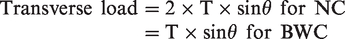
Action of transverse load
One of the most significant load acting on transmission towers is ‘wind load’ that has been considered. The load of wind on tower body, wire and insulator may be assessed by estimating the probable area of parts and multiplying the intensity of wind. The calculated wind load is then converted to point loads at centroid of a particular section. Transverse load also acts on tower body due to the deviation angle (angle between three adjacent towers). Transverse load due to the angle of deviation for both normal condition (NC) and BWC can be estimated by the following equation
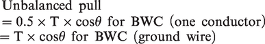
Action of longitudinal load
Longitudinal force acts on tower body owing to the unbalanced load. Here, it is to be stated that the unbalance force acted on the transmission tower after any of the conductor that might break because of some unwanted situations. The unbalanced pull may be estimated by the following formula
Action of vertical load
Vertical loads consist of weights of insulators, conductors, tower, line man for repairing and other accessories that are usually involved with transmission towers. The insulators’ weights are typically considered as per design parameters prescribed by the industry. The conductors’ weight may also be estimated by multiplying weight per unit length to the wire length. Tower weight can be calculated by weight of the material that is used for construction of tower structure.
Theory for stability testing of composite angle
Testing of shear capacity of composite angle
The shear force that acts separately on each face of angle section must be considered while testing the shear capacity of composite angle. The resulting shear force may be allocated into two parts that act on each of the faces, and every section is substantiated for either yielding or for buckling. The following equation may be used to calculate the yield shear capacity for leg section h (width) × s (thickness)

The below equation can be used for uniform shear distribution to estimate the elastic buckling shear stress of unstiffened leg section (h × s)
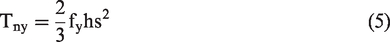
Testing of torsion capacity of composite angle
The below equations are used for unstiffened composite angle leg section to calculate the plastic uniform torque and first yield torque

The following condition must be satisfied for designing uniform torque

Where the nominal uniform torsion capacity, which is given by

Theory for combination torsion and shear testing of composite angle
The following equation must be satisfied when the unstiffened composite angle has been affected due to the combined effect of shear and torsion
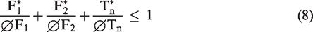
The design considerations that must be followed regarding design of transmission tower structure are listed as below for strength and stability:
The connection deformations must be considered which contribute to the structural displacements. Torsion and shear of structural members. The δ effects must be considered while designing the composite tower. Due to inelasticity of the structural member the stiffness is being reduced which effect the stability of structure is a matter of consideration. Geometric imperfection is an important consideration.
P-Δ or P-delta effect may be defined as the rapid changes of axial forces, overturning moment and ground shear due to the effect of critical lateral displacement to the tower structure. The P-δ effect is the deflection of members within a tier in multi-tiered structure, whereas P-Δ effect is the deflection of the tire of multi-tiered structure. The magnitude of these effects depends upon the initial displacement and deflection of members. The effect of P-Δ is considered to be nothing but a destabilizing moment. When the structure is loaded laterally, the destabilizing moment may be calculated by multiplying the horizontal displacement structure undergoes with the force of gravity. 32
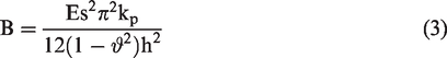
Composite materials – GFP
A composite is generally composed with two or more elements that are different either chemically or physically, in order to get improved properties of materials. For obtaining the composite material, the main elements in matrix are arranged. The reinforcement and the binder matrix are discontinuous and continuous, respectively. GFP is known to be a composite material made of a resin matrix that is reinforced with glass fibres. The strength-to-weight ratio is better and also anisotropic in nature. The high strength-to-weight ratio of composite materials comes from anisotropic nature of the resin. The anisotropic nature of GFP provides the strength and stiffness along with the fibre weave direction. For light weighing and more efficient designs, composite material is best suited for transmission tower material. In the present study, GFP is used as a structural material, and Table 5 shows the detailed property of GFP.
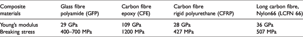
Steel is very sensitive to the hostile environment. By the continuous exposition of transmission tower to environments, there is concern of corrosion and deterioration. The corrosion and deterioration of transmission tower made of steel is mainly due to the presence of salinity, contaminants, etc. in the environment. Composite materials can fix these above stated issues properly. However, the UV degradation of composite materials is the major problem. This issue (UV degradation) can be overcome by including UV protection formulation during the manufacturing of composite materials. Temperature damage of composite material has not been reported yet. It may be mentioned here that the working temperature of these materials is much more than the ambient temperature. In the literature it has been reported that the estimated life of transmission tower made with composite materials is around eight years. Table 2 shows the different composite materials along with their detailed mechanical properties for transmission tower available in the market.
Design parameters for GFP composite transmission tower.
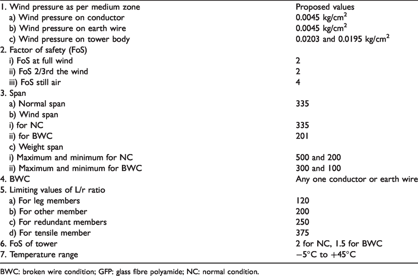
BWC: broken wire condition; GFP: glass fibre polyamide; NC: normal condition.
Alternative composite materials for lattice tower reported in the literature.
STAAD pro modelling of composite transmission tower
Basic assumption of STAAD pro modelling
To investigate the stability of composite tower, a nonlinear analysis has been carried out by using commercially available platform. The present study includes STAAD Pro for structural analysis of composite tower model. Under different loading conditions it estimates the axial stresses and the axial forces for each member of the composite structure model. Based on the standard code for transmission tower design, IS 802.1.1.1995, Bureau of Indian Standards, 33 the software verifies the design of composite tower model thoroughly. A 132 KV lattice transmission tower has been considered as objective tower in this study as shown in Figure 2. Tripura State Electricity Corporation Ltd, Tripura, India has shared all the relevant design parameters with us for this research (See Table 1). They provide us all the design parameters of 132 kV transmission tower and wires for their one particular transmission line set-up. However, this study is also applicable towards other type of towers. The tower structure is constructed by L sectional members which are connected by bolt joint. Member connections are not frictionless.It has been considered that working lines of tower member are always not coincided with centroidal axis of the member. Hence, at each joint, all of the working lines would not meet at a single point. Loads are applied at the joints with eccentricity. Figure 1 shows the flowchart of steps involved in FE analysis in STAAD. The fundamental suppositions of FE modelling are as follows:
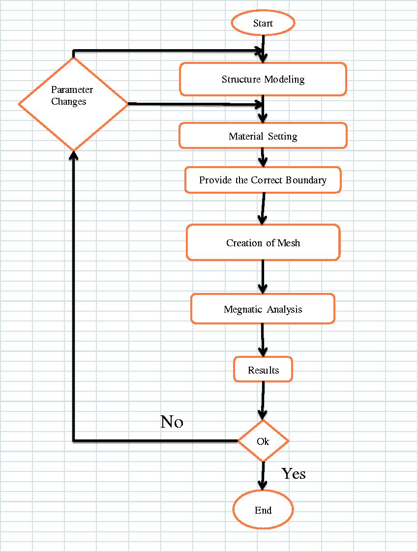
Flowchart of detail steps of FE modelling.
All the members should be straight and their cross-sections should not change along the length.
The material should be an anisotropic material.
Generally all members are connected by hinge joints.
Details of composite tower model
The composite tower has been modelled in STAAD Pro as 3D truss model. The base of tower model is considered to be 6 m and height as 36 m. Four legs of tower are fixed with ground as shown in Figure 2. As the slanted members of the tower are the most load-bearing members, 100 mm× 100 mm× 8 mm is taken as slanted members for the analysis. The diagonal braces and cross arms are less load-bearing members so 75 mm× 75 mm× 6 mm and 50 mm× 50 mm× 6 mm are taken as diagonal and cross arms, respectively. Bolted connection is being used to connect the GFP angled members eccentrically. The ‘ACSR PANTHER 30/3.00 + 7/3.00’ has been taken as suitable conductors which are steel-cored aluminium strand wire cables; Table 3 shows the detail of the wire specification. To replicate the composite profiles some more parameters are also required by the FE software in addition to the information contained in Table 5. Weight, Young’s modulus, stress, radius of gyration and gross cross-sectional area are some of the parameters that are required to be inserted in the FE software.
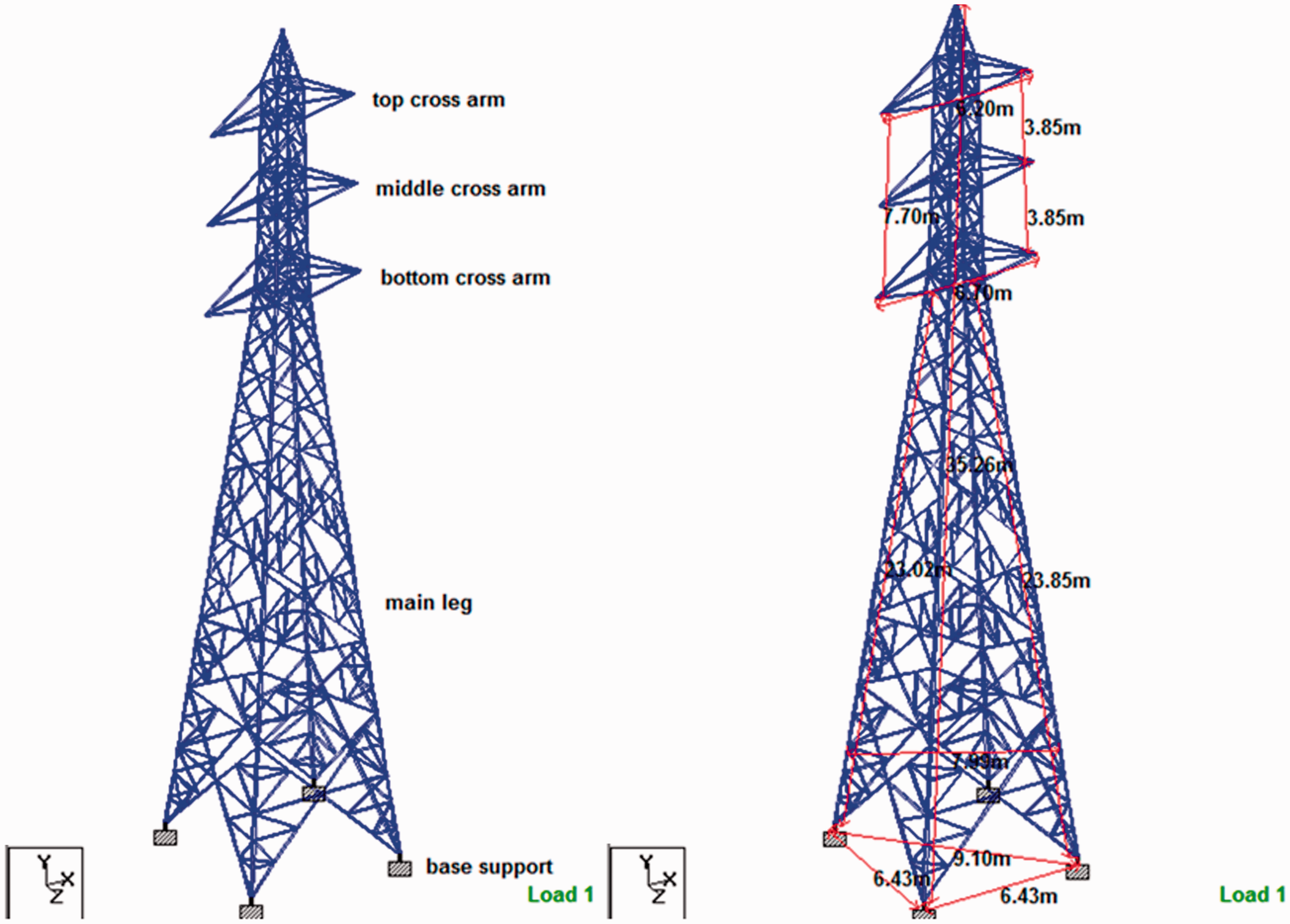
The dimensional configuration of 132 kV GFP composite transmission tower model.
Proposed design parameters for GFP composite transmission tower conducting wire and ground wire.
GFP: glass fibre polyamide; MoE: modulus of elasticity.
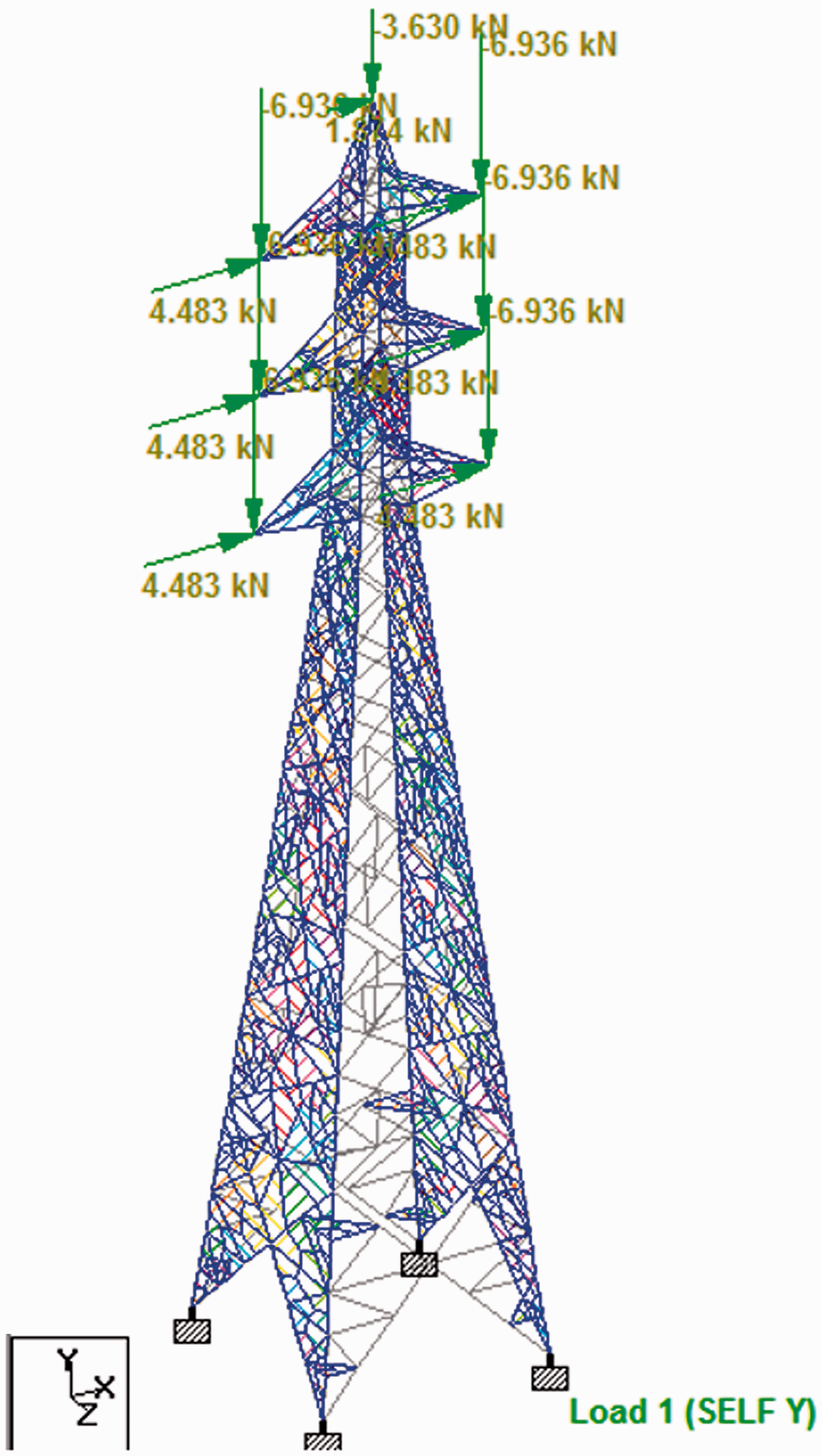
Load applied on the transmission tower model
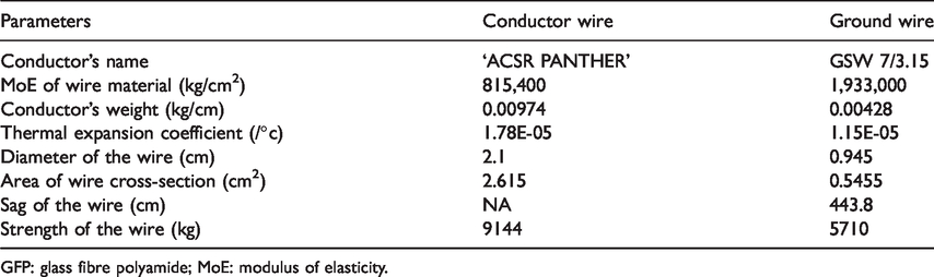
Wind load is one of the most vital loads that act on transmission towers. The estimation of wind load on conductors is found to be 4.48 kN that are converted to point loads and applied at the composite tower model. The estimation of wind force on the ground wire has been found to be 1.87 kN which is converted to point load and applied at the tip of the composite tower model as shown in Figure 3. Due to unbalanced load which is generated from conductor breaking, the composite tower structure is subjected to longitudinal load. 13.76 kN has been estimated to be unbalanced force due to conductor’s breakage as shown in Figure 4. The vertical load consist of weights of insulators, conductors, tower, repairing line man and all other accessories that are attached to transmission towers. The insulators’ weights are generally considered as one of the design parameters in accordance with the industry requirement. The conductors’ weight may also be estimated by multiplying weight per unit length of wire to the wire length, and the tower’s weight is generally assessed by the weight of the material that is utilized for tower structure construction. Subsequently, the ground wire weight has been estimated to be 3.62 kN and the conductors’ weight is evaluated to be 6.94 kN that is applied to the cross arm tips as shown in Figure 3. Wind loads at body of tower have been applied as per the appropriate intensity STAAD pro module shown in Figures 3 and 4. Table 4 presents the detailed calculated loads.
Loading of GFP composite transmission tower model in NC.
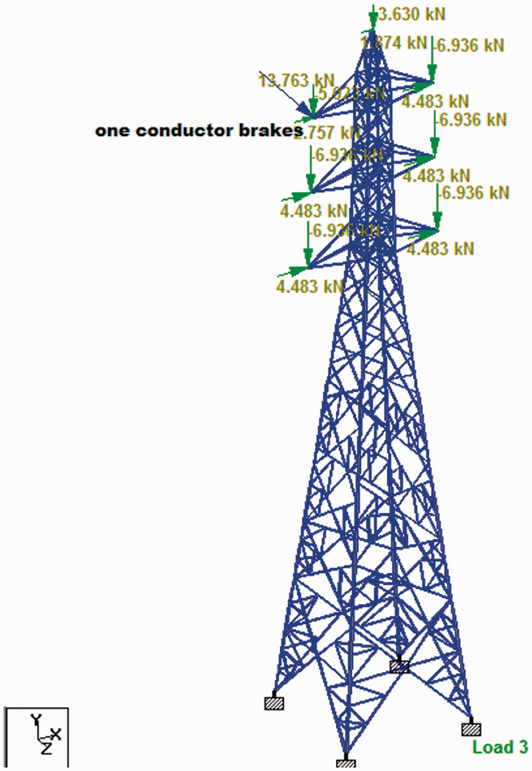
Loading of GFP composite transmission tower model in BWC.
Manually calculated loads for GFP composite transmission tower model under NC and BWC. 20
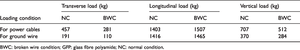
BWC: broken wire condition; GFP: glass fibre polyamide; NC: normal condition.
Result and discussion
Discussion on stability of tower members
Since the transmission tower comprises of many members/components, thus, the overall stability of tower could only be analysed through detailed analysis of members. Failing of one member may lead to the failure of whole structure. The stability of transmission tower is totally dependent on the stability of tower components/members. Hence, detailed analysis of each and every member is required. Each member of the tower is subjected to compression or tension. Yielding of the member is denoted by tension capacity. The elastic or inelastic buckling capacity of tower member is denoted by the compression capacity of the tower member.
To evaluate the stability of tower, maximum stress has to be obtained on the tower members. In case of dynamic analysis, the stress distribution continuously changes but it is fixed in the case of static analysis. Hence the location of maximum stress also changes. So it is difficult to extract the information of maximum stress location in the tower body in the case of dynamic analysis. For static analysis case, at several load conditions, the stresses of maximum compressive/tensile primarily instituted to occur proximate to the tower foot at main bars. Stability of the transmission tower mainly depends on maximum stress occurring on the tower members. Hence for examination of the failure of the composite members, under several wind load condition the model has to be solved.
Analysis of results
The transmission tower model has not been damaged under design loading and typical operating conditions. The tower’s mechanical strength has the feature of resisting bending and it meets the design requirements. The analysis of composite transmission tower model has been performed and analysed the behaviour when the composite tower model is subjected to different loading situations. The maximum stresses and displacement are developed in the tower members when the transmission tower structure has been exposed to normal loading conditions. For static analysis at several load conditions, stresses of maximum compressive or tensile mainly resulted in proximity to the main bars of tower foot. The maximum tensile stress that is detected at proximity to the tower base is 564 MPa, as shown in Figure 5. The tensile stress of GFP composite material is in the range of 400-700 MPa, shown in Table 5. The maximum tensile stress was estimated to occur at the tower foot of main bars that was found to be less than that of the breaking stress of GFP. It is to be mentioned that stress values obtained from the FE analysis may vary from the actual stress occurring at the transmission tower members and this is because (i) in the FEM, the stiffness of the tower may be underestimated and (ii) the complications of modelling the true boundary conditions. It may be stated that the composites are able to endure bearing load of tower that stables the tower structure.
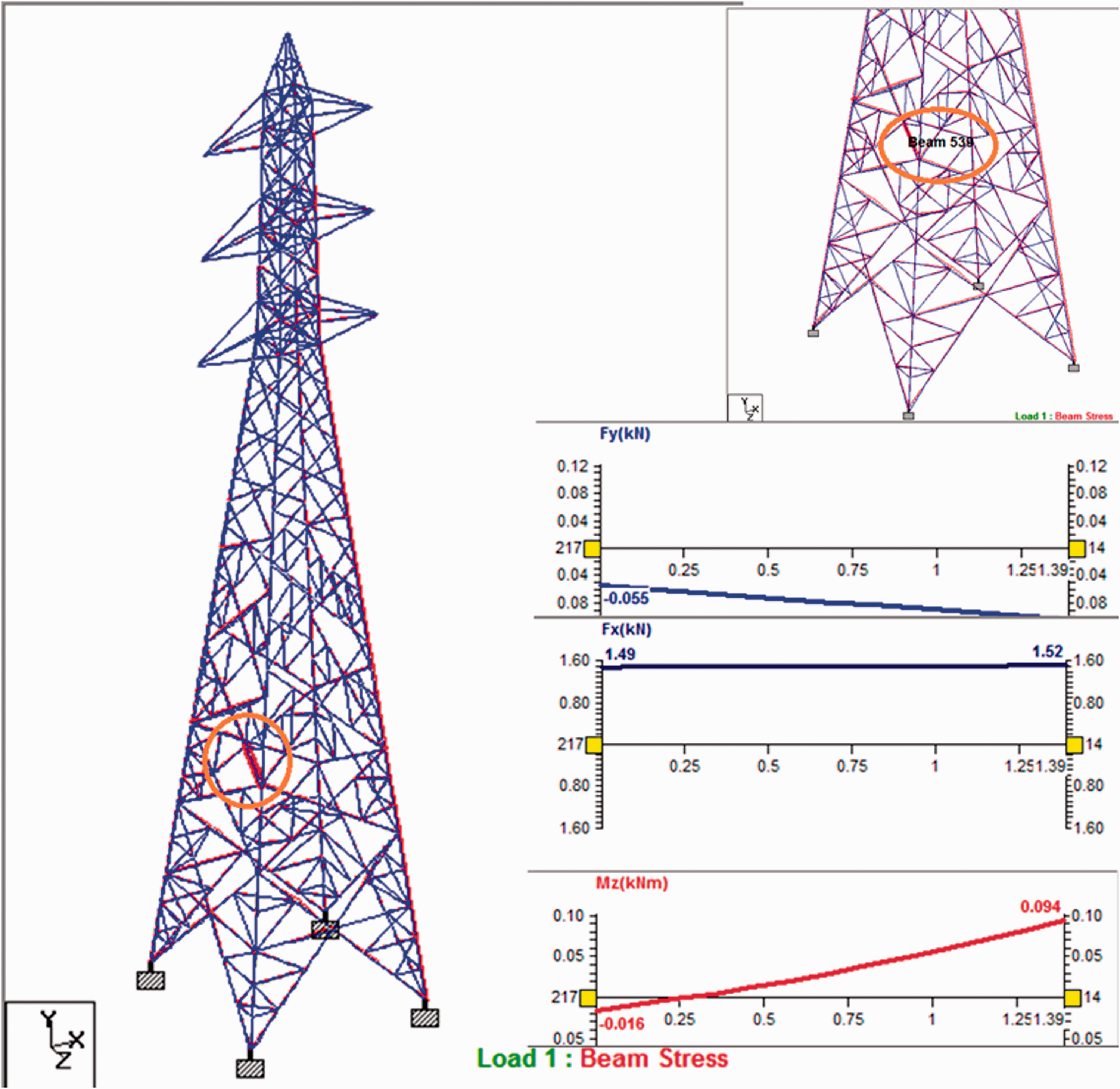
Moment, shear forces of member 539 with NC.
It has been observed from the simulation results that the maximum stress is at the member element 539 of the composite transmission tower model that has been found to be 564 MPa. Hence, for the stability analysis of the tower, the element 539 has been documented to have maximum compressive stress. Figure 5 indicates maximum compressive stress located on the leeward side of the tower foot. The maximum stress was found to be 564 MPa at lower part of the composite tower, whereas the tensile stress of GFP is in between 400 and 700 MPa. Hence, it may also be indicated that a tower is able to operate typically for structural stability. The damage of the whole tower is caused due to bending deformation of the main bar results. Figures 6 and 7 demonstrate the support reaction at normal loading and BWC. The maximum support reaction of 282 kN at support 4 and maximum moment of 4.129 kN m at support 3 have been found in normal loading condition, as shown in Figure 6, whereas the maximum support reaction 313 kN and maximum moment 4.021 kN m have been found at support 4 in BWC, as shown in Figure 7.
Details specifications of GFP composite material for transmission tower.
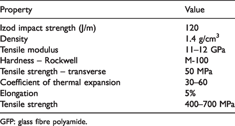
GFP: glass fibre polyamide.
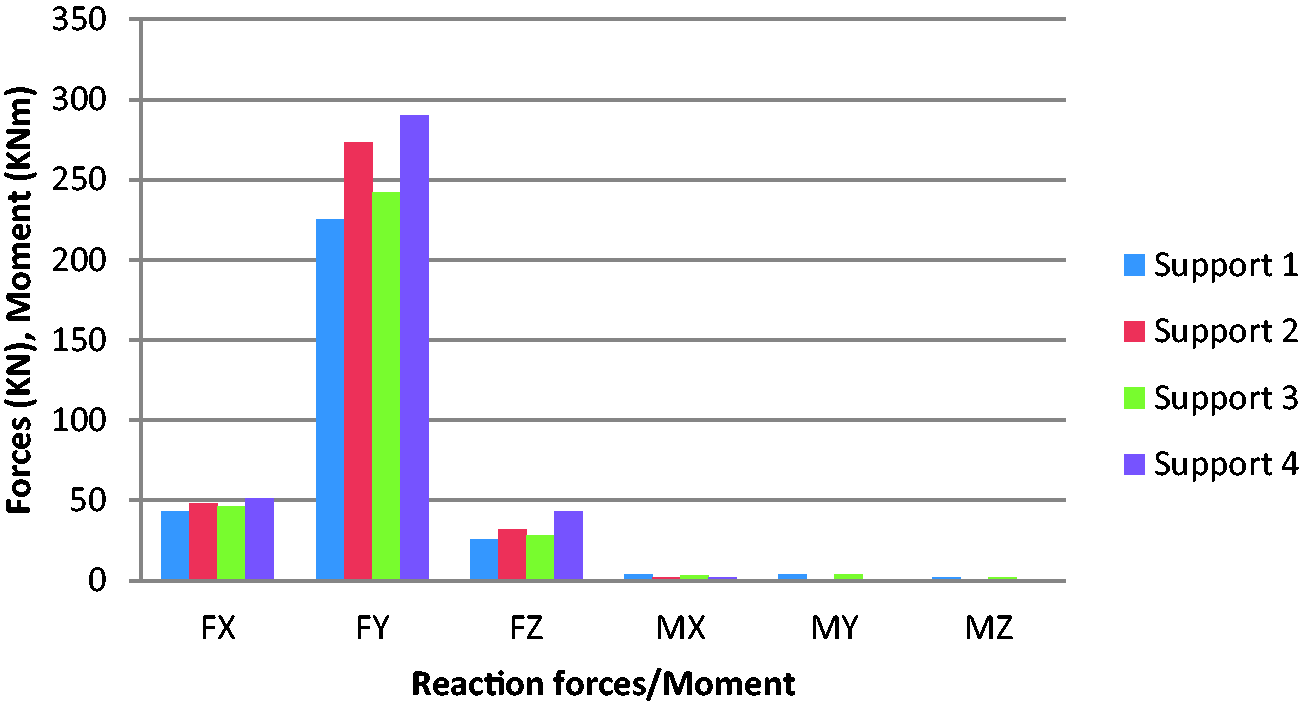
Reaction forces and moment for all four supports with NC.
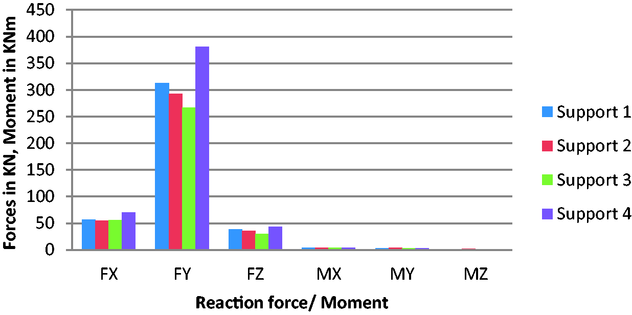
Variation of reaction forces/moment at four supports with BWC.
The displacement of tower has been found to be more at the structure’s upper part at normal load and BWC, as shown in Figures 8 and 9. Tower deflection under normal loading condition has been found to be maximum at the top which is less than 1% of height of the tower, which meets the design requirements, as shown in Figure 8. Tower deflection under BWC has also been found to be maximum at the top which is less than 1% of height of the tower, which also meets the design requirements, as shown in Figure 9. Li et al. 4 suggested that the tower deflection under normal loading condition and BWC should be around 1% of tower body height. According to the Indian design code, the maximum node displacement of the composite tower meets the requirements. 33 However, the deflection of steel lattice transmission is less than the composite tower, reported in the literature. In the practical operation, the influence of deflection on the transmission line operation needs to be verified further. In this study, it has also been identified that for tower’s stability analysis, results of simulation have been used at altered wind loads. The maximum stresses obtained at normal loading and BWC is shown in Figures 10 and 11. The maximum compressive stress of 467 MPa and maximum tensile stress of 415 MPa have been found in normal loading condition, as shown in Figure 10, whereas the maximum compressive stress of 499 MPa and maximum tensile stress of 564 MPa have been found in BWC, as shown in Figure 11. The maximum stress of composite tower has been found to be 564 MPa, which is less than the GFP strength values. Vladimir et al. 29 have studied the applicability of GFRP as alternative material for transmission tower where they concluded that the induced maximum stress value under different loading condition in the transmission tower member must be less than the strength value of the GFRP composite material. As the GFP strength values meet the design requirements, it is safe for transmission tower as per design code. 33
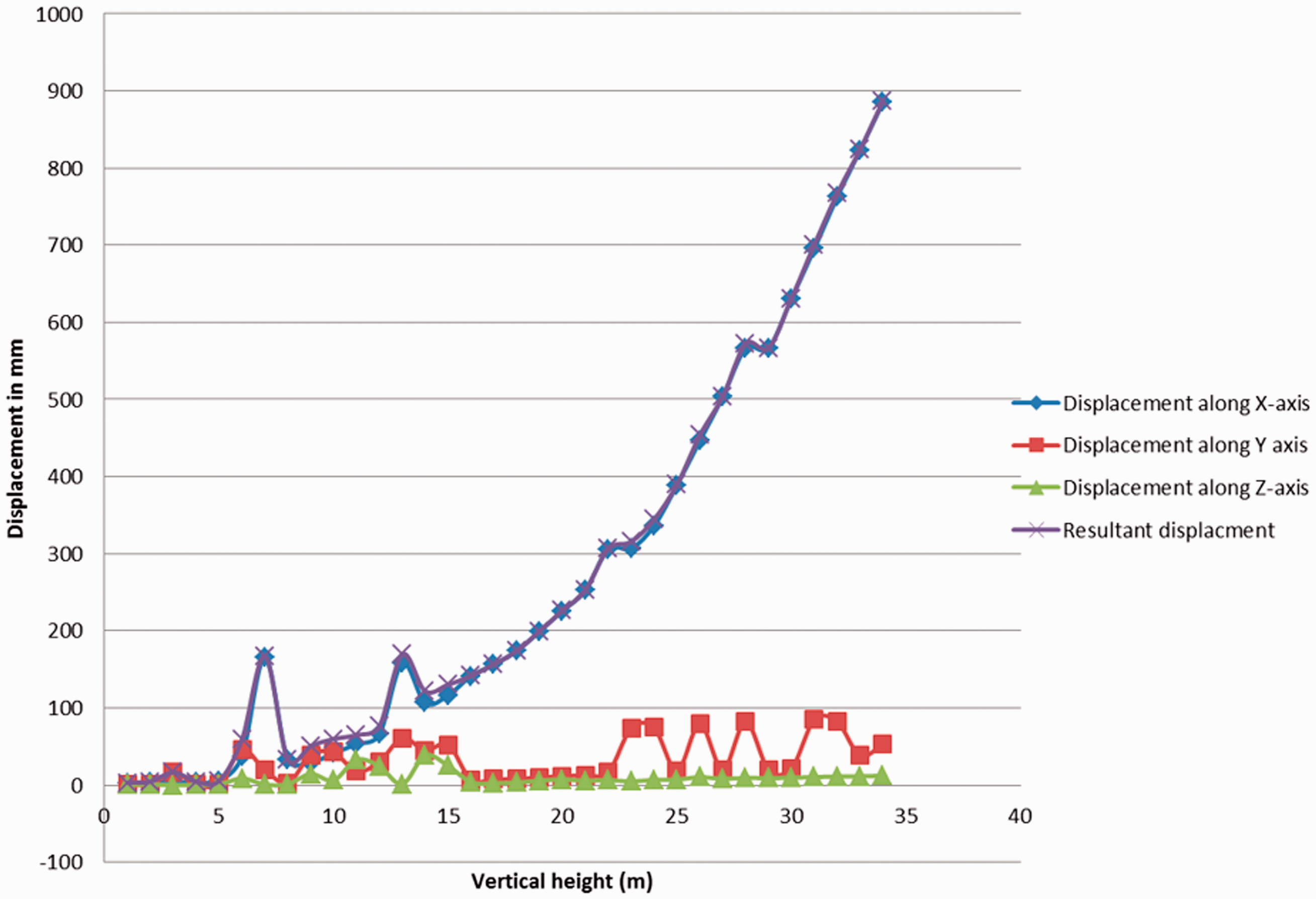
Vertical height versus displacement with normal loading condition.
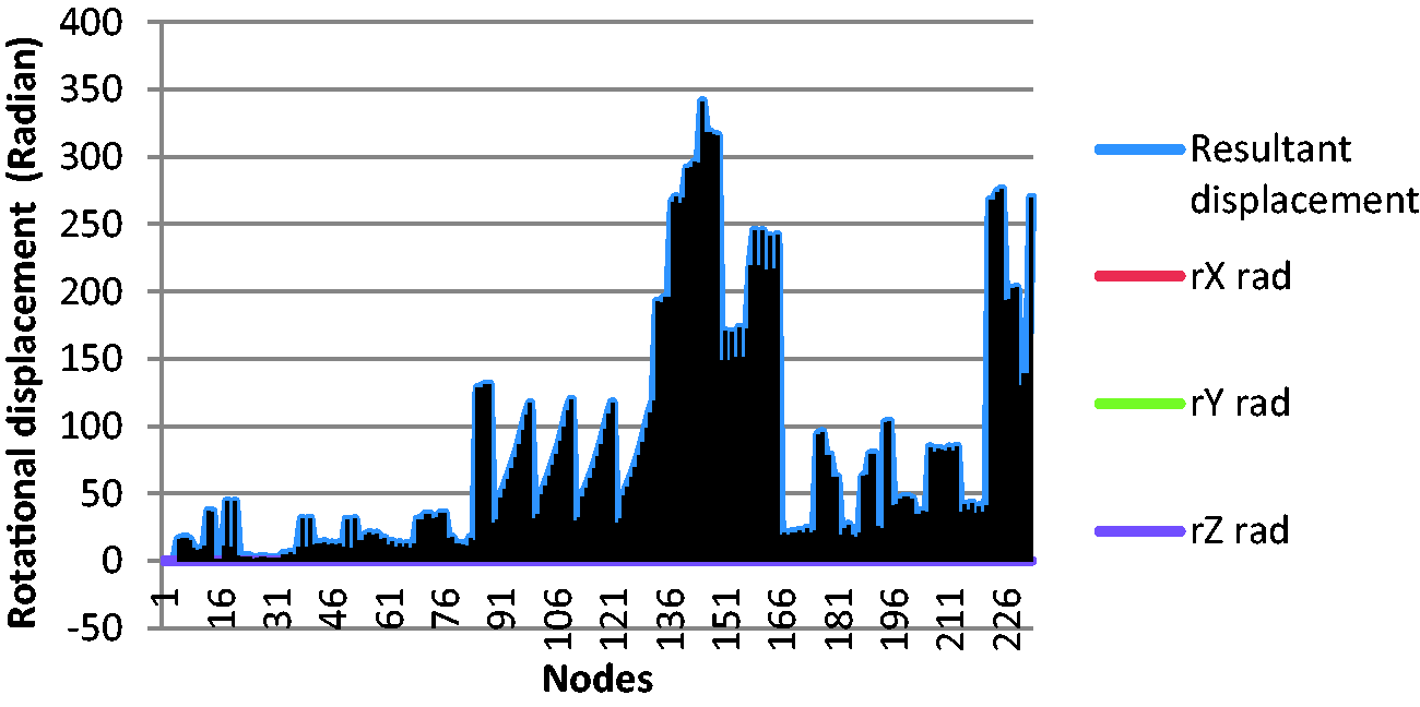
Nodal displacement of GFP composite transmission tower model in BWC.
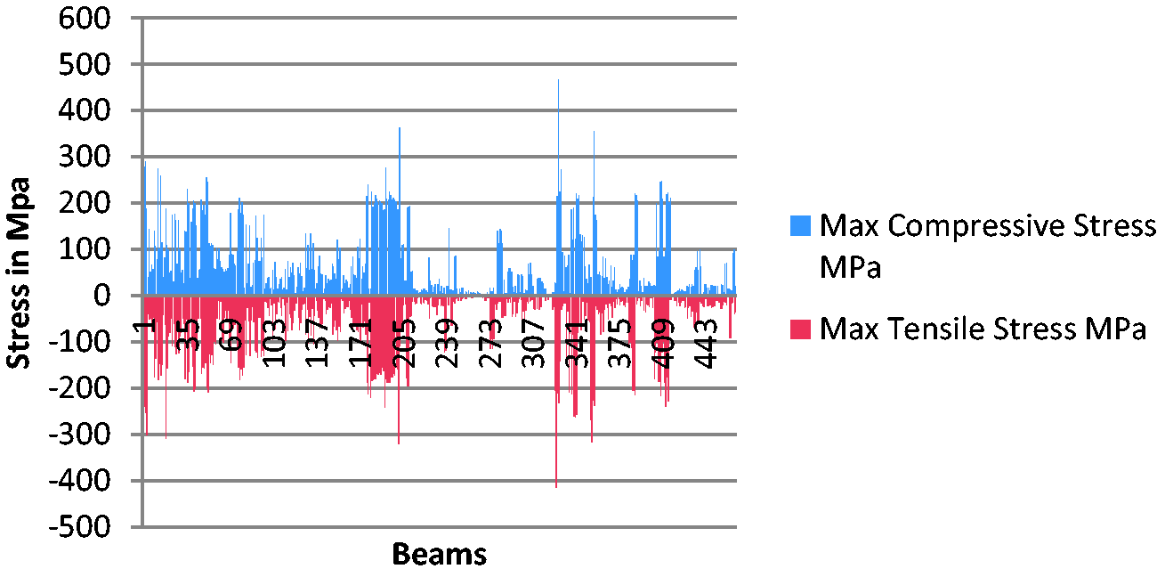
Maximum tensile and maximum compressive stress of GFP composite tower members in NC.
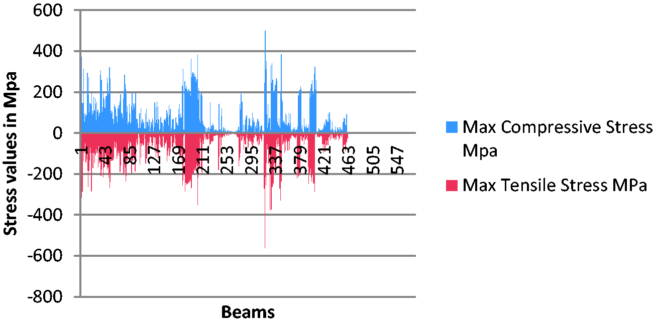
Maximum tensile and maximum compressive stress of GFP composite tower members in BWC.
Conclusions
In the present study, the performance evaluation of GFP composite transmission tower using standard STAAD software has been done. The key aim of the current research is to test the structural performance and stability considering composite materials for lattice transmission tower structure. A tower model has been built in FE tool STAAD Pro as per IS design code. The static wind loads have been applied to the FE model, and simulated the stress distribution. The BWC (if one conductor breaks or earth wire breaks) has been innovatively considered. The results show that the longitudinal stress of tower member is much less than the longitudinal stress of GFP composite material. In the static analysis case, under several loading environments, the maximum compressive and/or tensile stresses occurred mainly at main bars of the tower foot. The maximum tensile stress of the transmission tower member (564 MPa) was observed near to the tower base. For GFP, the tensile stress is in between 400 and 700 MPa. The maximum tensile stress found in the simulated stress model is less than that of the breaking stress of the GFP at different load conditions. Meeting the design requirements of design strength, the maximum stress of the composite tower (564 MPa) has been found to be less than the GFP strength values. Hence, it can be concluded that GFP is able to withstand all loading related to transmission tower in practical field. The GFP is found to be the most competent composite materials for the transmission tower as alternative material as per as the good structural performance and the stability is concerned.
Footnotes
Declaration of conflicting interests
The author(s) declared no potential conflicts of interest with respect to the research, authorship, and/or publication of this article.
Funding
The author(s) disclosed receipt of the following financial support for the research, authorship, and/or publication of this article: The authors would like to thank MHRD, India for the funding.