
Abstract
Market demands for lightweight and lower cost products drive manufacturers to improve current product portfolios. In the case of electronic devices, the most significant weight originates from the enclosure, traditionally in steel or aluminum, that ensures excellent mechanical and electromagnetic shielding performance. The use of thermoplastics filled with electrically conductive fibers, such as carbon or stainless steel, was investigated as a lightweight and cost-effective alternative to steel sheet for creating electromagnetic interference (EMI) shielding enclosures for electronic devices. This paper presents an EMI shielding analysis workflow for the development of plastic enclosures for an electronic device. The workflow starts by measuring the fiber-reinforced thermoplastic compounds shielding effectiveness (SE) with an experimental method in the 30 MHz–3 GHz frequency band. This analysis helps to filter a vast list of materials with a wide range of shielding performance, 20–100 dB, and allows to obtain empirical data for the second phase of the workflow, computer simulations. Simulations with experimentally adjusted material properties were used to validate the design concept of an enclosure in its early development phase. Results from this study showed that the selected material has better EMI SE performance than a steel sheet venting grid.
Keywords
Introduction
Current trends for digitalization, IoT, and human-machine interface systems lead to the proliferation of electronic devices and radio-frequency systems, such as multimedia, radio, wireless networks, GPS navigation, and several sensors. These electronic devices usually are enclosed by a metallic housing, which provides structural support to electronic components, enables heat management, and act as a shield to EM/RF interferences. However, the interest for lightweight and more complex and efficient products is encouraging manufacturers to follow a transition from metallic to plastic materials.
The use of engineering plastic composites allows components weight reduction, improved corrosion resistance, and enables flexible design and part consolidation allowing lower cost production. However, these plastic composites have lower conductivity when compared to metals making the study and optimization of their properties an important subject in order to achieve an adequate shielding effectiveness (SE) and electromagnetic compatibility (EMC) compliance for the electronic device. Hence, plastic composites anisotropic characteristics scale up their electrical properties and shielding complexity, subject that deserve intensive investigation.
This paper presents a workflow that can be used in the early design phase for an electronic device enclosure made with plastic materials. Such workflow can provide valuable data required by engineers to advance in the product development phase.
The first stage of the workflow consists of the EMI SE measurement of several commercially available polymer composites with different filler types (carbon fibers (CF), long carbon fibers (LCF), and stainless steel fibers (SSF)) and different concentrations. The SE performance will validate the potential of use of the composite material to produce a specific electronic enclosure with a minimum shielding of 60 dB, established limit for the bulk material.
The second stage of the workflow consists of a computer simulation methodology to understand the shielding performance of the enclosure critical design features (e.g., vent apertures) and achieve an early EMC pre-compliance approval. The shielding lower limit for these critical features was established as 40 dB.
Literature review
An electronic device is considered electromagnetic compatible if it operates properly in its intended electromagnetic environment and does not interfere with other devices or itself and if it is not susceptible to radiation from other devices.1,2 Therefore, all electronics must be protected from EMI by means of an enclosure which provides mechanical support and EM shielding by forming a Faraday cage.2–4 A good shielding should prevent both incoming and outgoing EMI by cutting the interference signal pathway with an EM impermeable material (shield), preventing noise, malfunction, or even electric circuits and components burn.1,2,5
The efficiency of a material to attenuate EMI radiation is designated as SE and is an EM field ratio between the source and the receptor that can quantify the attenuation of the waves propagation through the material or apertures of an enclosure.1,2,6,7 SE is expressed in decibel (dB), and the common requirement for commercial electronics is the range from 40 to 60 dB3,4, though an SE of 30 dB (99.9% attenuation) is also considered an adequate level of shielding for many applications.8,9
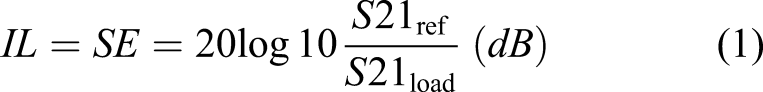
The efficiency of a shield can be measured against near-field or far-field sources by free-space methods or closed transmission line methods, and each of them has advantages and limitations.1,2,5 Focusing on measurements for normally incident plane waves (far-field radiation), the most used technique is based on the procedure according to ASTM D4935 standard test method for “Measuring the Electromagnetic Shielding Effectiveness of Planar Materials”. This procedure applies to the measurement of the SE of planar materials under normal incident plane-wave conditions according to the transverse electromagnetic wave propagation mode.7,10–12 This procedure is based on insertion loss (IL) methods between an EM signal generator and a receiver and can be conveniently performed using a vector network analyzer. The resulting SE is expressed by the ratio of the transmission scattering parameters S21ref and S21load11,12 Schematic of shielding mechanisms.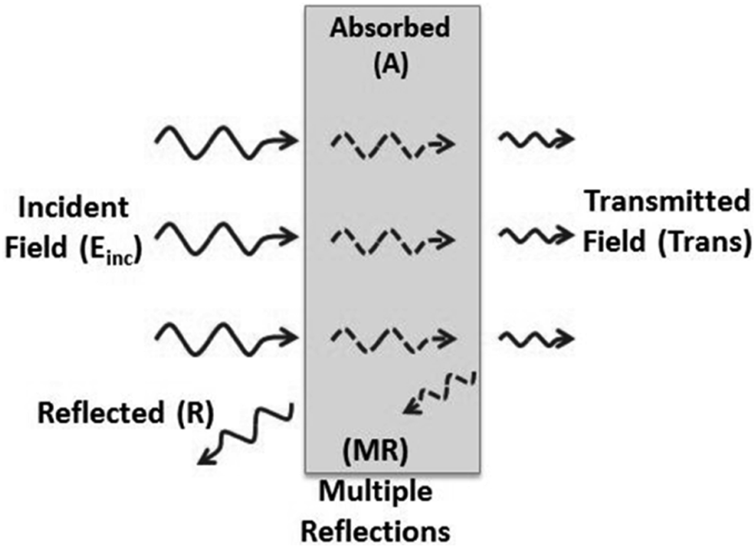
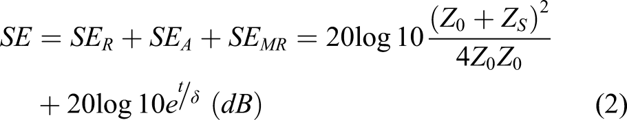
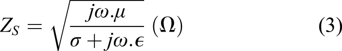
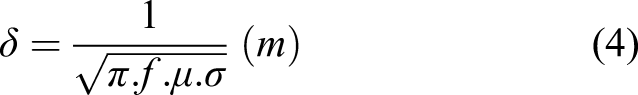
This model describes EMI SE as a sum of reflection (R), absorption (A) and multiple internal reflections (MR), equation (2), when the EM waves interact with an infinite large homogeneous shielding material, in particular a good conductor shield. Reflection loss (SER) is the primary mechanism of shielding, and it is related to the mismatch impedance, from the material free charges carriers, between the shield’s surface and propagating wave at free space (Z0 ≈ 377 Ω). Absorption loss (SEA) is the secondary mechanism of shielding and exponentially increase with the shield thickness. It happens due to magnetization and electric polarization processes in the medium. The third mechanism of shielding is the multiple internal reflections from the adjacent conducting layers. For practical purposes, this mechanism can be neglected when SEA > 10 dB.15,17,18 This theory is used to characterize the SE of materials at plane waves (far-field region) and settles essentially in three characteristics of the shield material: intrinsic impedance (Zs), skin-depth (δ), and thickness (t).2,15 The electrical conductivity (σ) of the material is the most important property for obtaining a proper shielding, being that SE is directly proportional to it
Polymer composites with conductive fillers are attractive materials for EMI shielding due to their low density and easy processability (e.g., injection molding) that allows the production of more complex and lightweight enclosures without seams, which are preferable features for EM radiation leakage and SE dropping. 13 The use of injection molding technology for conductive polymer composites electronic enclosure enables industrial production with reduced costs.
Researchers have been studying SE of polymer composites for different matrix and conductive fillers obtaining a wide range of shielding performance. Preferable fillers used for this application are carbon fibers, carbon nanotubes/fibers, nickel coated carbon fibers, stainless steel fibers, and metallic particles. Due to their ferromagnetic nature, stainless steel and nickel fillers allow higher EM absorption resulting in increased composite SE. Therefore, polymer composites with stainless steel fibers or nickel coated carbon fibers have better shielding effectiveness.4,7,14,17,27–29
The analysis of the shielding performance of enclosure design and its critical features (e.g., seams and apertures) performance is one important aspect for an early EMC pre-compliance and it can be attained by resorting to computer simulation methodologies. These simulations use computational electromagnetics software, which are numerical tools specifically dedicated for solving electrodynamic equations and simulate EM/RF environments and problems. Such tools have been used to describe many EMI problems in circuits and components and help in their redesign for attaining EMC compliance. 30 Such numerical tools allow the simulation of SE for different kind of materials and structures to prevent EMI or EMS. However, simulated materials are usually metals and have isotropic behavior with well-known properties which can be accurately represented in virtual models. Shielding for more complex materials (e.g., composites) have been reported.18,31–37 However, these researchers focus only on organized filler structures or multilayer systems.
The authors of this paper intend to add more information to the underexplored field of computational electromagnetics of polymeric materials by introducing a two-step workflow for the EM shielding analysis by executing simulations with experimentally adjusted material properties.
Work methodology
Materials
Several commercial fiber-reinforced thermoplastic compounds from different suppliers were identified and tested during this project in order to characterize their SE and check their applicability to an electronic enclosure which required a minimum shielding level of 40–60 dB.
Materials selection process was essentially based on their electrical resistivity since SE is related to that property. However, aspects such as stiffness, thermal stability, processability (injection molding), and costs were also considered.
Reinforced thermoplastic compounds with respective electrical properties.
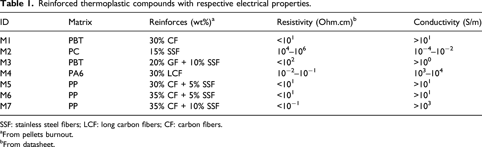
SSF: stainless steel fibers; LCF: long carbon fibers; CF: carbon fibers.
aFrom pellets burnout.
bFrom datasheet.
Samples preparation
Solid flat disk-shaped samples with nominal thickness of 2 mm and diameter of 60 mm were produced for each selected material. Disks were produced by injection molding and following the recommended guidelines from the respective material datasheet. For each material was produced 5 “Load” samples and 1 “Reference” sample as specified in Figure 2. Sample holes and toroid shape cut in “Reference” specimen were made in a milling machine. Samples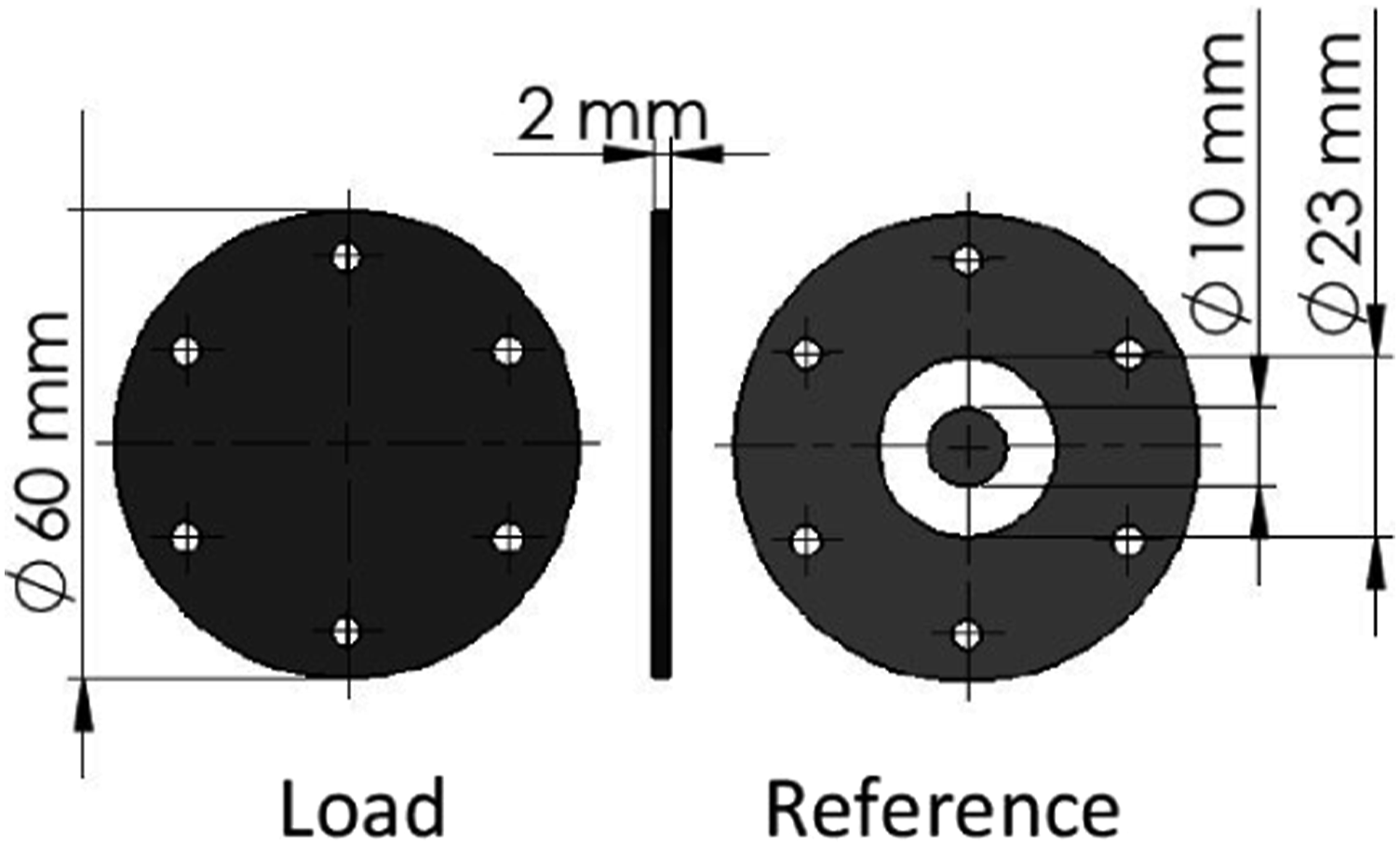
SE experimental apparatus
Shielding measurements were performed by means of a test procedure based on the withdraw ASTM D 4935 standard test method. Equipment setup is shown in Figure 3, and it consists in using a flanged coaxial sample holder (FCSH) which is a special made coaxial airline that allows the propagation of EM waves and sample support in between. FCSH is connected to a vector network analyzer (VNA ZVL3 from Rohde & Schwarz) which acts both as signal generator and receiver. Connection to VNA is made through two 10 dB and 50 Ω attenuators, placed at the edges of the sample holder and attached to the coaxial cables. The 50 Ω attenuators are used at the end of the specimen holder to improve the impedance matching. Experimental apparatus schematic.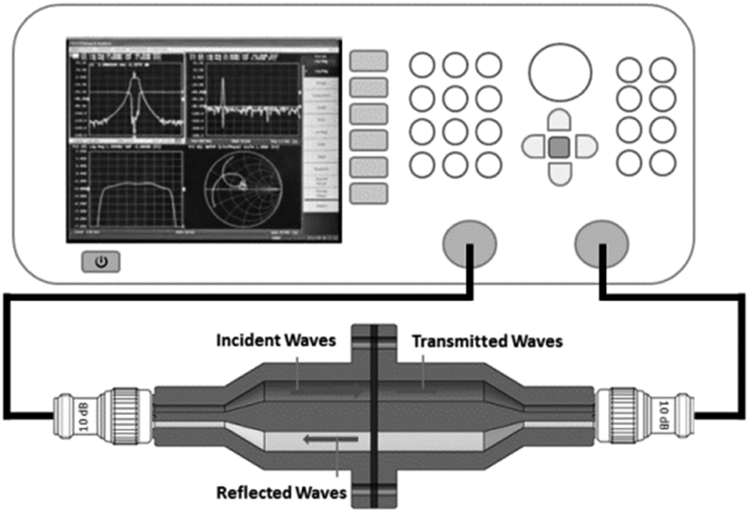
Flanged coaxial sample holder is an enlarged coaxial transmission line, in which inner and outer conductors (made of Brass alloy) were designed and manufactured in our laboratory to support the 60 mm diameter samples maintaining a characteristic impedance of 50 ± 0.28 Ω throughout the entire length of the holder and a theoretical cutoff frequency of 5.78 GHz. Inner and outer conductor’s concentricity is supported by 4 O-rings (2 in each flange) of non-conductive material (Nylon) that has negligible signal attenuation. Samples are placed between the two sections of the sample holder and tightened together by 6 non-conductive screws (Nylon).
Shielding effectiveness was measured at the frequency range between 30 MHz and 3 GHz, radio-frequency spectrum, and it was determined by the ratio between reference and load samples transmission scattering coefficients (S21) as expressed in equation (1).
SE computational simulation
Shielding effectiveness simulations were performed in CST Microwave Studio Suite®, which is a commercial software specialized in the 3D simulation of EM waves propagation of high frequency components. Simulations were executed by means of the transient solver which is based on the Finite Integration Technique (FIT) and use a hexahedral mesh grid with a perfect boundary approximation.
Simulation workflow was divided in two sequential analyses that used different geometric models.
Plastic compounds SE simulation
The first analysis used a 3D model of the experimental test fixture (Figure 4) and it was used to perform a numerical approach of the material SE experimental results in the frequency range of 30 MHz and 3 GHz. Just like in the experimental procedure, SE was obtained by the transmission coefficient (S21) between two 50 Ω waveguide ports placed at the edges of the 3D model. 3D model of experimental test fixture used in simulation.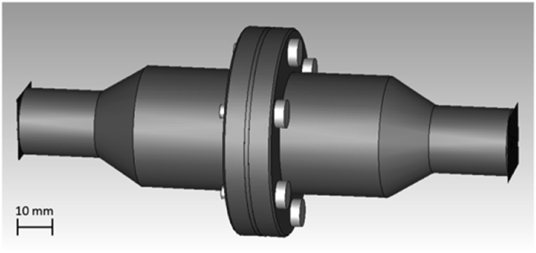
Complex electrical properties (σ, ε, and μ) as functions of frequency are necessary to perform an accurate simulation of these heterogeneous compounds. However, material supplier’s datasheets are almost limited only to DC electrical resistivity data which is insufficient information for an accurate material simulation. Therefore, an assumption was made considering a homogeneous and isotropic material with permittivity and permeability equal to vacuum (εr = 1 and μr = 1) and constant electrical conductivity. Conductivity values were estimated by incrementally increasing it until the simulated SE matched the experimental SE for the corresponding material. The process for fitting the conductivity was executed for the complete frequency band and not for each frequency step and took many iterations to meet an adjusted value. Fortunately, the FIT solver has some characteristics to accelerate the computational process, allowing to run all simulations in a couple of days.
Enclosure features simulation
The second part of the simulation workflow has the objective to compute the SE of the enclosure critical areas for EMI, such as apertures for ventilation. For this study, several rectangular waveguides 3D models (Figure 5) were used to cover a wide range of the radio-frequency spectrum (L, S, and C band). Waveguides 3D models were created based on the standardized waveguide to coaxial adapters (WR650, WR510, WR430, WR340, and WR187) which operate at a specific frequency range for normally incident waves with the transverse electric (TE10) propagation mode. SE was also obtained by the S21 coefficient between the two waveguide ports placed at the edges of the 3D model. Waveguides 3D models for aperture SE simulation.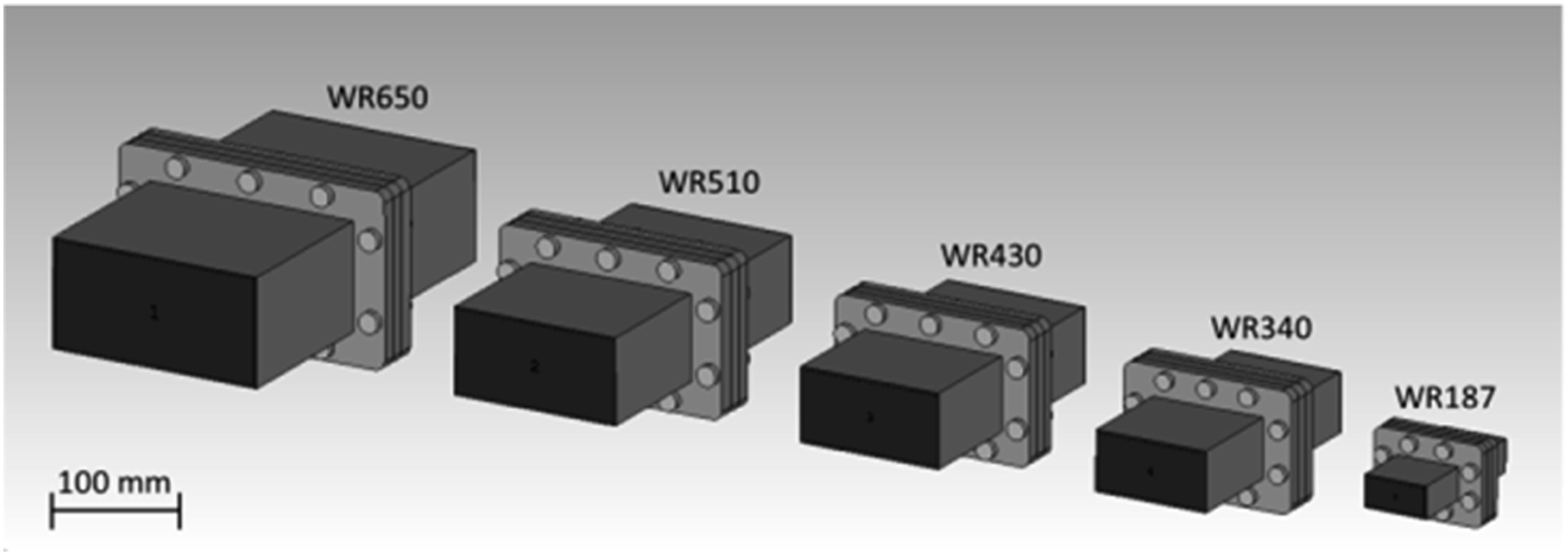
Samples placed inside these waveguides are shown in Figure 6. These samples are a representation of an enclosure air ventilation grid, made by a 5 x 11 array of 3 mm diameter holes with 4 mm spacing between hole’s center. This analysis was made for the plastic compound with best SE performance with 2 mm thickness in comparison with a typical stainless steel (σ = 6.9 x 10⁶ S/m) shield with 0.8 mm thickness. Samples geometry placed inside respective waveguide.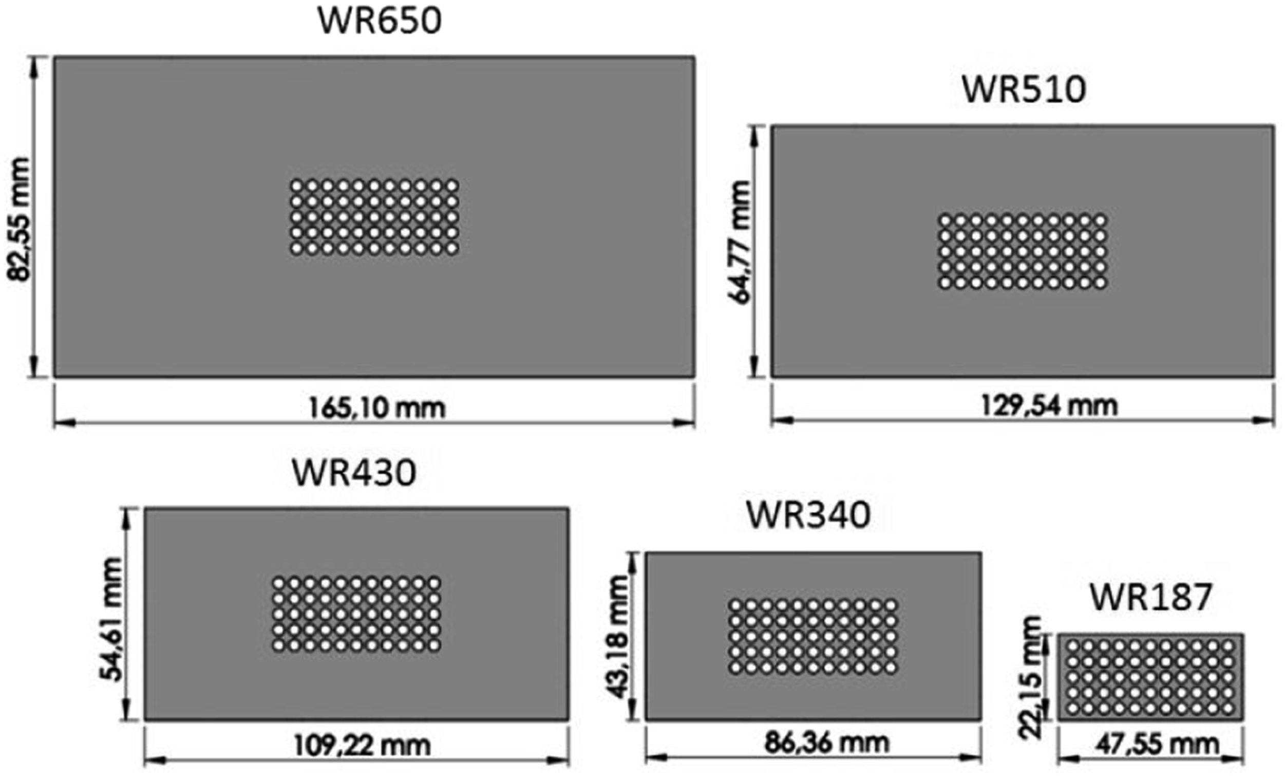
Results and discussion
Experimental results
As it was to be expected, the selected plastic compounds evidenced different shielding characteristics, showing wide orders of magnitude of its attenuation levels that can reach from 20 dB up to 100 dB, depending on the frequency of interest and the filler content. The EMI SE representative curves for the tested materials are shown in Figure 7. EMI SE for tested materials.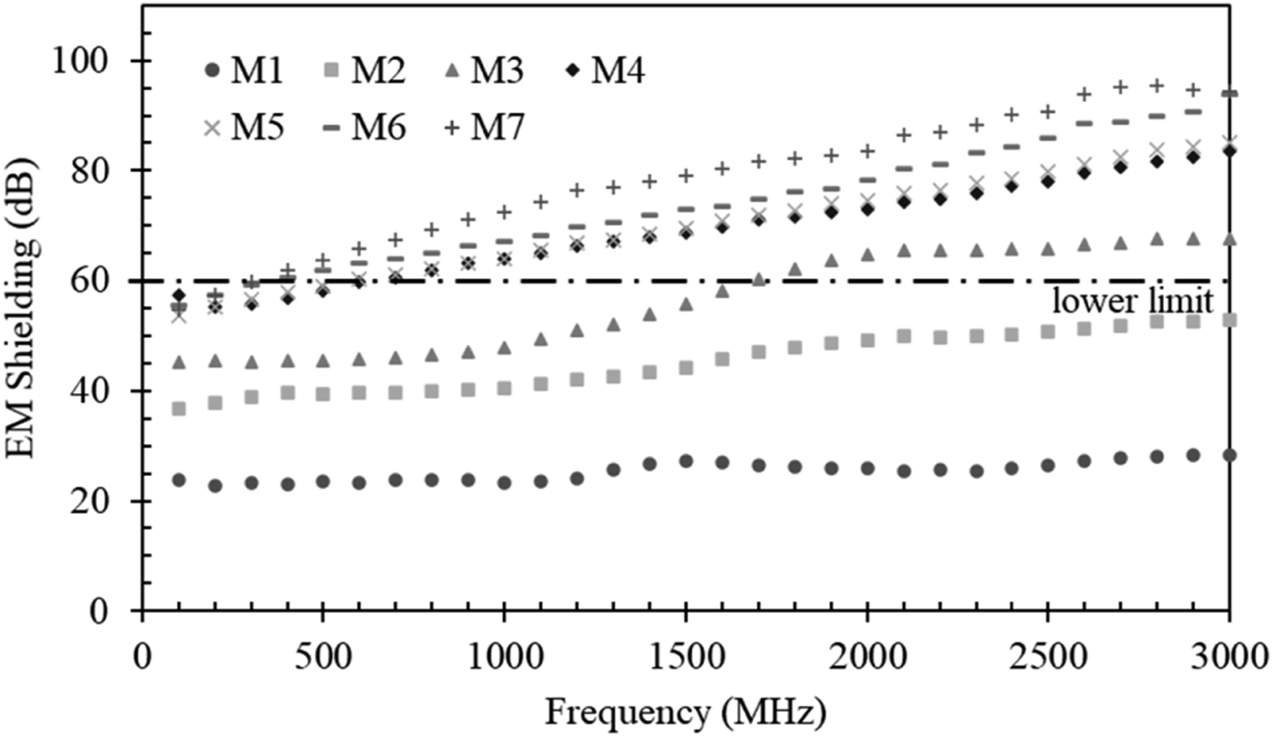
From this analysis, it was possible to select suitable materials to be used for the enclosure. Those materials are M4, M5, M6, and M7, being M6 and M7 the most promising as they achieve shielding above 60 dB in almost all the frequency band.
This wide range of SE is mainly affected by the conductive fillers’ (fibers) electrical properties and their concentration, dimension, and orientation inside polymeric matrix. These characteristics affect the specimen’s bulk properties, resulting in different SE levels. Depending on the fiber’s characteristics, there is an evident increase of shielding with the increase of fiber concentration. Also, knowing that injection molding conditions affect fiber length and dispersion in the sample, we can expect that SE can be increased through processing optimization.
The use of SSF enabled better results than short carbon fibers (CF) even for compounds with lower SSF weight concentration, as can be seen comparing M1 with M2 and M3. This is due to the fact that SSF have greater conductivity than CF and have ferromagnetic characteristics which enables greater EM absorption.
Long carbon fibers have better SE than short carbon fibers as can be seen comparing M1 with M4 samples. Compounds with LCFs reinforces can even achieve better shielding than compounds with SSF. The use of LCFs shows great promise for the development of a plastic enclosure; since, besides shielding efficiency, they also enable greater stiffness to weight ratio than SSF compounds.
Best shielding results were achieved with compounds made with the combination of CF and SSF, being M7 compound the best performer.
Simulation results
As previously mentioned, simulations were executed by considering approximations to the experimental SE results by systematically changing the electrical conductivity of an isotropic sample. This procedure was adopted since there was insufficient material properties information to use as inputs.
It was verified that conductivity values of 50, 250, 500, 950, 1100, and 1400 S/m enable an approximation to experimental SE for M1, M2, M3, M4, M5, M6, and M7, respectively. Both experimental SE and respective simulation representative are shown in Figure 8. Experimental and Simulated compounds SE.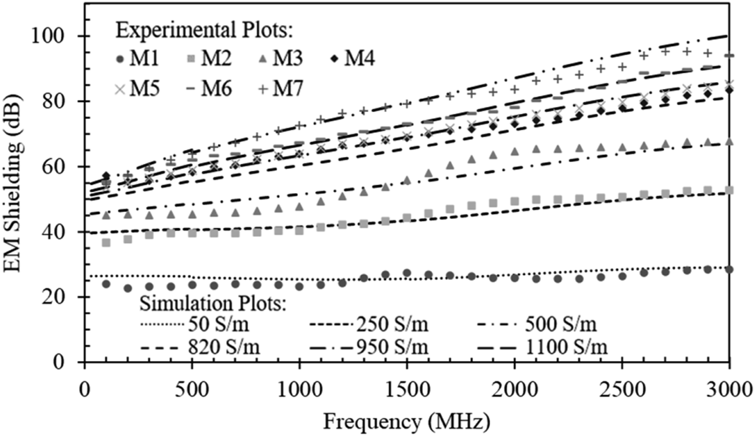
As can be observed, electrical conductivity used for simulation does not correspond to the inaccurate DC resistivity provided by material suppliers. SE is proportional to material AC conductance, which is affected by complex electrical properties (ε and μ) in the frequency of interest. Therefore, it is important to characterize those properties in order to perform an accurate simulation.
Considering the representative electrical conductivity determined in the first simulation model, the second step for simulation of the enclosure was the SE of zones with apertures for air ventilation. This simulation was only executed for the material with better SE (M7) and compared with a typical 0.8 mm thick steel shield, obtaining the results expressed in Figure 9. SE simulated for M7 and steel samples w/t hole arrays.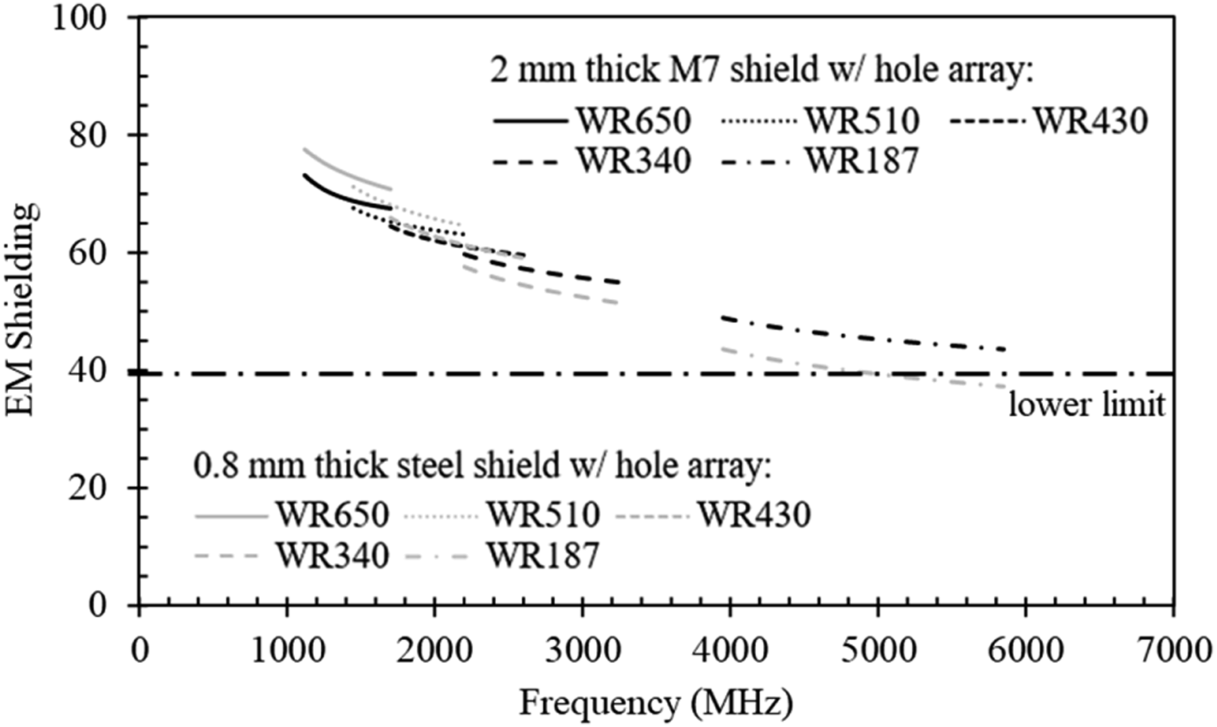
It was detected that SE decreases with frequency increase due to holes becoming electrically large for the EM wavelength, enabling their propagation through the apertures.
At lower frequencies, where reflection effect is higher, steel shield samples have a slightly better performance than shields with M7 compound. However, at higher frequencies M7 samples can achieve better shielding than steel samples. This effect results from the thickness increase from 0.8 mm to 2 mm, making a waveguide effect for the EM waves, which results in lower propagation through apertures.
This simulation presents a good indicator that M7 compound can be used to replace steel enclosures for an electronic device in order to develop a lightweight solution. However, a validation of this model is required through experimental tests.
Conclusions
This paper presents a workflow based on an experimental method followed by computational simulations to evaluate the EM shielding performance of polymeric compounds and its comparison to stainless steel. Results obtained showed that M7 compound meets all the requirements established for an electronic device enclosure. Furthermore, at higher frequencies, M7 compound has better shielding than a similar steel venting grid.
The adopted methodology helped in the selection of a plastic material and helped in the design process for some geometrical features of the enclosure. Results from this process demonstrate that the M7 compound could be used to produce a lightweight enclosure replacing stainless steel. This assumption is valid for the EMC scope and additional studies regarding the thermomechanical performance need to be done to validate the proposal for a plastic enclosure.
The EM shielding properties of several plastic composites was tested by an experimental method and the obtained results showed that these materials can have a wide range of magnitude that can reach from 20 dB up to 100 dB. This characteristic depends on the type of conductive reinforcement, concentration, length, and orientation on the material sample. A combination of CF and SSF reinforcements showed better shielding performance, achieving SE values above 60 dB in almost all the tested frequency range. However, a material filled with LCF showed similar performance making it an interesting material to be used for an enclosure with higher stiffness and even lower weight.
Footnotes
Acknowledgments
Present work was achieved in a co-promotion project between University of Minho and Bosch Car Multimedia Portugal and partially financed by the Portuguese Incentive System for Research and Technological Development, as project no 36265/2013 (Project HMIExcel). The authors acknowledge the support from all entities committed to the project.
Declaration of conflicting interests
The author(s) declared no potential conflicts of interest with respect to the research, authorship, and/or publication of this article.
Funding
The author(s) disclosed receipt of the following financial support for the research, authorship, and/or publication of this article: This study was supported by Portugal Incentive System for Research and Technological Development, Project no 36265/2013.