
Abstract
Gradient distribution of vascular structure made the bamboo wall structure so effective which improved the load-bearing capacity of such bio-mimicked energy absorption structures and modify the crush behavior of thin-walled composite tubes. In this research, the influence of the layering design and stacking sequence on the crush behavior, failure mechanism and absorbed energy of bamboo-inspired GFRP composite tubes is assessed experimentally and numerically. Quasi-static compression tests were conducted to explore seven permutations of Coarse Woven (CW), Fine Woven (FW), and Unidirectional (UD) E/glass fiber sheets, taking into account the longitudinal vascular bundles strengthened by organic matrix. Samples were fabricated employing a modified hand laying up method by using mechanical pressure to obtain better surface finishing and interlaminar adhesion compared to conventional hand layering up methods. To evaluate the corresponding crashworthiness parameters and characterize the crushing behavior of composite tubes, quasi-static axial compressive loading was done. The numerical simulations were validated versus experiments by a commercial finite element (FE) LS-DYNA integrating material model 54. The predicted load-displacement curves and failure mechanisms of FE analysis demonstrate acceptable correlations with visual observations during experimentation. Furthermore, the parametric numerical was performed to examine the effect of different distributions of vascular bundles. The FE analysis results revealed that the crushing behavior of bio-inspired composite tubes depended substantially on layering configuration and the stacking sequence design. The outcomes showed that the combination of woven and unidirectional fibers, respectively, located in the inner layer and hoop direction provide the optimal layering configuration design in terms of crush length efficiency, crush load efficiency, Specific energy absorption, stable progressive crushing, and better manufacturing quality.
Keywords
Introduction
The use of energy absorbing components in a broad range of applications, for example, the automotive, aerospace, building, shipping, oil and gas industries has served them as the major structural elements for protection against crashing. To improve the crashworthiness without excessive weight, E-glass composite materials with amazing specific energy absorption (SEA) are exceptionally appealing. They offer lightweight crashworthy structures, unlike the metallic materials general use.1–3 Extensive testing on different kinds of GFRP circular composite tube has demonstrated that composite materials can offer incredibly higher levels of SEA and energy absorption capacity (Et) than their metallic co-equals.4–6 Metal tubes assimilate energy through performing progressive plastic deformation, while the composite tubes absorb energy through progressive crushing mechanism showing more energy absorption compared to similar metallic tube. 7 The dominant parameters in the energy absorption of composite structures consist of a type and volume fraction of the fiber and matrix, geometrical shapes, layering configuration and manufacturing conditions.8,9 Energy absorbers can take various forms, such as circular tubes,10–15 square tubes,16,17 tapered and corrugated tubes,18–21 and foam-filled structures.22,23 One of the most commonly used structural components, due to their adaptability, high strength, cost-effective and simple manufacturability, is thin-walled circular tubes.
At the planning phase of a composite cylinder structure, in all cases, the designer should choose the ideal material from the standpoint of the crushing parameters, cost and the simplicity of manufacture. Consequently, the overall connection between the material properties and the geometry of the structure with the crush parameters for different fibers and patterns should be evaluated.4,9,24 Inspiring from natural structures and their related design patterns are an attractive and safe strategy to achieve a novel design of circular energy absorber tubes with efficient crashworthiness characteristics in contrast with traditional circular energy absorber.11,25,26 One of the main approaches obtaining a novel and efficient design is mimicking the nacre, wood and bamboo structures.11,25,27,28 Xin et al.
27
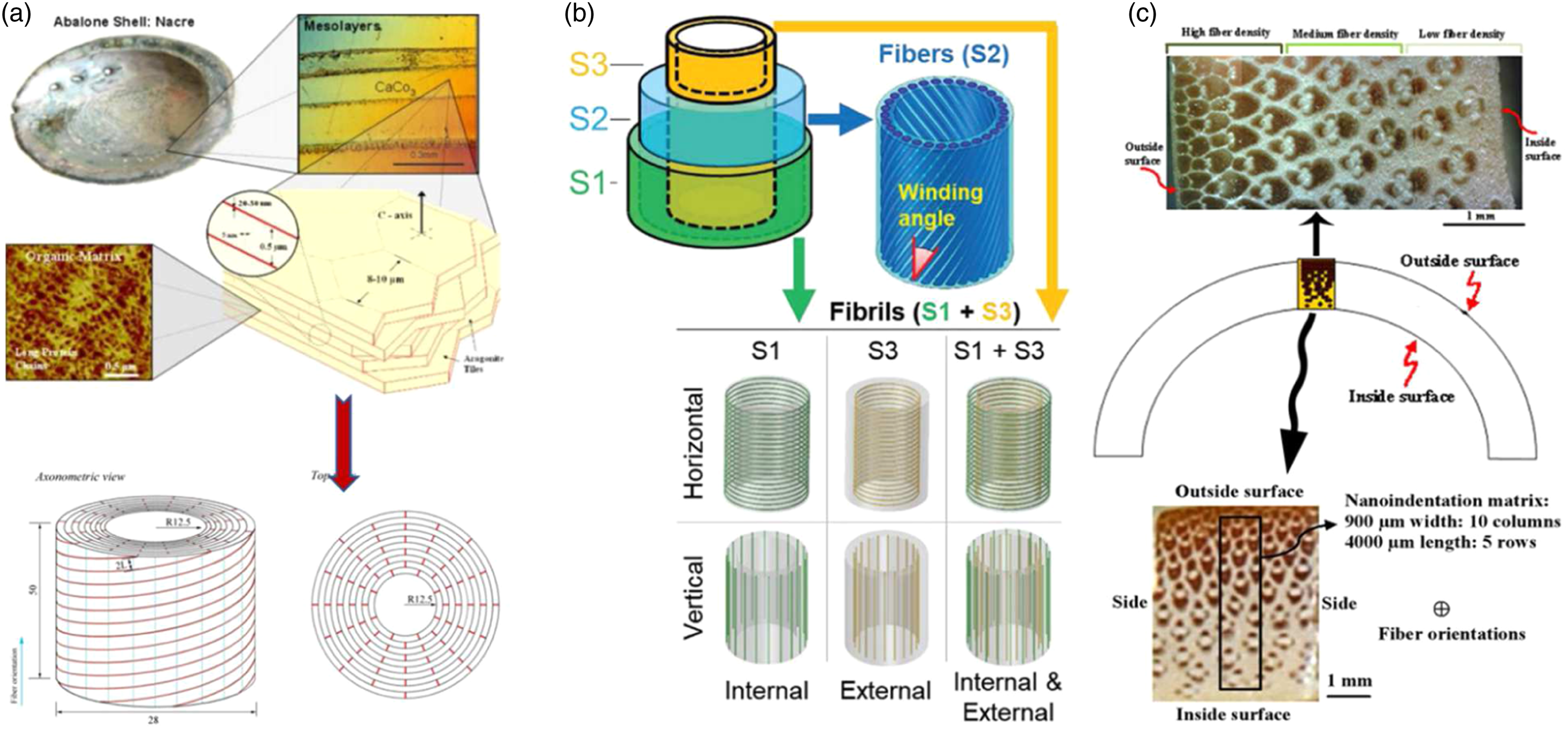
designed a carbon/epoxy composite tube mimicking the interdigitated and discontinuous design patterns of nacre structure (Figure 1(a)). They manufactured CFRP composite tube containing helical orientation with different angles through wrapping method. They found that the helical and nacre-mimicking discontinuous structures showed better crushing process and higher SEA compared to unidirectional continuous tubes. Zorzetto and Ruffoni
28
mimicked the wood structure and introduced a helix reinforced composite tube (Figure 1(b). The wall of the tube contained three layers with different orientation. The inner and outer tubes were composed of thin fibrils where the middle helicoidal layer has different helix orientations. They found that the thin fibrils oriented in circumferential direction considered the axial axis of the tube can greatly improve the SEA and Et. Besides the helix fibers oriented in 45° showed better energy absorption. Thus, the composition of circumferential and helix orientation can improve the energy absorption characterization of thin-walled circular tubes. Furthermore, bamboo owns a lightweight biological composite structure.11,29,30 The composition of bamboo material and the location of its bionic elements lead to withstanding extreme loading conditions including lateral and axial compressions. The vascular bundles, named as bamboo fibers, are placed longitudinally in surrounding organic matrix, as presented in Figure 1(c).31,32 But the effects of embedding fiber in bamboo organic matrix is not investigated yet. Quantitatively, the crush behavior and the energy absorption capacity of axial crushed of bio-inspired circular composite tubes based on layering configuration is still insufficiently studied and not well understood. Fiber patterns, such as woven, unidirectional continuous fiber and chopped random fiber, also have a significant effect on the crashworthiness characteristics of composite energy absorbents.11,33,34 So, more investigations are required to fully understand the effect of fiber architecture on the crush behavior of bio-inspired composite tubes and their capacity to absorb energy. Considering the traditional design of thin-walled circular tubes, many researchers studied the effects of various fiber orientation of E-glass fiber on crashworthiness behavior. Hu et al.
34
determined the crushing modes and absorbed energy of 759/5224 woven glass cloth/epoxy composite tubes with various fiber orientations. Their results demonstrated that fiber orientation has a great influence on crush parameters. M.Nalla Mohammad and Parveen Kumar
33
experimentally studied the effect of the fiber architecture of tubular composite cylinders, including unidirectional and woven glass and carbon fiber cylinders, under axial compression. The laying angles that they tested were [0/0/0], [0/0/90], [0/90/0], and [90/0/0]. Moreover, in order to improve their insight into progressive failure, they carried out a numerical analysis through ABAQUS/Explicit. In another study conducted by Hull, the effect of fiber orientation in filament wounded glass/polyester tubes with θ in the range ± 35°, 90° was examined.
7
Hull’s result demonstrated that the energy absorption response of composite tubes increased by enhancing the fiber orientation. He attributed the changes in the crushing behavior of tubes to the difference between induced failure modes in the variation of fiber angles. Farley and Jones
35
also discussed the composite tubes with a fiber orientation of [0/ ± θ] made of glass and carbon fiber sheets under quasi-static axial crushing. The capacity to absorb energy in the glass/epoxy cylinders gained non-linearly by increasing the θ; however, this value for carbon/epoxy tube decreases non-linearly. Generally, these writers recognized that the fiber direction of [0/ ± 45] is the best for fiber glass epoxy tubes. Seyed Morteza Hosseini and Mahmoud Shariati
8
considered the effects of layer configuration, reinforcing fibers, and the fabrication process in fabricating thin-walled tubular composite shells and examining their capacity to absorb energy. The findings were that the stacking sequence schemes and the manufacturing quality directly affect the modes of crushing. Ghasemnejad et al. studied the impact of fiber orientation and the stacking sequence of GFRP composite crashboxes made of glass fiber/epoxy. Axial compression tests were conducted on samples with [ ± 60]10, [02/ ± 45]5, [0/90]10, and [0/90]5S fiber configurations. They showed that inter-laminar fracture toughness withstands dominant central inter-wall cracks in progressive crushing failure and proper composite structural designs under crushing forces are attainable by a suitable selection of the layering-up configuration to achieve the greatest possible inter-laminar fracture toughness and improved SEA.
36
Additional to insufficient studies on layering configuration and stacking sequence corresponding to bio-inspired circular tubes, the effect of tube diameter, which difficilitates the manufacturing process and deteriorates the crushing behavior of composite tubes, is not understood well. Because the tube diameter and fiber orientation are significantly the functions of each other, this function is effective in the manufacturing process and failure mechanisms of composite tube, respectively. On the other hand, the composite energy absorber benefiting proper progressive crushing and energy absorption efficiency is valuable and useful when the ease and costs of manufacturing method alongside employing functional material are considered. Among all manufacturing methods, the hand-laying up is a promising way to obtain all mentioned goals achieving an optimal design of energy absorber and a higher rate of production. Although using the hand-layup method is easy and cost-effective, some manufacturing limitations and criteria depend on the relation of adopted material and manufacturing method. Manufacturing bio-mimicked circular tube is arduous due to the difficulty of manufacturing and limited dimensions. Thus, the former manufacturing methods of composite tubes need to be modified and evaluated as some references utilized modified methods.37,38
Although the field of axial crushing of tubular composites has often been explored, numerical models anticipating the axial collapse behavior of composite tubes are confined to the influence of the ply pattern of composite layers.30,37–39 Because of the significant expense of directing test surveys, dependable mathematical models are needed that are equipped for anticipating the crush behavior of composite components. Some attempts have been made to create express finite element models, with varying success. For instance, Han et al. 38 tested braided fiber reinforced plastic specimens made of unidirectional pultruded tubing over wrapped with ± 45°. Parametric numerical studies on the crushing response of tubing have been conducted to examine the impact of the loading conditions, the length and thickness of the tube and the type of braid. They have predicted the crushing response and energy absorption capacity of hybrid composite tubes based on Chang–Chang’s failure criteria in the LS-DYNA code. Nevertheless, these mathematical models, aside from the model created by McGregor et al. 40 can barely reenact the energy absorption qualities and the crushing failure mode at the same time. For this reason, ways of building powerful numerical models to anticipate the crashworthiness characteristics and failure modes of composite components merit further enquiry. Hitherto, many numerical surveys of the response of axially crushed composite cylinders have been published. Composite cylindrical shells composed of woven carbon/epoxy laminates under quasi-static axial crushing were simulated by Mamalis et al. 39 based on the Tsai–Wu failure criteria incorporating a three-layer FEM in the LS-DYNA3D code. Their model accurately provides the initial peak force, but the predicted mean crushing load and SEA by this model were lower than the experimental results. Paolo Feraboli et al. 41 adopted MAT_54 to simulate a sinusoidal composite sample subjected to axial crushing and discussed the sensitivities of model parameters. Other than these, numerous scholars 42–45 have used similar procedures and material models to simulate the crush response of composite structures. For instance, Jiancheng Huang and Xinwei Wang conducted axial compression tests on CFRP composite tubes to investigate their crushing behavior. Numerical simulations, as opposed to experiments, have also been employed, based on Chang-Chang’s failure criteria, to represent the modes of failure of composite tubes and high levels of correlation achieved. 46
This research examines the effect of a novel layering configuration of circular composite tubes inspired by biological material properties under quasi-static axial compression. The tubular specimens, comprising of (W) and (UD) E/Glass fiber sheets were manufactured using a modified hand laying-up technique. Due to the limits of dimensions and material characteristics, several combinations of W and UD fiber sheets were created to get optimal crushing behavior and acceptable manufacturing quality by considering the biological geometries. Moreover, simulations, based on a material model (MAT-54) as opposed to experimental tests, were performed and validated to evaluate the influence of various layering schemes on energy absorption and the crushing modes of experiments. This was followed by a discussion of the failure mechanisms of bio-inspired composite tubes and the correlations between layering configuration on the crashworthiness characteristics of samples. It was observed that the layering design significantly enhances the energy absorption properties of composite tubes while considerably altering the modes of deformation.
Design strategy and crashworthiness evaluation
Bio-inspired design of layering configuration
The goal of the design of GFRP thin-walled tubular energy absorbers is to improve energy absorption1–54 performance while minimizing weight. Fiber orientation and layering configuration have a substantial influence on crushing behavior and energy absorption capability, according to previous studies.27,28,31,32 Higher levels of energy absorption capacity can be achieved by mimicking biological materials and related patterns, such as bamboo structure. Figures 1(c) and 2(a) illustrate that the vascular structure has a gradient distribution pattern, with the number of vascular bundles being higher closer the bamboo structure's outer surface. Furthermore, the vascular bundle is defined as a series of longitudinal bundles encircled by organic matrix.31,32 Therefore, the wall structure design was based on vascular structure of bamboo which is containing the plain woven and UD glass fiber. The bamboo is strengthened by longitudinal vascular bundles and organic matrix, as presented in Figure 2(a), where the vascular bundles and organic matrix are next to each other. In other words, the integration of the vascular bundles and organic matrix gives the bamboo its strength. This behavior is primarily noticed at the outside section of the bamboo structure. On the other hand, the resistance of bamboo in front of axial and lateral loading originates from resisting the buckling of longitudinal vascular bundles by circumferential reinforcement of organic matrix. Due to the higher levels of load-bearing capacity and buckling resistance, especially in cross-sections accommodating more longitudinal vascular density in the outer layers of the wall structure, it is logical to consider the vascular bundles surrounded by organic matrix as a plain woven; additionally, the circumferential UD glass fiber plays the reinforced organic matrix role corresponded to the inner part of the bamboo structure with lower levels of longitudinal vascular density. (a) Organic matrix reinforced by gradient distribution of vascular bundles. (b) and (c) different layering configuration design.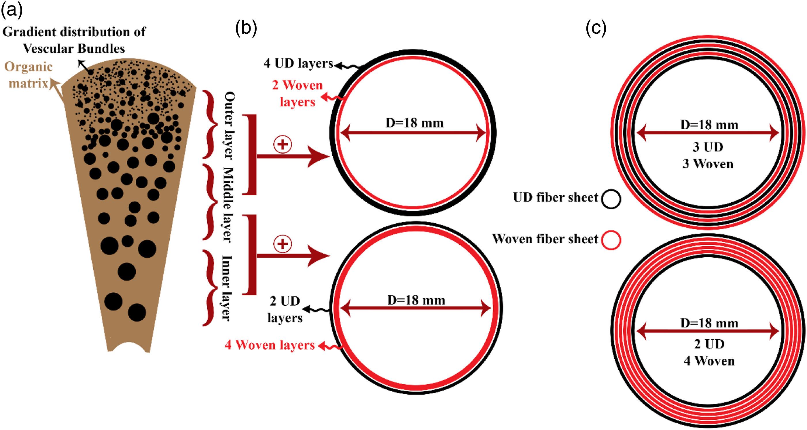
As shown in Figure 2, the inner tube diameter is designed to be similar to the real diameters of bamboo. 31 The number of layers and the height of the specimens were adjusted to 6 and 90 mm, respectively, to make a proper comparison of diverse bio-inspired composite tubes. Several possible stacking sequences are established due to manufacturing problems, which will be addressed in depth in the following session, so that seven layering configurations are investigated experimentally and others using a FEM method. Plain woven fiber sheets, which act as both a vascular and an organic matrix, are encircled by circumferential UD fiber sheets, which act as a reinforced organic matrix. It is necessary to remark that varied number of woven and UD layers are made considering varying gradient distribution of vascular bundles respectful to distinct distribution patterns (see Figure 2(b). Besides, additional stacking sequences including six layers of woven, six layers of hoop UD fiber are fabricated to explore the layering configuration effects of sub-part of the bamboo structure on manufacturing process and crushing behavior. Figure 2(c) illustrates various design examples demonstrating different stacking configurations near to actual bamboo structure.
Crashworthiness evaluation
Several assessment indicators are described from the load-displacement curves in order to evaluate the performance of an energy absorber structure. The crushing curve presented in Figure 3 can be divided to four main stages including the linear elastic stage correspond to elastic behavior of the composite tube; transient stage being defined as a sharp drop in crushing load and a transition from elastic to crushing behavior; the crushing stage which is a stable fluctuating of the load, and the densification stage correspond to sudden increment in crushing load. Typical Load-Displacement Curves of an energy absorbing structure.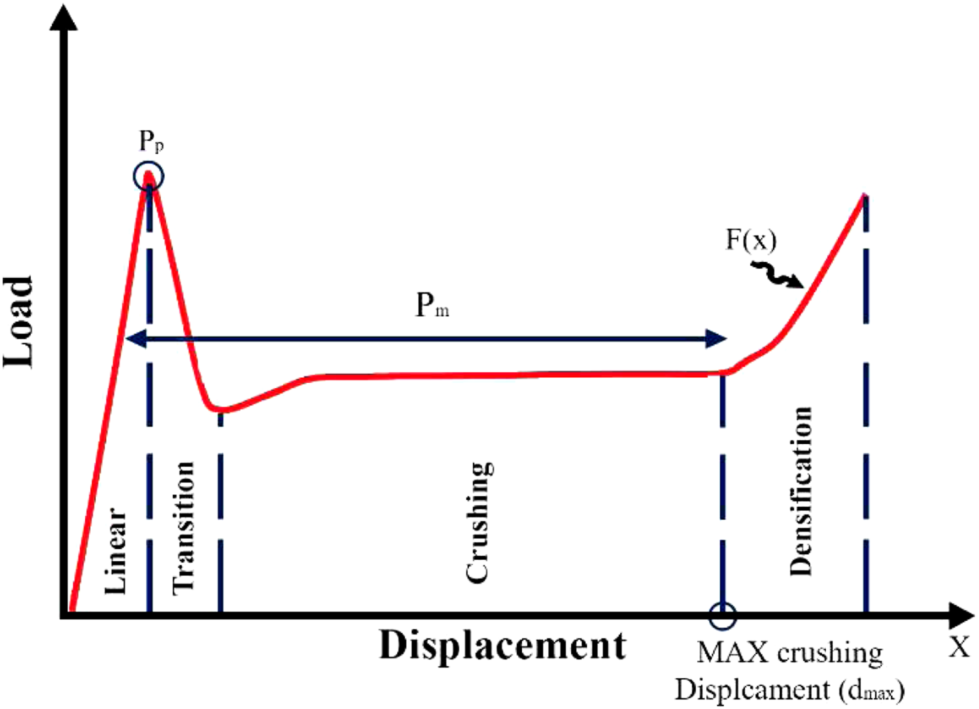
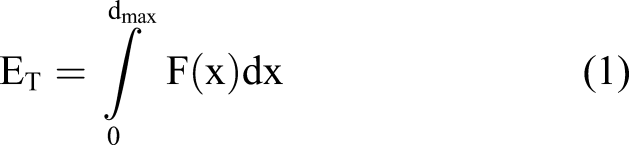
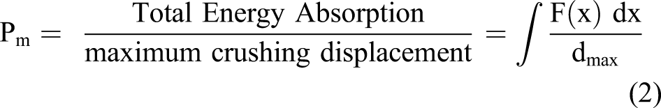
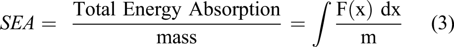
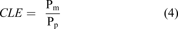
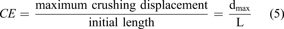
From the load-displacement plots presented in Figure 3, the following crashworthiness parameters were characterized: 1. Peak load (Pp) is the maximum load at early stage of crushing. 2. Total (Et) is defined as the area under the load-displacement curve and formulates 3. Mean crushing load (pm) is the ratio of the total absorbed energy in the crush zone to the ultimate displacement in this zone 4. (SEA) which is equal to the total absorbed crash energy divided by the mass of the crushed portion of the specimen 5. Crushing load efficiency ratio (CLE) being defined as the ratio of the average crush load to the peak load 6. Crushing efficiency (CE) ratio corresponds to the ratio of the crush length to the full length of the specimen and is formulated as
Fabrication and experimental procedure
Fabrication and materials
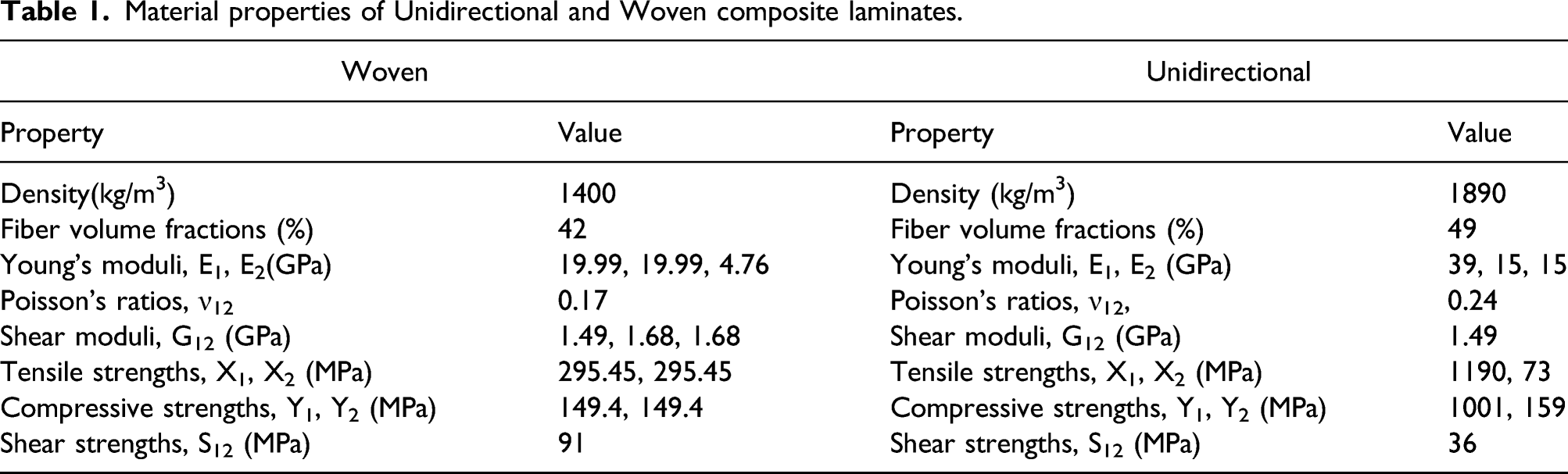
Material properties of Unidirectional and Woven composite laminates.
According to the design stage, addition to manufacturing tube with bamboo-inspired material orientation including various combination of woven and UD fibers, other stacking sequences such [FW]6, [CW]6, [902/02/902] were fabricated to investigate the manufacturing limitations in detail. Because manufacturing of the bio-inspired tubular composites is geometrically difficult due to the high flexural strength of UD glass fibers through 0-and 90-degree directions while the fibers are being wrapped around the cylindrical Teflon mandrel with 18 mm diameter. The outcome of the fiber’s bending strength limits the strength of the final product and interlaminar adhesion. Therefore, in manufacturing composite tubes the diameter of the sample should be considered critical. The hand layering of such fibers also makes it impossible to achieve proper interlayer and smooth surface adhesion in composite tubes made entirely of UD fibers. Moreover, manufacturing the layering configuration inspired from bamboo’s wall is attained by combining woven fabrics with UDs, played as reinforced organic matrix and pure organic matrix, respectively. These make the fabrication process much simpler and enable the UD fibers to be wrapped conveniently.
The innovations in this method are cutting the costs and increasing the production ratio. Besides, the other innovation is in the manufacturing process which is the use of polymer semi-pipes to create pressure over the wrapped layers of fabrics around the Teflon pipe and the removal of excess resin, during the manufacturing process, by embedding Dacron layers. This, unlike the conventional hand layering up method, resulted in a very smooth outer surface. A schematic of fabrication process is illustrated in Figure 4. In order to easily separate the inner and outer mold parts from the specimens, a wax discharge agent was applied to the surface of the central Teflon pipe. The glass fiber sheets impregnated with Epoxy were wrapped over the Teflon mandrel and overwrapped with Dacron plies. To obtain the desired thickness of glass fiber sheets, pre-tensioning was applied during the manufacturing process. The ends of the composite tubes were grounded to guarantee that they would be free from burrs or unevenness at either end. All the specimens were fabricated under the same conditions and they all had six layers. To achieve accurate test results with closely similar geometric and mechanical properties, three samples of adequate length were produced from each Teflon mandrel; in other words, three specimens per each stacking sequence have been manufactured. Thereafter, consistent with the required lengths for the experiments, the composite shells were trimmed with specific cutting tools. Fabrication process of tubular composite shells (a) applying the wax and wrapping the prepregs around the Teflon mandrel, (b) wrapping the Dacron sheets (c) finishing the process by installing the outlet PVC semi-pipes and fastening the holders.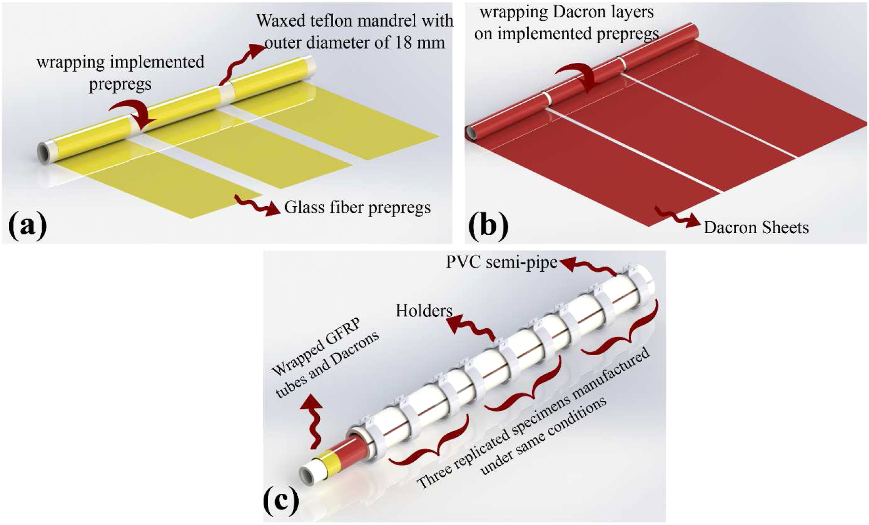
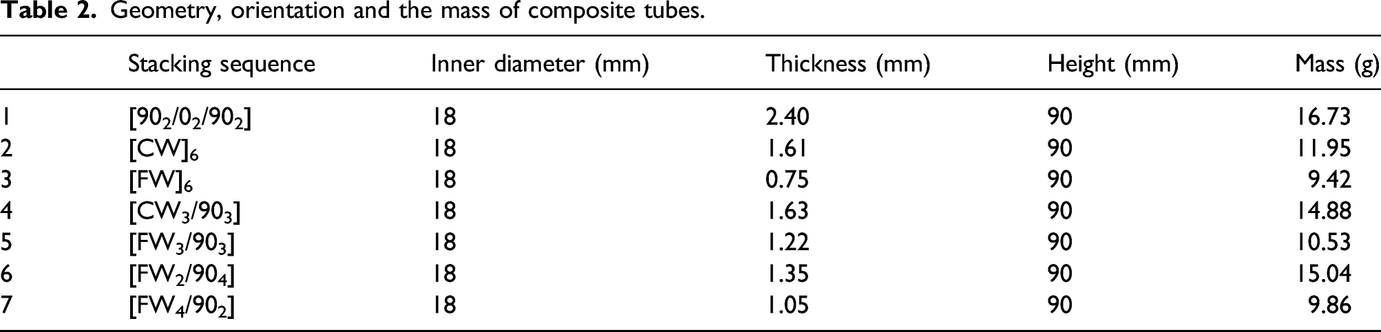
Geometry, orientation and the mass of composite tubes.
Mechanical tests
Crush tests were performed on glass fiber tubes quasi statically under axial compression test by an Instron Universal Testing Machine with a maximum load of 300 kN, at a cross-head speed of 5 mm/min. Before testing, it was necessary to ensure that both the moving and the stationary platens were located parallel and accurately coinciding and the tube was located centrally between them. Figure 5, shows the actual test configuration and dimensions. The crush load-displacement curve of the specimens was recorded automatically on a data acquisition system. For each cylindrical sample three test replicates were examined for data reproducibility and to ensure experimental precision. Test setup for the axial compression testing of composite tubes.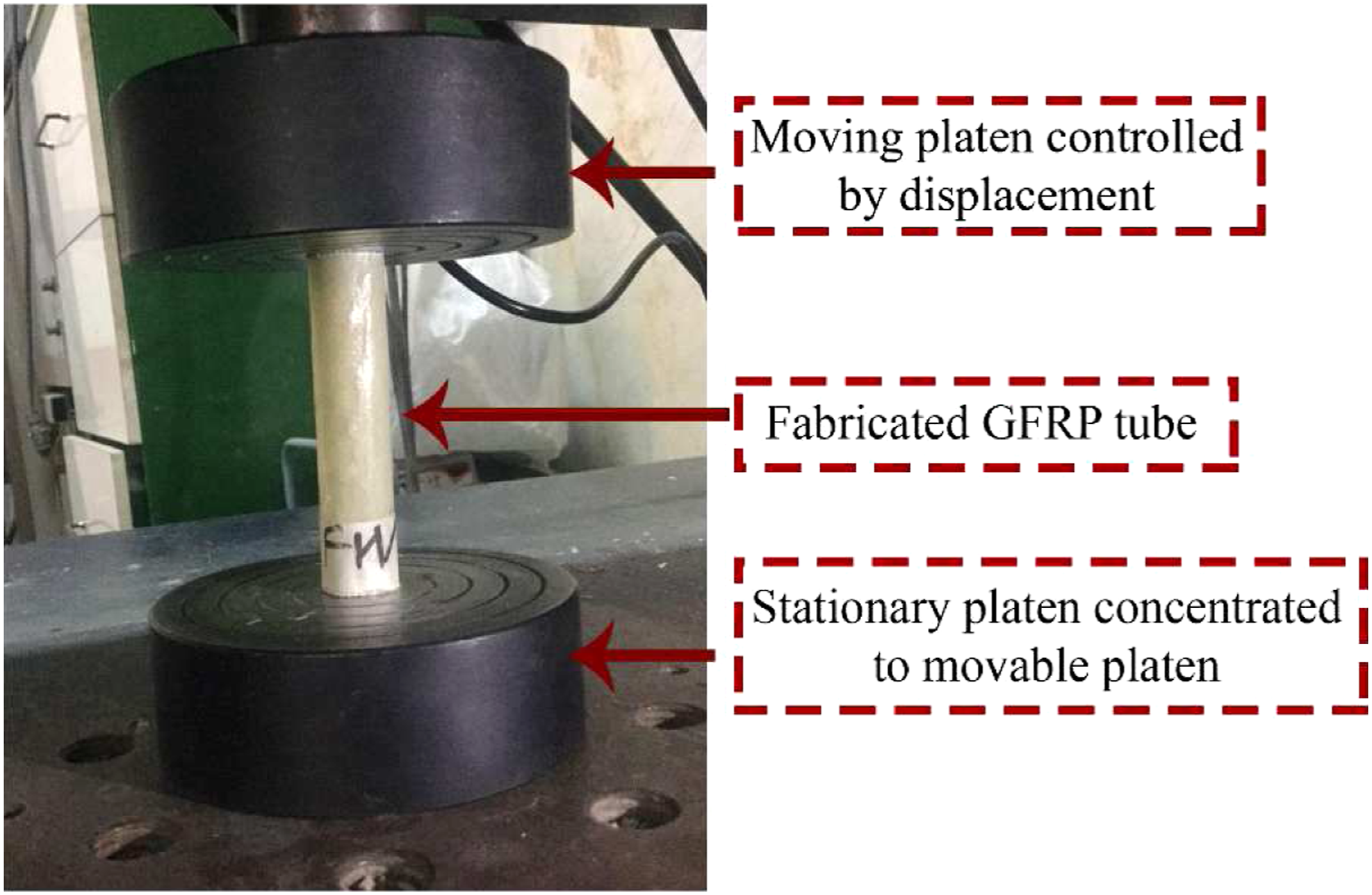
Features of numerical strategy
In order to obtain and investigate the compressive properties and crush response of bio-inspired fiber-reinforced composites, the experiment used the explicit LS-DYNA constrained element code approved by many researchers.39,46,49 The modeling strategy adopted the multi-layered approach so as to predict correctly the damage mechanisms of the composite tube, such as the growth of the central crack and the delamination of the layers. It was considered that in experimental tests, the composite tube consisting of three fine woven layers combined with three UD layers showed better results; these will be discussed in detail below, in the results and discussion section. [FW3/903] stacking sequence is the basis of the modeling, and this particular stacking sequence was examined in parametric studies.
Samples were modeled by rectangular shell elements including the six-layer cylindrical shells of Belytschko-Tsay (ELFORM number 2), in which one integration point for each layer is considered. Figure 6 illustrates the layers separated to clarify the shells. Hourglass effects and the Flanagan–Belytschko stiffness form of hourglass control were exploited to intercept the deformation of integrated shell elements by something non-physical.
50
Cylindrical shell layers including six separate layers representing the unidirectional and fine woven fiber shells.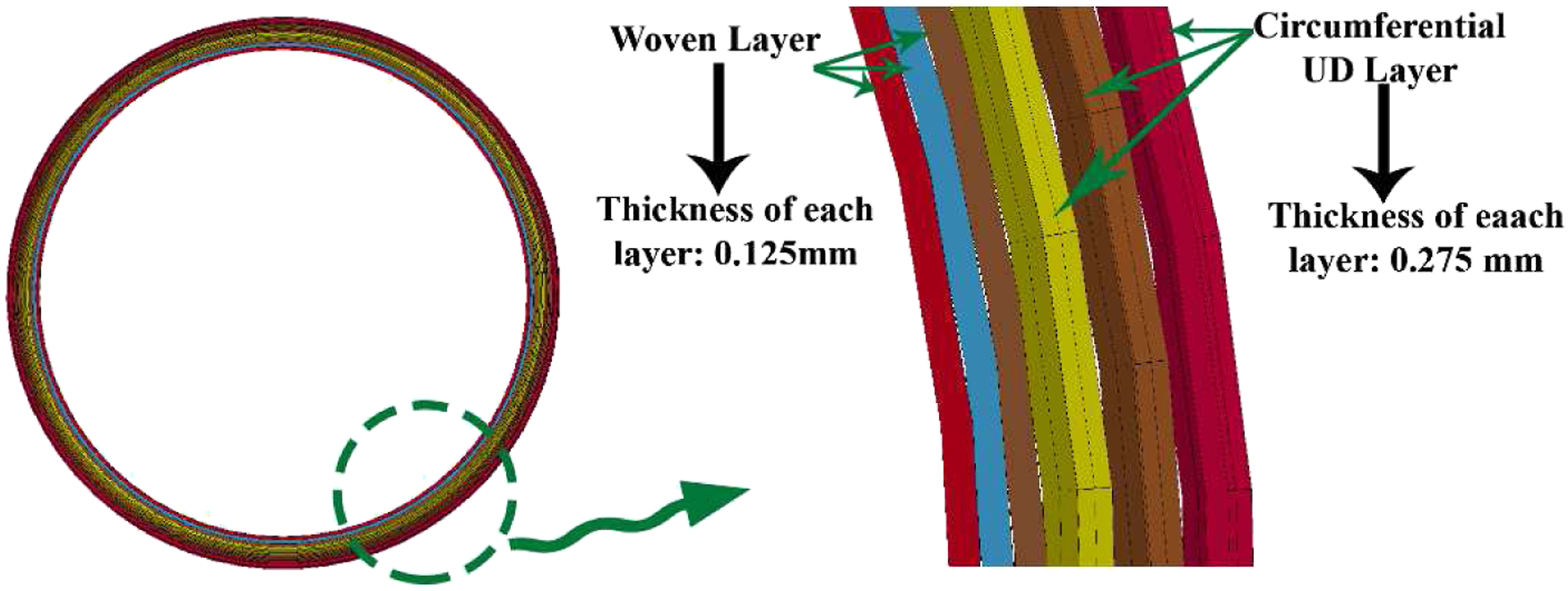
In order to observe the catastrophic failure in the composite tube, the two ends of the tube remained unconstrained and its upper end was subjected to quasi-static axial compression by the moving platen at a loading rate of 100 mm/s. The platens were designed with solid elements in which Young's modulus, density, and Poisson's ratio were considered: 200 GPa, 7772 kg/m3, and 0.27, respectively. Moreover, in the axial direction, the upper platen moves downwards only and all the degrees of freedom of the lower platen are completely constrained and fully fixed. To reduce the number of time steps during FE analysis, the density of the GFRP material was multiplied with 100. Thus, the kinetic to internal ratio was extracted and illustrated in Figure 7 to ensure that the kinetic to internal ratio is less than 5% [14–15 CFRP]. The contact between the tube and the platen, as well as the contact between the adjacent and non-adjacent layers, which are defined by the contact algorithms, are described in the following section. The detailed mesh convergence on FE tubular models was also studied by discretizing the model. It was calculated that a mesh size of 1 mm was optimal for studying the crashworthiness of composite tubes. Kinetic to Internal energy ratio of [FW3/903] stacking sequence.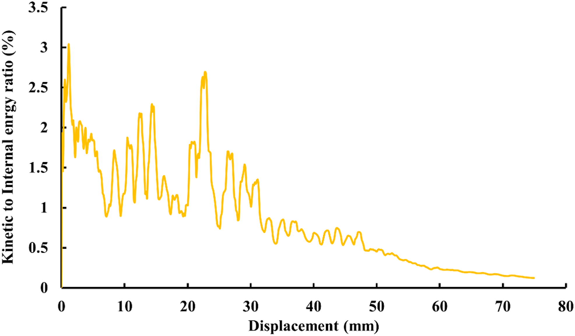
Damage material model
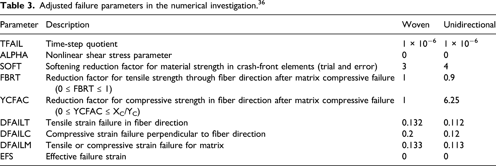
The 55/54 material model is reported to be one of the most effective models available for composite in LS-Dyna. 50 The Chang-Chang damage model is used only for thin shell elements. The load-displacement curve was predicted close to the experimental results. Moreover, using a multi-layer approach allows suitable progressive crushing to ensue. The undamaged model behaved in a linear elastic way while the material behaved in a non-linear way whenever damage was initiated. In this material model, the stresses changed through linear elastic behavior until the stresses so far developed had reached compressive and tensile strength in three principal directions. After this, the strain on the fibers and the matrix, as well as the shear stress of the composite, increased to specified values, resulting in element deletion while the current developed stresses remained constant. 50
Adjusted failure parameters in the numerical investigation. 36
Delamination modeling and contact definition
To achieve proper numerical results comparable to those of an experiment, it was a crucial part of the simulation to specify the contact algorithm. To investigate and demonstrate the delamination between layers, especially between the UD and the fine woven fabrics, five interlayer contacts *CONTACT_AUTOMATIC_ SURFACE_TO_SURFACE_TIEBREAK were defined. The tiebreak option enabled the contact surfaces to be detached after reaching maximum normal stress (NFLS) or shear stress (SFLS). The tiebreak failure criterion in the algorithm was given by the following expression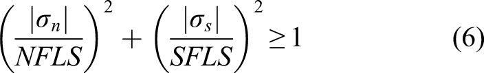
Results and discussion
Bio-inspired thin-walled composite cylinders were tested under quasi-static axial compressive loading, and their load-deformation histories were recorded to calculate the parameters of crashworthiness. In addition, the corresponding damage patterns and crushing characteristics were captured and discussed. The results obtained for the composite tubes are presented on the basis of their layering configuration. Typical load-displacement curves of axially crushed tubular composite structures with different layering configurations are shown in Figure 8. Also, the load-displacement curves are the mean trend of each stacking sequence in terms of three replicate per stacking sequence. It is evident from the diagrams that the curves belong to two specific phases: pre-crushing and post-crushing. In the pre-crushing phase, the crushing load increased rapidly to peak load in elastic stage. Meanwhile, due to the localized stress concentration, interlaminar and intralaminar cracks originated under the platen. After the first peak load, the samples illustrate different post-crash behavior, categorized as stable progressive crushing and catastrophic failure. Herein, the full UD ([902/02/902]) and full coarse woven ([CW]6) specimens follow the same trend where three incremental peak loads accumulate after minor crushing. In samples consisting of full UD fiber of a minimal 33 mm crush length, a circumferential cracks was generated followed by slippage of the tube under the platen. The full coarse woven tube, after 9 mm displacement, encountered catastrophic failure in the mid-length of the specimen. The full fine woven ([FW]6) tubes followed a small displacement by catastrophic failure, due to the sudden growth and propagation of their circumferential and interlaminar cracks, and the tube lost its load-bearing capacity. Diagram of manufactured composite tubes showing the load-displacement obtained.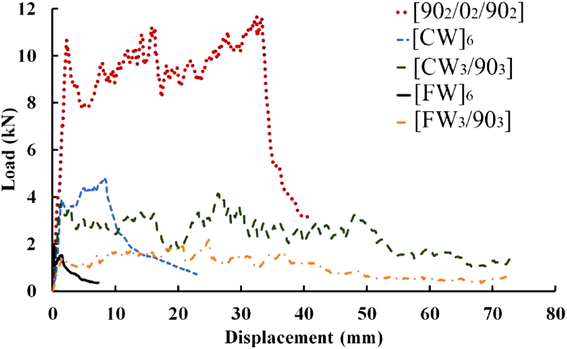
The [FW3/903] and [CW3/903] tubes showed stable progressive crushing behavior during axial compression after the first peak load value of 1.55, 2.30 kN up to 72 mm displacement, respectively. During the experiments, some cracking sounds were emitted which can be attributed to the fluctuations observed in the load-displacement diagrams. Similar results were also reported by Moinifard et al. 1
Identification of damage mechanisms
In the investigation of crashworthy energy absorbents during an accident, consideration must be given to the induced damage mechanism because progressive failure would provide safely smooth decelerations (due to stable impulsive force).51,52 The two primary failure mechanisms of composite cylinders are progressive and catastrophic failures, subsequently marked as Modes I and II. Mode I refers to the progressive crushing of an axially composite tube. The stable progressive crush can be attributed to a localized failure that started from the top surface of the specimen and proceeded by one of two sub-modes. Catastrophic failure (Mode II) occurs through the sudden cutting off of axial fibers and circumferential crack growth.
As illustrated in Figure 9, the dominant energy dissipation mechanisms in Sub-Mode l are governed by the formation of internal and external fronds as petal-like shapes bending inwards and outwards. Any further increase of compressive loading causes the annular debris wedge to be compressed and to penetrate the tube wall and subsequently form the internal and external fronds. In this mode, friction resistance between the internal and external fronds and the debris wedge, as well as the loading platen, could make a considerable contribution to the dissipation of energy. Moreover, the growth of inter-laminar cracks for delamination requires energy which generates interlaminar debonding through matrix breaking and causes friction between the delaminated layers, which also dissipates energy. Damage mechanisms through Sub-Mode I and Sub-Mode II.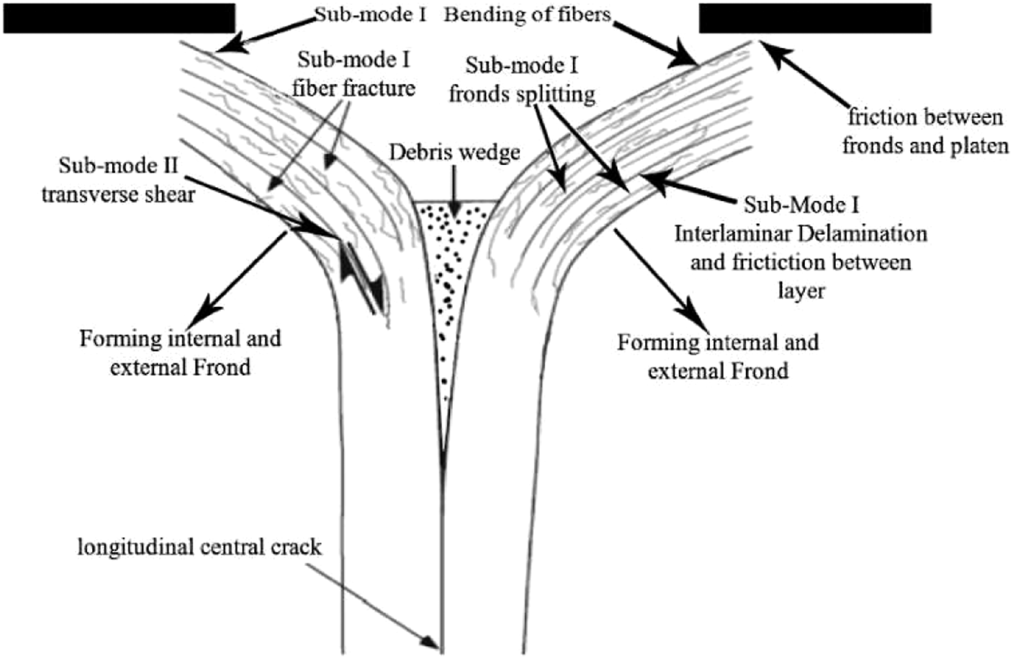
Sub-Mode II comprises the transverse shear crushing mode, whereas Sub-Mode I exhibited an ideal crushing energy dissipation mechanism for composite tubes with privileged capacity for absorbing energy. According to the crushing process of [FW3/903] and [CW3/903], the length of the central crack in Sub-mode II was between 1 and 10 times the thickness of the laminate as analytically demonstrated by Farley and Jones.36,53 A Fiber-matrix fracture along with interlaminar and longitudinal crack growth and friction between the loading platen and splayed materials consumes a considerable amount of energy. The crush zone morphologies of compressed specimens are presented in Figure 10. According to the experimental observations, the failure behavior of composite tubes is very greatly affected by the arrangement of fiber and the layering configuration. Post-crushed profiles of glass fiber composite tubes (a) [902/02/902], (b) [FW3/903], (c) [CW3/903], (d) [CW6], (e) [FW6].
In Figure 10(a), full UD samples show a mixed-mode failure. Initially, Sub-Mode I and II were thought to exemplify the major failure mechanisms. In compression loading, axial stress concentration at the lower end of the tube provoked the bending of axial fibers, resulting in a circumferential crack. Following this, the weakening of the adjacent part of the tube generated another circumferential crack resulting in Mode II and the specimen slipped out of the platens.
Specimens consisting of plain FW and CW failed in catastrophic failure mode and once the load reached the first peak, circumferential shear fracturing appeared and the load suddenly dropped. However, manufactured tubes using CW fiber sheets showed little progressive crushing. In woven fabric, the peripheral stress reaches its critical point sooner than the axial stress, because the fiber properties are equal in both directions, 0 and 90°. Due to the low diameter-to-length ratio of the tube, the longitudinal stress is applied at a lower level and reaches its critical value earlier. In addition, the bending of axial fibers accelerates the growth of circumferential cracks.
As shown in Figures 10(b) and (c), [FW3/903] and [CW3/903] samples were crushed in a progressive mode and the dominant progressive failure mode was Mode I, including fiber breakage, crack growth in longitudinal and circumferential directions, laminar bending, and the formation of internal and external fronds. Thus, the performance of the composite tubes due to the orientation of the fibers in a circumferential direction led to a controllable progressive crushing where various failure mechanisms went into action during loading. In these samples, the woven fibers acted as the core which were surrounded by hoop UD fibers and would display an efficient crush length.
Crashworthiness characteristics
The performance of a crashworthy component is primarily assessed on the basis of its general crush response, and whether its manufacturing process is simple and cost-effective. The crush response of an energy absorbing structure is defined by the following parameters: Initial (Pp), (P
m
), (SEA), (CLE), and (CE). In this manner, the values that integrate the data obtained from the load-displacement of the composite tubes are used to calculate the absorbed energy during compressive loading. By dividing the total absorbed energy by the weight of the intact specimen, specific energy absorption can be derived and is here reported in Figure 11. Corresponding absorbed energy and specific energy absorption of experiments.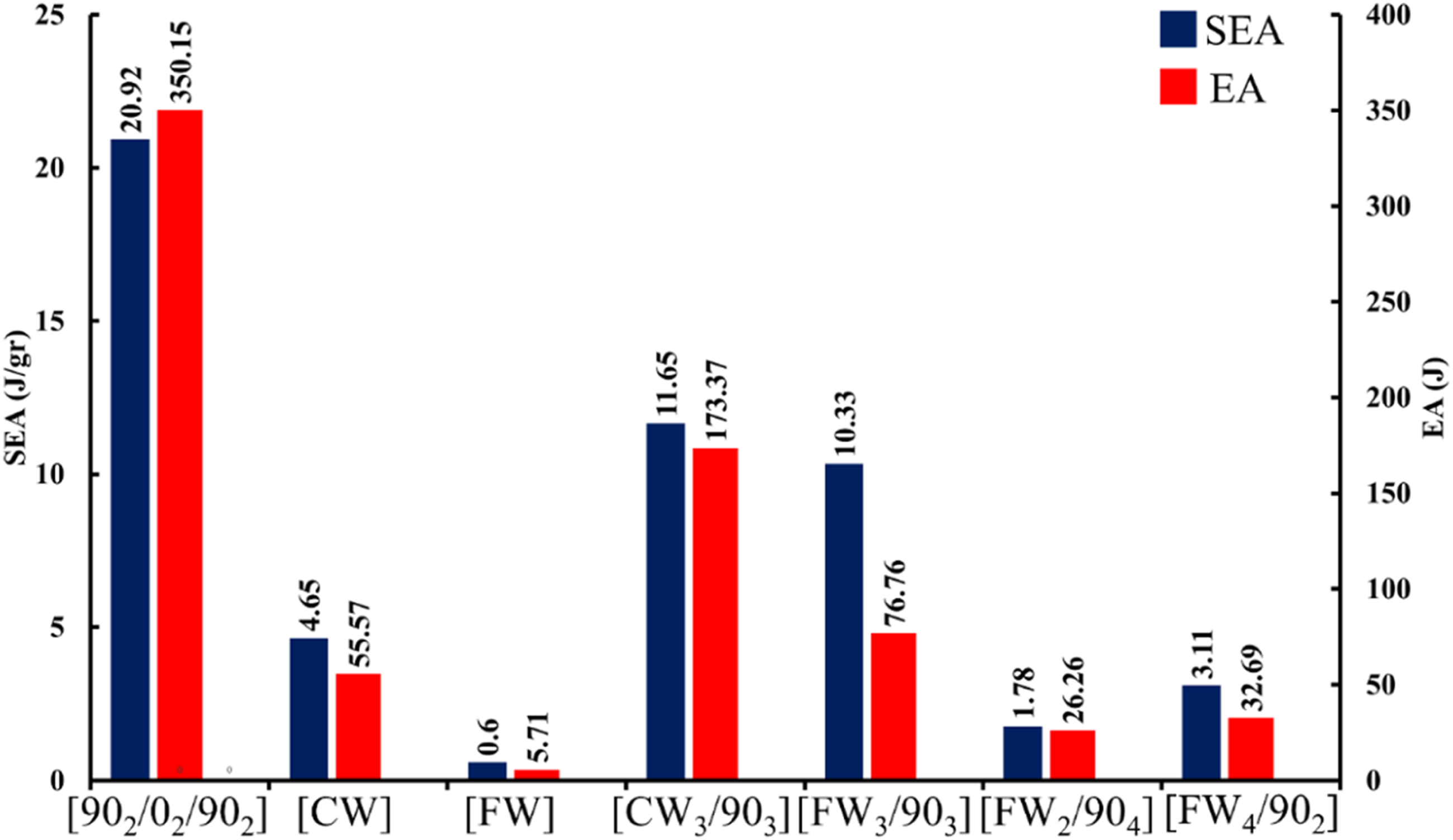
Summary of crashworthiness parameters obtained from the experiments.
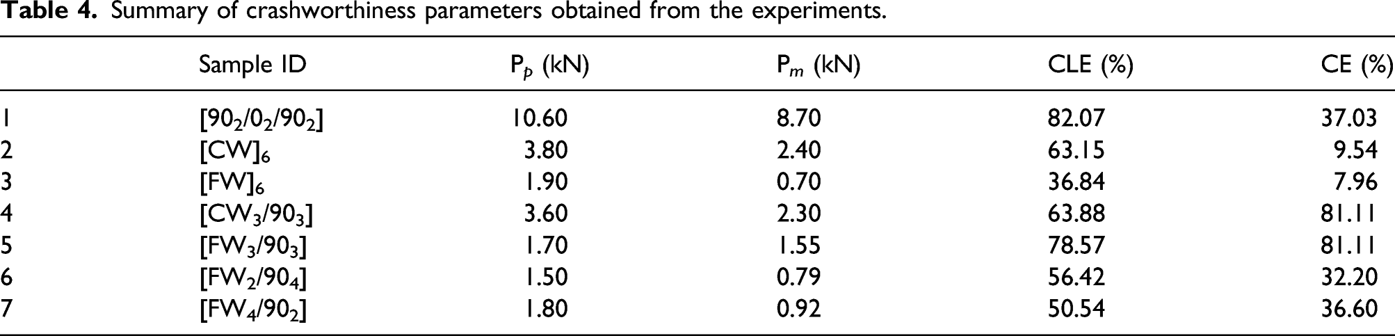
As an energy absorber, the highest CE is preferred. 54 According to the data presented in Table 4, all the specimens except [FW3/903] and [CW3/903] suffered catastrophic failure and their CE values were less than 50%, which is not efficient, considering that the CE value for hybrid tubes with equal woven and UD fiber is 81%.
The full UD specimen had the highest EA and SEA compared with the other stacking sequences because of its higher CLE and mean load and despite its lower CE value. But the [FW3/903] and [CW3/903] tubes had equal values of SEA while the EA of the [FW3/903] tube was much lower than the [CW3/903]. So, using fine woven fibers with circumferential UD fibers had a much greater effect on the SEA than the coarse woven fiber did. Using three layers of fine woven fibers with circumferential UD fibers rather than a full fine woven tube also increased the SEA ten-fold.
To summarize the first part of this research work, the following observations from the experimental part can be made and discussed.
One of the goals of this study is to facilitate the construction of composite tubes by the hand laying-up method to achieve suitable parameters of crashworthiness. Among the tested samples, the hybridization of fine woven with UD fiber in a circumferential direction gave the best results both as a convenient fabrication process and the level of crashworthiness in performance. The reason behind the use of hybrid composite fiber was to keep the advantages of both types of fiber and compensate for the weaknesses described in the previous section. Regarding these aspects, the hybrid composite structure represents supreme feasibility in the design and fabrication of composite energy absorbers. Generally, the purpose of involving two types of fiber in a solitary composite structure would be to improve both fibers and moderate some of their drawbacks.
Validation
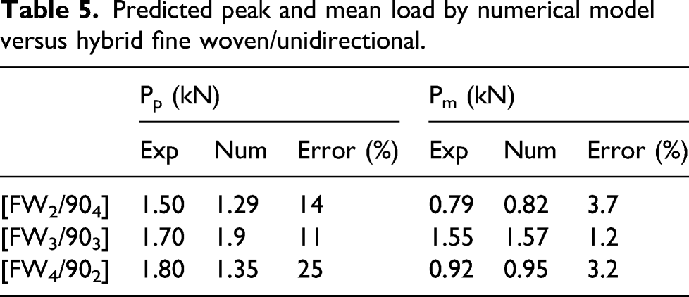
To confirm the reliability and accuracy of numerical analysis, the finite element models for the tubes which were fabricated from the combination of fine woven and circumferential UD fiber were validated against our experimental study. From Figures 12 and 13, it is evident that a desirable correlation is obtained between the experimental and numerical load-displacement curves. In Table 5, the Pp and Pm calculated from experimental and numerical load-displacement curves are tabulated to show the minor differences between them. Figures 14 and 15 show numerical failure modes simulated by the material model 54 for samples [FW3/903] and [FW2/904]. It is worth mentioning that the load-displacement curve as well as the failure mechanism of the [FW4/902] configuration was identical to that of the [FW2/904]. Comparison of Load-Displacement curves of the numerical and experimental results: (a) [FW3/903], (b) [FW2/904], (c) [FW4/902]. Comparison between numerical and experimental specific energy absorption of hybrid fine woven/unidirectional composite tubes. Predicted peak and mean load by numerical model versus hybrid fine woven/unidirectional. Progressive crushing history and crushed morphology of the experimental and simulation of the composite tubes composing [FW3/903] stacking sequence. Catastrophic failure of [FW2/904] in composite tubes and simulation.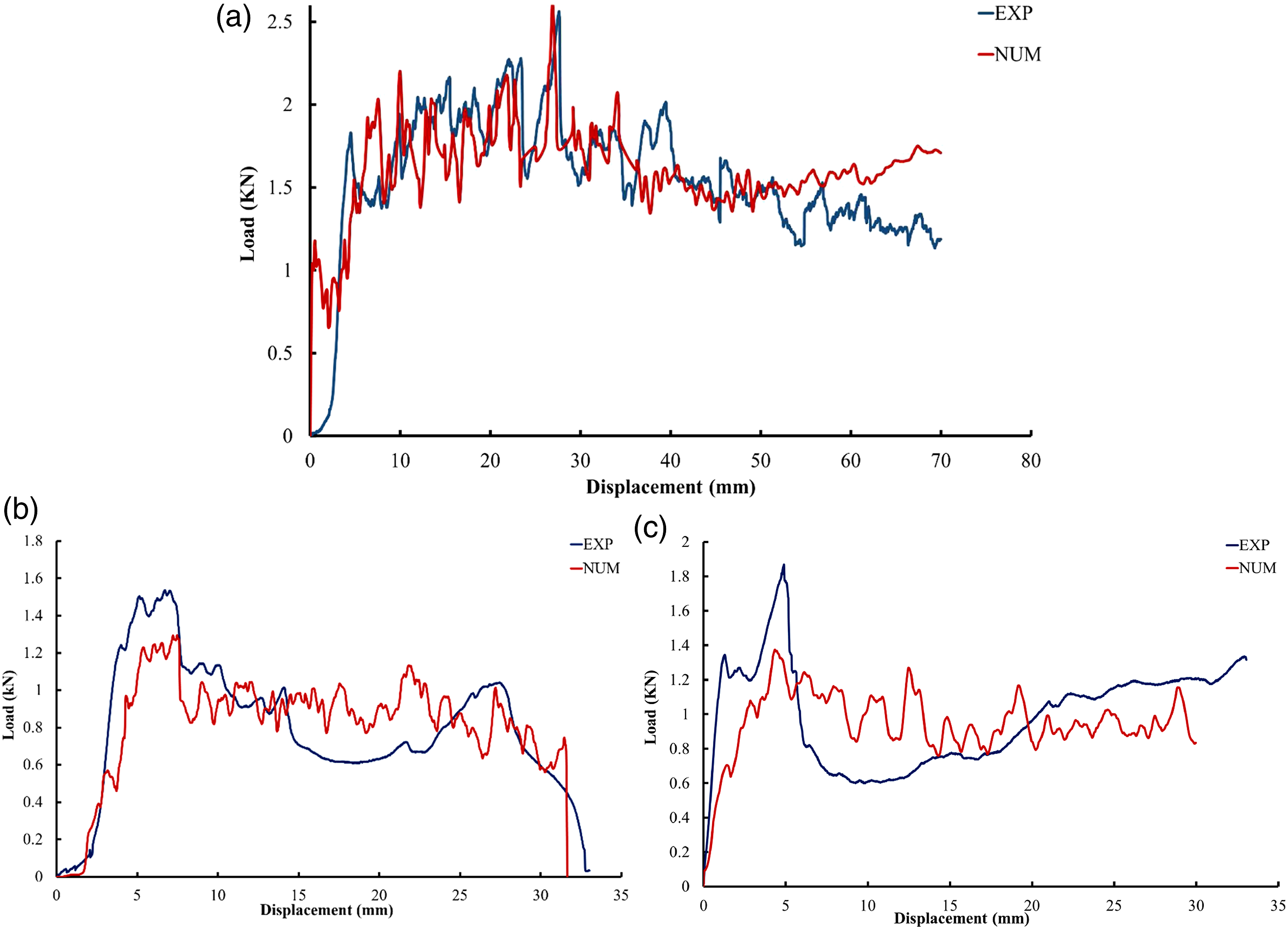
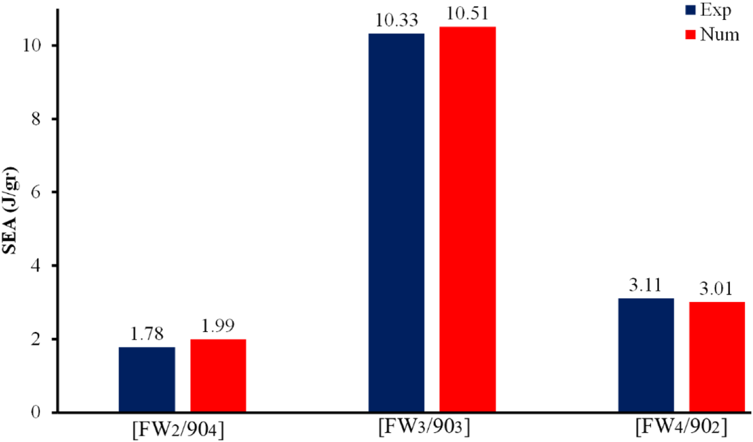
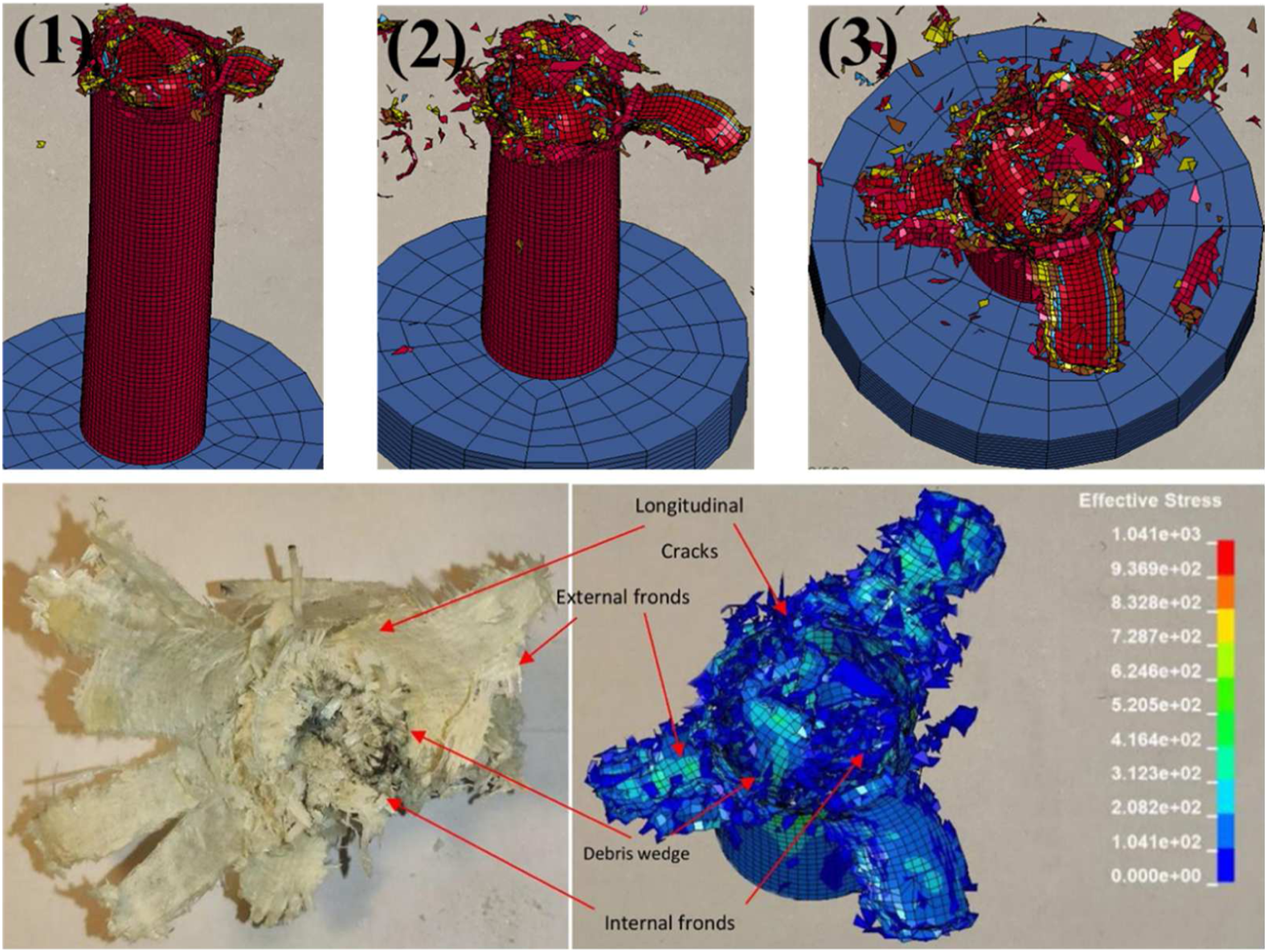
The numerical solution was able to predict accurately the trend of the graph and match closely. Figure 15 also shows the failed [FW4/902] specimen. However, because the element was removed to show this process, the outer and inner fronds were not shown correctly, although the model predicted the load-displacement curve and catastrophic failure well. The highest errors of Pm and SEA among all three samples was related to sample [FW2/904], and were 3.7 and 11%, respectively. The validation of the numerical model at the simulation of the crushing response of the tubes was based on a comparison of the load-displacement profile, Pp, Pm, overall damage mechanisms, and final predicted SEA, which was numerically monitored in LS-DYNA.
Numerical parametric study
Stacking sequences and fiber volume fractions of the numerical parametric study.
UD: Unidirectional.
Specific energy absorption:
According to the trend of the diagram in Figure 16, it is clear that if the volume fraction of woven fibers is less than 50%, two factors strongly affect the SEA: the location of the woven fibers, and the number of adjacent woven layers. According to the results, the placement of woven fibers in the outer layers and the placement of more woven layers next to each other increase the SEA. The tubes were enclosed in 50% of woven fibers, with three layers of woven fibers in the first three layers of the stacking sequence compared to three other stacking sequences with the same volume percentage of woven fibers. This made a significant difference in specific energy absorption and led to a 150% increase in SEA. As the volume fraction of woven fibers decreased, consequently, the location and the number of adjacent woven layers slightly affected the SEA. Increasing the volume fraction of woven fibers by more than 50% also did not significantly affect the SEA. Therefore, among the parametric study results, it is clear that one of the best choices regarding the stacking sequence is an equal volume fraction of woven and UD fibers. Specific Energy Absorption of different stacking sequences.
Crush efficiency (CE):
According to the calculated CE for various samples combining woven and UD fibers in Figure 17, as the volume fraction of woven fibers is less than 50%, more stability and progressive crushing can be achieved by increasing the number of adjacent woven layers placed in the outer layers of the tube. In tubes consisting of 33.4% woven fibers, the crush length of the [W2/904] was 57% lower than the [904/W2] composite tube. The crush length of the [W/904/W], in which the woven layers were not adjacent, was also lower than the [902/W2/902] and [904/W2] stacking sequences, and catastrophic failure was the dominant failure mode. When the volume percentage of woven fibers was more than 50%, the placement of hoop UD layers around the woven layers causes these fibers to surround the woven fibers like a belt, so preventing catastrophic failure and making the progressive crushing the dominant failure mode. Furthermore, where the other stacking sequences showed catastrophic failure, only the [90/W4/90] stacking sequence was capable of undergoing progressive crushing, absorbing the energy through different damage mechanisms as discussed above. Therefore, by considering the results related to the tubes consisting of an equal number of UD and woven fibers, it seems in conclusion that, regardless of the location and conjunction of the woven fibers, the equal number of UD and woven fibers preserves the progressive crushing process. Crush efficiency of different stacking sequences.
Crush load efficiency (CLE):
CLE indicates the uniformity of the crush-load–displacement curve, that is, the higher the CLE, the more efficient the structure. As shown in Figure 18(a) and (b), the value of Pp and Pm decreases with decreasing thickness and the increasing number of woven layers. However, the stacking sequence and the location of W and UD fibers affect the peak and mean load considerably for the different fractions of woven fiber volume. The tubes consist of 16.6% woven fibers; stacking the woven layer in the middle of the layering configuration brought the peak load down to 44% but the mean load increased by 15%, which raised the CLE value from 11.7% to 26.24%. According to the obtained results of the samples with 33.4% of woven fiber volume, although Pp was increased by locating the woven layers in the outer layers of the tube in contrast, Pm did not change significantly. In this fiber volume fraction sample [W2/904] had the highest amount of CLE. In the samples with the 50% woven fiber, the equal embedding of woven and UD layers in the inner and outer sides of the tube increased CLE. So, the mean load of the [W3/903] tube was 52.22% higher than in the three other cases with the same fraction of woven fiber volume. (a) Peak load, (b) Mean load and (c) Crush load efficiency corresponding to the numerical parametric study results.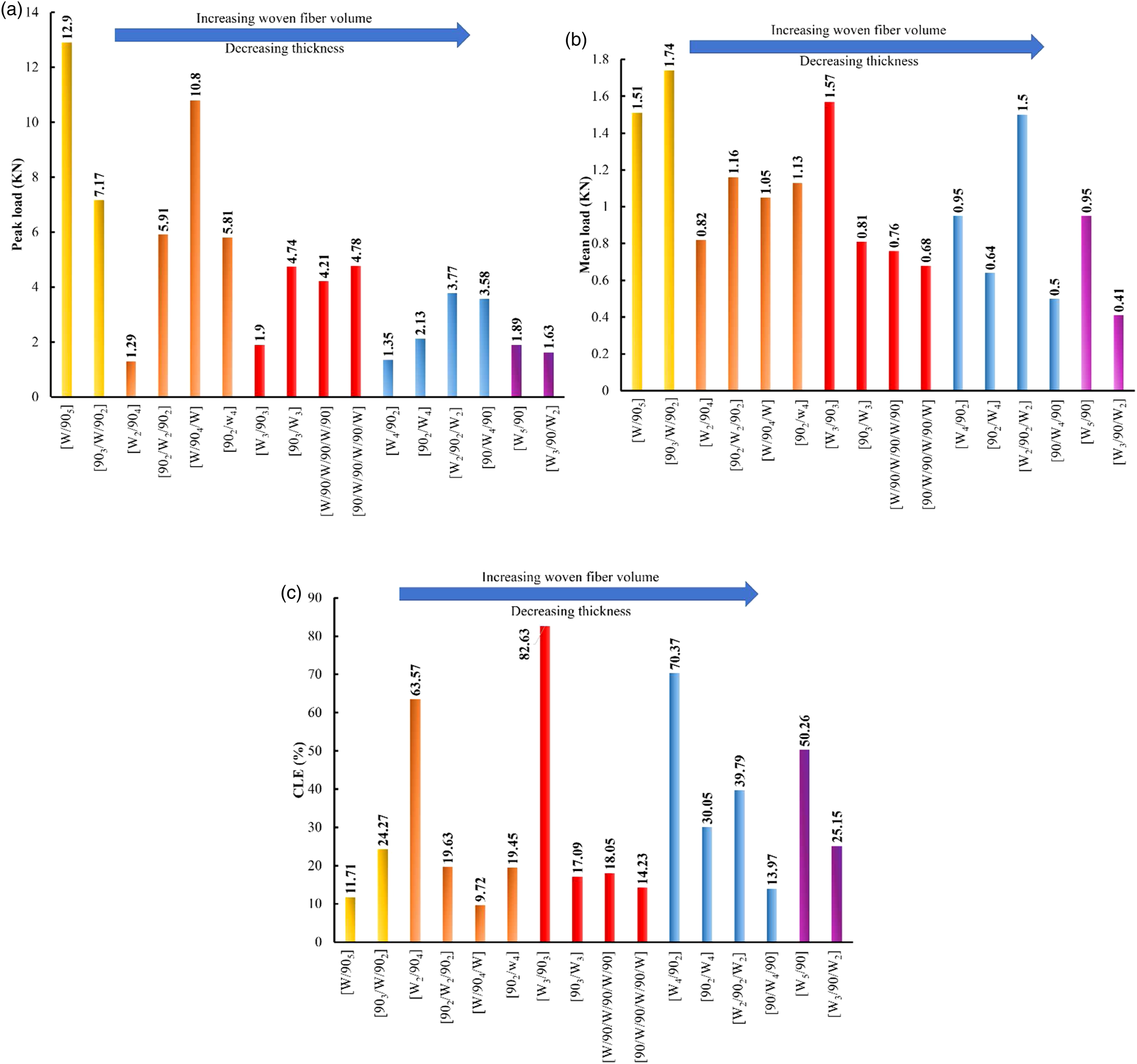
Tubes containing 66.6% woven fiber, and increasing in peak load up to 76.99% were observed where the amount of peak load for the [W2/902/W2] and [90/W4/90] samples was higher than for sample [W4/902] and [902/W4]. Now, according to the mean load values in Figure 18 (b), the CLE value for the sample [W4/902] was higher than the other three stacking sequences. For samples consisting of 83.4% woven fibers, the mean load of [W5/90] was 56.84% higher than the other sample, as well as the CLE.
The comparisons made in this section suggest that the placement of woven fibers next to each other in the inner layers of the composite tube causes the CLE to tend to ratio of 1. In other words, the higher the ratio of the volume fraction of W fibers to UD, the higher the CLE value.
Conclusion
Designing the wall structure of thin-walled composite tube inspiring from biological structures is a promising approach to obtain higher crashworthy properties and energy absorption capacity without sacrificing the weight efficiency. Since bamboo owns significant lateral and axial strength, mimicking its wall structure containing gradient distribution of vascular bundles helps to improve the crashworthiness of thin-walled composite tubes. Based on the gradient distribution of vascular structure and related dimensions, the organic matrix and vascular bundles were considered as plain woven with 0 and 90 fiber layup orientation in locations with more density of vascular bundles; besides, the organic matrix was considered as circumferential UD fibers in the place with lower density of vascular bundles. The reason of such considerations is manufacturing limitations. But by considering the longitudinal vascular bundles as axial UD fiber and organic matrix as circumferential UD fibers, seven different types of bio-inspired tubular composite energy absorbents comprising seven different layers of UD and woven glass fiber were fabricated by a modified hand layering up method. The manufacturing process introduced in this study provides higher production rate and the flexibility for fabricating small radius cylindrical tubes which are limited by the high flexural strength of UD glass fibers through the 0-and 90-degree directions. Besides, applying mechanical pressure on wrapped tubes incorporated with utilizing Dacron sheets improved the surface finishing and interlaminar adhesion of bio-inspired composite tubes. According to the fabrication criteria and crashworthiness parameters, it was concluded that the tubes consisting of inner woven and circumferential UD fibers show superior crashworthiness in performance. Hence, the [FW3/903] layering configuration provided the best crush performance close to middle layers of bamboo wall structure.
The crashworthiness parameters of composite tubes are related according to layering configuration schemes. A numerical model of composite layers is treated as a single distinct layer and its failure strength in the circumferential and axial directions are calculated by the Chang-Chang criteria. In addition, to validate the model, predicted values for the mean crushing load, peak load, and the crush failure modes corresponding to [FW3/903], [FW2/904] and [FW4/902] stacking sequences are compared with experiments and the results show reasonably good agreement. In order to investigate different distributions of vascular bundles amine organic matrix corresponding to the wall structure of bamboo, the validated FE model was developed and different combinations of fine woven and circumferential UD fibers were analyzed. The following conclusions may be drawn: 1. In the aspect of crushing failure mode, the [FW]6, [CW]6, [FW2/904], and [FW4/902] tubes were crushed in the catastrophic failure mode, while in [FW3/903], [CW3/903] stable progressive crushing mode was the dominant failure mode. Besides, in the case of [902/02/902] stacking sequences up to 30% of the length of tube suffered progressive crushing followed by the generation of a circumferential crack in the bottom of the tube which caused catastrophic failure. 2. Considering the manufacturing process limitation for high modulus UD glass fibers, obtained SEA and CLE values, and post crush integrity, [FW3/903] seems to be the best candidate. In the [902/02/902] stacking sequences poor interlaminar adhesion and manufacturing quality was resulted, due to the bending resistance of UD fibers during the wrapping process. Although the [CW3/903] specimen showed progressive crushing failure mode, the poor interlaminar adhesion was observed due to the bending resistant of 90-degree fiber in plain coarse woven alongside with circumferential UD fibers. This phenomenon led to forming irregular internal and external fronds and low number of interlaminar and intralaminar cracks. 3. The numerical parametric study presented that the dominant crushing modes of the hybrid FW/UD tubes were determined by the types of UD fiber location in the circumferential direction of the tubes. It was observed that the placement of UD fibers over woven fiber and composing equal number of woven and UD layers provides higher values of SEA. On the other hand, regardless to the location and conjunction of woven fibers, the equal number of woven and UD fibers presented the progressive crushing failure modes resulted to achieve higher crush length efficiency. Besides, the placement of woven fibers next to each other in the inner part of the part of the wall structure of bio-inspired composite tube caused the CLE values increased up to the ration of 1.
Footnotes
Author contributions
Amirreza Tarafdar: Conceptualization, Methodology, Software, Validation, Formal analysis, Investigation, Resources, Data Curation, Writing - Original Draft, Writing - Review and Editing, Visualization.Omid Razmkhah: Review and Editing.Hamed Ahmadi: Review and Editing.Gholamhossein Liaghat: Conceptualization, Review and Editing, Supervision, Project administration.Sahand Chitsaz Charandabi: Review and Editing.Moslem Rezaei Faraz: Review and Editing.
Declaration of conflicting interests
The author(s) declared no potential conflicts of interest with respect to the research, authorship, and/or publication of this article.
Funding
The author(s) received no financial support for the research, authorship, and/or publication of this article.