
Abstract
While around 60% of pipelines transmitting oil and gas worldwide experience corrosion and metal loss, the composite repair technique has become a popular option developed in recent decades. Employing a theoretical methodology, this study deals with corroded metallic pipes repaired by composite repair systems such that the focus is the impact of elastoplastic deformations on the failure pressure. In this methodology, the elastoplastic strains are taken into account by employing the bilinear isotropic hardening plastic flow theory with the von Mises yield criterion. Three modes are recognized based on the region where failure occurs, and the results are presented. The findings revealed that when the failure happens in the defect region, the proposed formula estimates the failure pressure more accurately than when it occurs either far from the defect or in the composite sleeve. Moreover, studying the bonding strength between the pipe, infill material, and composite patch shows that the interface bonding strength between the pipe and the polymer filler plays a more significant role than the interface bonding strength between the polymer filler and the composite repair. The results of this study can assist maintenance engineers in better evaluating the reliability of composite repaired pipelines.
Introduction
Pipelines are still substantial primary operations for conveying fluids like hydrocarbon productions, water, and urban sewage. 1 Until now, metallic pipes have been used to carry oil and gas since the 1940s and 1950s; however, this results in aging and catastrophic failure. Nonetheless, buried or submerged steel pipes may operate under adverse deterioration in the form of cracks, corrosion, dents, wearing, gouging, spalling, buckling, leaks, and rupture. The most common imperfections of steel pipes are corrosion and metal loss. 2 The global cost of corrosion is annually expected to exceed $1.8 trillion. 3
If the pipe experiences severe corrosion, the defected segment should be replaced by a new specimen. Another repair method employed to repair gas pipelines is hot tapping, but it is not a safe treatment also demands high skill. Rehabilitating with metallic sleeves is also an accepted practice that can be applied based on standards similar to ASME PCC-2. Nevertheless, heavy metallic clamps need welding to be implemented. Besides, it does not have proper access to damaged subsea pipelines and risers that need rehabilitation. Hence, there has been an increasing demand for a novel repair technique with high safety, suitable strength, low costs, etc. Recently, applying composite materials for repairing damaged pipes, the expenses have decreased by 24% and 73% instead of using metallic sleeves and replacing them with a new part, respectively. 4 After considering composite materials to repair, various composite repair systems, including flexible wet lay-up, pre-cured layered system, pre-impregnated system, split composite sleeve system, and flexible tape system, were provided. 5 However, great attention is still given by researchers to study different features of composite repair systems. Although various types of fiber-reinforced composite repair systems commercially exist, the fundamental concept of the rehabilitation plan is similar. Its idea is to carry the stress in the pipe wall due to loadings to the composite sleeve.
Substantial pieces of research have recently looked through the performance of composite materials for rehabilitating either corroded or cracked pipelines. Bezzerrouki et al. 6 studied a metallic pipe with a through-wall circumferential crack repaired by glass/epoxy material under a traction effect. Benziane et al. 7 investigated a metallic pipe suffering from a longitudinal through-wall crack repaired by a carbon epoxy composite sleeve employing FE analysis. Chan et al. 8 put forward the impact of composite layers’ alignment on the bending moment capacity of a corroded metallic riser rehabilitated by fiber-reinforced polymer composites. Saeed et al. 9 focused on the reliability of composite repaired pipes using statistical techniques. Additionally, several experimental studies examined composite wrap and infill material properties. Preliminary tests conducted by Lim et al. 10 reported that applying a pre-impregnated FRP composite wrap has improved the failure pressure of the defected pipe by 23%; however, strains in the damaged region significantly decreased. Freire et al. 11 conducted hydrostatic tests for 14 API X60 defected specimens, where 11 of them were repaired by the four types of composite materials. Duel et al. 12 investigated the influence of defect length in the circumferential direction on the internal pressure capacity of a metallic pipe with an external defect restored by woven carbon-reinforced epoxy, using both hydrostatic tests and FE analysis. Bruere et al. 13 predicted the failure of the pipe with multiple corrosion under combined internal pressure and the axial compressive force using FEM. A study conducted by Mazurkiewicz et al. 14 showed that if the local wall thickness of a hot-rolled steel pipe is markedly reduced from 6 mm to 2.4 mm, the failure pressure would fall up to 40%. Nonetheless, fiberglass can enhance the strength of a damaged pipe, overtaking a non-corroded pipe strength. Conducting both four-point bending and hydrostatic tests, McCready et al. 15 assessed the performance of a composite repair system applied to a metallic pipe subjected to either localized or axisymmetric defect types. Sing et al. 16 examined the excellent mechanical properties of infill materials used to fill a localized defect in the metallic pipe through laboratory tests and FEM. Khan et al. 17 reported that the restoration of damaged pipelines using glass epoxy composites with nano clay reinforcement improves the interfacial bonding strength between the pipe substrate and repair sleeve, and subsequently increases the internal pressure capacity of the reinforced pipe. A FE study presented by Shadlou and Taheri, 18 investigating the impact of both partial and perfect bonding conditions in the pipe/composite interface, revealed that interface condition does not have a substantial influence on bearing combined bending moment and internal pressure loading conditions.
Last but not least, employing theoretical methods, some studies have been performed to give a better prediction of internal pressure capacity; however, most of them did not address the performance of theoretical predictions considering the type of failure mode and stress distribution. Sirimanna et al. 19 investigated the various levels of bonding of internal composite liners used to repair a metallic pipe suffering from an axisymmetric defect employing Lame’s solution. Costa-Mattos et al. 20 provided a simple methodology for predicting the failure pressure of a reinforced metallic pipe suffering from any type of corrosion repaired by any kind of composite repairs. The suggestion was that future studies put forward the plastic deformations of the metallic pipe during failure, the pipe’s axial strains, and thick-walled composite repairs. Budhe et al. 21 studied the effect of polymer filler between an externally corroded metallic pipe and a composite repair system applying a simple theoretical methodology validated against the conducted hydrostatic test. Assuming the metallic pipe is an elastic cylinder, the predicted pressure was conservative compared to both laboratory tests and ISO/TS 24817 standard. They stated that the metallic pipe shows a plastic deformation far away from the metal loss region. Hence, such an issue needs further investigations for a more accurate suggestion of the maximum permissible pressure. The recent papers have involved several assumptions to obtain a simple expression. The pipe was supposed to be an open-end, and the axial stresses were neglected. The plastic deformations existing away from the defected area were excluded; however, experimental tests report on considerable plastic deformations outside the repaired region. 22
The present study intends to focus on those details omitted in earlier investigations to prepare a better piece of knowledge on composite repaired pipes. The plastic deformations of the metallic pipe existing outside the corroded region are considered. Moreover, the axial stresses in the pipe ends are included. The mechanical effects of the interface bonding conditions between the pipe, the polymer filler, and the composite repair are also studied. The metallic pipe contains localized corrosion damage on the external surface. Depending on whether the failure occurs in the pipe or the composite repair system, the failure pressure is obtained. Two approaches are employed to simulate the pipe defect. The first one includes a damage factor, but the second one assumes an axisymmetric defect filled by a filler. The study starts with the fundamental theories of elastoplastic pipes and elastic composite wraps, modified to evaluate the failure pressure of a defective tube reinforced by a composite sleeve. The predicted failure pressures obtained by the introduced methodology are validated against the experimental data reported in the literature employing various standard criteria. The finite element method is also carried out further to study the failure behavior of the repaired pipes.
Several considerations are included to make the theoretical procedure more convenient. If the wall thickness-to-diameter ratio is less than 1/10 internal radius for a pipe, it can be regarded as a thin-walled cylinder.
23
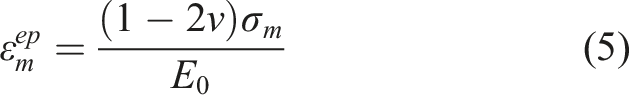
Such an assumption is usually acceptable for pipelines having large diameters, which are utilized in the oil and gas industry. Assuming the pipe is a thin-walled structure, the stress component in the radial direction is negligible. Therefore, the axial stress
Theoretical methodology
Assume a metallic pipe with an external wall loss defect has been repaired by a composite sleeve under internal pressure loading. Regarding the steel pipe and the composite sleeve as a thin-walled elastoplastic cylinder and a thick-walled elastic orthotropic cylinder, respectively, the basic equations are expressed in the following.
Thin-walled elastoplastic cylinder
Based on the theory of small elastoplastic deformations,
26
the expressions of the relationship between the stress and the strain components in longitudinal and circumferential directions are as follows
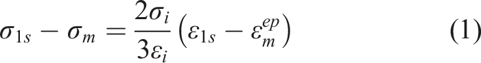
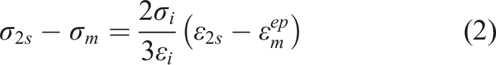

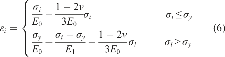
Based on the theory of the universal stress-strain curve and using an approximation of bilinear hardening to express the relation of uniaxial stress and uniaxial strain, the relationship between strain intensity and stress intensity becomes
Thick-walled elastic orthotropic cylinder
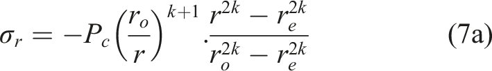
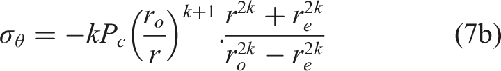
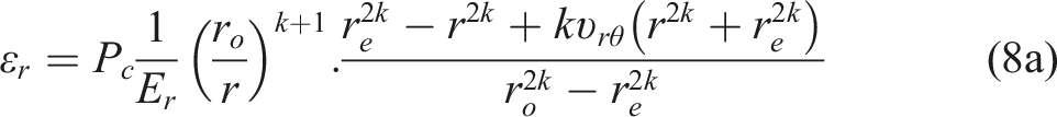
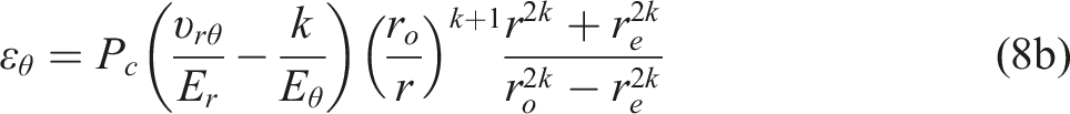
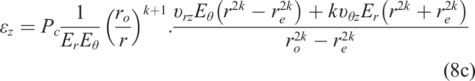
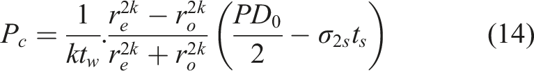
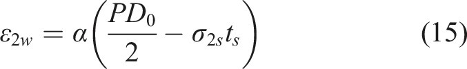
To model the composite sleeve as a thick-walled orthotropic cylinder, the contact pressure acting between the metallic pipe and the composite wrap applied in the internal surface of the composite wrap is
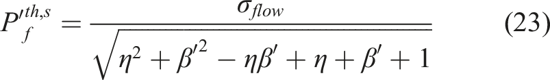
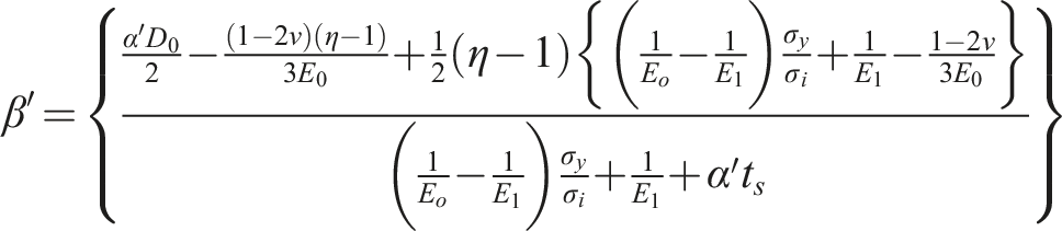
Failure pressure of a composite repaired pipe
The present section is concerned with the metallic pipeline with an external wall loss defect repaired by a composite wrap. Assuming the pipe and the composite repair as two concentric cylinders, the main idea is that the composite sleeve reinforces the pipe by applying a contact pressure (i.e., P c ) on the external surface of the pipe. Two methods employed to examine the effect of the corroded region including the damage factor approach and the so-called non-damage factor approach (NDFA) are represented in the following.
Damage factor approach
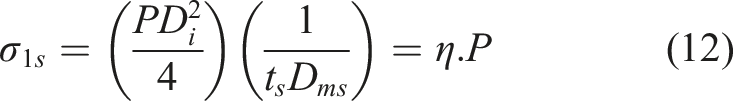
Practically, the corroded region is a localized defect. After cleaning the outside surface of the pipe, the external corrosion is filled with an infill material, which is subsequently strengthened by a composite sleeve, as shown in Figure 1. The reinforcement generates a contact pressure on the pipe’s surface; consequently, it improves the pipe’s internal pressure capacity by decreasing stresses and strains. The required strain components for the steel pipe are Pipe repairing process based on the damage factor approach.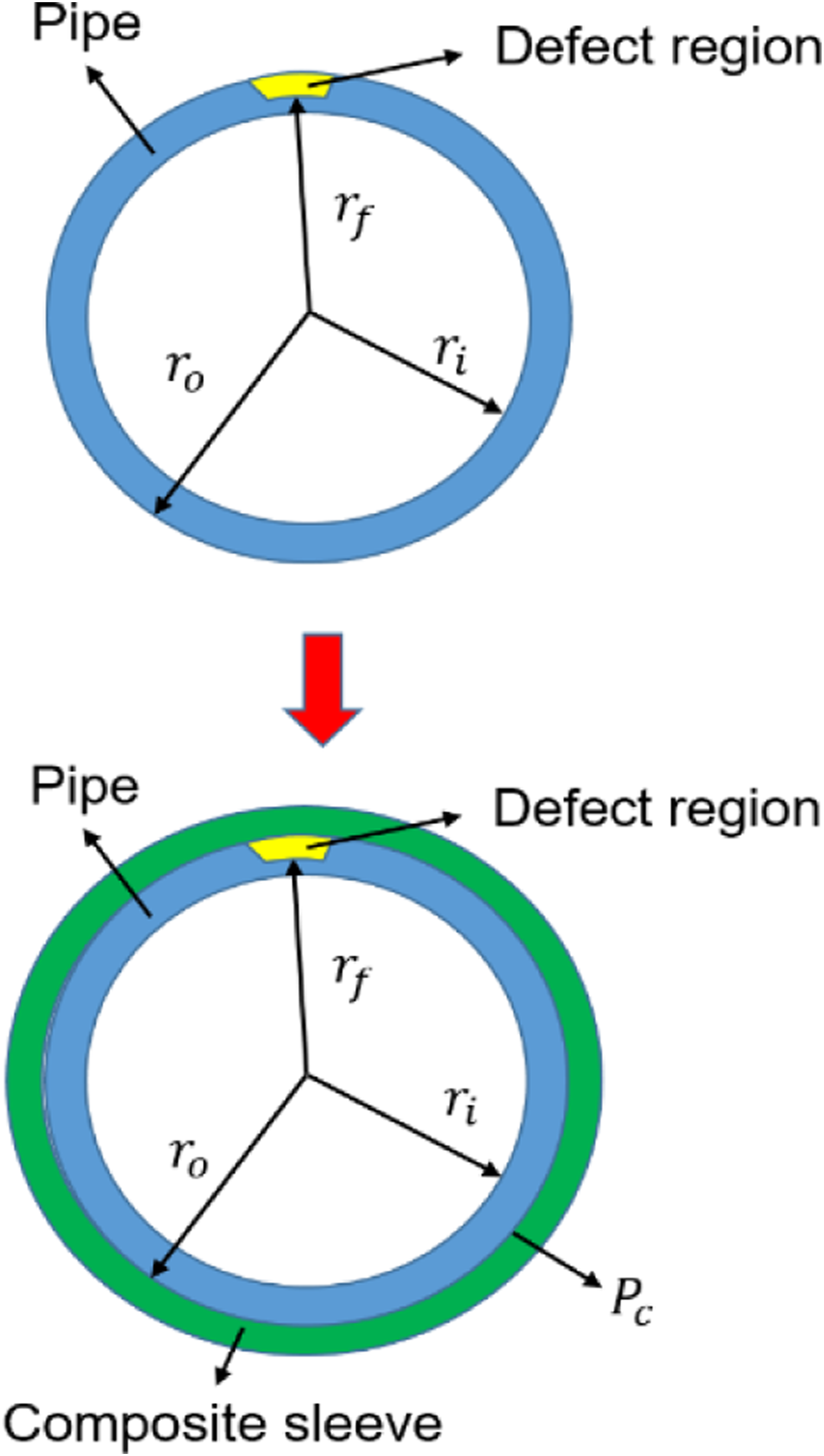

Using the essential theories explained in Thin-walled elastoplastic cylinder and Thick-walled elastic orthotropic cylinder, the metallic pipe and composite sleeve are considered with elastoplastic and elastic deformations, respectively. Consider a metallic pipe with an inside radius

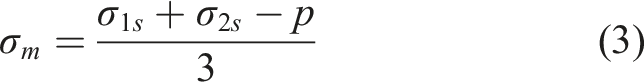
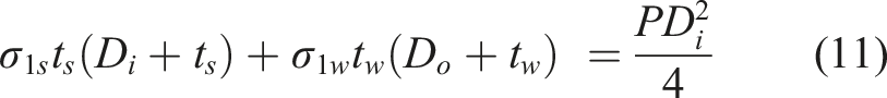
Regarding a pipe with the elliptical end plugs subjected to internal pressure loading, the balance equation in the longitudinal direction can be written as
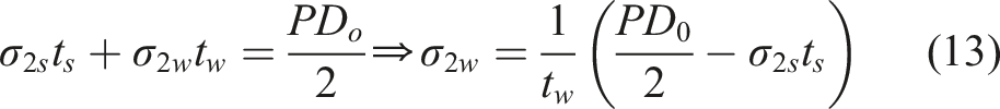
Using equations (7b) and (13),
Substituting

In the next step, the damage factor
Introducing
After calculating
Non-damage factor approach
This approach does not include the damage factor, but considering an axisymmetric defect instead of a localized one provides a geometrical effect equivalent to the damage factor.
21
As shown in Figure 2, the corrosion defect is not localized anymore but is extended to be an axisymmetric defect having that depth of the localized defect and the same width as the pipe. Filling this axisymmetric defect with an infill material provides a contact pressure P
c1
between the pipe and the applied filler. Finally, employing the composite sleeve on the external surface of the infill material, another contact pressure, P
c2
, is generated. Pipe repairing process based on the non-damage factor approach.
As we know, the partial bonding situation can occur during a period, resulting from the debonding or improper proficiency, leading to the weak bond of repair components. To simulate partially bonded conditions between the metallic pipe, polymer filler, and composite sleeve, two factors of


If
However, if the composite starts to break down before pipe failure, then pressure capacity is obtained by .
The lower value of
Finite element analysis
The FE analysis of an externally corroded pipe, repaired with a composite sleeve, was conducted within ANSYS Workbench 18.2 to support the internal pressure capacity predicted by the theoretical study. Firstly, the model is validated against the hydrostatic burst test of a non-reinforced pipe with an external defect presented in Ref 11. For this model, the pipe is made from API 5L X60. The pipe’s yield strength, ultimate strength, Young’s modulus, and Poisson’s ratio are 413 MPa, 627 MPa, 210 GPa, and 0.3, respectively. The pipe’s outer diameter, thickness, and length are 508 mm, 14.3 mm, and 3 m, respectively. The rectangular defect has 97 mm width in the circumferential direction, 500 mm length in the longitudinal direction, and 10 mm depth in the external surface of pipe. In the next step, the finite element model of the composite repaired pipe is simulated. The model consists of the metallic pipe, polymer filler, and composite sleeve. Fixed radius blends of 12 mm and 50 mm were applied at the axial and tangential directions of the defect’s edges, respectively, to decrease stress concentration in sharp corners. Modeling the external corrosion as a rectangular defect with fillers along both circumferential and longitudinal directions provides the advantage of removing stress concentration in corners.
32
The geometry components are sliced into several sweepable bodies to implement a mesh having sufficient quality. Taking sweep meshing function in ANSYS Workbench, the model was meshed by the Solid-186 element wherever possible. It is a higher order 3-D 20-node solid element showing quadratic displacement behavior, with each node having three degrees of freedom.
33
Additionally, the quality of the mesh was investigated by the orthogonal quality of elements and their skewness.
34
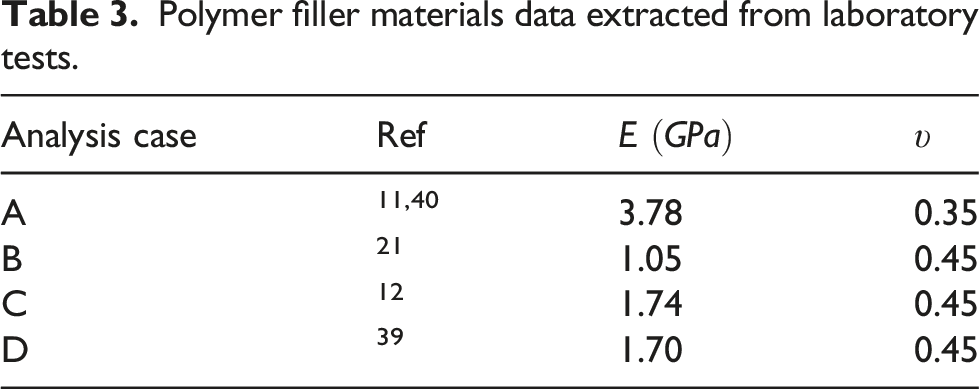
A remote point was firstly created in the pipe’s end to apply boundary conditions, and then a remote displacement object is subjected to this point. All the degrees of freedom at the created remote point are removed to avoid rigid body motion and simulate the laboratory hydrostatic test conditions. A non-slip, perfect bonding, surface-to-surface contact condition was defined as the interaction between the model components. In the practical application of composite repair systems, the diversity in material categories and installation procedures may lead to poor bonding between the elements. Nevertheless, a non-slip perfect bonding assumption has been implemented in several numerical investigations,6,8,35–38 leading to a cooperative agreement with the experimental data and a significant decrease in simulation expenses. One composite patch layer with the equivalent repair thickness is only applied according to a perfect bonding assumption and the proposed theoretical approach. Using the advantage of symmetric geometry and loading conditions, a quarter of the geometry was only constructed to reduce the computational time. Moreover, a constant pressure loading condition was incrementally applied at the internal surface of the pipe. Employing various recent experimental studies,11,12,21,39,40 several FE models are made to assure that the findings are reliable and to diminish the probability of manipulation. Similar to the theoretical section, in all cases, the stress-strain constitutive relationship employing a bilinear isotropic hardening material curve was applied to the metallic pipe. The polymer filler and the composite repair were modeled by elastic isotropic and orthotropic constitutive laws, respectively. Considering several implemented models, mesh convergence studies were conducted to establish an optimum mesh with sufficient accuracy. An average of 18,617 elements connected by 79,056 nodes were adopted to generate FE models. Figure 3 shows the schematic of a typical FE mesh and boundary conditions used in the current study. The required properties to model the metallic pipe, polymer filler, and composite sleeve are listed in Table 1, Table 2, and Table 3, in turn. Different FE analyses have been simulated using Refs. 11, 12, 21, 39, and 40, where model A consists of nine cases having variations in either material or geometrical properties. In three models, including A, B, and C, the repair length has not been specified, and so equation (25) based on the ASME PCC-2 is employed as follows
41
Characteristics of a typical simulated finite element model: (a) FE mesh and (b) boundary conditions. Defective pipes data extracted from laboratory tests. Composite repairs data extracted from laboratory tests. Polymer filler materials data extracted from laboratory tests.

In equation (25),
Results and discussion
The von Mises contour for the case of the non-repaired pipe shows that the maximum equivalent stress occurs in the defected area. The internal pressure rises incrementally, and the maximum von Mises stress is checked. There is a point in which the ANSYS solver cannot solve the finite element model. At this point, some of the elements are highly distorted due to the high loading value, and so it is regarded as the failure point. Figure 4 shows that the failure occurs in the defect region of the pipe, representing the highest equivalent von Mises stress in this area. The experimental and numerical burst pressure values are 14.6
11
and 13.1 MPa, respectively, meaning a 10.27% relative error. Therefore, the finite element model has been verified and can be used for further investigations in the composite repaired pipes. Classifying the overall response of the repaired pipe in three modes, the results are presented in the following. Non-repaired pipe failure: (a) Experimental test
11
and (b) the von Mises stress from FE analysis. Repaired pipe failure after taking off the reinforcement considered as Mode I: (a) Experimental test
11
and (b) the von Mises stress from FE analysis.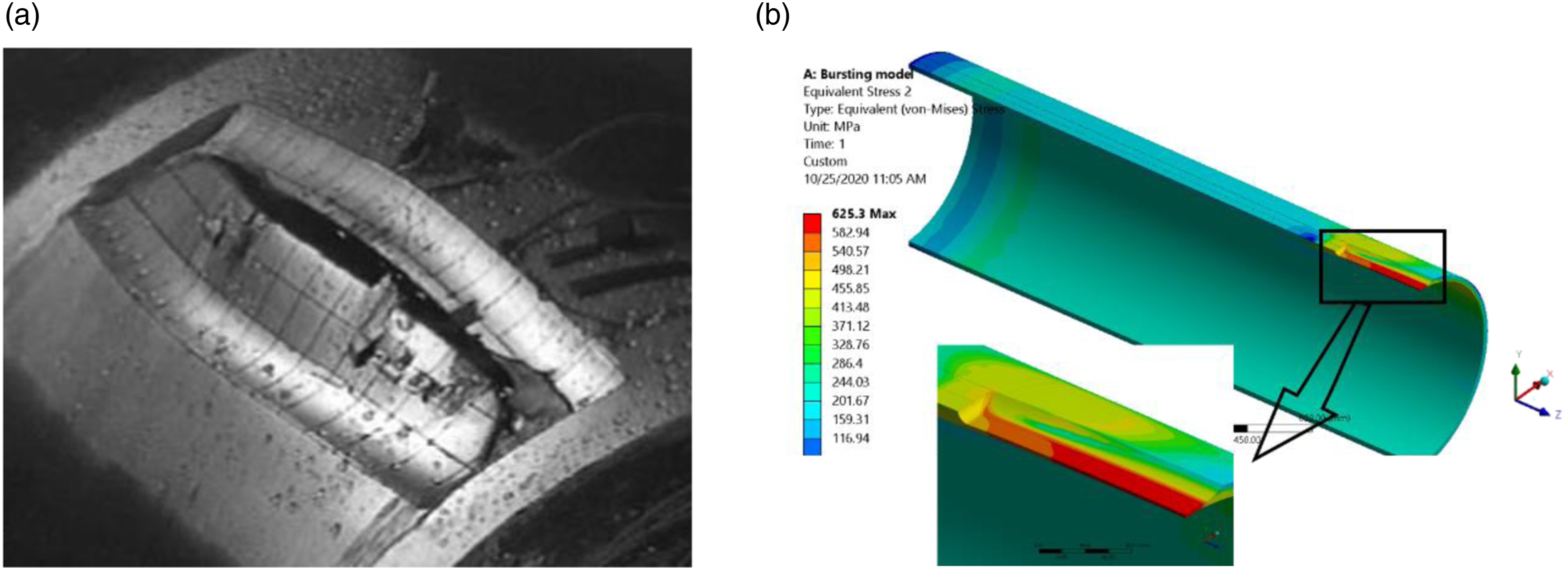
Mode I
Failure pressure estimations in Mode I (MPa).
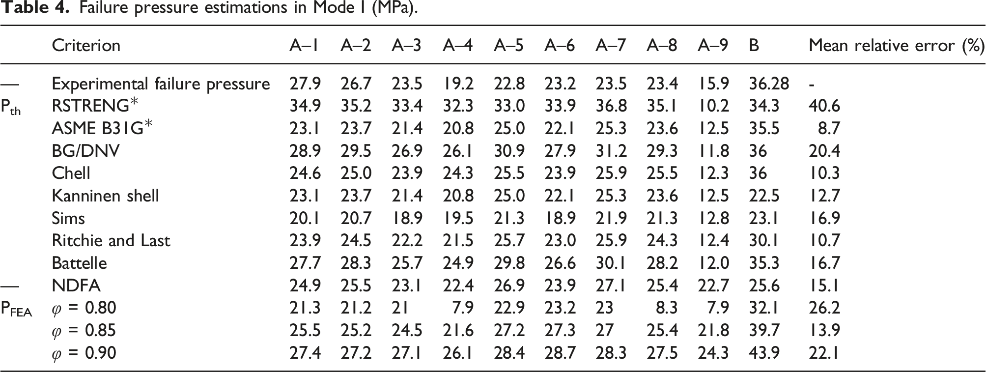
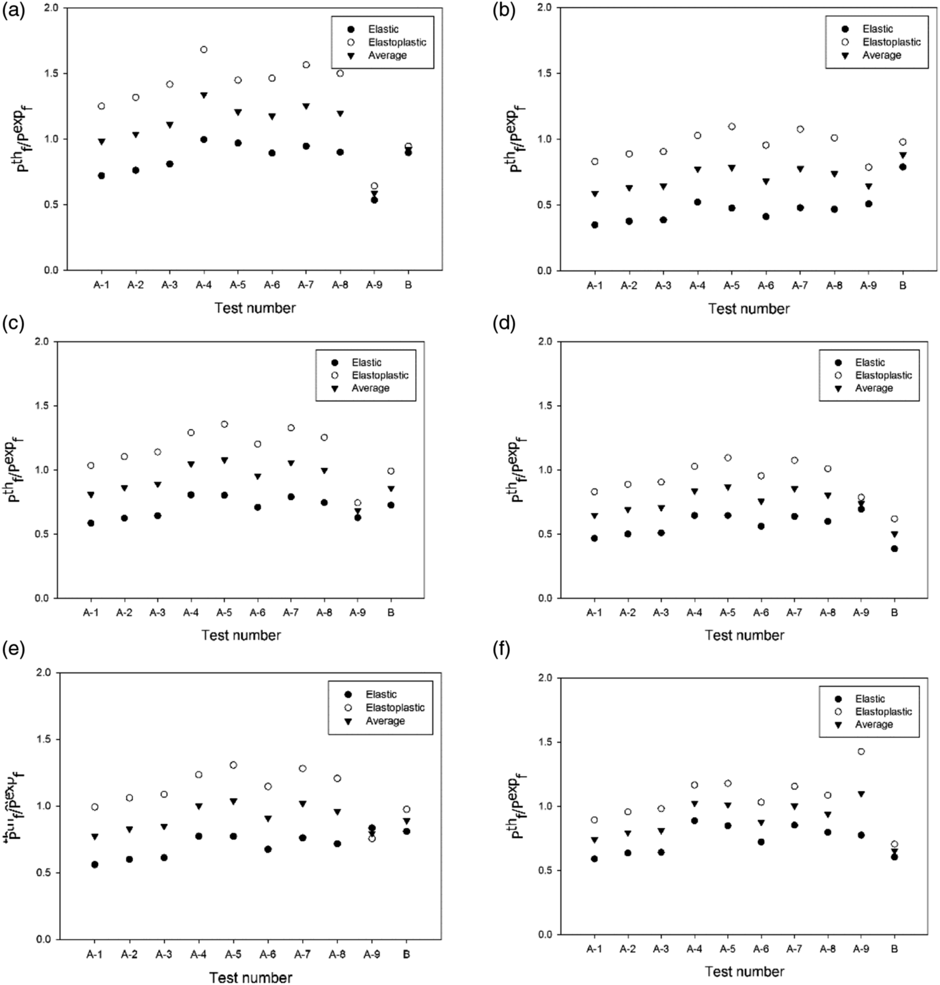
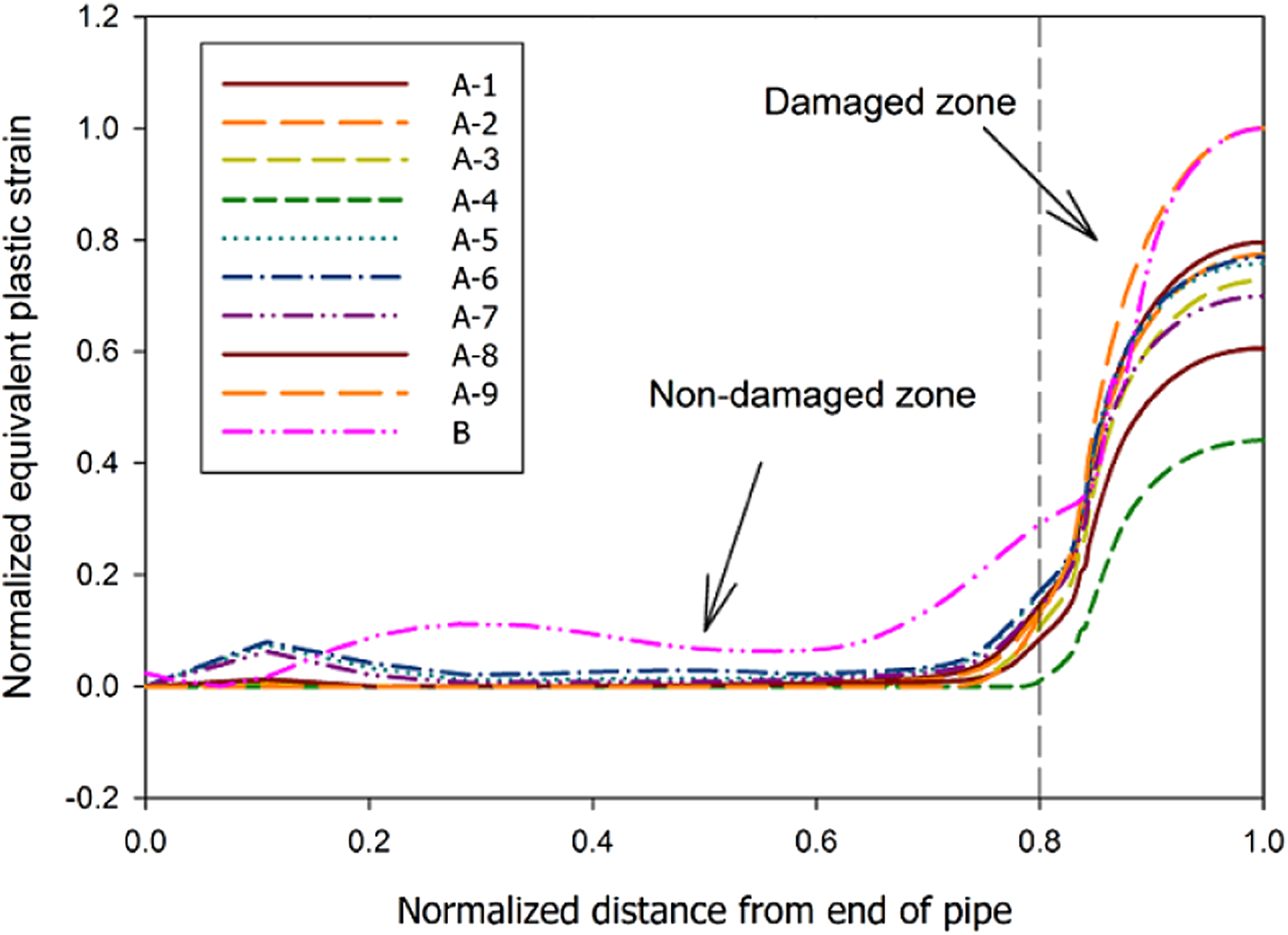
Figure 7 depicts the effect of various levels of partially bonded conditions on the failure pressure for the first mode. If The effect of bonding factors The relationship between the normalized equivalent plastic strain and normalized distance from the end of the pipe in Mode I.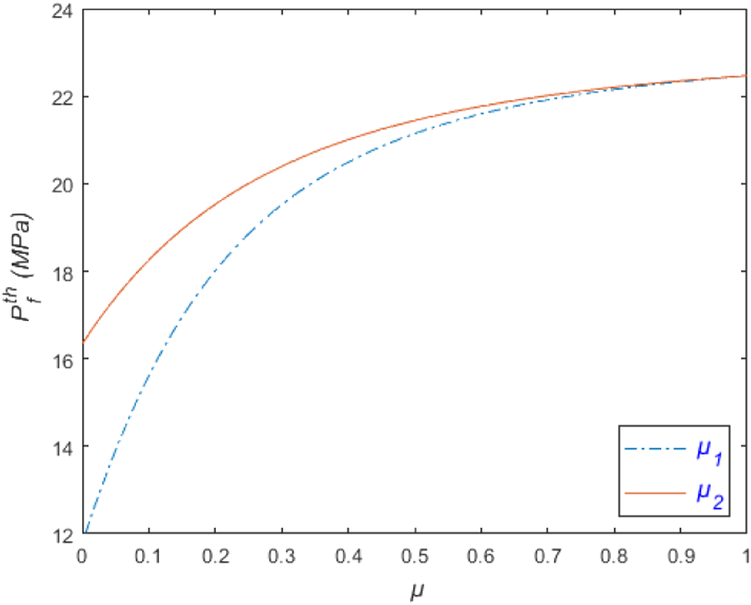
Mode II
According to Ref. 12, in the associated FEA simulation (model C), the repaired pipe can be thought to be failed if the equivalent von Mises stress in the steel pipe exceeds the ultimate tensile strength Circumferential stress distributed at the center of the defect from the inside of the pipe wall to the outside of the composite sleeve at failure pressure. Failure pressure estimations in Mode II (MPa).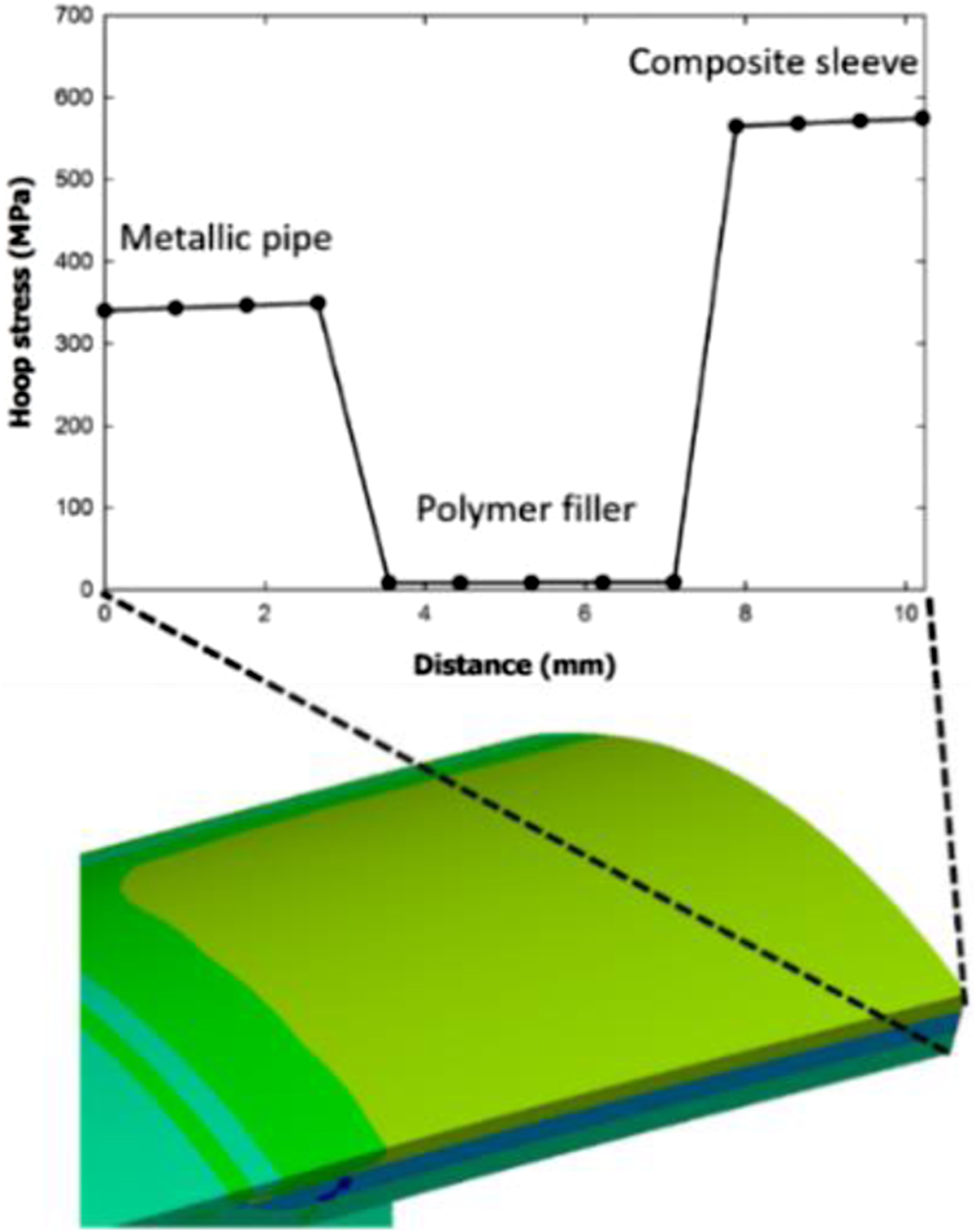
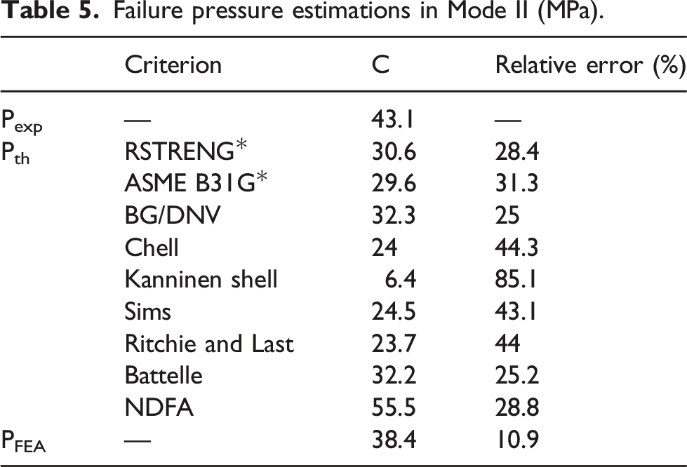
Moreover, Figure 10 presents the theoretical results for all criteria using elastic and elastoplastic assumptions and also the average of their predicted values. It can be witnessed that ASME B31G, BG/DNV, and RSTRENG* criteria give the best results for elastic, elastoplastic, and average cases whose error is 2.0%, 25.0%, and 20.0%, respectively. The theoretical results for all criteria in Mode II.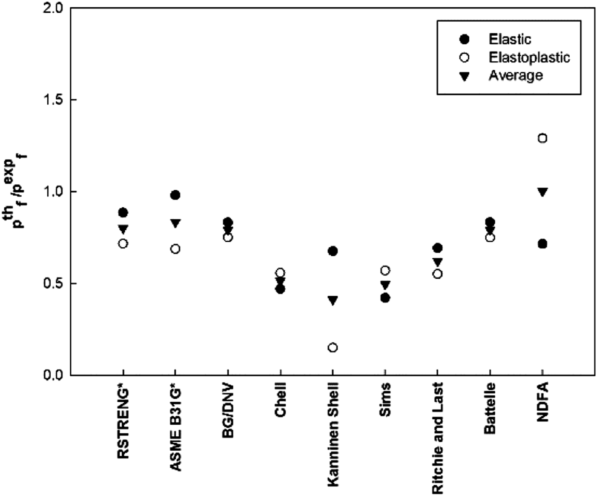
Figure 11 represents the effect of various levels of the partially bonded factor on the failure pressure for Mode II. By comparing Figure 7 and Figure 11, the first and second modes account for the same trend. However, the interface bonding factor affects the failure pressure of the former further than the latter. The effect of bonded factors 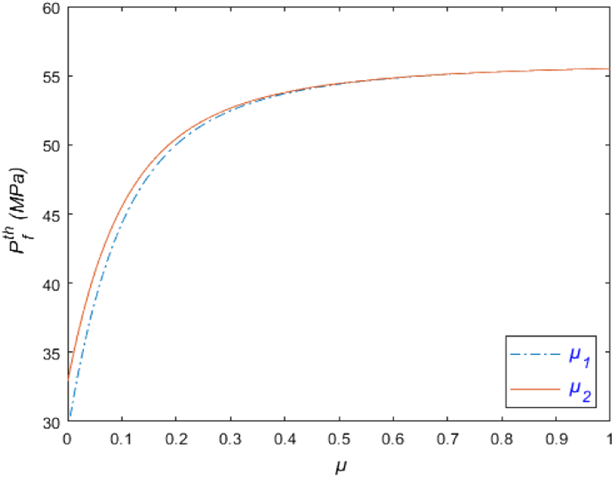
In contrast to Mode I, Figure 12 represents that the highest plastic strain occurs outside the defect zone, dipping substantially in the defected area. Consequently, in this mode, the composite sleeve breaks initially, and then the metallic pipe highly deforms, and finally, the pipe fails in the corroded zone. The relationship between the normalized equivalent plastic strain and normalized distance from the end of the pipe in Mode II.
Mode III
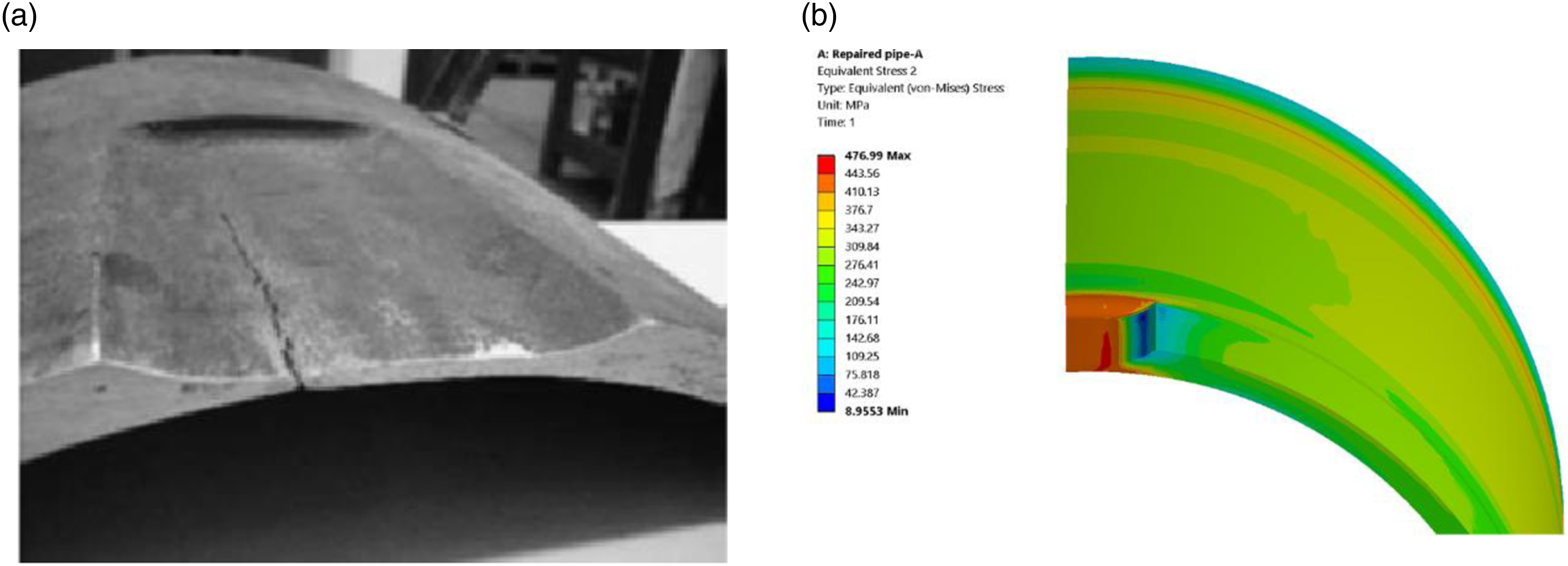
In the third mode, the composite wrap can effectively rehabilitate the damaged pipe, and accordingly, the rupture occurs away from the repaired area. So, the criterion for failure is that the equivalent von Mises stress in the pipe wall reaches its ultimate tensile strength. Considering such a criterion, the FE result of model D depicted in Figure 13 can suitably predict the experimental failure mode. A comparison of estimated pressure values between the proposed theoretical methodology, experimental test, and FE model, as tabulated in Table 6, reveals that RSTRENG* gives the best output using the elastoplastic hypothesis with 8.1% relative error. Repaired pipe failure in Mode III—(a) experimental test 39 and (b) the von Mises stress from FE analysis. Failure pressure estimations in Mode III (MPa).
Figure 14 shows that the results obtained by either the elastic or average theory cannot suitably predict the experimental failure pressure. One potential cause is that the elastic behavior of the pipe far from the defect gives a conservative failure prediction; however, when the pipe behavior is assumed to be elastoplastic, the accumulated strain outside the pipe defect is also included. There is a significant difference between the response of pipe in the second and third modes. In the second mode, hoop stresses in the composite sleeve reach the composite’s ultimate strength, and then the equivalent von Mises stress in the pipe hits its ultimate tensile strength; however, the opposite is true for the third mode. As shown in Figure 14, the results obtained by the NDFA in the three hypotheses are close together. The reason why is that when the failure occurs, the plastic deformations are relatively small in the defect region; however, the NDFA assumes that maximum deformation exists in the metal loss region. The influence of partially bonded conditions on the internal pressure capacity in the third mode is observed in Figure 15. As might be expected, as the failure occurs away from the damaged zone, the interface bonding strength between the pipe-filler has a negligible impact on the failure pressure. The theoretical results for all criteria in Mode III. The effect of bonded factors 
Also, according to Figure 16, the maximum equivalent plastic strain in this mode is observed outside the defect zone, representing the similarity to the pipe behavior in the second mode. Hence, one potential cause for the specimen failure outside the reinforced section is that the equivalent stress and strain components take their maximum values in that region. The relationship between the normalized equivalent plastic strain and normalized distance from the end of the pipe in Mode III.
Conclusions
The present article suggests a theoretical methodology to achieve the failure pressure of an externally corroded, thin-walled metallic pipe strengthened with polymer-based composite repair systems. The main results are briefed in the following: 1. Classifying the failure conditions into three modes based on the breakdown shows that the theoretical failure prediction depends significantly on the failure mode. 2. When the damage factor and the plastic deformations are included, the estimations are overestimated, but they are underestimated when the plastic deformations are neglected. Considering the average results obtained by the elastic and elastoplastic assumptions, the first mode presents the best failure prediction value using the Battelle criterion. 3. The FE analysis was also carried out compared with the proposed theoretical methodology. In the first mode, the obtained failure criterion is that the equivalent stress over the defected ligament reaches 0.85 portions of the ultimate tensile strength. In the second mode, the best prediction is achieved when the hoop stress in the composite is equal to its maximum tensile stress. Finally, in the third mode, the failure occurs so that the equivalent von Mises stress reaches the pipe’s ultimate tensile strength. Considering all the FE results, the FE model in the second mode gives the closest pressure prediction to the experimental test. 4. Studying the presence of the filler between the pipe and composite sleeve shows that the interface bonding strength between the pipe-filler plays a significant role in the predicted failure pressure. Further investigations are required to provide a better understanding of the performance of a composite repair system employing bonding factors between the layers and their directions. 5. Although various articles put forward the reliability of corroded pipes, there is still a lack of sufficient studies toward the reliability of composite repaired pipelines, concentrating on elastoplastic strains and partially bonded conditions. The proposed theoretical methodology can conveniently be employed as a limit state function to study the reliability of repaired pipes in future studies. The sensitivity analysis would reveal the impact of the partially bonded conditions and elastoplastic deformations on failure pressure regarding the uncertainty of input parameters.
Footnotes
Declaration of conflicting interests
The author(s) declared no potential conflicts of interest with respect to the research, authorship, and/or publication of this article.
Funding
The author(s) received no financial support for the research, authorship, and/or publication of this article.
Appendix A Burst strength models of corroded pipes 28 – 30
Criterion
RSTRENG*
ASME B31G*
1.1
BG/DNV
Chell
1.1
Sims
Ritchie and last
0.9
Battelle
Kanninen shell theory criterion
Normal stress components in steel pipe
Normal strain components in steel pipe
Normal strain components in composite sleeve
Axial and tangential strain components in the composite wrap
Axial and tangential strain components in filler
Pipe elasticity modulus
Pipe tangent modulus
Pipe yield strength
Pipe ultimate tensile strength
Pipe flow stress
Composite elasticity moduli
Composite wrap hoop ultimate strength
Composite wrap radial ultimate strength
Pipe inside and outside radii
Internal radius of the filler
The external radius of the composite sleeve
Contact pressure
Pipe, filler, and composite thicknesses
Pipe inside and outside diameters
Mean pipe diameter
Damage factor
Bonding factor between pipe and filler
Bonding factor between filler and composite
NDFA
Non-damage factor approach
Defect, taper, and composite axial lengths