
Abstract
The study focuses on the development of novel composite material with good transverse thermal conductivity able to dissipate the heat. This material will be associated with a cooling loop for transferring the heat from electrical equipment to the composite panel thermally drained and which posed at the fuselage of the aircraft. To achieve this goal, an extensive research was conducted in the thermal field leading to design a novel composite structure. The thermal conductivity of the composite materials selected in this work were assessed through experimental tests. Here, the material thermal conductivity was evaluated using measurements of density, thermal diffusivity, and specific heat. The thermal performances of material were described by the nature of constituents and reinforcement architecture. The current research highlights the influence of adding nickel coated carbon and nickel-plated copper wires on the braided composites. The results indicate that the High Tensile Strength (HTS) carbon braided manufactured with nickel-plated copper wires presents higher in-plane thermal conductivity (in direction parallel of the fibers) when comparing to HTS carbon and HTS carbon braided manufactured with nickel coated carbon. To gain more insight, a numerical model, based on the Finite Element Method was built. Besides, it helps to reduce the experimental matrix protocol. The results obtained by numerical and experimental investigation showed good correlation, which allowed to validate the numerical approach. In the end, the numerical model validated were used to optimize the structure of the composite material.
Introduction
Today, the systems and equipment used in aircraft flight are driven by hydraulic means, pneumatic or mechanical. These devices are representing a significant proportion of aircraft mass, which influence the fuel economy and generate operating costs and high maintenance. The concept of more electric aircraft is to reduce these inconvenient by using electromechanical actuators supplied by the power electronics. Apart, they can overcome the losses occurred at high temperatures, which can cause destruction of equipment. Thus, the thermal management is an important factor for electric actuation systems for future airplanes. The heat produced by electric actuators localized in the area around the motor and power electronics trigger a real problem. In order to guarantee normal operation of such electronic devices, efficient mechanisms for temperature control are necessary.1-4 Other5-7 have highlighted the thermal management issues for the electrical flight control actuators too. A new solution was proposed in the THERMELEC project in order to control the heat transfer. This is based in composite material thermally drained which contains a cooling loop for heat transferring from electrical equipment to the composite panel, as is presented in Figure 1. Cooling system.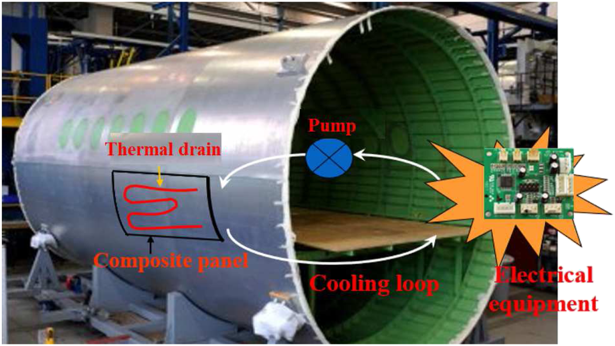
A literature review was conducted to identify possible solutions in terms of resin properties, fiber types, architecture, fiber volume fraction, and manufacturing technique. Requirements in terms of cost and availability of raw materials, light weight, compatibility with aviation standards were verified as well. The selected candidate material was identified from a carbon fiber-reinforced polymer. It is because lightweight structures made from composite materials have gained high importance due to their excellent mechanical properties combined with relatively low weight.8-12
Over the years, numerous researchers have focused their research on the thermal conductivity of carbon fiber-reinforced laminates. As the properties of fiber-reinforced composites are highly anisotropic, thermal conductivity perpendicular to the fibers (transverse) and in the fiber direction needs to be distinguished. Since carbon fibers have higher thermal conductivity than polymeric matrices (for example, the thermal conductivity is 24 W/(m.K) made of graphite carbon fibers and 0.17–0.79 W/(m.K) made of epoxy matrices). Also, fiber orientation, configuration, and volume fraction are factors that may affect the heat propagation in composite parts. Kai et al., 13 have studied the thermal conductivity of carbon-fiber/epoxy plain woven composites along in-plane and out-of-plane (thickness) directions. Joven et al. 14 have characterized the thermal properties of carbon-fiber/epoxy composites prepregs with different fabric weaves including unidirectional, eight-harness satin, and plain weave. The results corresponding to fully cured composites indicated that weaves in carbon fibers may affect the thermal properties. Otherwise, they noted that the samples without weaves (unidirectional) can possess thermal conductivity values more than twice as eight-harness and plain weave in fiber direction. Gowayed et al. 15 studied the through-thickness thermal conductivity of composites made from plain weaves. The authors found thermal conductivity predictions close to experimental values, which varied from 0.29 W/m. K to 0.45 W/m. K for AS4 fiber-epoxy composites over a Vf range of 27%–56%. Schuster et al. 16 investigated the effect of a three-dimensional fiber reinforcement on the out-of-plane thermal conductivity of composite materials. They found that the measured thermal conductivities showed a significant increase compared with those of a typical laminated composite.
To improve the thermal conductivity of the composite, it is necessary to improve the internal heat transfer of the polymer matrix, which has lower thermal conductivity and is easier to modify than carbon fiber. One method for improving the thermal conductivity of a polymer matrix is using high-thermal conductivity fillers, such as graphite, 17 silicon nitride (Si3N4),18, 19 and carbon nanotubes (CNTs).20, 21 Arbaoui et al. 22 studied the effects of various ceramic nanoparticles on the thermal properties of an epoxy resin. They found that the thermal conductivity varies linearly with the nanoparticles concentration. Bard et al. 23 have studied the influence of a metal coating on the thermal conductivity of laminates. They have shown that the metal coating was very effective to enhance the thermal conductivity, both in the transverse and in fiber direction.
Several numerical and analytical models have been used to simulate the behavior of various composite materials in order to predict their thermal properties. 24 A general finite element analysis method was proposed by Caruso et al. 25 to predict thermal conductivity of a composite. Muralidhar 26 proposed an analytical model using FE modeling and analytical formulation to predict thermal conductivity as a function of fiber volume fraction. The author considered the fibers in the composite materials as inhomogeneous insulating layers and thus the thermal conductivity of the fiber to be zero along with the sidewalls between the reinforcements in the composite material. Herein, only the transverse thermal conductivity of the composite material was modeled while the longitudinal thermal conductivity can be obtained by rule of mixtures effectively. Ning 27 and Dasgupta 28 predicted thermal conductivities of woven-fabric composites by applying a homogenization scheme and a thermal resistance concept and the calculated results were in satisfactory agreement with the experimental ones, even if an exact description of the geometric architecture came to complex formulation. A numerical model for the effective thermal conductivities of multiaxial non-woven composites was studied by Lee et al. 29 They have found that the prediction showed a good agreement with measurement results. The sensitivity of effective thermal conductivities of the non-woven composites on rod thermal conductivities was not high compared to that of conductivities of unidirectional composites, because fibers are reinforced even in an out-of-plane direction. The effective thermal conductivity of three-dimensional four-directional braided composites is numerically studied at meso- and macro-scale by Gou et al. 30 They have found that the increase fiber volume fraction brings larger effective thermal conductivity, while a larger interior braiding angle results in larger transverse thermal conductivities but smaller axial ones. Also, the shape of braiding yarns’ cross-section is not a key factor that may have significant influence on the numerical results. They also found that the composite is transversely isotropic in terms of thermal conductivity.
This study is a part of the THERMELEC project managed by HAISPANO SUIZA Company and in partnership with some other companies and academic institutions. The ultimate aim of THERMELEC is to study several technical solutions for improving the thermal management of power electronics in the context of the more electric aircraft. Our aim in this project is to develop an innovative heat removal solution using a thermally drained composite material.
In this context, various carbon-fiber/epoxy composites were selected and studied. Their transverse and in-plane thermal conductivity were determined. The thermal conductivity of these materials was evaluated using measurements of thermal diffusivity and specific heat. The effects of fiber type, resin materials and fiber orientation on the thermal conductivities was analyzed to highlights their performances. To further gain insight and reduce the massive cost of experimental trials, we have developed a numerical model procedure based on Finite Element Method. Model which was used further to optimize the structure of the composite material in order to obtain the best transverse thermal conductivity. The simulation has been performed under the commercial finite element code Ansys 13.0. This numerical model will be omnipresent instead of the experimental tests, which are too expensive to prepare and demand much work.
Experimental procedure
Materials
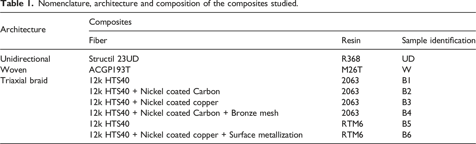
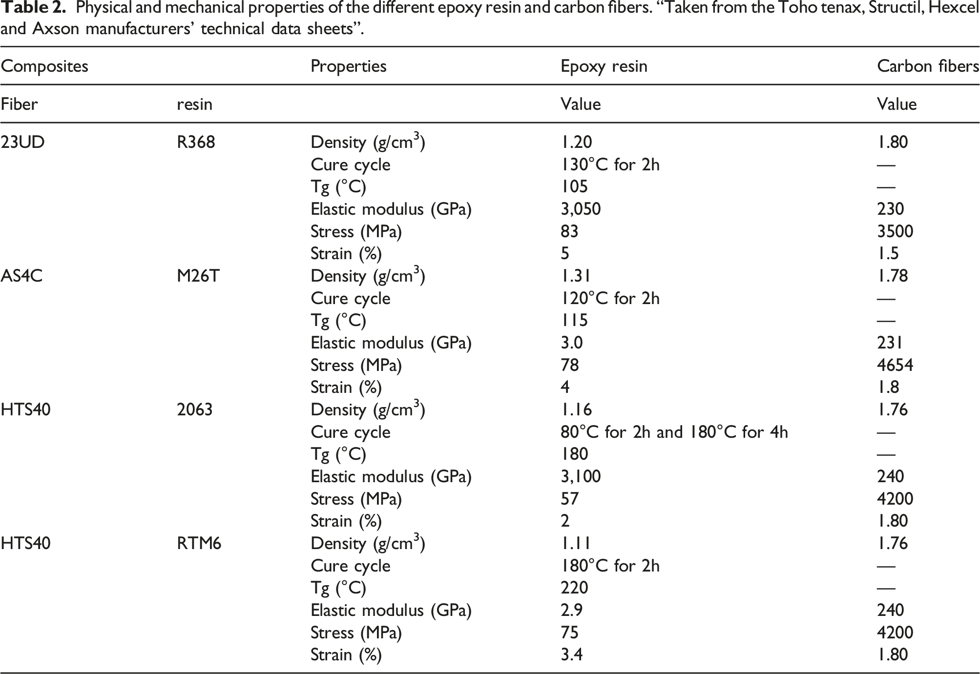
The laminate composites samples investigated in this survey was unidirectional, woven, and braided composites. The first material is composed of a R368 epoxy resin prepreg reinforced having 23UD unidirectional carbon fiber (commercial by Structil Company with the name of CTE1R368-1). The stacking sequence of this reinforcement is [0°/90°/45°/-45°/0°/-45°/45°/90°/0°]. The second material is composed of a M26T epoxy resin prepeg reinforced with AS4C woven carbon fiber Twill 2x2 (commercial by Hexcel Company with the name of M2650%ACGP193T2) having the sequence [0°/90°/45°/-45°/0°/-45°/45°/90°/0°]. The third type of materials are composed of a 2063 or RTM6 epoxy resin supplied by Axon Technologies and Hexcel, respectively, with various braided carbon fibers. These fibers were supplied by Toho Tenax which contain 12k HTS40 carbon, 12k HTS40 carbon + Nickel coated Carbon, 12k HTS40 carbon + Nickel coated copper, 12k HTS40 carbon + Nickel coated Carbon + Bronze mesh, and 12k HTS40 carbon + Nickel coated Copper + Nickel coated Carbon + Surface metallization. These braided composite materials were manufactured by Resin Transfer Molding Process. This process is the designation for a technology where, in general, a fiber preform is placed in a female mold, the male mold closes leaving a gap to allow the resin to be injected and to impregnate the fibers. The composites studied have an uniform thickness of about 2.4 mm and were provided by DJP composites (Figure 2). The nomenclature, architecture, and composition of the various composite materials used in this study was given in Table 1. The physical and mechanical properties of the different resin and carbon fibers are shown in Table 2. Schematic configuration of composites studied. Nomenclature, architecture and composition of the composites studied. Physical and mechanical properties of the different epoxy resin and carbon fibers. “Taken from the Toho tenax, Structil, Hexcel and Axson manufacturers’ technical data sheets”.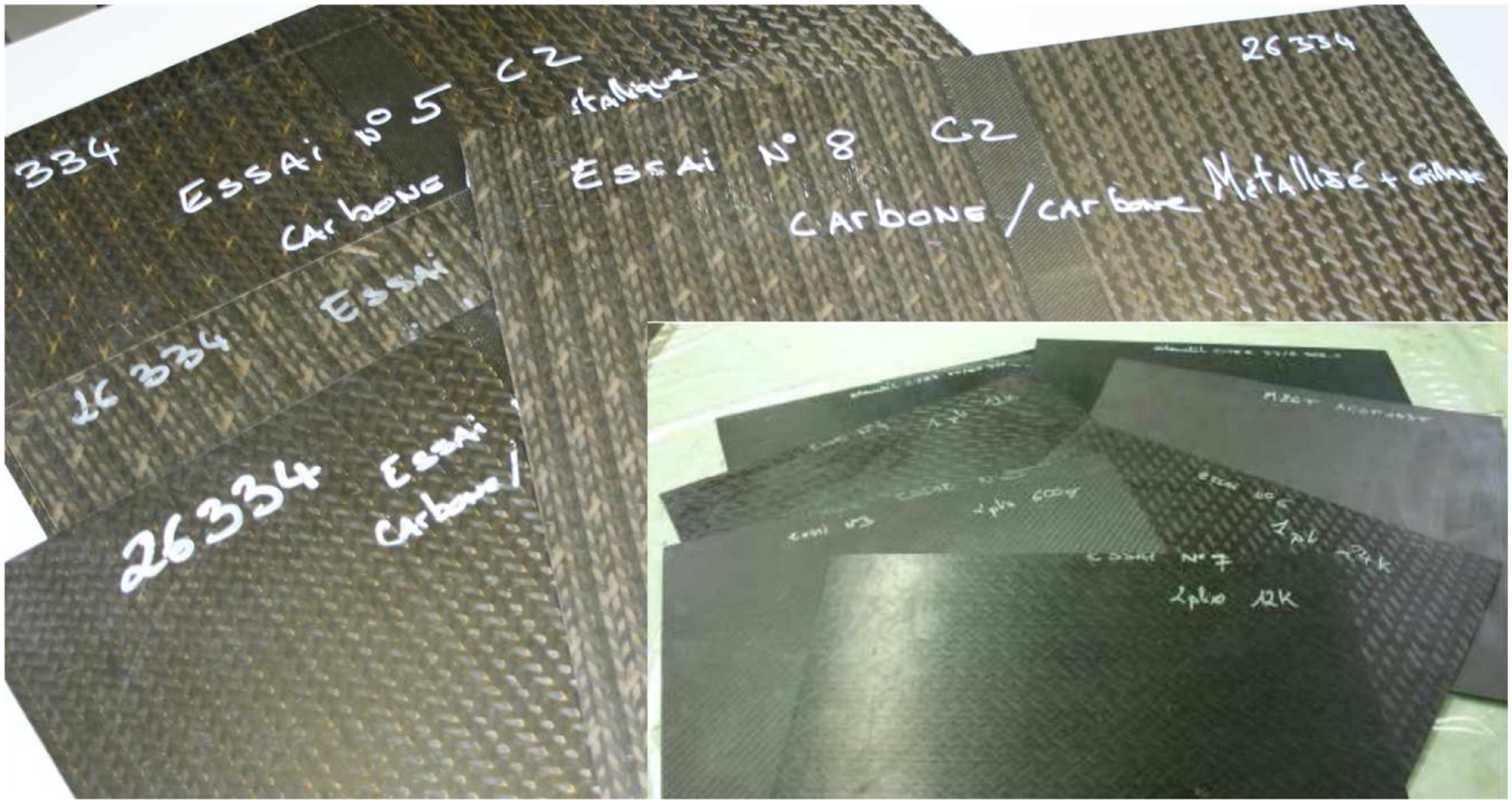
Thermal diffusivity and conductivity
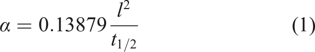
The thermal properties were measured by using a light flash analyzer (LFA 457 Micro Flash TM system by NETZSCH-Gerätebau GmbH, Selb/Germany). This device contains a xenon flash light that induce a pulse of energy on the bottom side of the sample. Thus, the pulse enables to increase the sample temperature and throughout an indium antimonide (InSb) infrared detector is measured the response time to the pulse of energy on the top side of the sample. The response time was computed to calculate the thermal diffusivity. The analytical formulation includes the Parker/adiabatic constant (ideal case) which leads to determine the thermal diffusivity as follows.
31

Density analysis
The density versus temperature relationship was described by the change in the volume due to the thermal expansion. For a cubic unit cell of a material, the mass at room temperature is
32

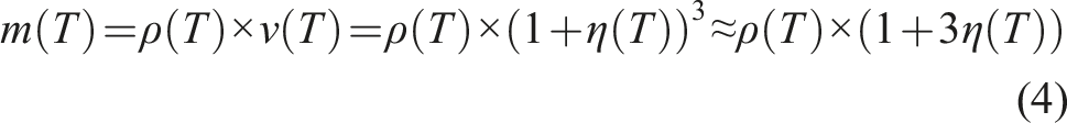
Or
Therefore
A pycnometer (MicroMeritics AccuPyc 1340 Pycnometer) was used to accurately determine the bulk volume as part of apparent density determination. The system was filled with helium. The volume of each section of the system was known. The pressure was measured, before and after, and a section at atmospheric pressure was added. The ideal gas law was used to determine the volume of a specimen. The mass was measured separately, and by combining the volume and mass information, we get the apparent density; apparent density = mass/volume.
Specific heat (Cp)
Specific heat capacity (cp) is a material property describing the energy required to induce a certain change in the temperature of a unit mass of the material. The DSC “Differential Scanning Calorimeter” measures specific heat capacity by heating a sample and measuring the temperature difference between the sample and a reference. Reference and sample crucibles are placed on a sample carrier within a furnace of cylindric geometry which generates heat radially toward the center. Temperature is detected by thermocouples in contact with each crucible. One thermoelement is shared between the crucibles allowing the temperature difference to be measured as a voltage. Three measurements are necessary for calculating specific heat. First a “Baseline” is recorded. This is the response with both crucibles empty, yielding a signal bias inherent in the system. Next is a reference test, in which a sample with a well defined specific heat is tested for comparison to an experimental sample. Finally, an experimental sample is tested. The “Baseline” allows removal of system bias from the data, while the reference test allows calculation of the specific heat of the experimental sample as a ratio of the reference material specific heat. The methodology of DSC is defined by the ASTM E967standard.
The calorimeter used in this research is the DSC—STA 449 F3 Jupiter® analyzer. Differential Scanning Calorimeter manufactured by NETZSCH. The temperature was programmed in the range of 25°C–1000°C at a heating rate of 20 °C/min, under air atmosphere.
Numerical approach
Finite Element Model—Representative Volume Element (RVE)
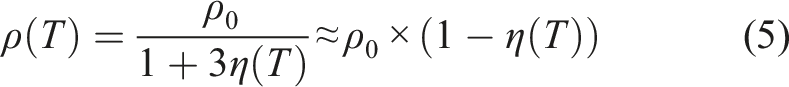
Nowadays, Finite Element Method (FEM) is one of the most important numerical analysis methods in the design or modeling of a physical phenomenon in various engineering disciplines. The FEM is thus a numerical procedure used to obtain solutions to a large class of engineering problems involving stress analysis, heat transfer, and fluid flow, which is very difficult to reproduce experimentally, and the cost is very high. Ansys is general-purpose finite element modeling package for numerically that allows solving a wide variety of thermal problems. In this study, Ansys software has been used in the finite element analysis to determine the thermal characteristics of various composite structures. In order to numerically simulate of the thermal conductivity of the different composites, a representative volume element (RVE) was constructed for braided fabric composite as given in Figure 3. The Representative Elemental Volume respects the global fiber rate and correspond to the spatial period of the fabric. The elementary constituents are: the resin pockets and the strands whose orientation is likely to vary with respect to the directions of the warp and the weft and the inclination for the out-of-plane wires. A braided fabric composite is a periodic structure and consequently it is not necessary to study the whole structure but only a RVE. This RVE is modeled with finite element code ANSYS. Representation of representative volume element of braided composites.
One of the general definitions for the RVE is associated to an image sub-region from which the properties averaged values are similar to those the bulk material. Regular uniform structures with a periodic arrangement of heterogeneities form the RVE which corresponds to an elementary periodic pattern. Jiang 33 defined the RVE as an infinite length scale limit, relative to the microscale in which the material appears uniform and the continuum concept may be applied. Drugan and Willis 34 adopted a more pragmatic definition. They defined the smallest volume associated to the usual spatially constant, for overall modulus macroscopic constitutive representation, which sufficiently accurate represent the mean constitutive response. The RVE size depends on the investigated property as mentioned by Kanit et al. 35
The first step of this modeling consists in building the geometry and the meshing of the braided fabric. To this end, lines generated by the intersecting of braiding yarns and the boundary planes should be meshed, and then the boundary planes are meshed based on the line mesh. Then, this volume is meshed with three-dimensional hexahedric elements called solid 45. In order to complete the meshing, the RVE is filled with resin. As the resin is assumed isotropic, solid 45 tetrahedric elements are used.
Theory of thermal conductivity
According to Fourier’s law, the rate of heat flow, 
Fourier’s law of heat conduction is an empirical relationship based on observation. Equation (7) holds for isotropic media in which
Thermal conductivity (
For non-isotropic media,
Results and discussion
Experimental Analysis
Specific heat capacity
Specific heat capacity is an important parameter for thermal conductivity calculation and was obtained by DSC analysis. It was measured for all the samples listed in the Table 1. The results acquired from these specimens were plotted in Figure 4. Overall, these results indicated that Cp curves were similar for all samples and it changed proportionally with the temperature. The specific heat was noted as increasing by increasing the temperature. It seems that the specific heat is influenced by the nature of the constituents. Further, it was observed that the replacement of part of HTS 40 carbon by nickel-plated copper wires enabled a decrease on the specific heat. These results corresponds to other obtained by Bradley et al.
36
and Messiha et al.,
37
when were investigated the AS4/3501–6 and IM7/8552-1carbon epoxy composite, respectively. Similar results were reported by Joven et al.
14
for the carbon fiber-epoxy prepregs with different fabric weaves. Heat capacity versus temperature of different composites.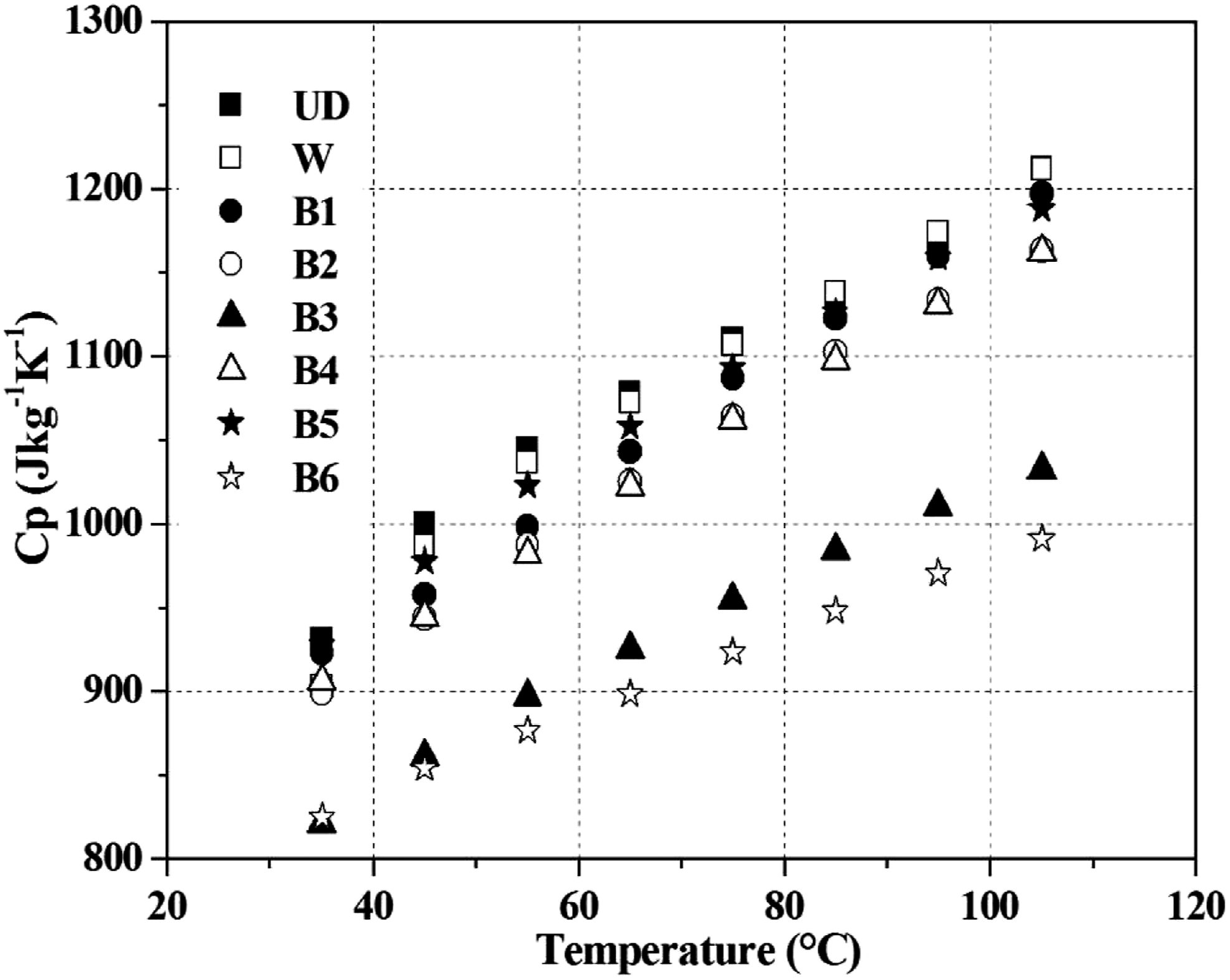
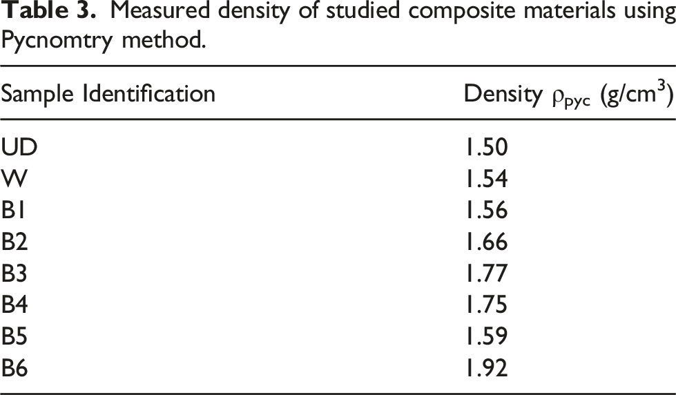
Density
Measured density of studied composite materials using Pycnomtry method.
Thermal diffusivity
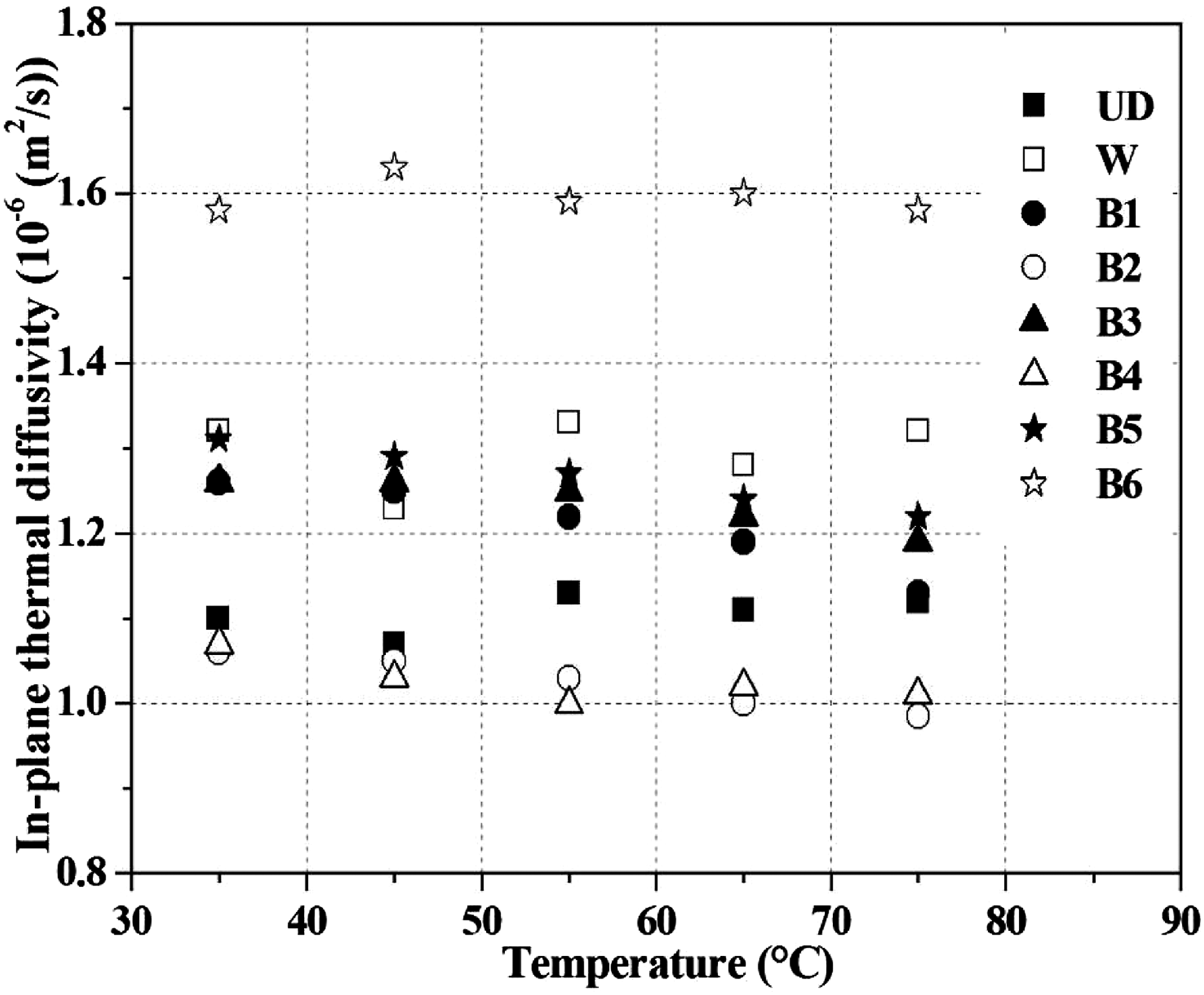
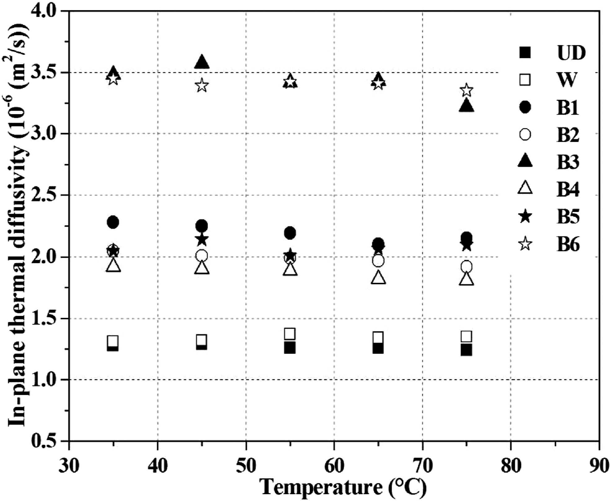
The relationships between the thermal diffusivity and the temperature for various types of composites were measured for a temperature range between 35 and 80°C. It was found that the thermal diffusivity of the composites decreases with the temperature. Details of results plot for transverse and in-plane thermal diffusivity versus temperature is shown in Figures 5–7, respectively. Transverse and in-plane thermal diffusivity are influenced mostly by their properties and the type of the matrix. The composite with a particular RTM6 resin shows the higher thermal diffusivity than one with 2063, R389 and M26T resin, respectively. The replacement of a part of the carbon fibers for the composite “HTS carbon braided/2063” with Nickel coated Carbon, Nickel coated Copper, or Nickel coated Carbon + Bronze, decreases the transverse and in-plane thermal diffusivity in the direction perpendicular of the carbon fibers. This is explained by the thermal contact resistance between the different fibers. Besides, in-plane, the thermal diffusivity was observed larger in the fiber direction of the composites with nickel coated copper (B3), noted in Figure 7. Similarly, the replacement of a part of the carbon fiber for the composite fibers “HTS carbon braided/RTM6” with “Nickel coated copper + Surface metallization” revealed an increase in the transverse and in-plane thermal diffusivity along its perpendicular direction of the carbon fibers. Transverse thermal diffusivity versus temperature. In-plane thermal diffusivity and perpendicular to the fiber direction. In-plane thermal diffusivity and along to the fiber direction.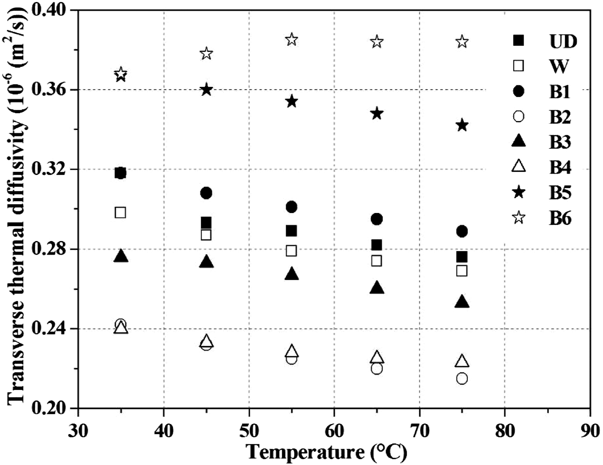
Thermal Conductivity
The measured thermal conductivity for the studied composites is shown in Figures 8–10. Transverse thermal conductivity versus temperature. In-plane thermal conductivity perpendicular the fiber axis direction. In-plane thermal conductivity along the fiber axis direction.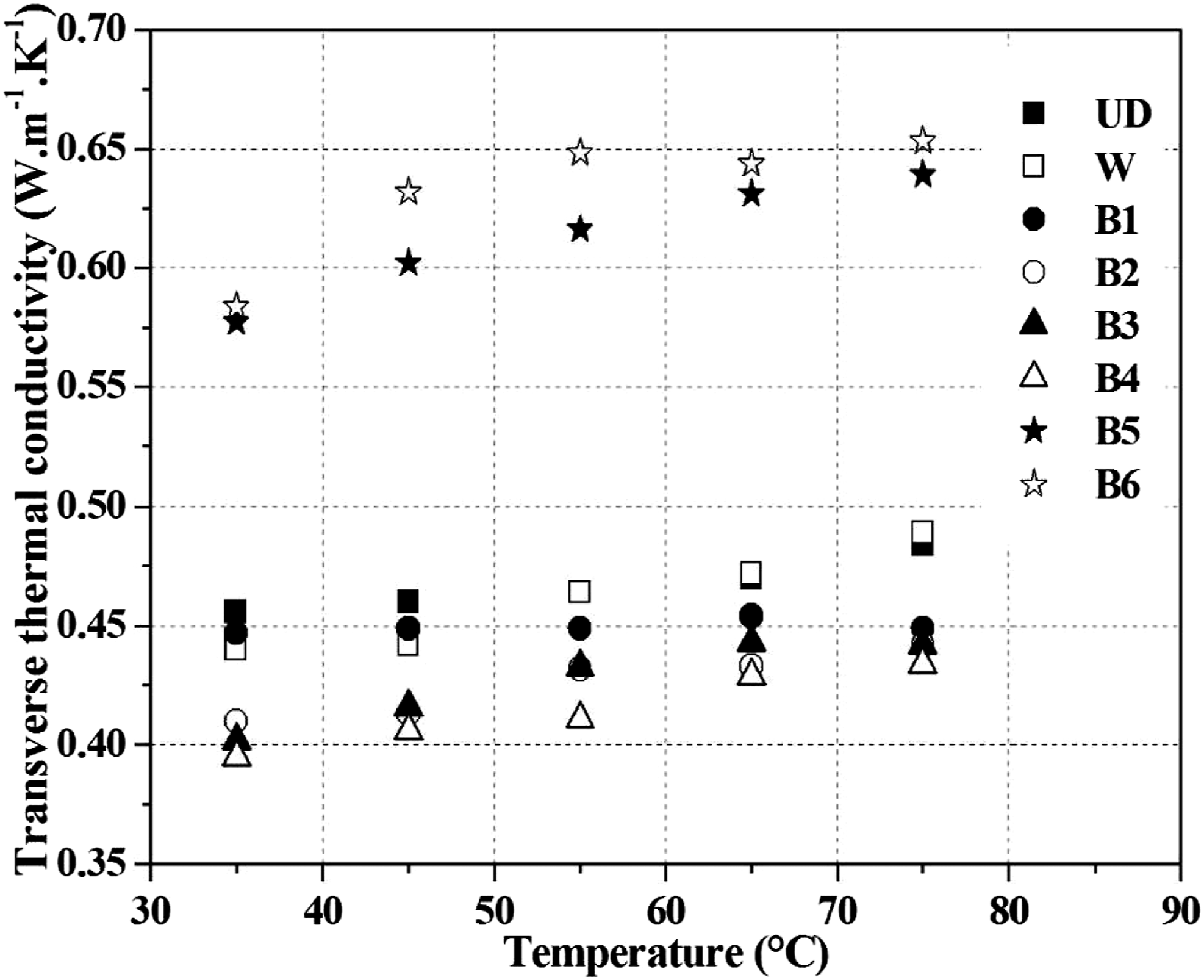
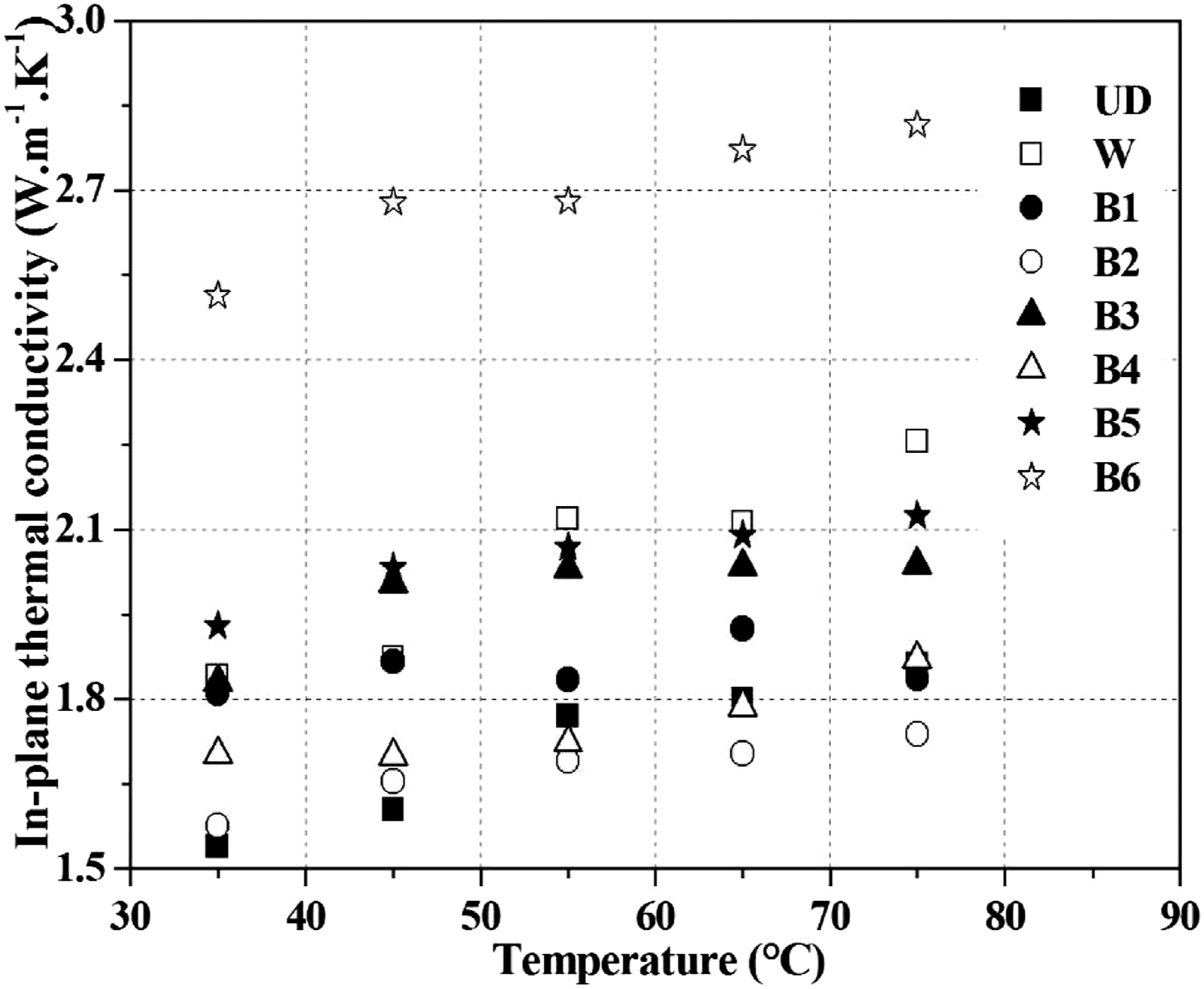
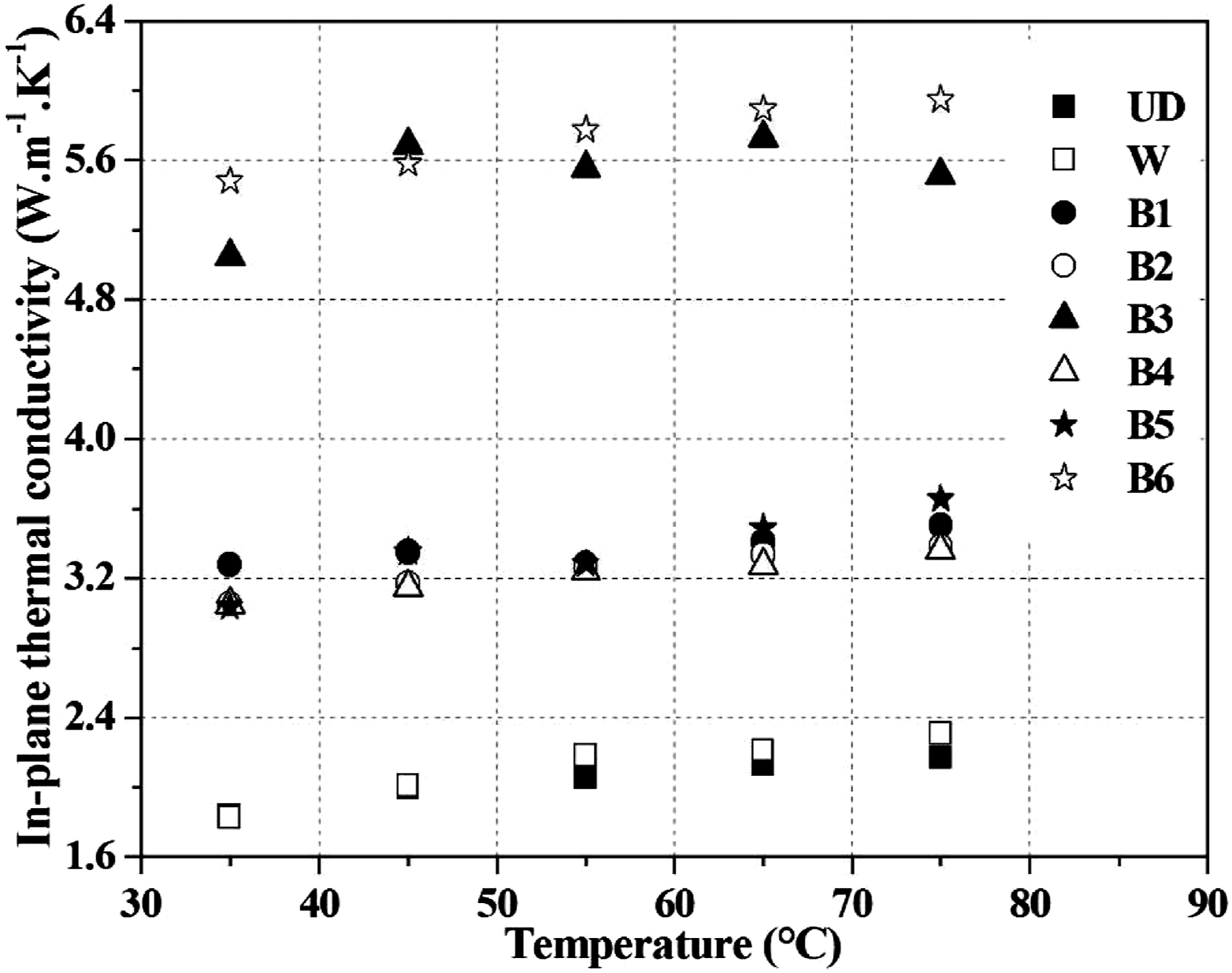
In this research, the thermal conductivity of these composites was linked to the thermal diffusivity. The thermal conductivity is influenced by the properties and the type of the matrix and fibers. We have noted that the thermal conductivity of the composites investigated did not changed with the increase in the temperature. Yet, we have noted that the transverse thermal conductivity is much lower than the in-plane, in the parallel and perpendicular directions of the fibers. Indeed, the difference of the transverse thermal conductivity and in-plane one in the parallel and perpendicular directions of the fibers of the sample (B3) containing nickel coated copper is more than 92% and 78%, respectively. The replacement of a part of the composite fibers “HTS carbon braided/RTM6” with “Nickel coated copper + Surface metallization” did not change the transverse thermal conductivity but increase the in-plane thermal conductivity for in the parallel and in the perpendicular direction of the fibers. Further, the bronze mesh in sample (B4) does not have an influence on the thermal diffusivity of the composites. These values of the transverse thermal conductivity were compared with the literature 35 for the woven carbon fiber-reinforced epoxy matrix composites, that is approximately 0.5 W/m.K when is used about 49% fiber volume content. Then, in-plane, thermal conductivity was obtained from the composite woven (W) for the two directions parallel and perpendicular, being approximately 2 W/m.K. This value corresponds to results obtained by Mayer et al., 38 when was investigated the carbon-epoxy woven prepreg laminates. The sample “HTS carbon + Nickel coated copper + metallization area/RTM6” shows higher transverse and in-plane thermal conductivity as well as in parallel and perpendicular direction of the fibers, that is approximately 0.7; 3 and 6 W/m.K, respectively. Transverse thermal conductivity of this carbon composite is close to that of neat resin, indicating that thermal property of the resin plays a major role in this direction.
The results of thermal conductivity obtaind in this work are in accordance with the results published in the literature. Mutnuri 39 has studied the thermal conductivity characterization of composite materials. He has found that the thermal conductivity along longitudinal direction in case of carbon/Vinyl ester composite is almost twice the conductivity in transverse and four times greater than through-the-thickness direction. Koráb et al. 40 investigated the thermal conductivity of the continuous carbon fiber-reinforced—copper matrix composite. They have found that the transverse thermal conductivity is not satisfying and does not depend on fiber orientation. It should be improved in the future in order to assure the composite’s competitiveness. Because carbon fibers are not very good conductors in transverse direction one of the possible route is to increase the overall copper content in the composite and producing the interconnected copper network.
These experimental results were used as data base to validate the numerical model in order to find a composite structure with better transverse thermal conductivity.
Numerical Analysis
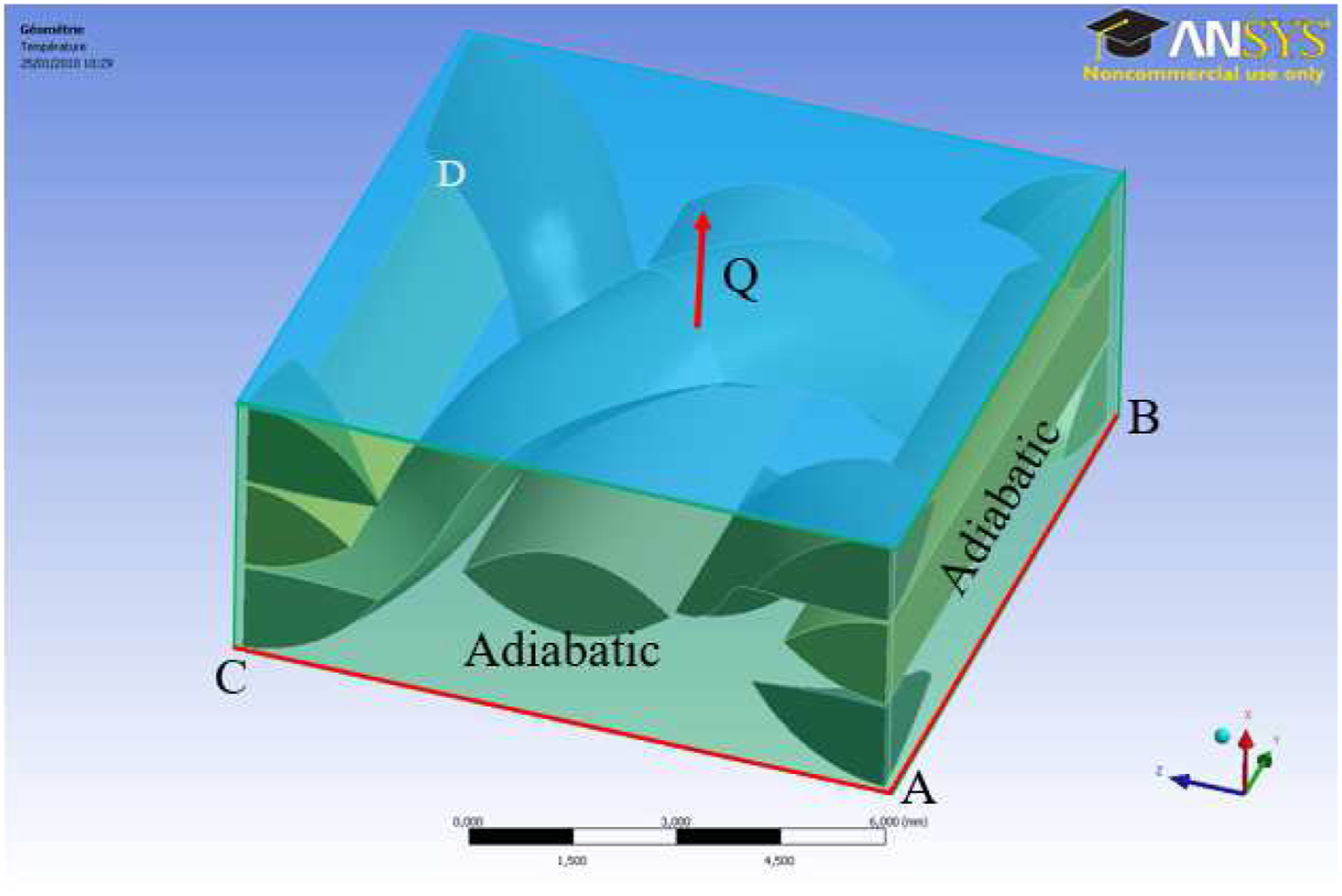
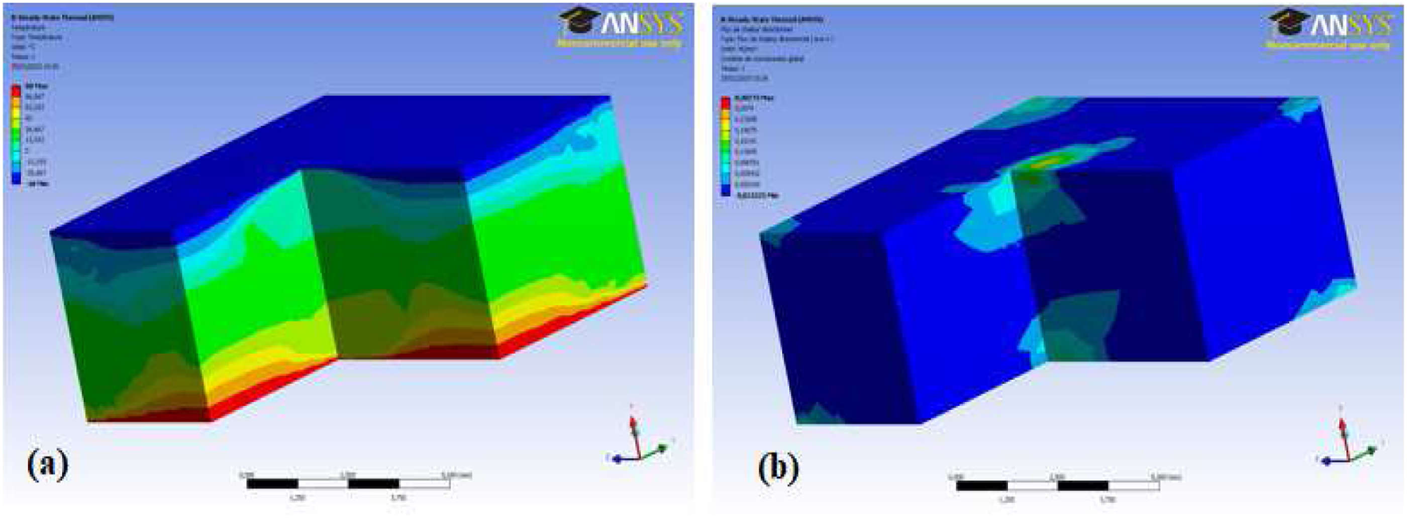
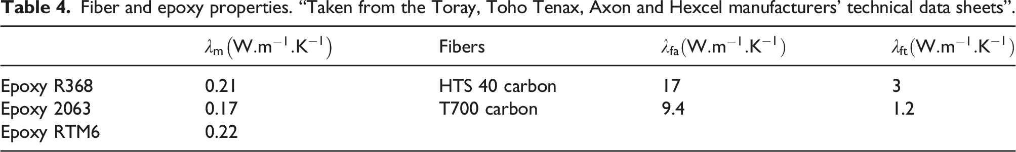
In the present numerical analysis, the heat conduction that is considered as the temperatures which occur at the nodes along the surfaces ABCD is prescribed as T1. The heat flow direction and the boundary conditions are shown in Figure 11. The other surfaces parallel to the direction of the heat flow are all assumed adiabatic. The temperatures at the nodes in the interior region and on the adiabatic boundaries are unknown. The temperature boundary conditions yield an upper bound which allows to estimate the thermal conductivity and flux boundary conditions on the lower bound. The difference between the bounds is used as an indicator of the adequacy of the mesh density. These temperatures are obtained with the help of finite element program package ANSYS. In order to avoid a too costly mesh refinement, we have refined the mesh at the interfaces. The dimension of this mesh was validated by comparing the results obtained with this mesh and a fine mesh. The temperature field and heat flow along the thickness direction of composites are presented in Figure 12. The thermal conductivity of constituents is presented in Table 4. These properties have provided by the manufacturer.
Where λ
fa
is the thermal conductivity of the fibers in the axial direction, λ
m
is the thermal conductivity of the matrix, and λ
ft
is the thermal conductivity of the fibers in the transverse direction λ
ft
. The thermal resistances of contact between the various constituents are as follows: Boundary conditions. (a) Temperature field for composites and (b) heat flow along the thickness direction of composites. Fiber and epoxy properties. “Taken from the Toray, Toho Tenax, Axon and Hexcel manufacturers’ technical data sheets”.

The transverse and in-plane thermal conductivities ( - The longitudinal fibers are considered to be perfectly right. But when they are folded, these have allowed the diffusivity of the composite to be reduced during the measurement. - The measurement device used in this study does not allow to measure the thermal conductivity on a RVE which takes into account the all braiding. Comparison between numerical and experimental results of various composite materials.
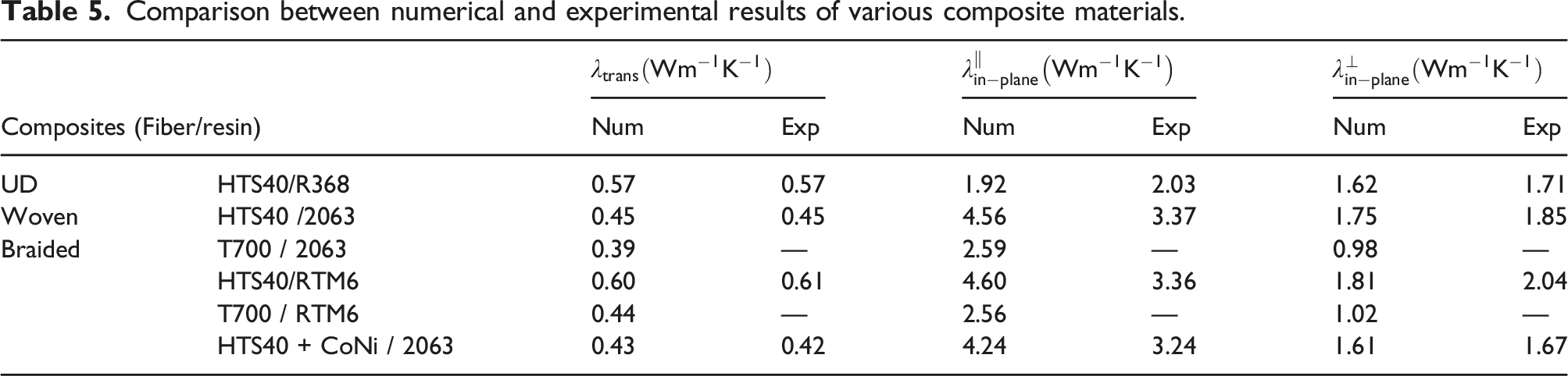
The finite element method is a robust tool employed to determine effective thermal conductivity of these composite which have different parameters as fiber architecture, fiber type, and nature type. The value of equivalent thermal conductivity obtained for various composite using numerical model are in reasonable agreement with the experimental values. The transverse thermal conductivity of these composites remains low at this stage of work. The validation of this numerical model makes possible to predict thermal conductivity of other composite materials having other architectures and constituents. In what follows, we will investigate the effect of fiber architecture, fiber nature, and resin nature in order to find the best transverse thermal conductivity.
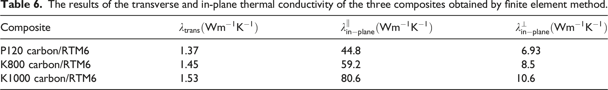
Influence of fiber type on thermal conductivity
The results of the transverse and in-plane thermal conductivity of the three composites obtained by finite element method.
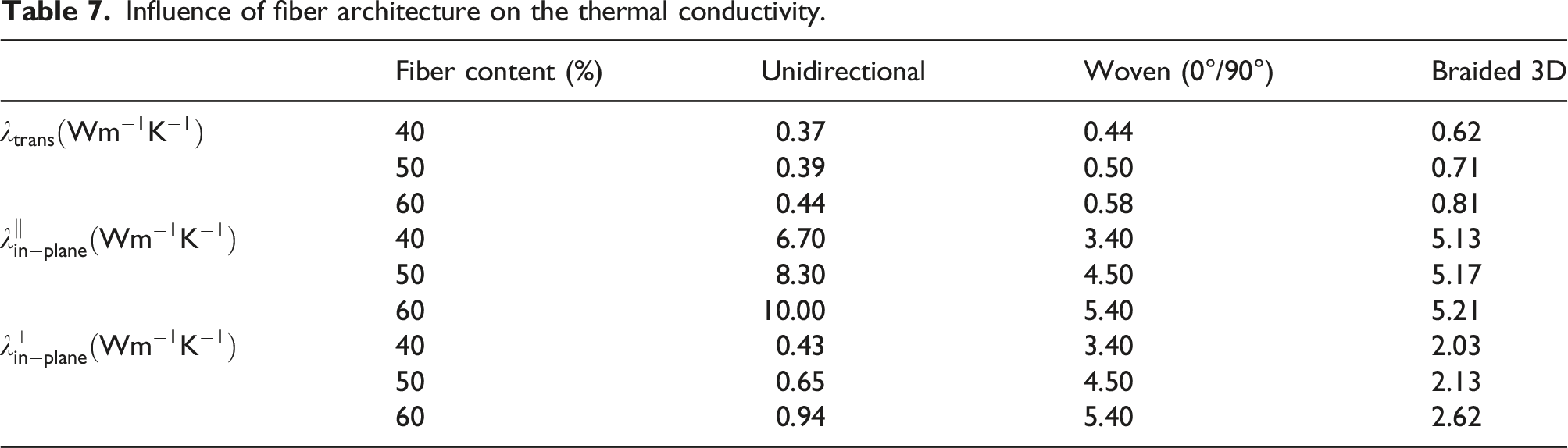
Fiber architecture effect on the thermal conductivity
Influence of fiber architecture on the thermal conductivity.
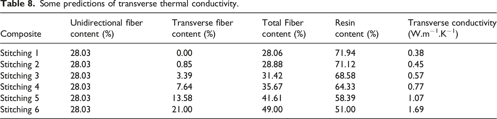
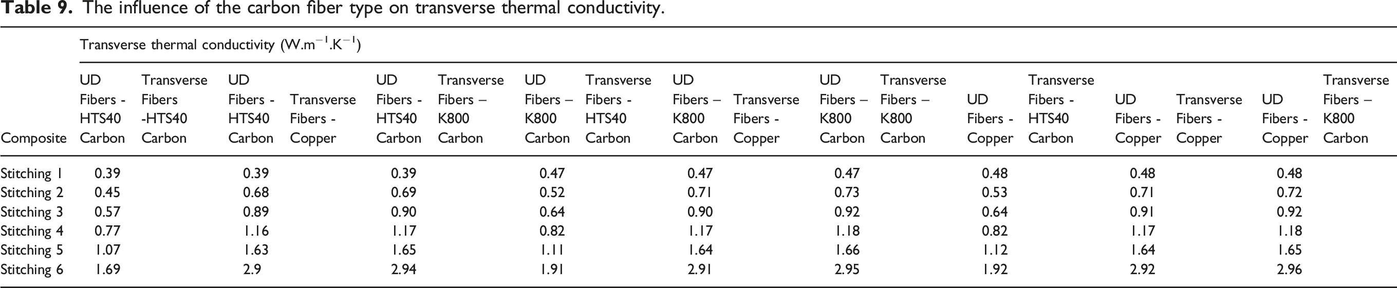
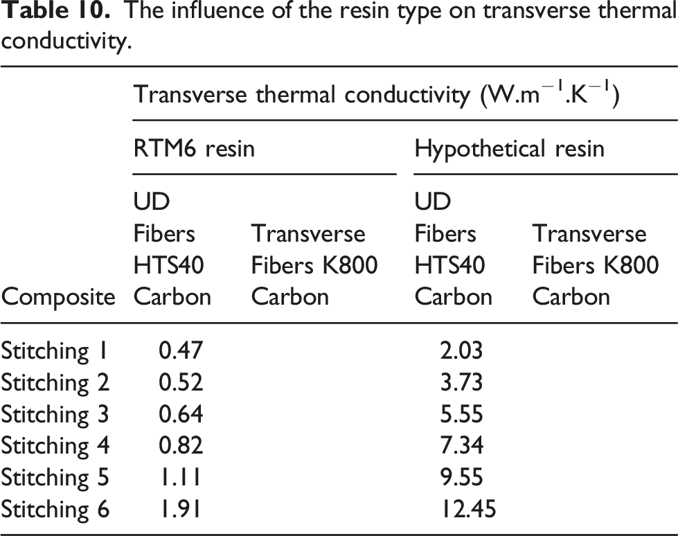
In this numerical study, we have identified the effect of parameters linked to the geometry and nature of materials for thermal conductivity of composite materials. This work can be used as a database for the identification of materials properties. Also, it permits an appropriate choice of the manufacturing process for the development of composites to meet a given specification associate to the thermal properties. At the end of this study, we proposed a composite with fibrous architecture optimized for transverse thermal conductivity (see Figure 13). This optimization was obtained by simultaneously varying the cross-section of the wires, the angle of inclination of the copper fibers and the orientation of the fibers in the plane. The inclination of the copper fibers ranges from 30 to 90°. The orientation of the fibers between two plies ranges from −45 to +45°. This architecture consists of unidirectional fibers oriented at 0° and 90°, and a transverse stitching between the unidirectional fibers. Table 8 presents details of numerical results of transverse thermal conductivity of this proposed composite. The selected constituents for composite material are HTS40 carbon fibers and an epoxy matrix RTM6. Further, the predictions of transverse thermal conductivity as a function of fiber volume fraction for the samples was shown in Table 8. By increasing fiber volume fraction fibers, the effective thermal conductivity of the polymer composite is improved. At the highest transverse volume fraction of 21% continuous fiber (stitching 6), the effective thermal conductivity was 1.69 W/mK which represents 77% of improvement over the composite with stitching 1. Table 9 shows the influence of the carbon fiber types on transverse thermal conductivity. The transverse stitching 1–6 used have the same fiber volume content as previously mentioned. The matrix used is epoxy RTM6. Taking into account mass imperatives, it is found that the best fibrous architecture appears to be a unidirectional HTS40 carbon fiber arrangement with K800 carbon fibers in transverse stitching. Following a comparative study, we have found that the best fibrous architecture appears to be a unidirectional HTS40 carbon fiber arrangement with K800 carbon fibers in transverse stitching. Moreover, since the resin is an important element to improve the transverse thermal conductivity of the composite. Also, other series of simulations was made using a hypothetical resin having a thermal conductivity of 2 W/m.K. The results of these simulations are presented in Table 10. It is noted that the transverse thermal conductivity of the composite with hypothetical resin is higher when compared as the composite with RTM6 resin. An optimized representative volume element of composite. Some predictions of transverse thermal conductivity. The influence of the carbon fiber type on transverse thermal conductivity. The influence of the resin type on transverse thermal conductivity.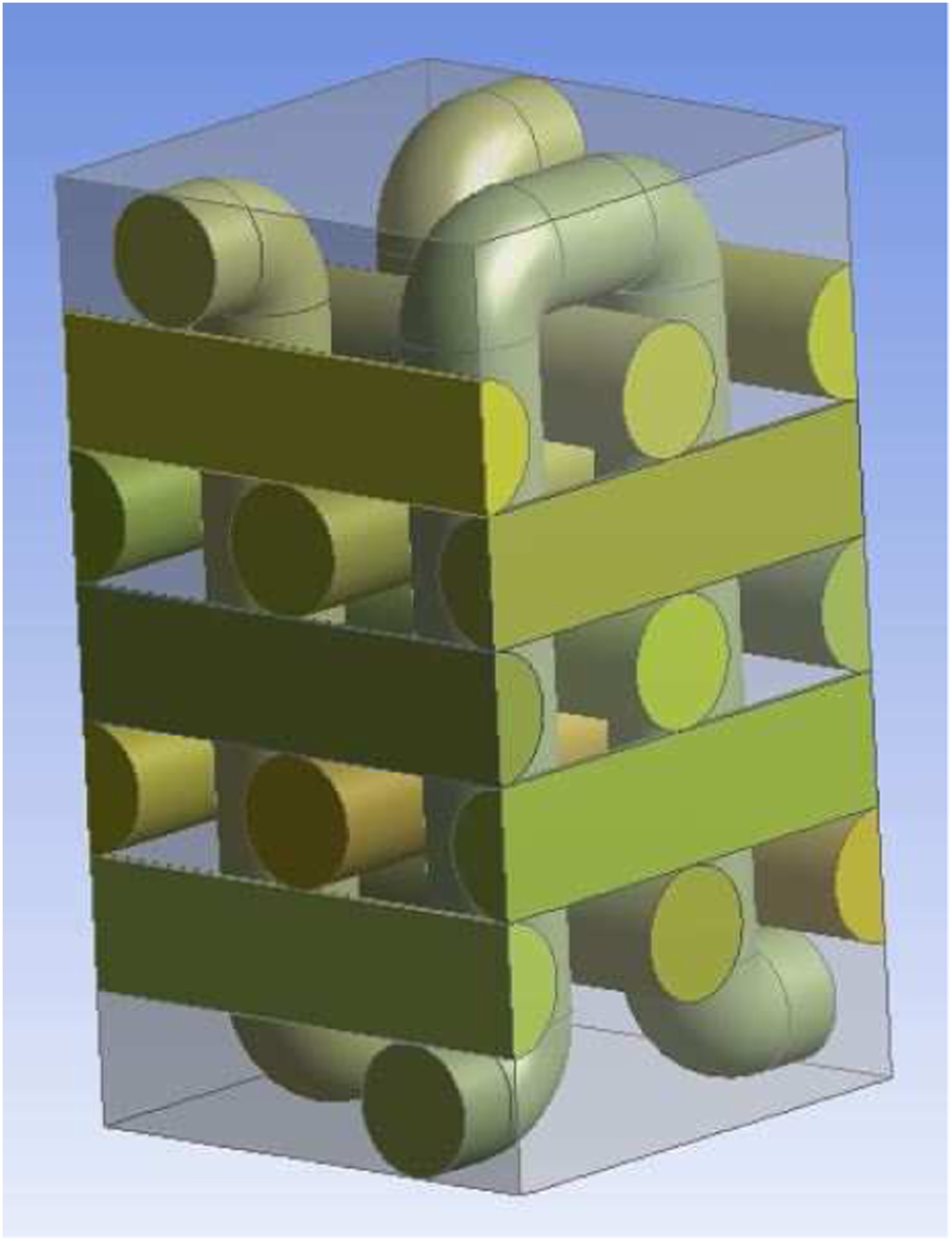
Conclusion
The aim of this study was to propose a composite material having a good transverse thermal conductivity able to dissipate the heat. First, the experiments were carried out to determine the transverse and in-plane thermal conductivity of various composites materials. The main results can be summarized as follows: • In-plane thermal conductivity of the composite “12k HTS40 + Nickel coated copper + Surface metallization/RTM6” shows better performance when compared to the different composites studied. • The thermal conductivity of composite “12k HTS40 + Nickel coated copper + Surface metallization/RTM6” are highest along the fiber direction, medium in the perpendicular direction and lowest in through-the-thickness direction, that is, approximately 6; 3 and 0.7 W/m.K, respectively.
Apart, this experimental investigation was focused to determine a database experimental which allows to validate the numerical model in order to optimize the structure of the composite material. The results obtained from the experimental method enabled to validate the results obtained by FEM simulation using ANSYS. Then, it was seen that the FEM can be gainfully employed for determination of effective thermal conductivity of fiber-reinforced polymer composites with different volume concentration of fiber, fiber type, resin type, and architecture. In the numerical study, we have found that the best fibrous architecture appears to be a unidirectional HTS40 carbon fiber arrangement with K800 carbon fibers in transverse stitching. It was noted also that the transverse thermal conductivity of the composite with hypothetical resin is higher when compared as the composite with RTM6 resin.
Footnotes
Acknowledgements
This work is a part of the THERMELEC project. It is supported by the DGE through the ASTECH competitiveness cluster, in which several partners are collaborating (Région Basse-Normandie, Company hispano-Suiza, Dassault Aviation, DJP, MADEP, LI2C, INRETS, SERAM, LEG, CNRT Matériaux Caen).
Declaration of conflicting interests
The author(s) declared no potential conflicts of interest with respect to the research, authorship, and/or publication of this article.
Funding
The author(s) received no financial support for the research, authorship, and/or publication of this article.