
Abstract
The aircraft structures are threatened by soft material impact such as birds and hail ices. The main objective of this study is to develop a comprehensive experimental method to evaluate the resistance performance of carbon fiber reinforced polymer laminate subjected to ice impact loadings. First, a hollow tube sensor was adopted to measure the impact force of ice projectiles. Based on the deformation process captured by a high-speed camera and the analysis on transmitted energies obtained by the tube sensor, the repeatability of the ice impact loadings was confirmed and its impact behavior was analyzed. Second, six T700/epoxy carbon reinforced polymer laminates were impacted with different loading velocities, where the transient deformation data during impact were obtained by 3D digital image correlation method The post-test detection was realized using both optical microscopes and scanning acoustic microscopes. The impact of ice projectiles resulted in distributed loadings on the laminate targets with invisible inner matrix cracks and delaminations. Irregular distributions of delaminated areas subjected were observed and their sized increased with the impact velocity. The experimental method showed its practicability on impact issues with projectiles of unknown properties.
Keywords
Introduction
One of the greatest concerns lying on aircraft design and engineering is the soft body impact event, which can be defined as impact events where the strength of projectiles is much less than the shock pressures. 1 The airplanes, during taking off and landing, are commonly threatened by flying objects, especially birds and hail ices. With relatively high speed, these soft projectiles can cause tremendous damage to the plane structures such as windshields, leading edges and fan blades. In recent decades, the fiber reinforced plastic (FRP) has played an important role in replacing metal materials applied on aircraft structures due to its high strength, high stiffness, and low density. It has therefore been increasingly important to study the mechanical properties of FRPs so as to effectively estimate and design related structures. Different from metal structures, the damage modes of FRPs are often invisible including matrix cracking and delamination. Moreover, there is usually no residual deformations on the impacted region when subjected to low-speed tool drops or bird strikes. Therefore, researches on the failure mechanism, measurement, and prediction methodologies of FRPs have attracted considerable amount of attentions in the 21st century.
Delamination is the most common failure mode and can significantly reduce the overall mechanical properties of laminate materials. 2 Most of the fracture mode of delamination appears to be tensile opening (mode I) because of the lowest energy required for its initiation. 3 Based on numerous experiments with multidirectional laminated composite, the energetic-based criteria are more accurate than stress-based ones. 4 By ignoring the delamination size and location, Suemasu and Majima5,6 developed an analytical model to calculate the energy release rate and consequently the onset of multiple delaminations, which was used afterward by R. Olsson et al. in his extensive investigations.7-10 Olsson et al. used spring-mass models to describe the dynamic process of impact event including the delamination initiation and growth. In their researches, the delaminations were assumed to be peanut shaped and simplified as elliptical. Their models were further extended by Salvetti et al. 11 with stiffness degradation considered. Similar models were used by Wu et al. 12 to study the perforation process of FRP laminates subjected to flat-end projectiles and the delamination area were assumed to be circle. Harpreet Singh 13 divided the targets into two regions: the damaged areas and the undamaged areas and calculated the combined stiffness of a laminate panel with a low-rigidity central disk joined to a stiffer annular plate. All these models had persuasive comparisons with either experimental or numerical results. However, the spring-mass system uses rough assumptions including the effective stiffness, simplified loading and responding processes, and above-mentioned standardized delamination shapes. This therefore results in limitations when using them in specific research conditions.
The direct cause of delamination should be the interlaminar normal and shear stresses,14,15 which could either be brought by related external loadings or deformation induced tensile-shear couplings. Unfortunately, these data can hardly be obtained experimentally based on existing techniques. In order to numerically study the delamination behavior of laminated materials, the cohesive zone modeling (CZM) method has been widely employed, 16 which inserts zero-width cohesive element layer between the multidirectional composite layers. With appropriate energy-based failure conditions, the delamination process can effectively be predicted.17-20 However, the existence of cohesive element can dramatically increase the cost of computational resources due to the complex contact calculations, bringing inconvenience in the large-scale evaluation simulations. To illustrate this issue, Sebastian Heimbs, and Tim Bergmann 21 compared different insertion configurations of the cohesive interfaces while analyzing the impact responses of prestressed composite plates. They found that increasing the number of inserted cohesive interfaces can increase the quality of results while considerably increasing the simulation time and the frequent model instabilities. This proves that the numerical investigations on the delamination problems highly relies on the performance of computational resources.
The determination of the parameters of the simulation model and the evaluation of the analytical model should be conducted by comparing them with experimental results. Under the loading condition of high-velocity impact, the collection of these data is relatively more difficult compared with quasi-static experiments due to the considerable interference and coupling among the loading, deformation and the data acquisition methods. The force data measured by either the pressure sensor 22 or the strain gages 23 are limited according to certain specimen materials considering the wave-dominated response behavior. M.A. Lavoie 24 used a rigid target and carbon gages to evaluate the shock pressure subjected to gelatin projectiles, which can reduce the wave-dominated effect. He also employed a high-speed camera to quantify the deformation process of the projectile. This non-contact method can be further developed into the digital image correlation (DIC) method, which uses one or two cameras to obtain the displacement information of the target regions.25-27 In the field of impact experiments, the DIC results are basically used to measure the real-time deformation and further evaluate the constitutive parameters.28-30 A deeper utilization of DIC full-field data is one of the inspiring factors to the present study.
Ice has different inelastic behaviors when increasing the deformation rates. In the impact phenomenon, ice shows brittle behavior while it is ductile when subjected to lower-rate loadings (<10−4). 31 The experiments presented by Kelly et al. 32 shows that the impact of ice projectiles has qualitative similarities to other brittle materials. However, the classical ceramic models did not produce ideal results in the numerical study. The use of a pressure-dependent model, Drucker–Prager model can also be found in 33 and, 34 showing that the ice material has considerable pressure sensitivities. Also, a bilinear elastic–plastic model was employed by Kim et al.35,36 Wilbeck 1 treated the ice as a soft material considering the large difference of strength between the targets and the projectiles and therefore used hydrodynamic models to describe its impact behavior. Although these models can satisfy the specific research conditions, it can be concluded that further experiments and more comprehensive understandings of ice materials are required.
The impact loading created by soft projectiles is highly distributed and time-dependent. Based on the wave impedance matching, this kind of shock pressure generated in the target can hardly cause perforations or penetrations. When the impact velocity is not large, only matrix cracking and delamination will occur, which is usually invisible. After the deformation results are recorded by the DIC technique, the acoustic microscope or the section observation is required to observe the damage information of the specimen. This paper suggested a comprehensive experimental method to investigate the dynamic responses of carbon fiber reinforced plastic laminates subjected to ice impact. The impact behavior of the ice projectile was investigated using a hollow tube sensor and a high-speed camera. In order to evaluate the repeatability of this loading condition, the impact force and transmitted energy of ice projectiles were both analyzed. The 3D-DIC technique was adopted to record the dynamic response of the CFRP coupons and the influences of impact energies were discussed, while their damage mode were analyzed using post-test detections of both optical microscopes and scanning acoustic microscopes.
Experimental method
The impact force measured by a tube sensor
Before conducting the impact tests on CFRP laminates, the impact behavior of ice projectiles used in this study were investigated using a tube sensor. The different impact behavior between ice projectiles and typical hard projectile is that it may easily get crushed or cracked during launching process, which results in mass loss and properties change. This phenomenon could increase the divergency of its impact force and should be evaluated before used in the impact tests. Also, the attitudes of the projectiles before the impact take place should be well controlled to ensure the repeatability of the experiments. On the other hand, the freezing process in the fabrication process of ice projectiles may generate inner cracks and prestresses which should have influences on their impact behaviors. Therefore, the impact force data obtained from these tests are required to effectively validate the finite element model and constitutive parameters of the ice projectiles in future works.
Also, the repeatability of ice projectiles was required to be confirmed. Although several methods can be found to make different shapes of ice projectiles,36-39 the crystallization process during molding can unavoidably create internal stresses or even cracks and affect their mechanical performance. Therefore, the necessity of evaluating the impact behavior of the ice specimens cannot be ignored. A measuring method developed by Jeremy et al., 40 which was originally used to measure the shock force of gelatin projectiles through a tube sensor, is also considered appropriate in investigating the dynamic properties of ice projectiles.
The fabrication of ice specimen in this section is the same as the following impact experiments, where a metal mold was filled with distilled water and then placed into the freezer, see Figure 1(a). In order to compare the impact behavior of different types of ice specimen: monocrystalline and polycrystalline, Combescure
39
developed two fabrication processes. It was found that the results were not significantly affected by the microstructure of ice specimens. Therefore, the simpler process was adopted to make polycrystalline ice projectiles, where a mixture of water and crushed ice were filled and being frozen. The flat-end cylindrical specimen was 80 mm in length and 40 mm in diameter. A relatively warm temperature (about −5°C) and long freezing process (about 48 h) was set in order to reduce the influence of internal stresses. Then the specimens were demolded by warming the mold and were separately stored in plastic bags in the temperature of −25°C. The temperature effect was not discussed in this study, and the stored ice projectiles were immediately launched (in 1 minute) together with their sabots once took out from the plastic bags. Hollow tube experimental facilities: (a) metal mold for ice projectiles, (b) test bed, (c) schematic gas gun test system, (d) foam-made sabot (e) steel sabot stripper.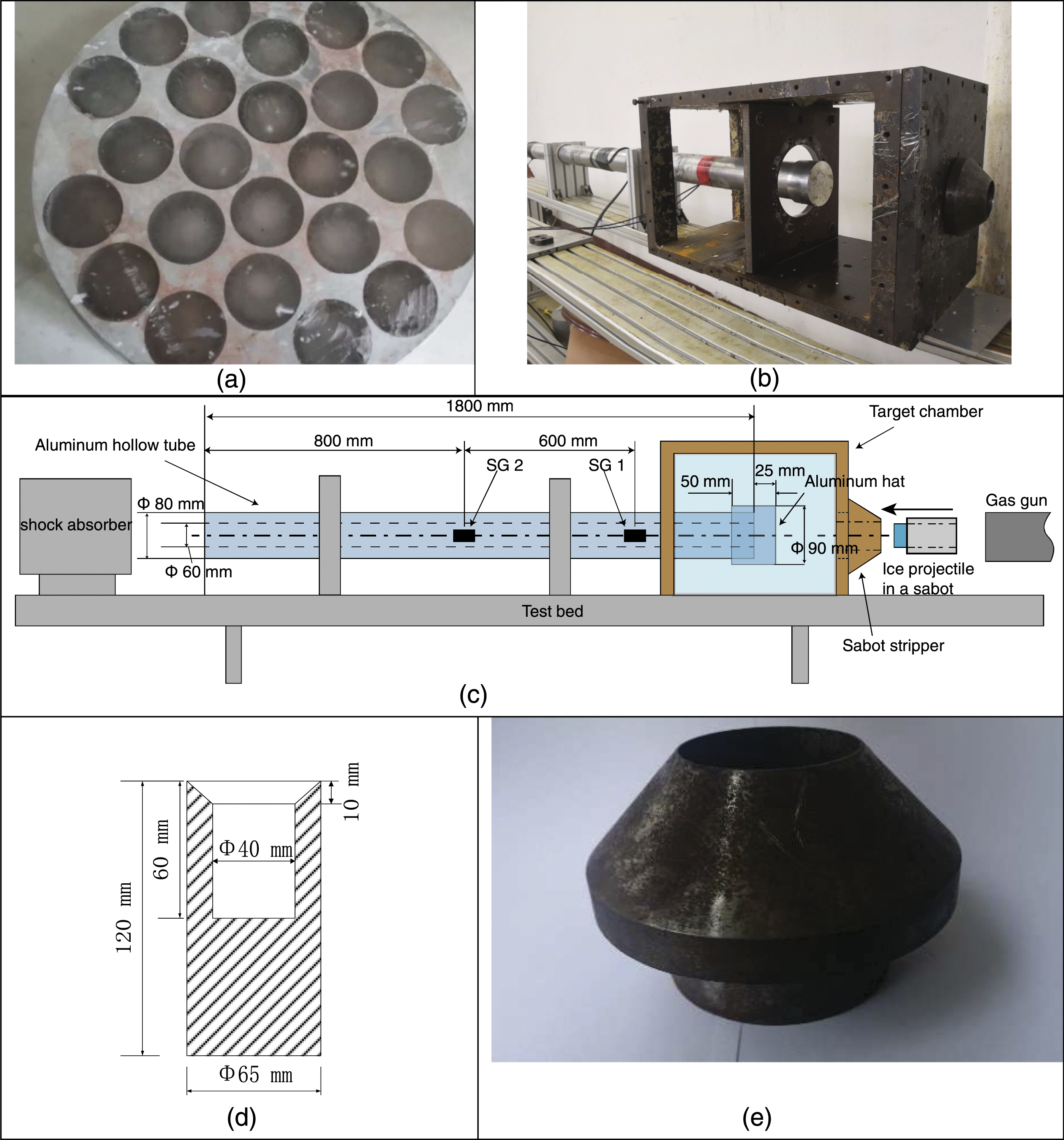
Figure 1(b) and Figure 1(c) shows the assembled tube sensor motivated by Jeremy et al. 40 This testing system was modified from a Split Hopkinson Pressure Bar system. The ice projectiles were launched by a gas gun, which uses pressurized gas as the driving force. The foam-made sabots (Figure 1(d)) were used to carry the projectiles for effective protection and thermal insulation. Before the impact occurs, the sabots were blocked by an iron stripper (Figure 1(e)) and the projectiles can be released through its central tunnel (50 mm in diameter). The interference to the trajectory generated during the sabot separation was ignored taking into consideration its short-lasting procedure and negligible frictional force between the ice and the foam. This test used the hollow tube, with an inner diameter of 60 mm and an outside diameter of 80 mm, instead of a solid bar to reduce the inertial effect and raise the signal-to-noise ratio. The resistance strain gages (BX350-3AA) with a sensitivity coefficient of 2.08 were employed to measure the shock wave in combination with a Wheatstone bridge circuit. In order to evaluate the attenuation of the shock force while propagating along the tube, two pairs of strain gages (SG one and SG2) with different positions were employed.
T700/epoxy laminates impact tests
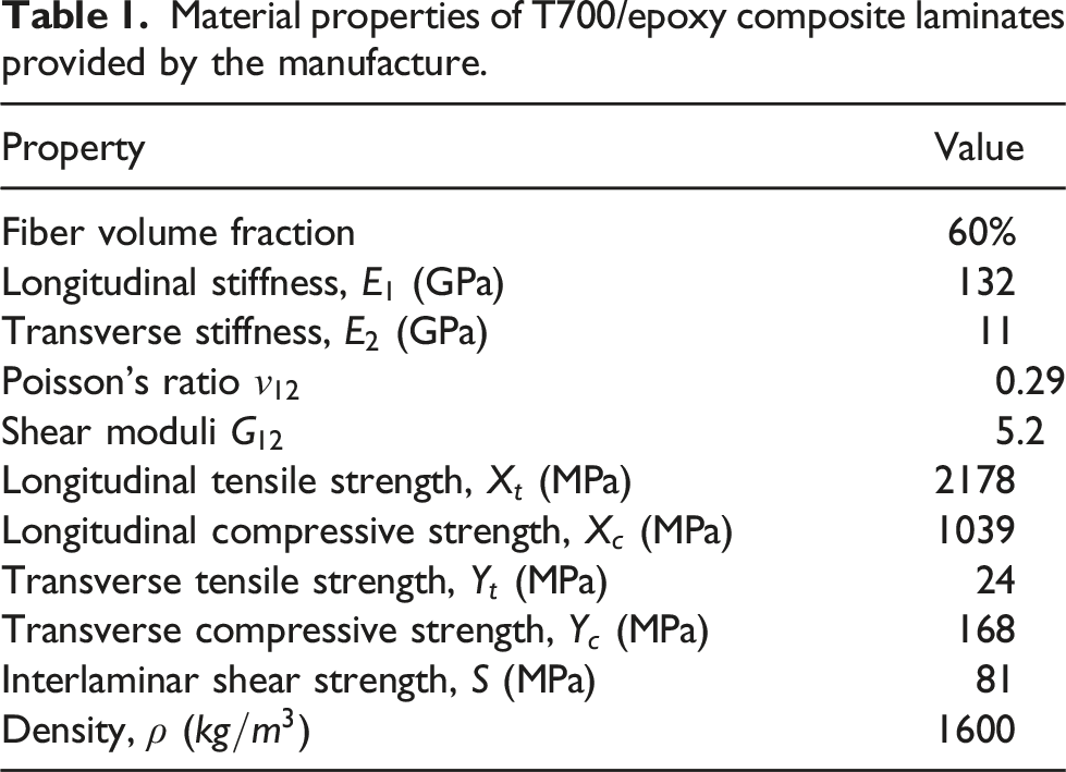
Material properties of T700/epoxy composite laminates provided by the manufacture.
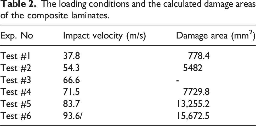
The loading conditions and the calculated damage areas of the composite laminates.
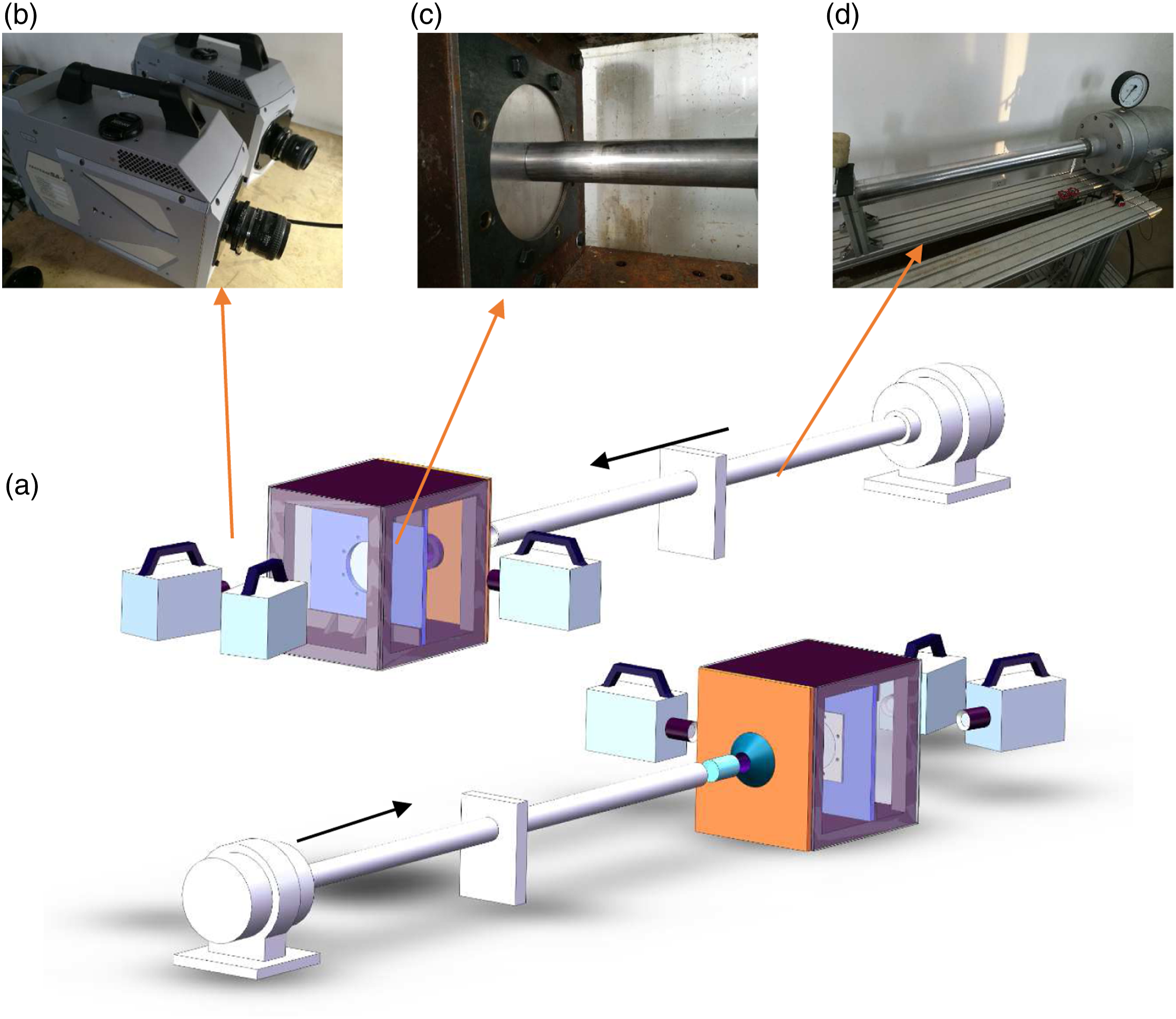
Ballistic test system (a) Schematic gas gun facilities; (b) High-speed cameras; (c) Target panel and cover plate; (d) Single-stage gas gun.
Two Photron SA-Z high-speed cameras were placed about one m away behind the targets to capture digital images for DIC calculations (Figure 2(b)). The positions of the high-speed cameras were set according to the requirement of accurate DIC calculations. The angle between them was adjusted to 17.8°. The resolutions were set to 768×888 and the shutter time were 1/31,520 s. The frame rate, defined as the number of pictures per second, was set to 30,000. These setups, along with high-strength cold light source, were modified to obtain clear shots of speckled panels without sacrificing too much brightness. GOM ARAMIS software was employed in this paper to calibrate the setups and process the DIC result. An 175 ×140 mm square GOM calibration board was used to calibrating the cameras, with a deviation of 0.074 pixels.
Results and discussions
Ice impact test
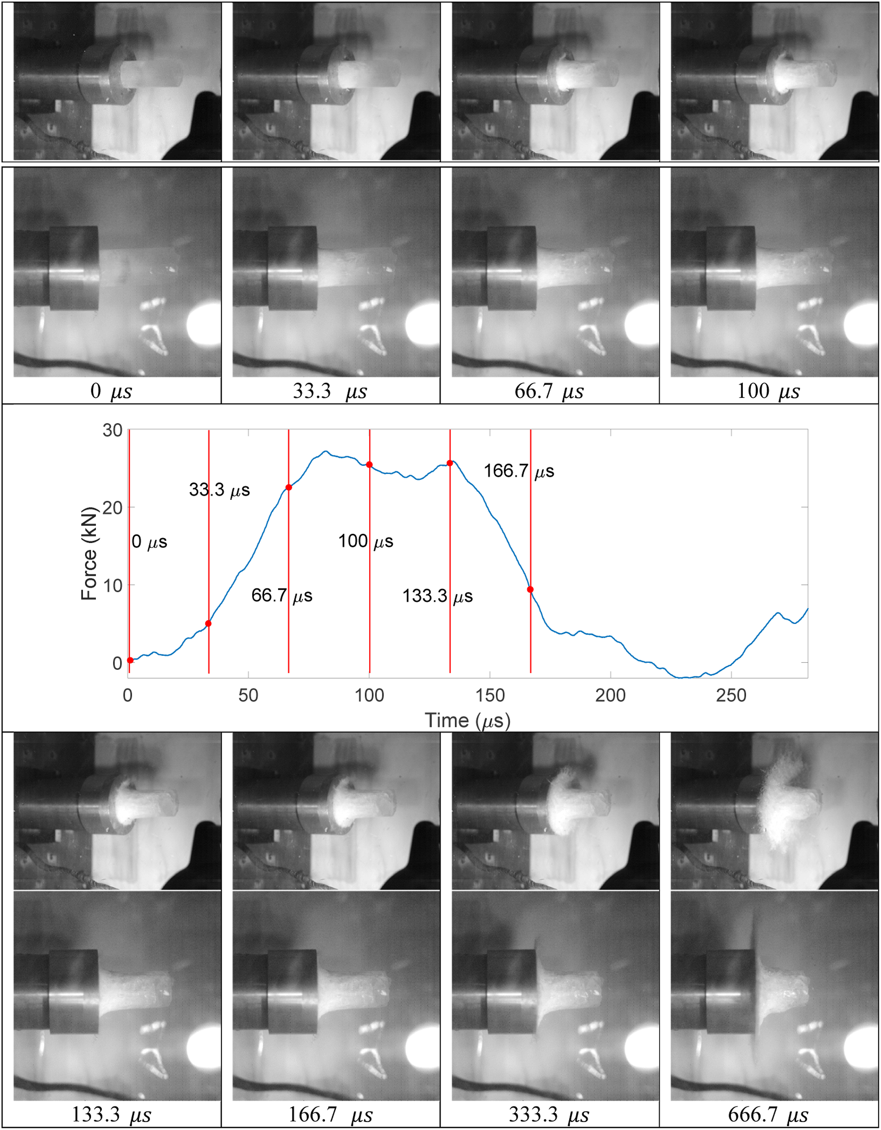
A good agreement of force signals measured by SG1 and SG2 proved that the attenuation of internal wave from SG one to SG two can be neglected, as shown in Figure 3. By combining the visual deformation process and the impact force histories, the overall dynamic behavior of ice projectiles can be observed. As an example, Figure 4 aligned the photos of the deformation process of the ice projectiles with an impact velocity of 54.4 m/s and the corresponding impact force history. As the impact proceeds, the shock wave generated at the contact interface propagates both forward and backward. The shock force exceeds the strength of ice and crushes it instantly. From the progressive transparency of the deforming ice projectile, it is observed that the degree of fragment is gradually weakened from the contact interface to the end of the projectile, which is because the internal power was released with the continuing fragmentations. The deformation and the fragmentation of such kind of projectiles can thus affect the energy exchange during the impact process, which differs from rigid projectiles where pulse loadings were produced. On the other hand, although the discussion on the differences of brittle ice projectiles and soft gelatin projectiles will not be deeply emphasized in the present paper, the force history of ice projectiles can be considered similar to gelatin ones, where an initial shock regime is generated followed by a long steady flow regime. In this example, the shock force reached its peak value at 82.1 Impact force history measured by SG one and SG two. The impact force history with an impact velocity of 54.4 m/s and the deformation process of the projectile.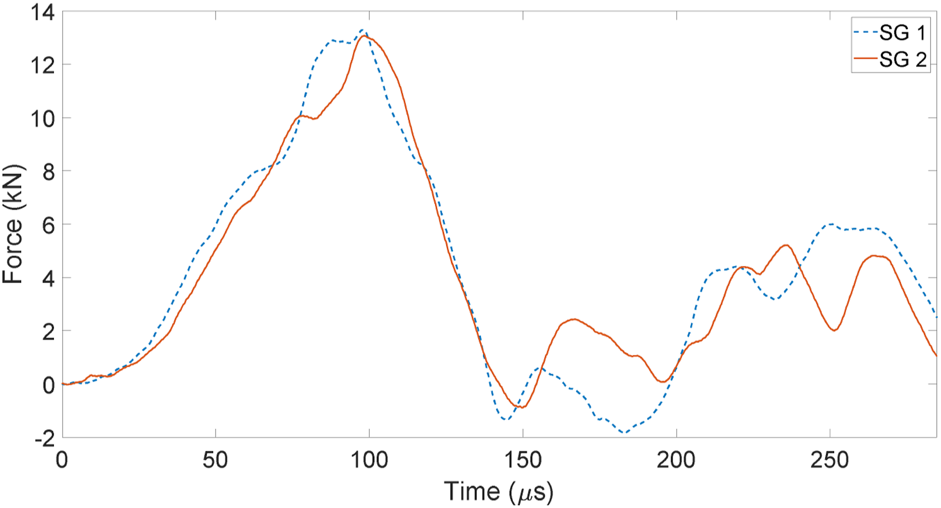
As shown in Figure 5, the peak shock forces generated in the tube sensor were linearly increased by increasing the impact energy. Note that only impact velocities were considered as the independent variable and the geometric size of the projectiles were unchanged. However, an unavoidable data scatter with an R-Square of 0.876 was observed, which was also mentioned in Jeffery.
36
There are several factors that could contribute to this phenomenon. Firstly, the ice projectiles show different dynamic properties in the brittle fragmentation processes. As a strain-rate-dependent41-43 and pressure-dependent31,44 material, the strength of ice projectiles and its debris varies largely during the impact process, resulting in scatters in the force data. Secondly, the internal residual stresses, cracks and cavities in the specimens created in the manufacture process can also affect the loading histories. Although a relatively warm temperature (about −5°C) was used to realize a slow cooling process, these defects can hardly be avoided due to the uneven outside-to-inside freezing mechanism, as stated in.
36
The third possible reason that contributes to the data scatter may be the unnecessary attack angles of the projectiles. Once the cylindrical projectile impacts on the targets with a slight attack angle, stress concentration may occur and have effect on the fragmentation, thus interfere the repeatability of this experiment. The peak impact force of ice projectiles versus impact energies.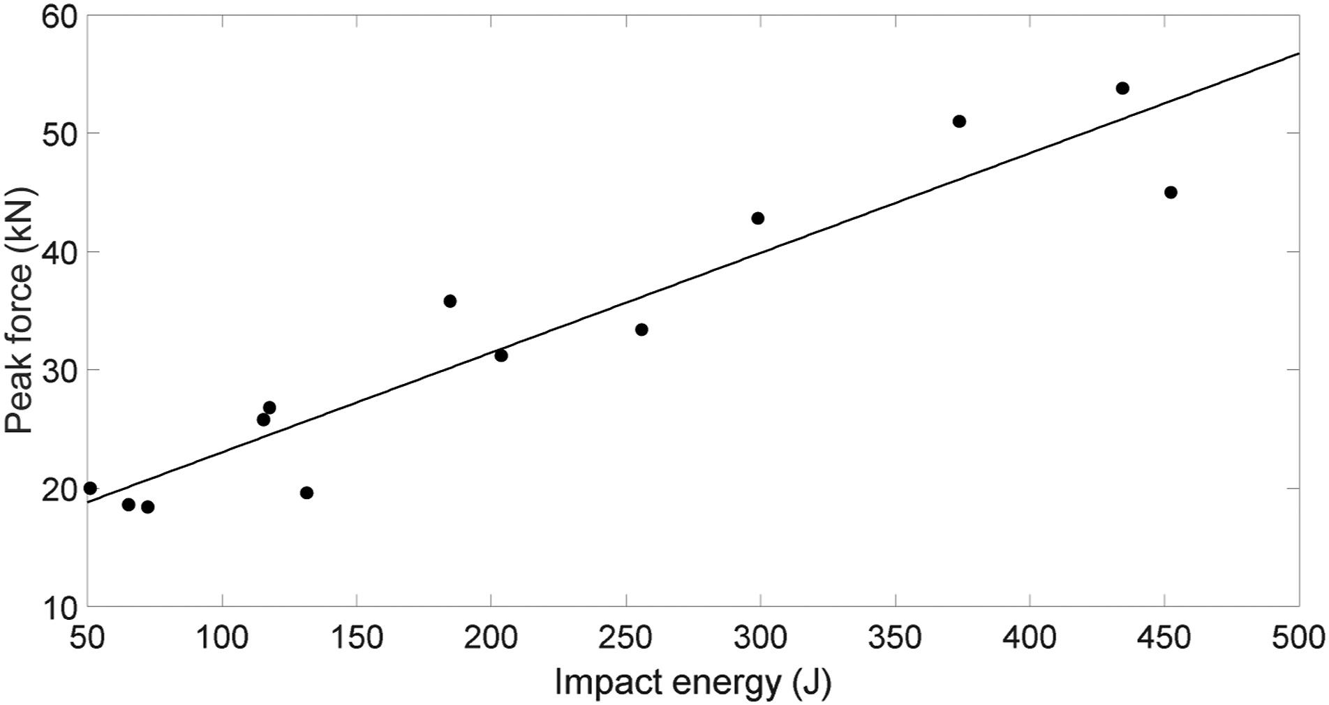
This observation therefore led to a subsequent evaluation on the repeatability of present impact loading conditions. As Figure 6 shows, after the peak pressure wave decays due to the fragmentation of the impact end, the signal rise again and reached a second and third peak created by the following body of the projectile. The impact pressure histories with different impact velocities.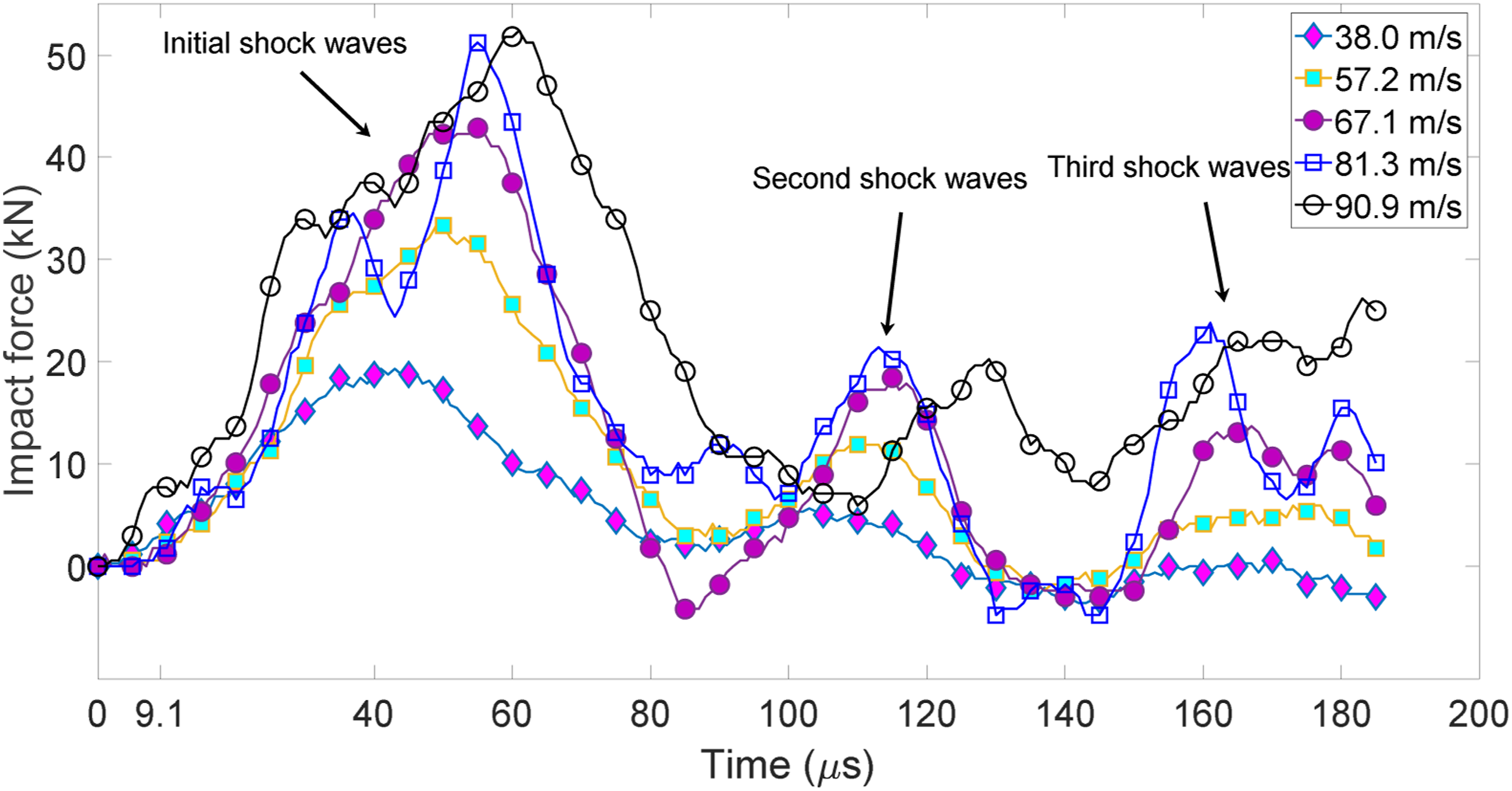
This multiple-peak-pressure effect is different from the impact behavior of soft projectiles stated by Wilbeck
1
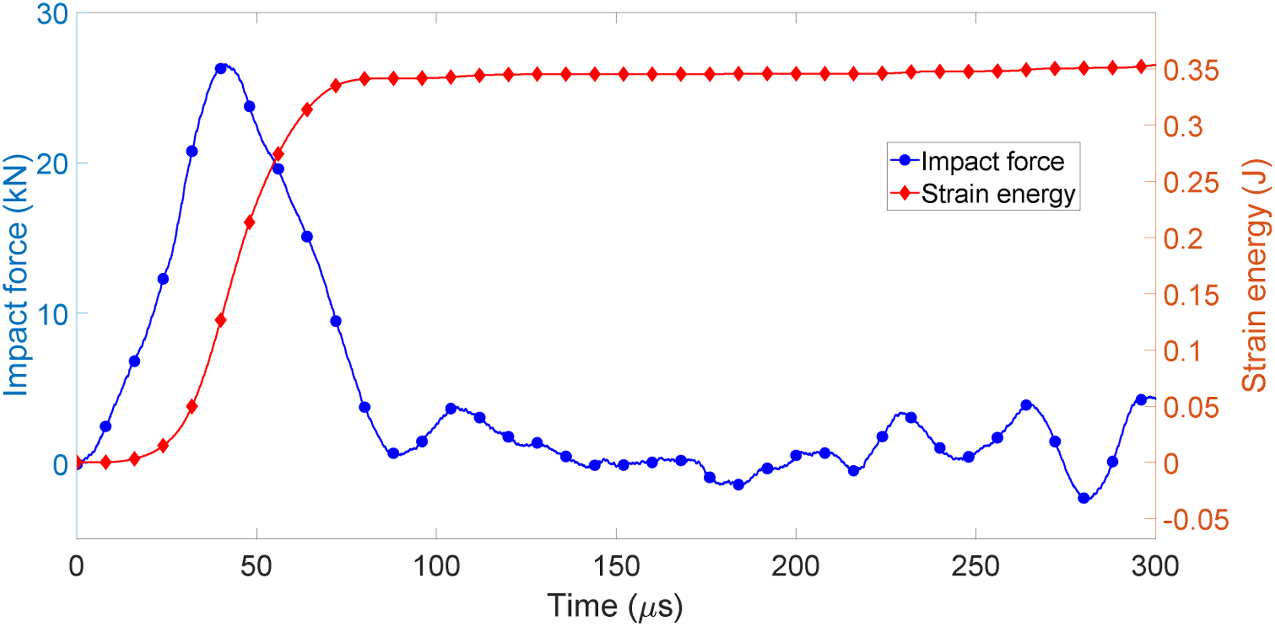
where a low steady flow pressure appears after the first shock. Also, the profiles of the pressure waves show large inconsistencies due to the unpredictable presence of fragmentations. It is therefore of interests how the impact energies were transmitted into the targets (tube sensor). The strain energies The comparison of the impact force histories and the strain energy histories transmitted in the tube sensor (51.0 m/s impact).
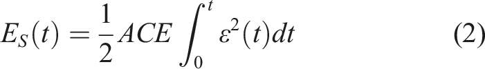
As mentioned above, the pressure signals were released by the backward tensile waves at 285 The strain energies transmitted into the tube sensor versus impact energies.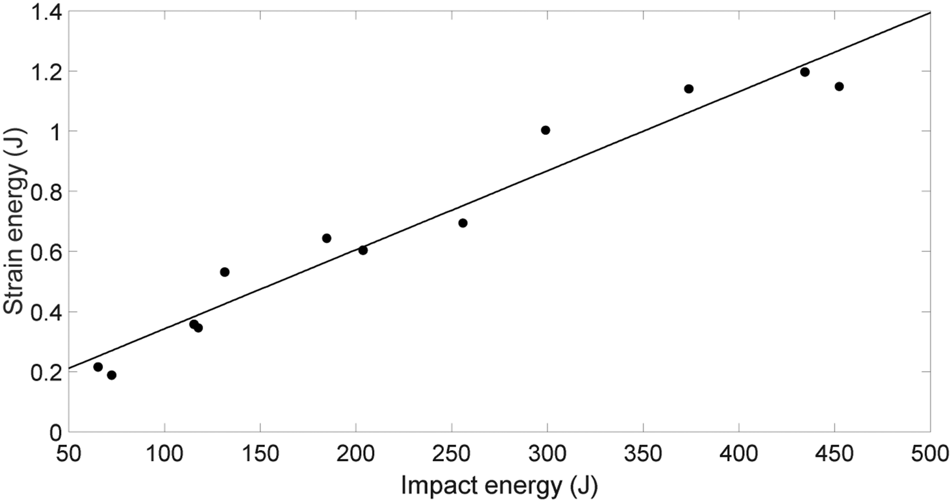
T700/epoxy laminates impact tests
The impact velocities and final damage areas on the laminates are listed in Table 2. For each impact conditions, one test was conducted. The impact responses of T700/epoxy laminates subjected to ice projectiles are different from classical rigid impact on metal targets. As the contact areas are highly dissipated during the fragmentation process, and the impact duration is relatively long compared to rigid projectiles, gentle and continuous impact loadings may be generated. Also, although the T700/epoxy laminates have high in-plane strength and stiffness, they are vulnerable when subjected to transversely impact loadings. Matrix cracks and delamination may occur even with soft projectile impacts, which can play a role in energy absorptions. Third, the contact area may expand largely in the impact process, thus results in time-dependent distributed loadings. One of the consequences of these factors is that the residual bulges were hardly observed on the post-test specimen. It can be seen from Figure 9 that only slight fiber breakages were observed in the impact surface. The visible damage on the surface of the specimen (impact velocity 83.69 m/s).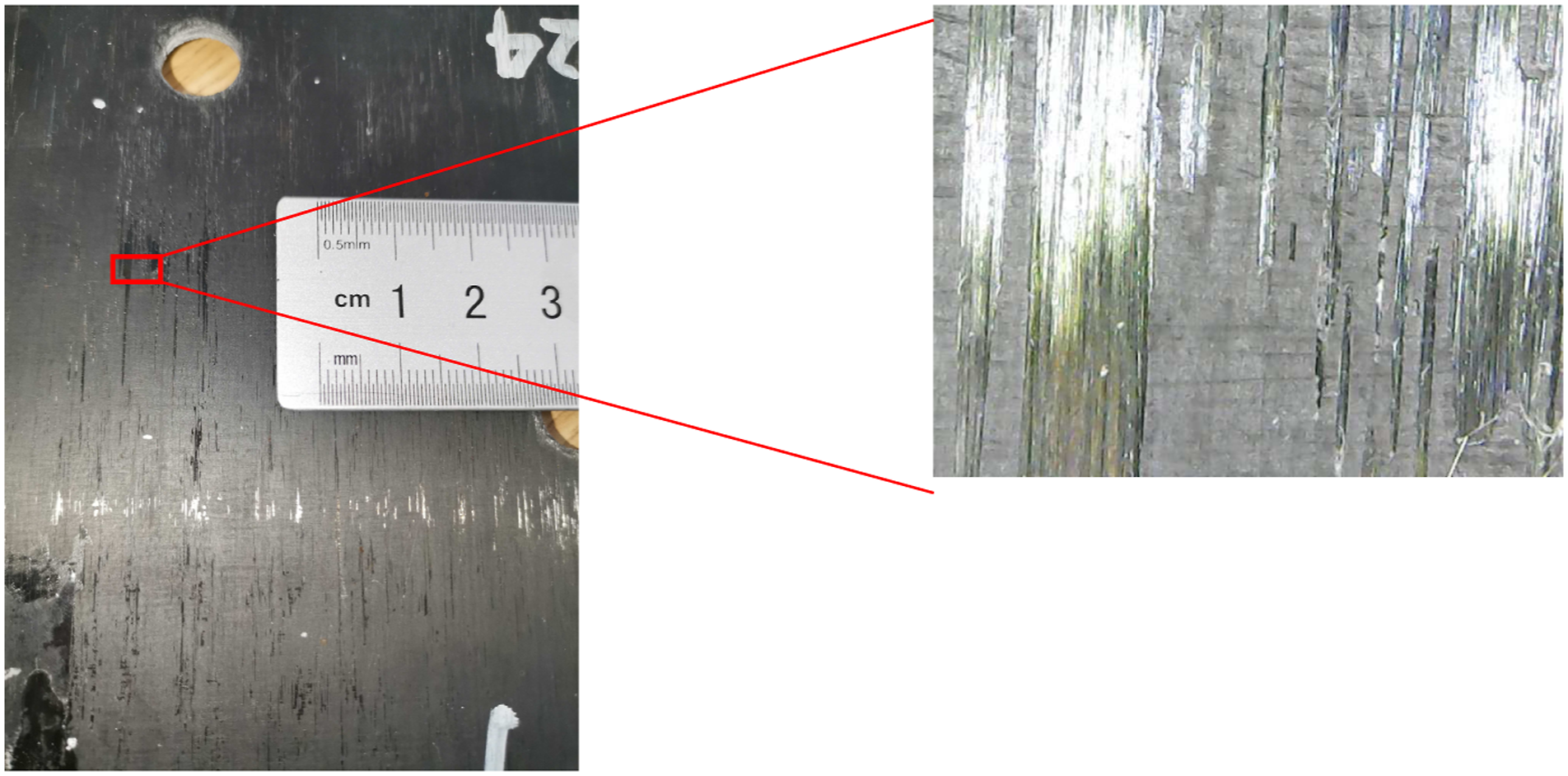
The post-impact coupons were cut through their central sections to observe the internal damage. From Figure 10 we can see that delamination is the major damage mode. These pictures were taken at different locations, and the delamination occurred at random interfaces for different impact velocities. The first picture shows the specimen which was impacted with a 37.8 m/s ice projectile, where no damages were visually found. However, considering the highly distributed impact loadings and responses of the targets, it should also be noted that the level of damage observed in these pictures can only been treated qualitatively. The more global judgment will be discussed in the following C-scan results. The sectional views of the specimens and delaminations (yellow arrow).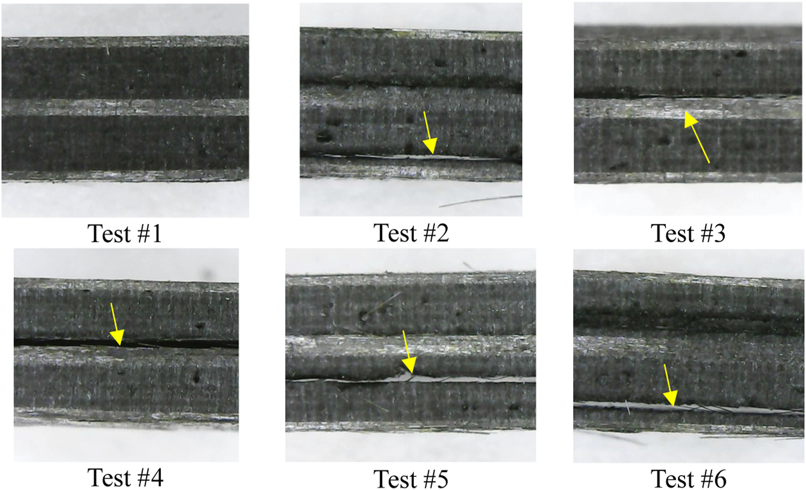
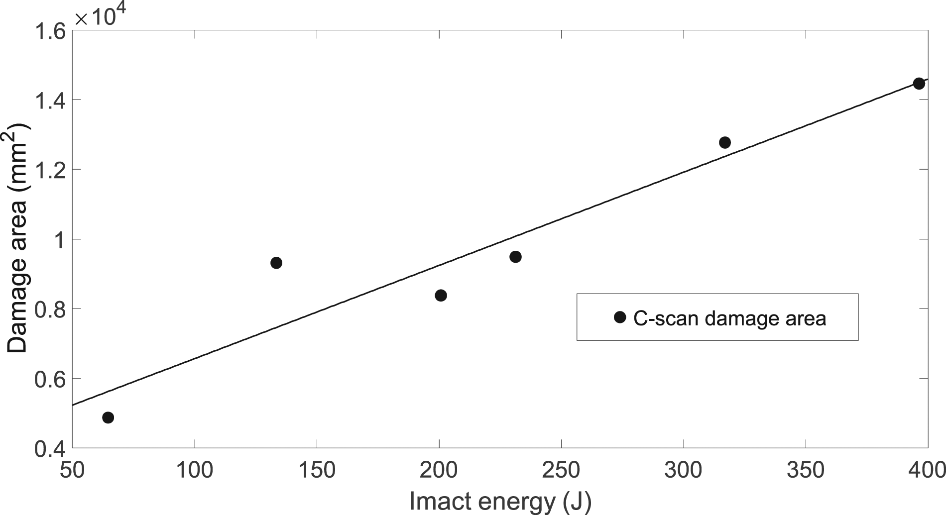
The damage areas of the post-impact laminates measured using C-scan techniques are listed in Table 2. The level of damage on the laminates can be approximately examined by comparing the highlighted areas of C-scan results shown in Figure 11. A positive correlation between the damage level and the impact energy were observed, see Figure 12. Upon each C-scan result, the peak bulge shape measured using DIC techniques was also presented. Below 71.5 m/s, the bulges were almost circular. Despite of the anisotropic material used in the laminates, the uniformly configurated layers share the loads in different directions. However, when the impact velocities were high (83.7 m/s and 93.6 m/s), severe damage occurred and the bulge shape became non-symmetric. The peak bulges measured with digital image correlation method and their post-test C-scan results. The damage (delamination) areas calculated using the C-scan results versus impact energies.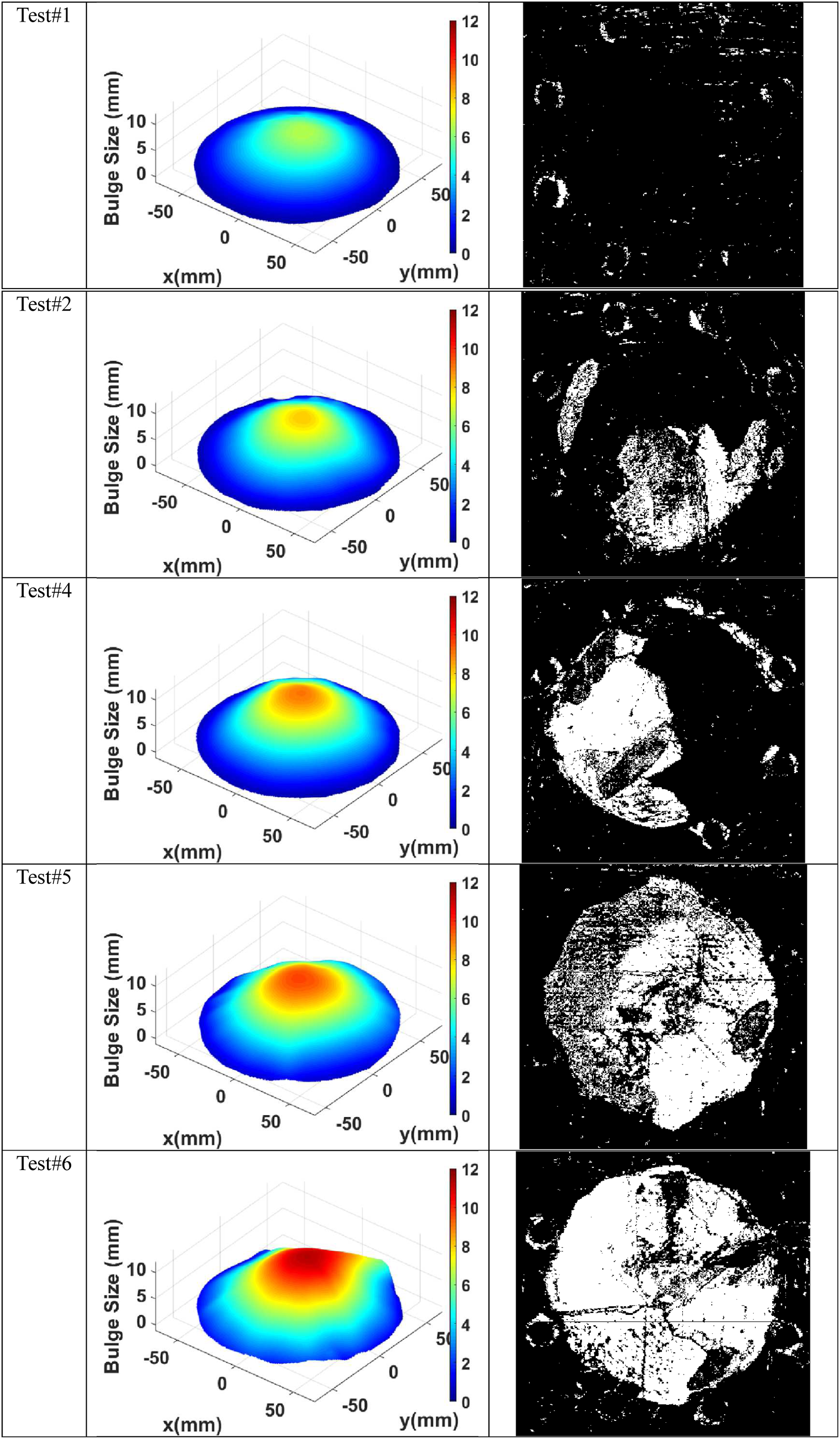
The deflection histories of different points on the target may help to analyze its deformation process. Four points were seeded on the bulge to extract the deflection data, which were 0 mm (p#0), 20 mm (p#1), 40 mm (p#2), and 60 mm (p#3) away from the central points, respectively. Among these results, the laminates subjected to the lowest (37.8 m/s) and the highest (93.6 m/s) velocities’ impact are shown in Figure 13. In the former one, the deflections dropped to below 0 mm after the initial peak values and then vibrated as the impact continued. Also, for the points farther from the central point, the deflections were less violent. However, the signals did not return to 0 mm after the peak value in the latter plots. In fact, a residual bulge appeared in the post-impacted laminate and recovered in about 5 min. This kind of macroscopic “elastic recover” is clearly different from that in metal materials. The matrix cracking and delamination led to internal slips and dislocations, which generated resistance force when the bulges started to shrink, resulting in slow recover processes. The deflection histories of four points on the central section: p#0 (center point), p#1 (20 mm from the center), p#2 (40 mm from the center) and p#3 (60 mm from the center) for Test #1 (a) and Test #6 (b).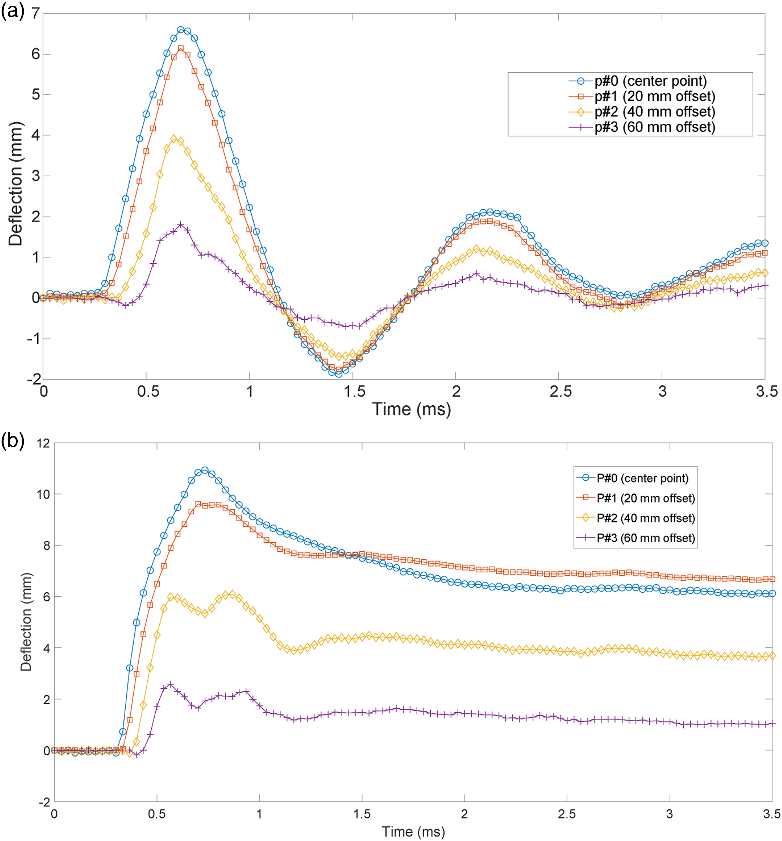
Another phenomenon shown in Figure 13(b) is that the peak point shifted from the central point p#0 to p#1 in the continuously loading process, which means that the deformation of the target was no longer uniform and symmetric. This can also be observed in test #5. As the impact velocity was increased, more internal damages were generated in the laminate, and its influence on the dynamic response of the laminate was increased. When the impact energies were low, the laminates were able to maintain its quasi-isotropic properties and the deformations were symmetric. As the impact energies were increased, the integral properties of the laminates were broken and the anisotropic nature of individual layers began to dominate due to significant delaminations, and the deformation became irregular.
The entire deformation process of the laminate subjected to 93.7 m/s ice impact can be shown in Figure 14 by combining the displacement histories, the bulge shape and the section shape. The dashed line indicated the extracted section during the DIC processing along with the spine of the biased bulge. Eight points in timeline were extracted to record the DIC full-field results and the section curves. Before 0.6 ms (first ∼ fourth picture), the bulge showed circular and the section was symmetric. After the fifth picture, the bulge shape became irregular and the peak point started to drift. Meanwhile, the bulge shrank with a very slow speed and eventually disappeared. A conclusion can therefore be made that the impact of ice projectiles may cause zero bulges on the laminate targets, but their natural quasi-isotropic properties could be significantly changed with randomly distributed inner damages. The deformation process of the bulge (Test #6) characterized by the 3D-DIC colormaps and the central section profiles.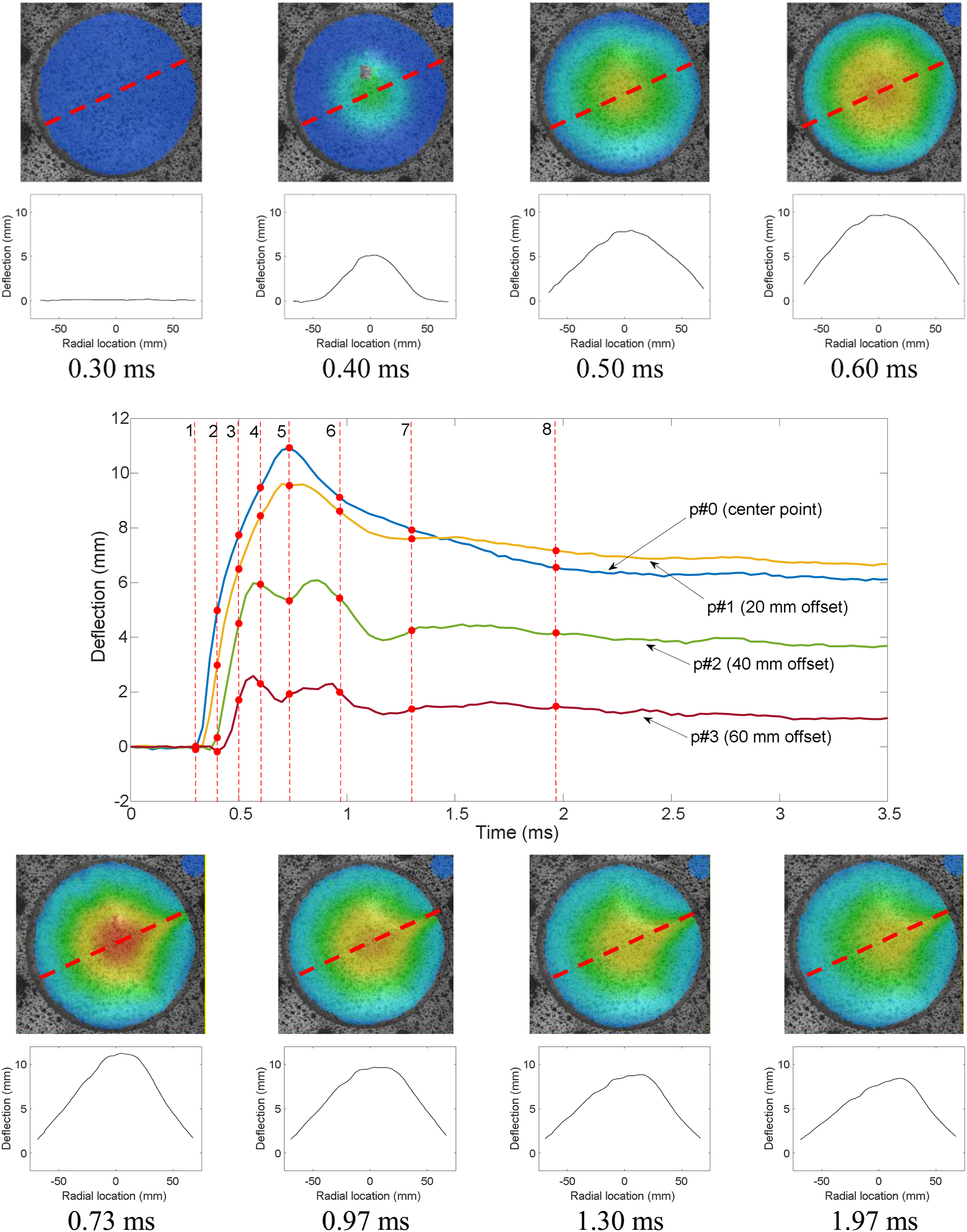
Conclusions
As different types of composite materials have been widely employed in aircraft industries, the interests of their impact resistance have been increasingly enlarged. According to typical environmental conditions of aircraft during flight, the presented study recommended a comprehensive experimental method for evaluating the dynamic responses of CFRP laminates subjected to ice impact. First, the impact force of ice projectiles was measured by a hollow tube sensor, where the impact process was visually observed using high-speed cameras. Then the ice projectiles were used to test the impact response of T700/epoxy laminates. The deformation processes of the targets were recorded by two cameras with 3D-DIC techniques and the damage state of the laminates were measured using C-scan techniques.
With the images captured by the high-speed camera, the deformation of the projectiles and the flow process of their debris were observed combining with the corresponding force histories. Their highly distributed and non-uniform impact loadings on the expanding contact areas are differed from conventional rigid projectiles. The inevitable scatters on the impact force results with an R-square of 0.876 can be attributed to the internal defects in the forming process, the dynamic strengthening, and the attack angle while impact proceeding. Based on the strain and stress data obtained by the strain gage, the strain energies transmitted into the tube sensor was calculated and compared. The positive correlations between the strain energies and the initial kinetic energies showed good convergency, which confirmed the repeatability of the loading conditions for following impact tests. The collected force histories and real-time images can also be used as reference data for future numerical studies.
Six T700/epoxy composite laminates were impacted by the ice projectiles with different velocities ranging from 37.8 m/s to 93.6 m/s. The 3D-DIC technique with two cameras behind the targets and ultrasonic C-scan technique were, respectively, used to measure the transient deformation process and the post-test internal damage of the targets. With low-impact velocities, the target laminates vibrated around its initial locations with symmetric deformations as the impact proceeded. Although the bulges became non-symmetric for high-velocity impacts as irregular-distributed delaminations significantly affected the quasi-isotropic properties of laminate targets. Within the impact velocities used in the present study, the major damage mode created by the ice projectiles were invisible delaminations and cracks instead of bulges, fiber breakages, or external damage, which can be a reference for adjusting the aircraft routine performance evaluation.
Footnotes
Acknowledgments
The author would like to thank the National Natural Science Foundation of China (NSFC, No.: 11872021) and the Harbin FRP Institute for continuous support of this project
Declaration of Conflict Interest
The authors declare that they have no known competing financial interests or personal relationships that could have appeared to influence the work reported in this paper.
Funding
The author(s) received no financial support for the research, authorship, and/or publication of this article.