
Abstract
Fiber length and interfacial bonding properties are important factors in determining the mechanical properties of the composites. As an emerging fiber-reinforced thermoplastic molding method, DFFIM can reduce the fiber breakage during the molding process and thus improve the mechanical properties, while the fiber length and interfacial bonding properties of the composites fabricated by DFFIM are mainly affected by the equipment structure. This paper takes nozzle as the research object to investigate the effect of nozzle on the properties of glass fiber reinforced polypropylene (GF/PP) fabricated by DFFIM. First, GF/PP composites at three positions of nozzle flange, nozzle air-injection outlet and mold cavity were selected for fiber length detection, and it was found that the nozzle would lead to more severe fiber breakage in GF/PP composites; POLYFLOW was subsequently used to analyze the shear stress of GF/PP mixed flow fields in different aperture nozzles; DFFIM experiments were carried out to analyze the fiber length, micromorphology, and mechanical properties of GF/PP composites using the nozzle aperture as the test factor, and the results were consistent with the simulation results, as the nozzle aperture increased, the fiber length and interfacial bonding properties of GF/PP composites gradually increased, hence improving the mechanical properties.
Keywords
Introduction
With the increasing demand of the automobile industry, using high-performance composites to replace metals for lightweight has gradually become the main development direction of modern manufacturing. Fiber-reinforced thermoplastics (FRTP), as structural composites, are widely used in the aerospace, automotive, construction, and chemical industries with the advantages of high strength, low density, corrosion resistance, and a wide selection of resin matrix, taking the thermoplastic resins with high toughness and low modulus as the matrix phase, and fibers with high strength and high modulus as the reinforcing phase.1–3 The common molding processes for FRTP include compression molding, pultrusion, and injection molding, among which injection molding has become the main molding method due to its high degree of automation and strong product stability.4–6 As an emerging injection molding method for FRTP, Direct Fiber Feeding Injection Molding technology (DFFIM) adopts an improved two-stage screw and a barrel with a fiber feeding port, and the continuous fibers are fed directly from the fiber feed port, mixed with the molten material plasticized by the first-stage screw on the second-stage screw, and finally injected into the mold, which not only has the advantages of easy processing, simple operation, pollution reduction, and efficiency, but also can flexibly adjust the type and proportion of fibers and matrix according to the use demand. Compared with the traditional “two-step” method of first granulation and then injection molding, DFFIM technology avoids the limitation of the fiber length by the pellet, reduces the shear action on fibers, and ensures the residual fiber length in the composite, so that the composite has better mechanical properties.7–10
The mechanical properties of FRTP fabricated by DFFIM are closely related to many factors such as fiber length, fiber content, and interfacial bonding properties, which are mainly determined by DFFIM process parameters and equipment structure, and many scholars have conducted relevant research. Nakao et al. found that CF/PA6 composites fabricated by DFFIM had better properties compared to the granulation method, but the fiber distribution uniformity decreased with the increase of fiber content, and the interfacial bonding properties decreased. This is a disadvantage of DFFIM technology, and improving the interfacial bonding properties of DFFIM formed composites through screw design and other methods is a very important research direction. 11 Mathurosemontri et al. investigated the effects of matrix feeding rate, screw rotation speed, and plasticizing temperature on the properties of GF/POM composites fabricated by DFFIM, and the results showed that increasing the feed rate of the resin matrix could increase the fiber content of the composites, thereby improving the mechanical properties. However, the fiber length and dispersion uniformity decreased with the increase of fiber content and screw speed, which could be improved by increasing the barrel temperature. 12 Yuuki et al. found that adding a small amount of carbon fiber to GF/ABS composites fabricated by DFFIM could significantly improve the mechanical properties, but carbon fibers were more prone to agglomeration, which in turn affected the enhancement effect of mechanical properties. 13 Yajun Zhang et al. found that increasing the injection pressure appropriately could increase the fiber length of the composites and make the fiber and matrix more tightly combined, but excessive injection pressure would cause the fiber to be subjected to excessive shear action when passing through narrow channels such as gates, resulting in a decrease in the growth trend of the composite mechanical properties. 14 Fiber breakage phenomenon was closely related to the screw structure, especially the characteristics of the compression zone was an important factor affecting the fiber length. 15 Akira Inoue et al. indicated that the mechanical properties and stability of FRTP were related to the residual fiber length and fiber dispersion uniformity, while the fiber length and dispersion uniformity were negatively correlated, and V&D screw with Dulmadge and variable-pitch characteristics could overcome this conflict and improve both properties simultaneously. 16 Of course, special mixing elements could also be set at the end of the screw metering section to ensure the fiber length and dispersion in FRTP, and even change the “skin-core” structure composition of the composite, thereby improving the mechanical properties of FRTP. 17 Lafranche et al. pointed out that fiber length was an important determinant of the composite mechanical properties, and the residual fiber length could be further improved by reducing the shear stress on the melt during the plasticization stage, such as reducing the screw compression ratio, setting longer melt zone, and increasing the melt channel of the check ring. 18 Xiaofei Yan et al. prepared DFFIM samples using two different sets of check rings and molds. The effect of the check ring gap and mold structure on fiber breakage was assessed by measuring the fiber length, and it was concluded that the check ring with larger gap and the mold with larger gate were beneficial for fiber length retention in polypropylene-glass/basalt fiber hybrid composites. 19 Thodsaratpreeyakul et al. used the DFFIM process with improved and normal check rings to prepare GF/PET composites and found that the composites fabricated by improved check ring with larger runner gaps had fiber length distribution in the range of 0–8000 µm and had better impact properties, whereas the composites fabricated by normal check ring had fiber length distribution in the range of 0–3800 µm. 20 In summary, optimizing the molding process parameters and equipment structure can enhance the mechanical properties of the composite by increasing the effective fiber length and interfacial bonding properties. Previous scholars have conducted extensive research on the effect of molding process parameters on the properties of the composite fabricated by DFFIM, while the research on DFFIM equipment structure mainly focuses on screw and mold structure, and there is almost no research on the effect of nozzle structure on the composite properties.
As an important component connecting the plasticization unit and mold runners, the nozzle will have a strong shear action on the melt flowing through it. Studying the effect of its structure on the properties of composites fabricated by DFFIM has great significance for the application of DFFIM technology. Therefore, the nozzle aperture was selected as the experimental test factor in this paper to investigate its effect on the properties of the composites fabricated by DFFIM. Firstly, GF/PP composites at the nozzle flange, nozzle air-injection outlet, and mold cavity were selected for fiber length detection, and the effect of nozzle on glass fiber length was studied. Then POLYFLOW was used to simulate the nozzle flow channel numerically, and the effect of nozzle aperture on the properties of GF/PP composites was investigated by analyzing the shear stress. Finally, the nozzles with different apertures were used as experimental variables to prepare GF/PP composites. By detecting the fiber length and mechanical properties of the composites, and combining with SEM micrographs, the effect of nozzle aperture on the properties of GF/PP composites fabricated by DFFIM was analyzed, and the POLYFLOW simulation results were verified.
Experiment and simulation
Materials
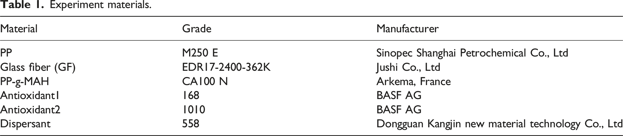
Experiment materials.
Equipment
The injection molding machine (TTI-90F2) provided by Donghua Machinery Co., Ltd and the DFFIM special plasticizing unit were used as experimental equipment. The modified injection molding machine is shown in Figure 1. TTI-90F2 injection molding machine equipped with DFFIM plasticizing unit.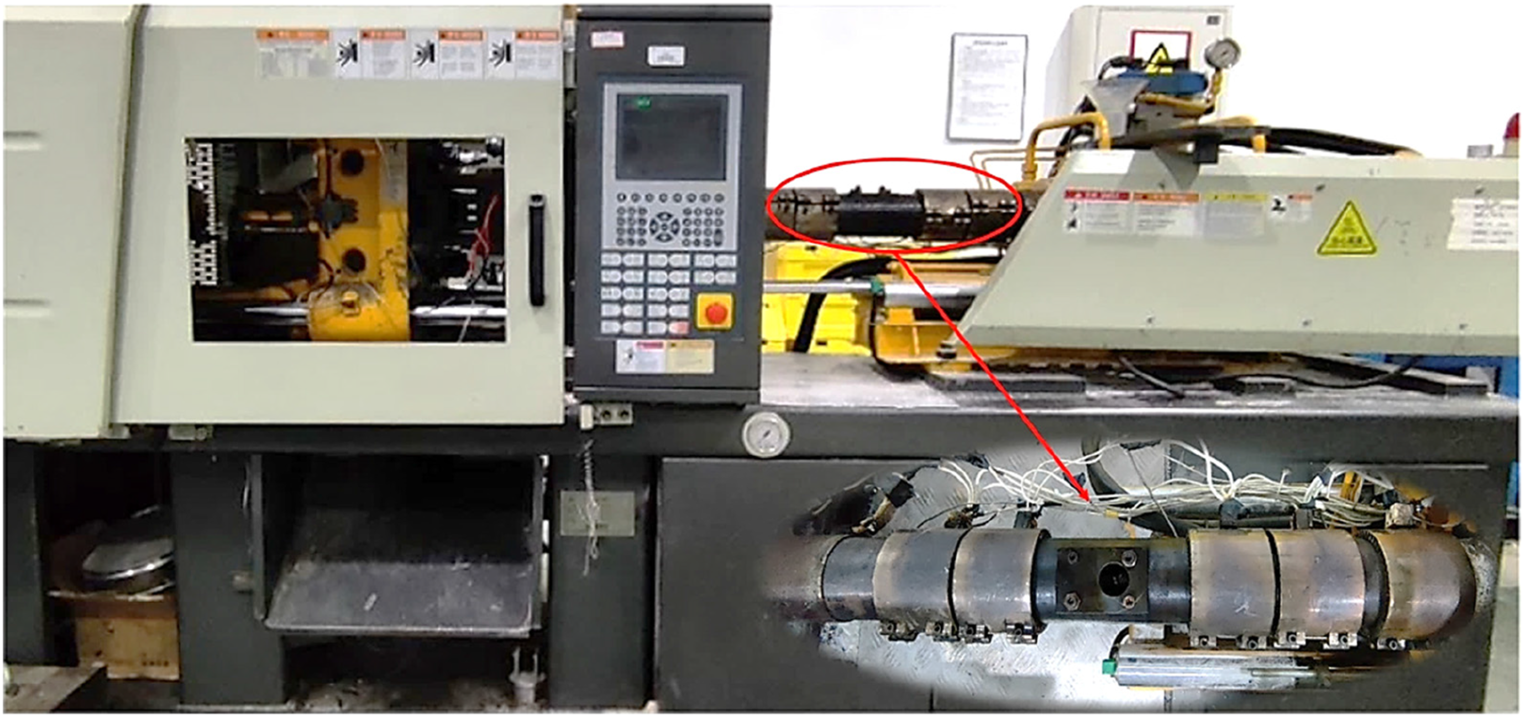
Nozzles with apertures of 2 mm, 3 mm, 4 mm, and 5 mm as shown in Figure 2 were selected to complete the preparation of GF/PP composites. Different aperture nozzles.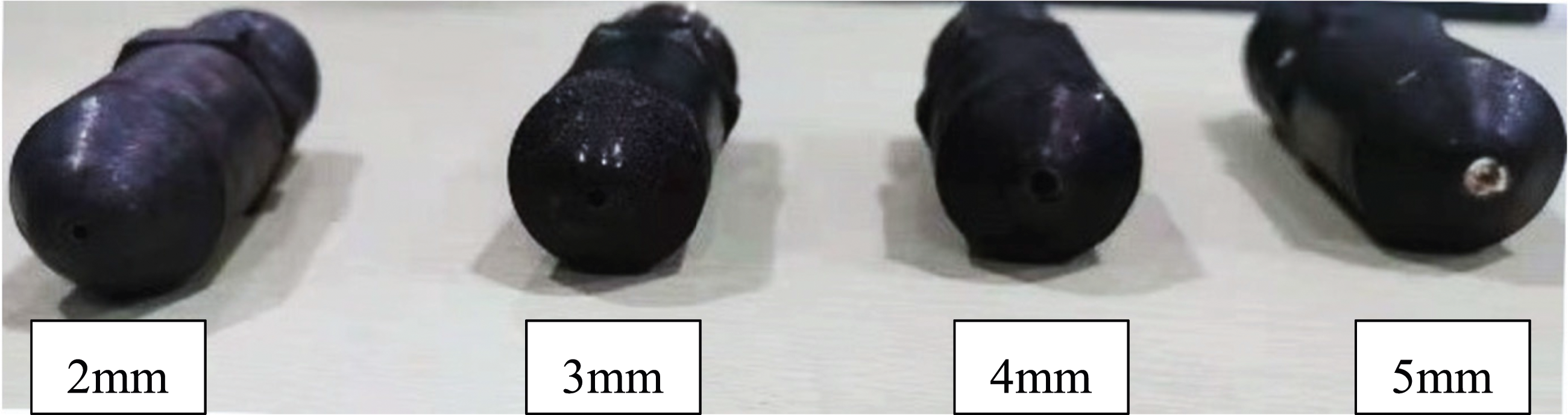
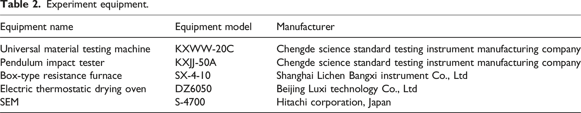
Experiment equipment.
Simulation
Basic assumption
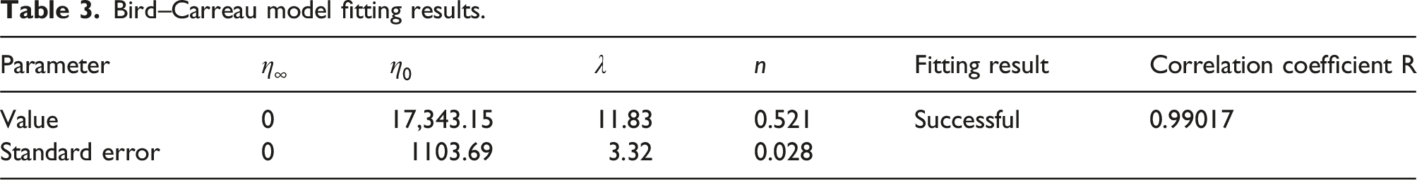
Basic assumptions have been made based on the GF/PP flow field: (1) Bird–Carreau constitutive model is selected; (2) Gravity and inertial forces are much smaller than viscous forces and are negligible; (3) The flow field is an isothermal stable flow field, which is regarded as laminar flow; (4) There is no slippage in the flow field wall, and the GF/PP fluid is incompressible.
Mathematical equation
The fluid is assumed to be isothermal, and the fluid motion in Cartesian coordinate systems should satisfy the equations of conservation of mass and conservation of momentum.
Conservation equation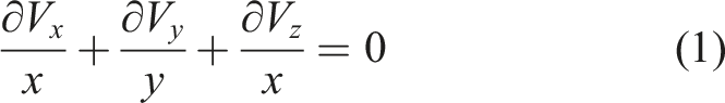
Momentum conservation equation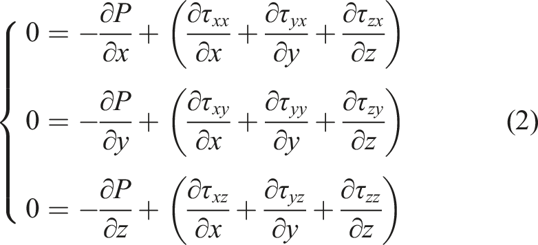
The constitutive model uses the Bird–Carreau model, which is expressed as
Finite element model
To describe the flow field inside the nozzle, Solidworks was used to create a 3D model of the nozzle and flow channel. The 3D models of the nozzles and channels were meshed into x_t files using the preprocessor mesh module of Workbench. The meshing finite element models are displayed in Figure 3. Nozzle and nozzle channel meshing finite element models.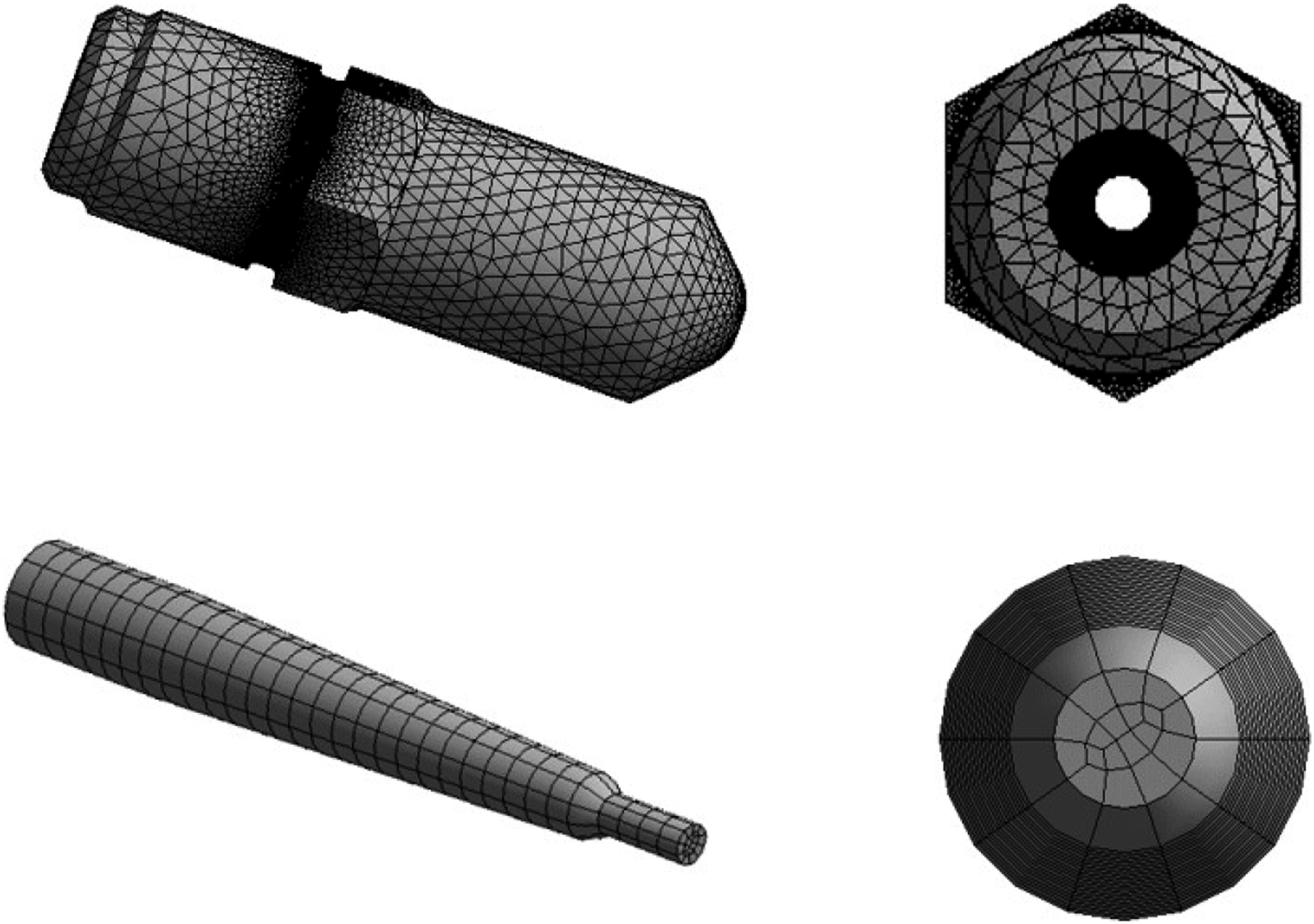
The boundary conditions for the nozzle flow path are set according to the actual processing parameters and basic assumptions.
Nozzle inlet: inlet set at a pressure of 100 MPa.
Nozzle outlet: outlet set to Outflow.
Nozzle inner surface: no slip on the wall,
The rheological test of GF/PP composites
The GF/PP composites were cut into discs with a diameter of 20 mm and a thickness of 3 mm, and rheological experiments were performed using the TA HR2 rotational rheometer manufactured by America at a test temperature of 250°C. The results are presented in Figure 4. Rheological experimental results of GF/PP composites.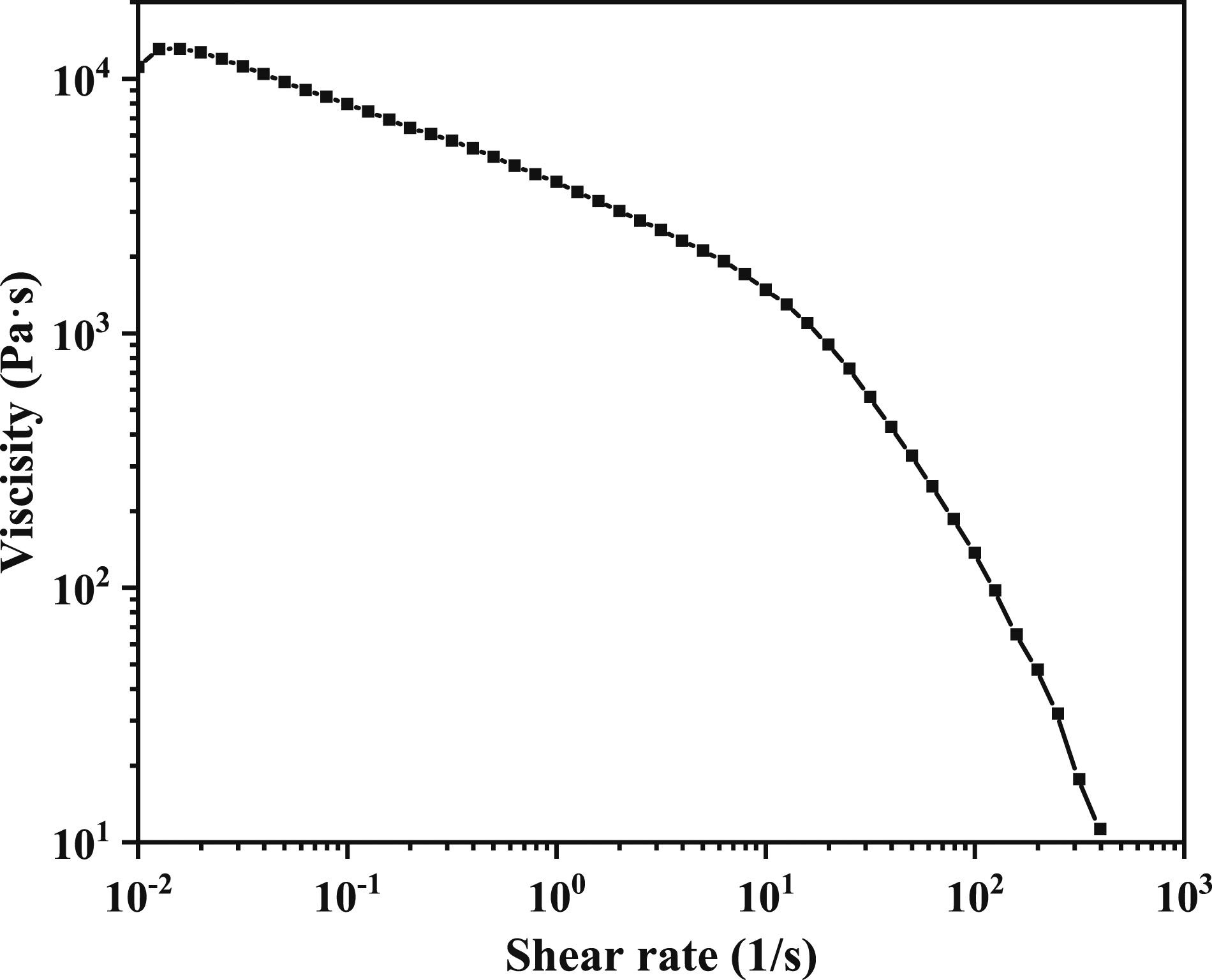
Bird–Carreau model fitting results.
Specimen preparation
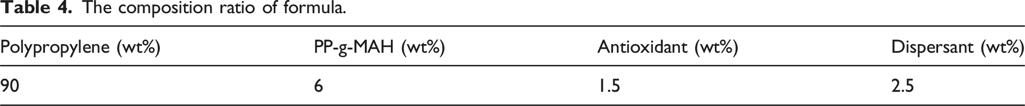
The composition ratio of formula.
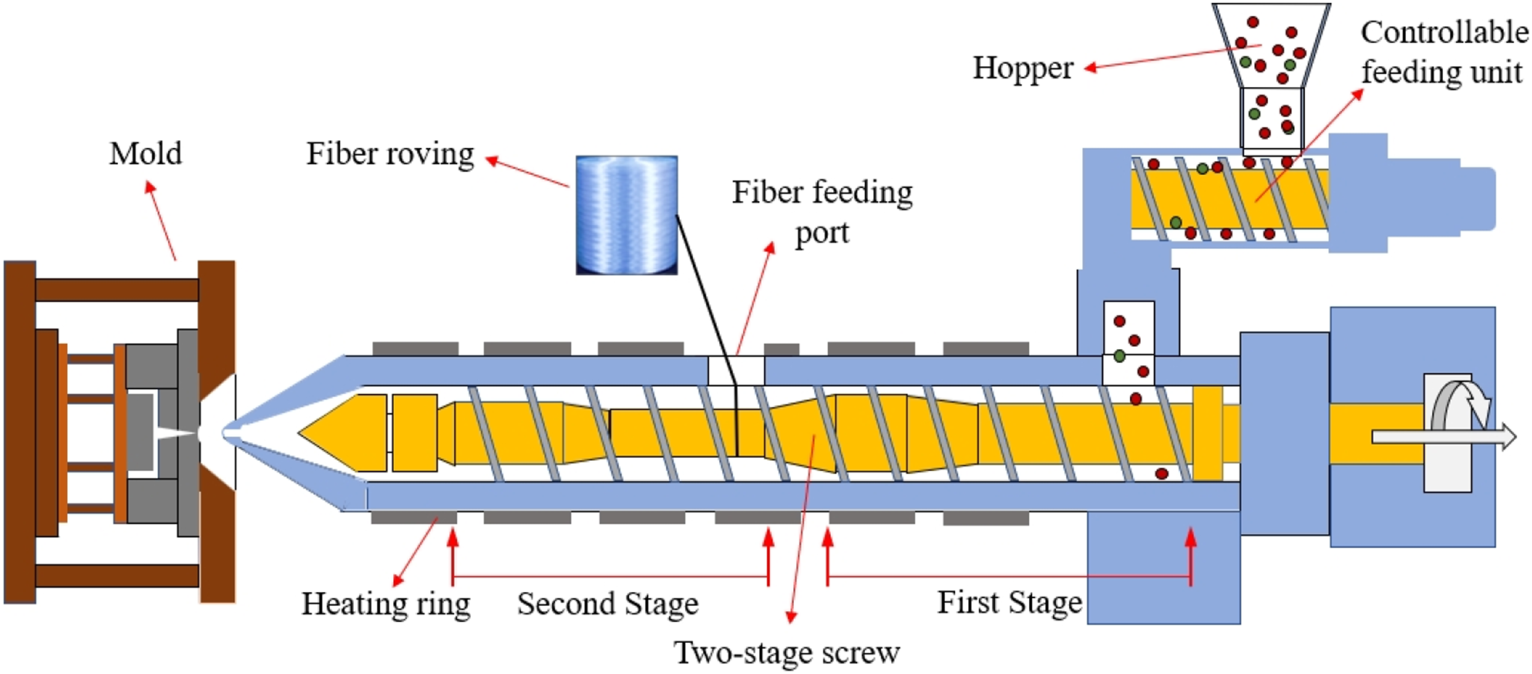
DFFIM processing schematic.
Under the process parameters of screw speed of 15 r/min, plasticizing temperature of 250°C, injection pressure of 100 MPa, and injection speed of 15 mm/s, standard sample strips were prepared, and GF/PP composite samples were selected at the nozzle flange and nozzle outlet. The GF/PP composite samples obtained by air-injection at the nozzle flange and the nozzle are presented in Figures 6(a) and 6(b), and Figure 6(c) shows the standard sample strips. GF/PP composite samples at three locations during the injection process. (a) Nozzle flange air-injection samples; (b) Nozzle outlet air-injection samples; (c) Standard sample strip.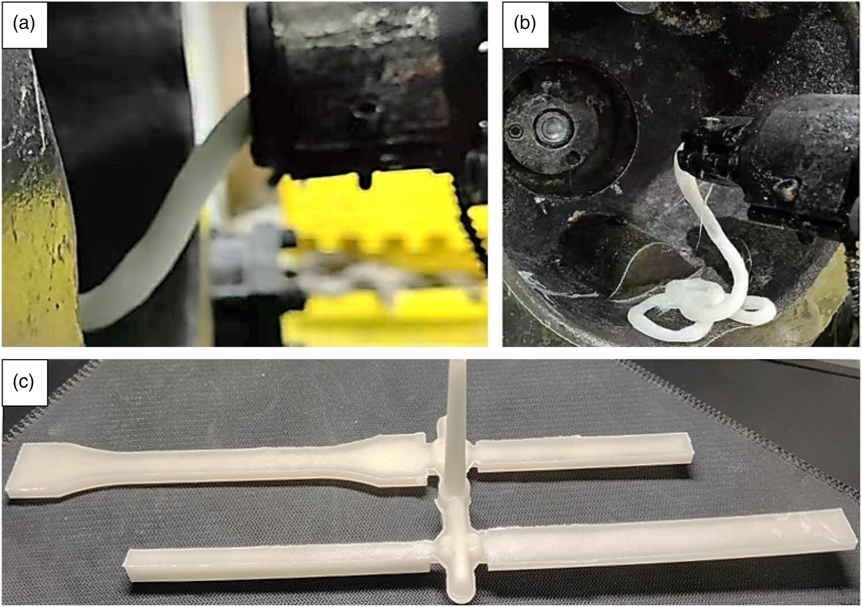
Testing and characterization
The GF/PP composite was calcined in a muffle furnace at 600°C for 4 h until the PP was completely decomposed, and the remaining part was gently stirred in a beaker filled with purified water to obtain a glass fiber suspension. The suspension liquid is placed in a clear glass dish and dried thoroughly, so that the glass fiber is attached to the bottom of the glass dish to obtain a sample for glass fiber length detection. The images were processed with the software Image-pro-plus to measure the fiber length. Average length of glass fiber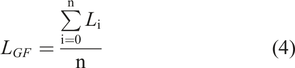
The GF/PP composite was fractured using liquid nitrogen to obtain a fracture cross section and was attached to the side surface of the carrier plate with conductive adhesive. Due to its poor conductivity, silver glue was required before gold spraying could be carried out. The distribution of glass fibers in the PP matrix and the interfacial bonding was evaluated by observing the microscopic morphology of the sample cross-sections using scanning electron microscopy (SEM).
Tensile strength, bending strength, and unnotched impact strength were tested according to GB/T1451-2005. In order to reduce the testing error, five samples were selected as a group for mechanical property testing, and the processing conditions of each group were the same.
Results and discussion
Effect of nozzle on the fiber length during injection molding process
The distribution of the glass fiber length and the average glass fiber length for nozzle flange, nozzle outlet, and mold cavity samples are shown in Figure 7. The percentage of the fiber length greater than the 5 mm at the nozzle flange and nozzle outlet is the highest, accounting for 69.48% and 67.84% of the total number of fibers, respectively, which is much higher than the 5.97% at the mold cavity. And the proportion of short glass fibers less than 3 mm in the mold cavity is as high as 78.89%, resulting in its average glass fiber length of only 2.25 mm. This result can be expected because the fibers are subjected to strong shearing action when passing through the narrow mold runners and gates, resulting in severe fiber breakage and a significant reduction in fiber length. The average fiber length decreased from 19.42 mm at the nozzle flange to 16.96 mm at the nozzle outlet, indicating that the melt passing through the nozzle also led to the aggravation of fiber breakage, so the effect of the nozzle structure on the properties of GF/PP composites cannot be ignored. Fiber length of GF/PP composite at three locations during the injection process. (a) Fiber length distribution; (b) Average fiber length.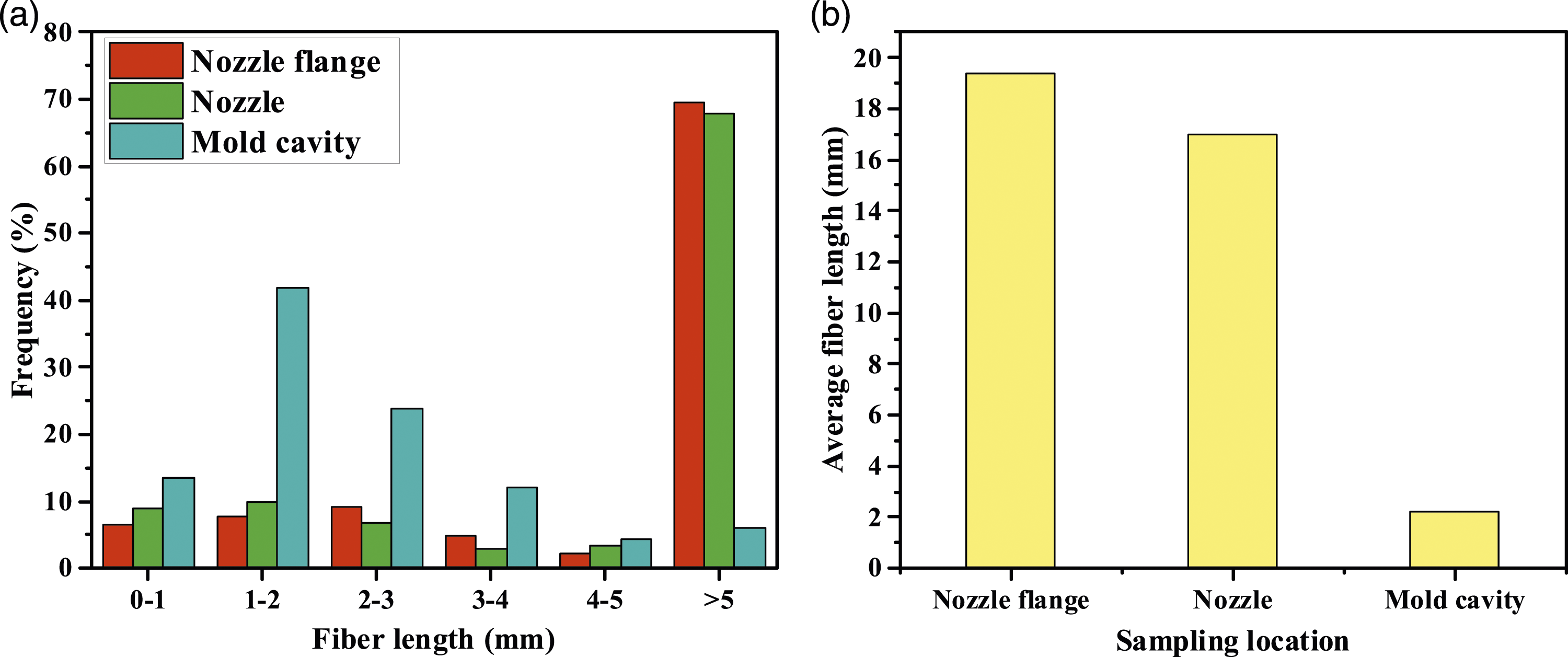
Analysis of POLYFLOW simulation results
Figure 8 shows the flow channel shear stress nephogram and the average shear stress with nozzle apertures of 2 mm, 3 mm, 4 mm, and 5 mm. The shear stress of GF/PP melt in the 0–80 mm zone of the nozzle channel gradually increases with the flow of the molten material, with a gradual increase trend, but the trend increases sharply in the 80–90 mm zone of nozzle outlet. At the same position in the nozzle channel, the average shear stress on the molten material decreases with the increase of the nozzle aperture and is 4981 kPa, 4729 kPa, 4288 kPa, and 3595 kPa at the nozzle outlet, respectively. Shear stress of nozzle flow channels. (a) 2 mm aperture nozzle flow channel; (b) 3 mm aperture nozzle flow channel; (c) 4 mm aperture nozzle flow channel; (d) 5 mm aperture nozzle flow channel; (e) Average shear stress of nozzle channel section.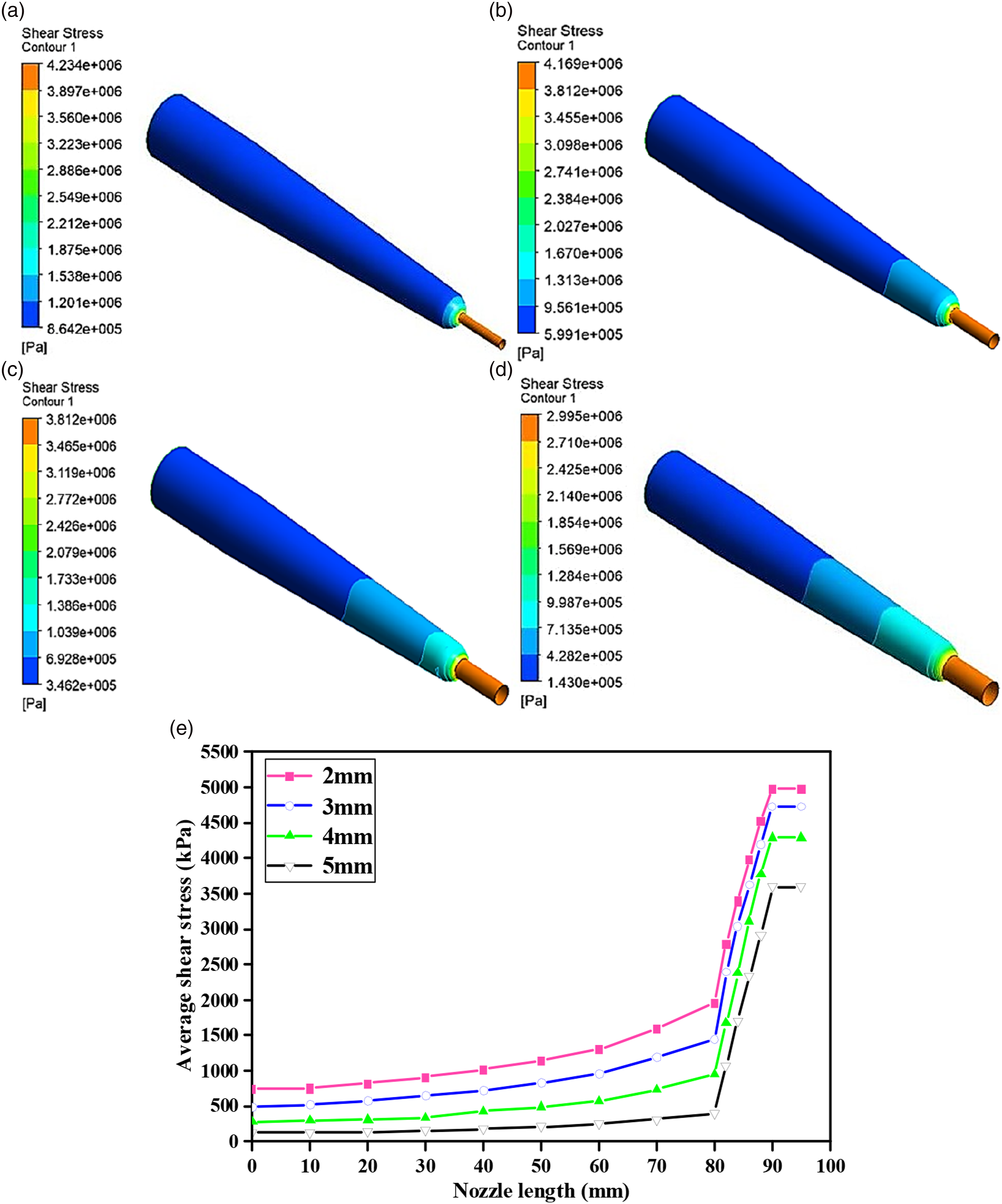
The schematic diagram of nozzles with different apertures is illustrated in Figure 9. The nozzle inlet is connected to the flange, and the inner diameter of the nozzle channel gradually decreases in the 0–80 mm range, causing an increase in the flow rate and resistance on the molten material. This is the reason why the shear stress on the molten material gradually increases as it flows. At the same position of the nozzle channel with different apertures, the flow area of the channel increases with the increase of the nozzle aperture, resulting in a decrease in shear stress, which helps maintain the length of the glass fiber. As for the phenomenon that the shear stress on the melt increases sharply in the 80–90 mm range of nozzle outlet, it is mainly due to the smaller diameter of the nozzle outlet and the sudden change in the flow channel aperture. The smaller diameter of the nozzle outlet can better match the ingate sleeve to establish injection pressure and improve the temperature and homogenization effect of the molten material. This phenomenon also demonstrates that structural changes in the nozzle will exert greater shear stress on the molten material. This is why a straight-through nozzle is chosen in the DFFIM technology to mold GF/PP composites. Schematic diagram of nozzle flow channels with different apertures.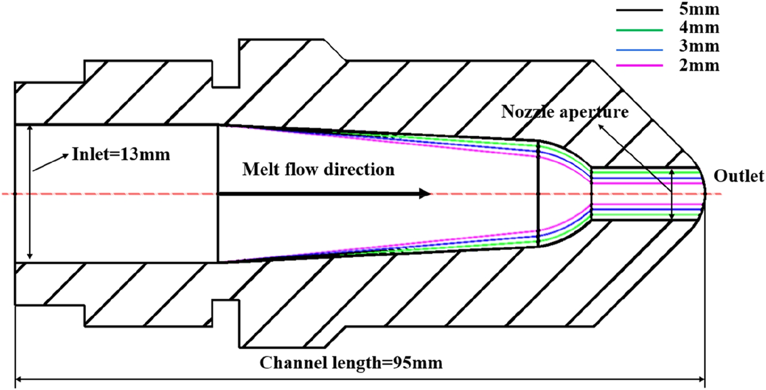
Effect of nozzle aperture on the properties of GF/PP composites
Effect of nozzle aperture on the fiber length
The distribution of the glass fiber length and the average fiber length of GF/PP standard strips with different nozzle apertures is shown in Figure 10. In the 0–1 mm range, the nozzle aperture of 2 mm has the highest proportion of the glass fiber, accounting for 36.73%, which decreases by 23.3% when the nozzle aperture is 5 mm. In the range of fiber lengths larger than 2 mm, the proportion of fiber lengths corresponding to nozzle apertures of 2, 3, 4, and 5 mm is 27.82%, 37.43%, 45.34%, and 46.27% in that order. It can be seen that as the nozzle aperture increases, the proportion of short fibers decreases and the proportion of long fibers increases, with the average fiber length increasing from 1.65 mm for 2 mm aperture to 2.24 mm for 5 mm aperture, an increase of 35.76%. Fiber length of GF/PP composite for different nozzle apertures. (a) Fiber length distribution; (b) Average fiber length.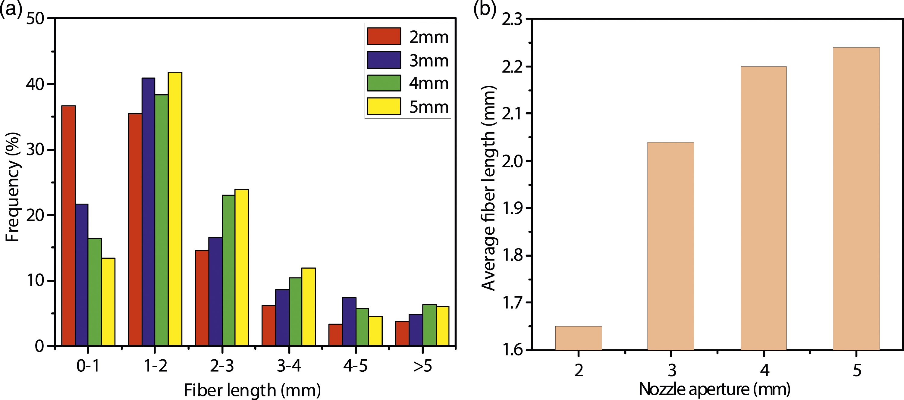
As the nozzle aperture increased, the flow volume of the GF/PP melt per unit time under the same injection pressure increased, which shortened the time for the fiber to be sheared in the nozzle flow channel. Moreover, the increased flow channel area reduced the resistance of the melt, which is more conducive to the alignment orientation of the fibers along the flow direction, reduced the proportion of fibers in the transverse bending state, thus reducing the interaction between fibers and the shear stress on fibers, improving the fiber breakage phenomenon, and increasing the average glass fiber length. When the composite is subjected to external forces, the longer fiber can absorb more energy when it breaks and pulls out from the matrix, while the short fiber may be separated from the resin matrix before the fiber breakage and fail to effectively act as the reinforcement. Therefore, within a certain length range, the mechanical properties of the composites increase with the increase of the fiber length.
Microscopic morphology analysis
Figure 11 shows the SEM microstructure of the GF/PP composites at different nozzle apertures. As shown in Figure A, there is a clear gap between the glass fiber and the PP matrix when the nozzle aperture is 2 mm, while in Figures. B, C, and D, that is, when the nozzle apertures are 3, 4, and 5 mm, there is no obvious gap between the glass fiber and the PP matrix, indicating that the interfacial bonding properties are pretty good. SEM images of GF/PP composites reveal that the smaller nozzle apertures resulted in a reduction of the interfacial bonding properties between the glass fiber and PP. During the injection process, the GF/PP melt flowing through the nozzle was required to overcome the nozzle resistance. Under the same injection pressure, the smaller the nozzle aperture, the greater the resistance to the melt, and the lower the melt pressure that finally reached the inside of the mold cavity, resulting in less force on the GF/PP melt before cooling and forming, and the poorer the bonding properties between glass fibers and PP. SEM micrographs of GF/PP composite interface for different nozzle apertures. (a) 2 mm aperture nozzle; (b) 3 mm aperture nozzle; (c) 4 mm aperture nozzle; (d) 5 mm aperture nozzle.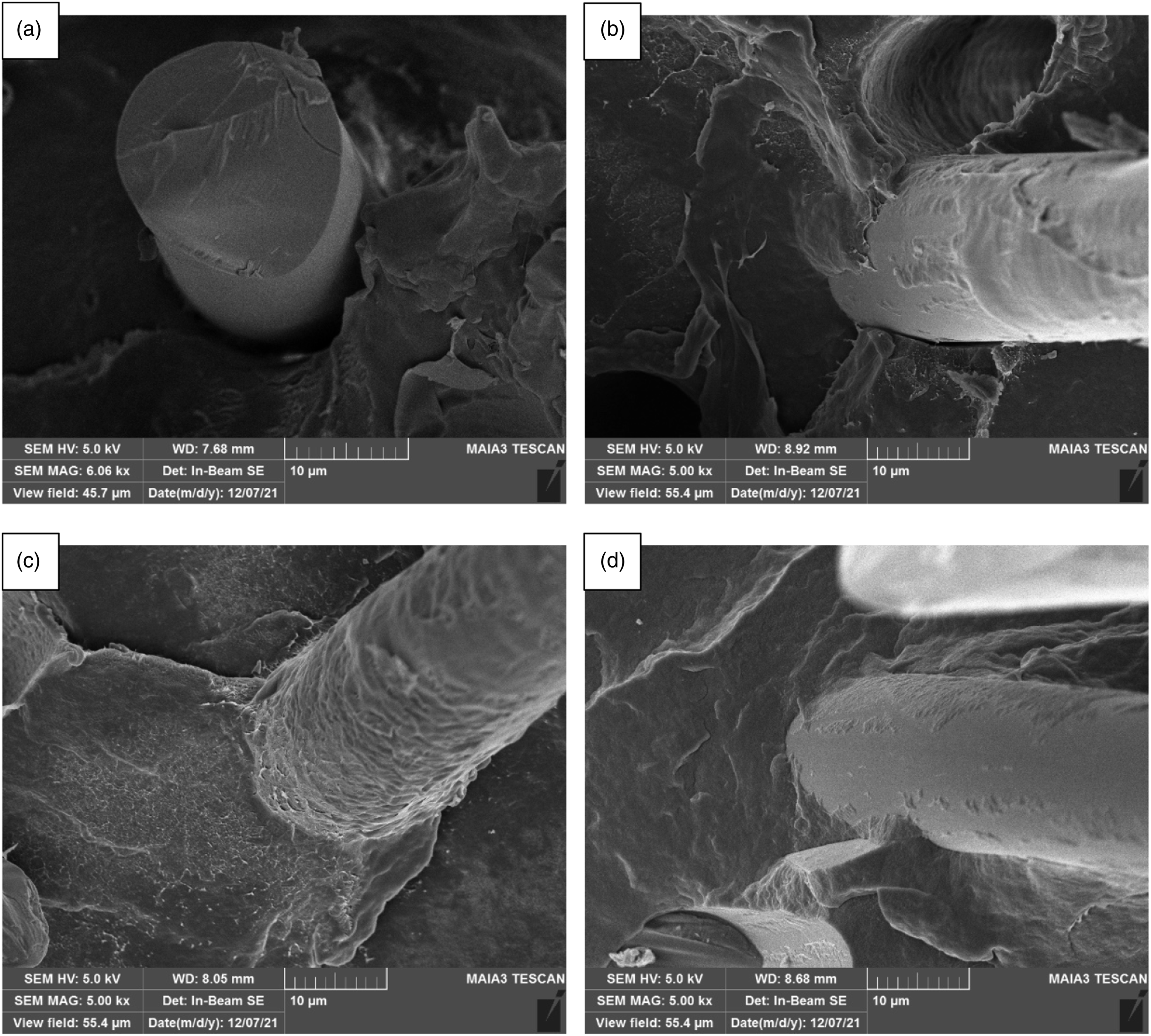
Effect of nozzle aperture on the mechanical properties of GF/PP composites
The tensile, bending, and unnotched impact strengths of GF/PP composites at different nozzle apertures are shown in Figure 12. As the nozzle aperture increases from 2 mm to 5 mm, the bending strength gradually increases from 121.01 MPa to 133.90 MPa, with an increase of 10.66%. The tensile strength generally tends to increase, from 83.70 MPa to 94.95 MPa, with an increase of 13.44%, while the strength change is small between nozzle apertures of 3 mm to 4 mm, only 0.25 MPa. The unnotched impact strength increases from 46.78 kJ/m2 to 61.65 kJ/m2, with an increase of 31.88%. Increasing the nozzle aperture could reduce the shear effect on fibers, resulting in a reduction in fiber breakage phenomenon. Moreover, the increased nozzle aperture reduced the flow resistance of the melt flowing through the nozzle. Under the same injection pressure conditions, the melt pressure was larger when the composite material reached the mold cavity, and the interfacial bonding properties between the fiber and matrix were better. The mechanical properties of GF/PP composites improved with the increase of the effective fiber length and the interfacial bonding properties. As for the anomaly that the tensile strength of the composites increased when the nozzle aperture decreased from 4 mm to 3 mm, this was because the viscosity of the resin matrix decreased with the increase of the shear stress, and the glass fibers were better protected by the resin melt coating. However, the increase in shear action has a more significant effect on fiber breakage, so the tensile properties of the composite show a gradual increase trend with the increase of nozzle aperture. Mechanical properties of GF/PP composites for different nozzle apertures.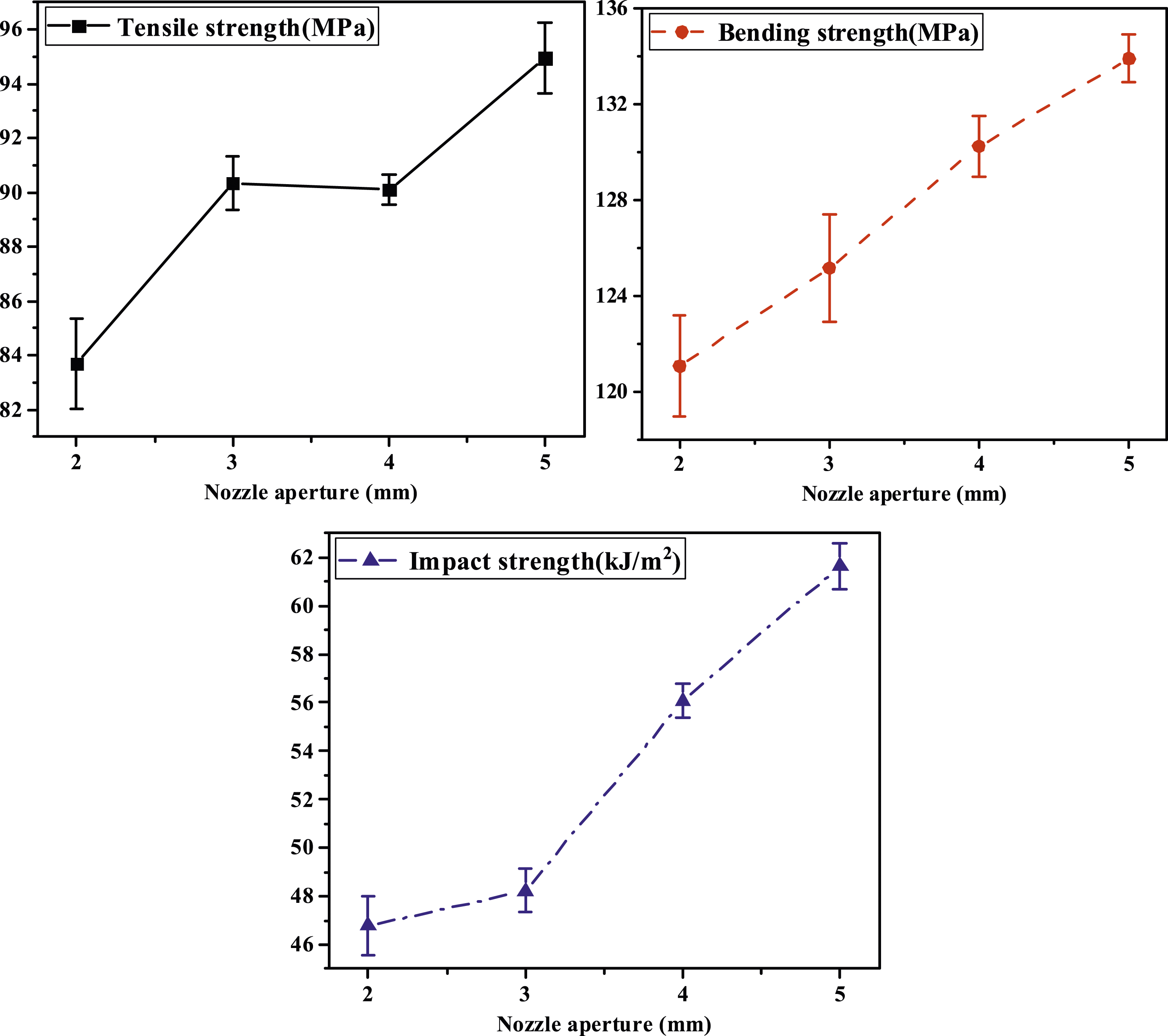
Conclusions
GF/PP composites were fabricated by DFFIM with a specially designed plasticizing unit. By comparing the glass fiber length of GF/PP composites in three different positions of nozzle flange, nozzle outlet, and mold cavity, it was found that the fiber breakage phenomenon was aggravated by the melt through the nozzle, resulting in the reduction of glass fiber length, therefore, the shear stress of nozzle flow channel with different apertures was simulated and analyzed, and the effect of nozzle aperture on the properties of GF/PP composites fabricated by DFFIM was further studied.
The simulation results of POLYFLOW on the nozzle flow channel with different apertures show that the shear stress on the melt gradually increases with the melt flow, which is caused by the gradual decrease of the nozzle runner diameter, and the shear stress increases sharply in the zone where the nozzle outlet aperture suddenly decreases. Increasing the nozzle aperture can reduce the shear stress on the melt, which helps to maintain the residual fiber length and thus ensures the mechanical properties of the composite. From the DFFIM experiment, it can be concluded that the fiber length, interfacial bonding properties, and mechanical properties of GF/PP composites increase with the increase of nozzle aperture, which is consistent with the simulation results. This is because under the same injection pressure, as the nozzle aperture increases, the resistance of the melt decreases, the fibers tend to be aligned along the flow direction, the time and shear stress on the melt are reduced, and the melt pressure when reaching the cavity is greater, so the residual effective length of the glass fiber and the interfacial bonding properties between the glass fiber and PP are enhanced.
Footnotes
Acknowledgements
We would like to thank the Analysis and Testing Center of Beijing University of Chemical Technology for technical support in testing and Guangdong Lijin Plastic Machinery Intelligent Manufacturing Co., Ltd for equipment support.
Declaration of conflicting interests
The author(s) declared no potential conflicts of interest with respect to the research, authorship, and/or publication of this article.
Funding
The author(s) received no financial support for the research, authorship, and/or publication of this article.
Data Availability Statement
The data during the study are available from the corresponding author on reasonable request.