
Abstract
Deployable space structures made from thin-ply high-strain composite (HSC) laminates can be compactly stowed, but prolonged stowage under high curvature can alter their deployed shape due to relaxation. In this research, a dynamic mechanical analyzer-based column bending test (CBT) method, with a custom-developed fixture was used to characterize the relaxation behavior of thin-ply HSCs. Four laminate configurations were prepared from thin-ply unidirectional IM7/PMT-F7 and Astroquartz/PMT-F7 prepregs: (i) IM7/PMT-F7 [0°], (ii) Astroquartz/PMT-F7 [±45°], (iii) Flexlam [±45°/0°/±45°] and (iv) Flexlam [±45°/90°/±45°]. Surface strains of 0.5, 1.0, 1.5, and 2.0% were sequentially applied to the specimen for 100-min durations, each separated by a 1000-min recovery period. This stepped strain approach was performed at 30°C, 50°C, and 70°C. The relaxation results indicate that the fiber-dominated test configuration, UD IM7/PMT-F7 [0°] lamina, shows no measurable relaxation. However, the matrix-dominated configurations, Astroquartz/PMT-F7 [±45°] lamina and the Flexlam laminates, show measurable relaxation. The Flexlam laminates show less relaxation than the Astroquartz/PMT-F7 [±45°] lamina due to the inclusion of unidirectional IM7 carbon fiber. The result also indicates that the relaxation behavior is time and strain-dependent, not temperature-dependent.
Keywords
Introduction
In recent years, thin-ply high-strain composites (HSCs) have gained much attention in deployable space structure (DSS) applications due to the inherent light weight and high stiffness, high operational flexural strain, and low coefficient of thermal expansion. 1 Thin-ply HSC laminates fabricated from thermoset resins and reinforcing fibers are broadly defined as those with ply thicknesses of ∼20–60 μm, compared to standard ply thicknesses of ∼125 μm. 2 Thin-ply HSC laminates are designed to achieve more than 1% flexural strain through multi-scale structural deformation mechanisms.3,4 The small thickness and high operational flexural strain of thin-ply HSC laminate allow cured structural configurations to be flattened and rolled for compact stowage.
In DSS applications, thin-ply HSC laminates are stowed in small volume compartments for extended periods of time prior to being deployed to the operational configuration. The stowage can result in strains approaching 2%, yet once deployed, these thin-walled DSS demonstrate high stiffness and low weight.
1
Examples of the DSS made from thin-ply HSC laminates include but are not limited to, deployable composite booms,
5
tape spring trusses,
6
deployable solar arrays, and spring back reflectors.
7
However, when stowed in a compact configuration under high strain for periods of 1–2 years, the thin-ply HSC laminates show quasi-viscoelastic behavior.
8
Over time, with the fully cured laminates rolled, relaxation occurs due to the quasi-viscoelastic nature. This relaxation leads to incomplete recovery of the shape after deployment
9
and, in extreme cases, leads to impeded deployment due to the stored strain energy dissipation through laminate relaxation.
10
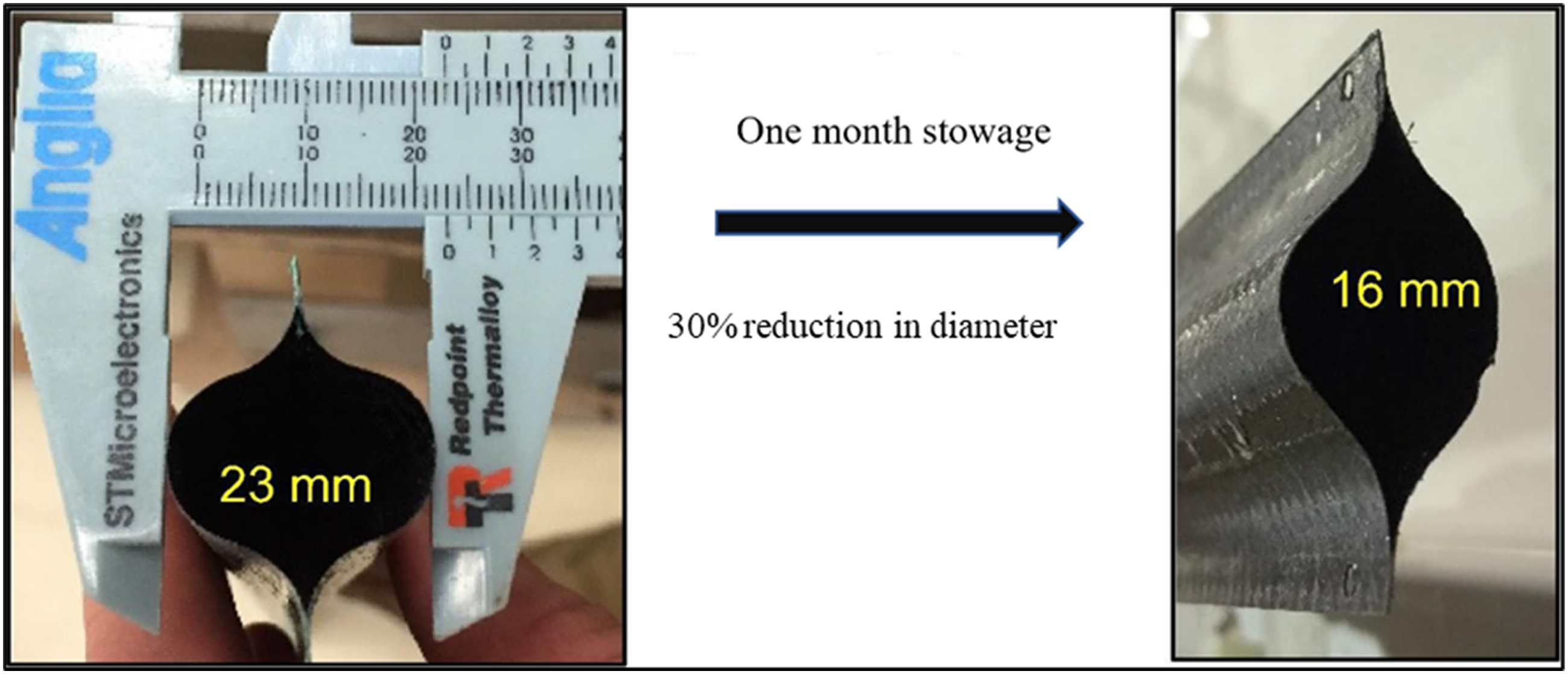
An example of the incomplete shape recovery of a DSS is shown in Figure 1. The deployable boom segment was manufactured from thin-ply HSC laminates. Then, it was flattened and rolled for stowage in a compact configuration for 1 month. The study found that, upon deployment, the boom did not fully recover to the original, as-molded, shape.12,13 Recent studies have shown that the incomplete recovery of DSS shape primarily originates from the relaxation of the thermoset polymer matrix due to the prolonged stowage period under high strains.12,14,15 Thus, it is crucial to understand the relaxation behavior of constituent matrix materials of thin-ply HSC laminates used in DSS to be able to adequately predict the relationship between the stowage time and the resulting degree of shape recovery.
16
Deformation of a composite boom after prolonged stowage due to the relaxation.
11
Previous studies have investigated the stress relaxation and recovery behavior of several neat resins used to manufacture thin-ply HSC at various test conditions ranging from low to high strains and temperatures. The results indicate that independent of resin type, each resin shows stress relaxation and incomplete recovery.12,14,15 Thus, since the relaxation of thin-ply HSC laminates is primarily dependent on the neat resin, the orientation of the reinforcing fibers is expected to significantly affect the degree of stress relaxation.
For predictive engineering purposes, one would ideally test the HSC laminates at relevant temperatures and strains, and then use the data in models incorporating time-dependency to predict the dimensional stability of the DSS structure. However, there is a limited body of research focusing on the direct relaxation and recovery behavior of thin-ply High Strain Composite (HSC) laminates under realistic loading and boundary conditions involving significant deformation. Traditional testing methods prove inadequate in handling substantial configuration changes induced by elastic deformations prior to failure. A previous study employed a large displacement buckling test to assess the bending behavior of thin-ply composites, reaching a maximum strain of 2.8%.17,18 While the Large Deformation Four Point Bending Test offers an alternative capable of high curvatures, it is prone to premature failure due to stress state transitions. 19 Furthermore, a recently reported platen test designed for assessing thin composite laminates presents challenges with non-uniform moment distribution. 20
Stress relaxation and recovery behavior of thin-ply HSC laminates have been investigated using CBT, but the technique utilized was limited to less than 1.0% strain, well below the maximum operating strains seen in HSC laminate applications. 11 Thin-ply HSC laminates can experience bending strains up to, and sometimes exceeding, 2%.1,21 The relaxation and recovery behavior of thin-ply HSC laminates at these strains and various temperatures are expected to be distinct from results at low strain due to the nonlinear time-dependent response of the matrix polymer. In addition, fiber orientation affects the relaxation and recovery behavior of HSC laminates. Thus, to develop predictive capabilities that accurately capture the relaxation and incomplete recovery related to long-term stowage of a DSS, an understanding of the complex time-temperature-strain dependence of thin-ply HSC laminates is required. Only limited research has been presented on the understanding of relaxation and recovery of HSC laminates at high strain and temperature that genuinely represent the conditions that thin-ply HSC laminates undergo during the life cycle of DSS. Thus, an experimental approach that can be used to directly measure the relaxation and recovery response of thin-ply HSC laminates at relevant strain and temperature is needed.
Recent research has described the Column Bending Test (CBT) method as an approach to experimentally characterize the relaxation and recovery by applying large deformation bending to thin-ply HSC materials. 18 This test method uses a mechanical test frame to apply an axial compressive load, introducing curvature, and thus a strain, into thin-ply specimens. However, the conventional mechanical test frame used for the CBT has limited control over the targeted strain because the strains are predicted based on the applied load and curvature from Digital Image Correlation (DIC) measurements. Additionally, due to only moderate levels of sensitivity to applied load, conventional test frames require thicker laminates than the actual thickness of the HSC laminates used in DSS.11,22 The current study focuses on developing a technique capable of directly measuring and aiding in the understanding of the relaxation and recovery behavior of thin-ply HSC laminates, consistent with thicknesses being applied in DSS, at controlled temperatures and high strains.
Fundamentals of DMA-based CBT
To introduce high flexural strain, the CBT test, which enables >1% to be introduced into thin composite laminates, was developed.
18
This unique test has been used by several researchers in the field of high-strain composites but has not yet become an ASTM-recognized standardized test.9,18,22,23 While the CBT test geometry has been employed using tensile test machine in a considerable number of papers, it is noteworthy that all prior studies utilized larger samples, which tend to be thicker than that which is usually used in fabricating DSS.8,9,18,23,24 The current work introduces a significant modification to the test protocol by scaling down both the specimen and fixture. The completed CBT fixture, attached to the DMA, with a thin-ply unidirectional (UD) carbon fiber composite specimen clamped in position, is shown in Figure 2. This reduction in test size enables the performance of the CBT test within a DMA, facilitating a more comprehensive investigation of the viscoelastic response of individual thin plies and corresponding laminates. A UD IM7/PMT-F7 [0°] specimen fully fixtured in DMS 6100.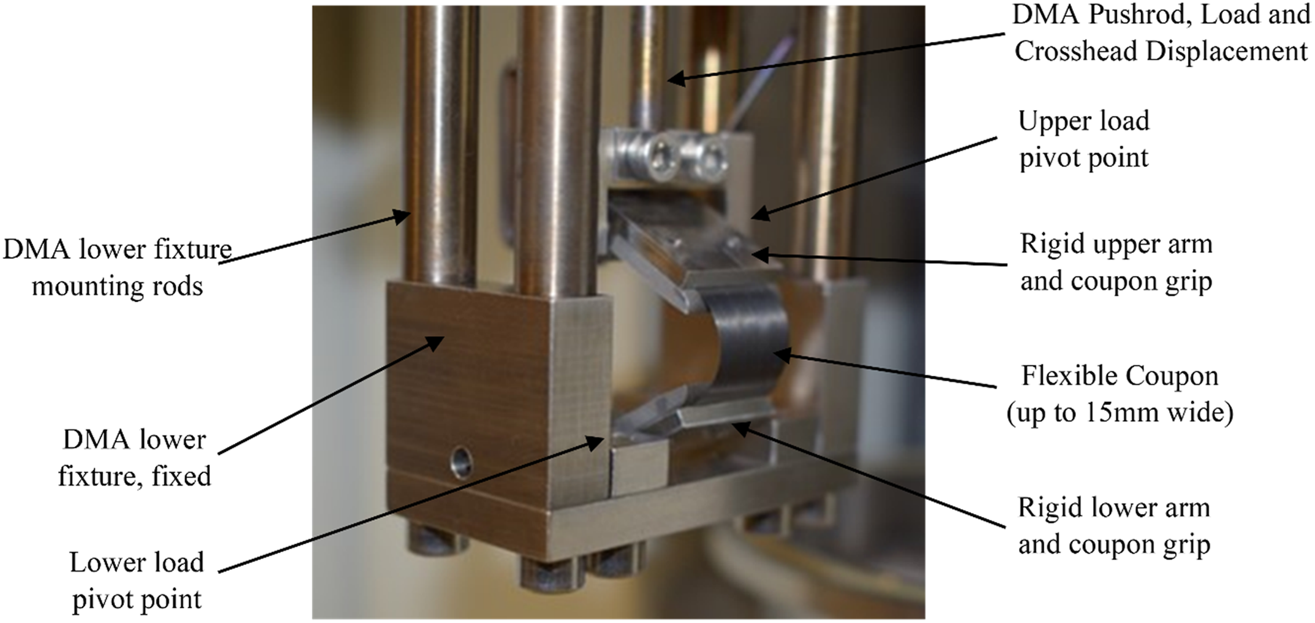
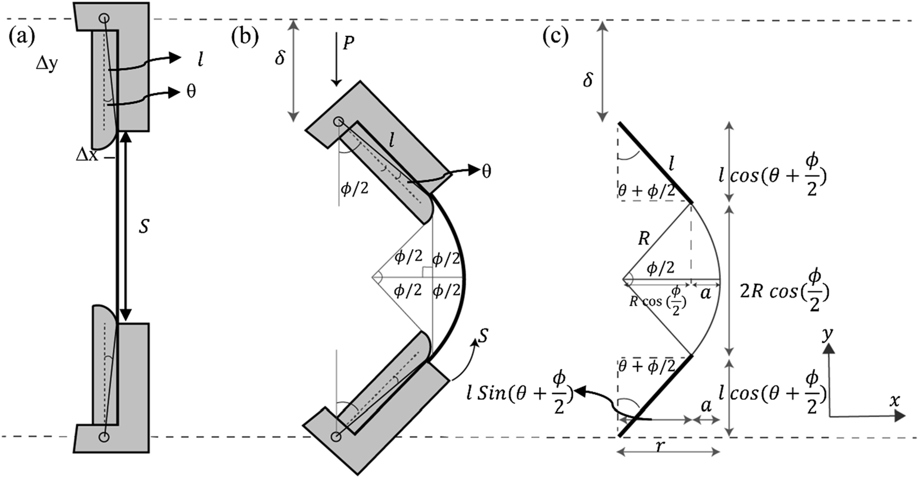
Based on the assumptions that curvature is constant over the arc length of the bend specimen, the closed-form relationships known as CBT equations, for the maximum and minimum bending moments and curvature were derived from the vertical displacements and applied loads.
18
A free-body diagram of the DMA scale CBT fixture is shown in Figure 3 where Free body diagram of the DMA scale CBT fixture (a) initial test geometry, (b) test geometry after applying vertical displacement, and (c) generalized form of the test geometry.
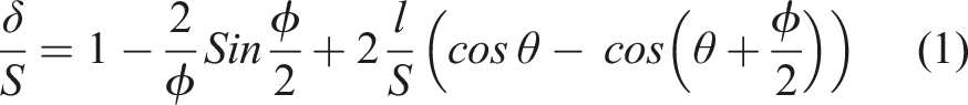
The application of vertical displacement as a ratio to the gage length is described by equation (1)
18
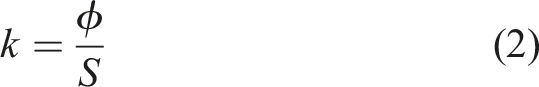
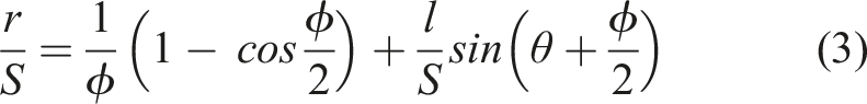
The effective moment arm length,
The maximum moment, which occurs at the midspan and the tension face of the specimen, is given by equation (4)
18

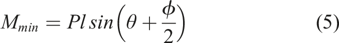
The minimum moment, which occurs at the compression face and at the ends of the specimen is given by equation (5)
18
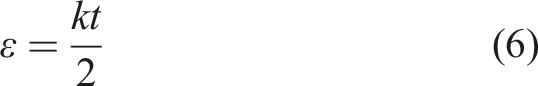
Finally, the outer surface strain can be determined from equation (6)
18
In the current effort, relating the DMA-introduced axial displacement to the resultant flexural strain in the test coupon is fundamental to the stepped strain extended recovery approach using the CBT fixture.
Time dependency of thin-ply HSC
The time and temperature-dependent mechanical behavior of thin-ply HSC laminates appear from the inherent time-dependent behavior of the polymer matrix and depends on the stacking sequence, fiber orientation, and the direction of loading.
25
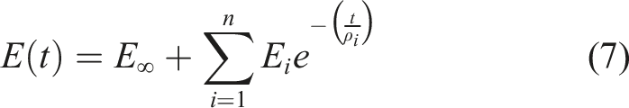
The theory of linear viscoelasticity is used to describe the time and temperature dependence of the mechanical behavior of viscoelastic polymers. The constitutive equation for linear viscoelastic materials, in terms of relaxation modulus under isothermal conditions, can be written in Prony series form as
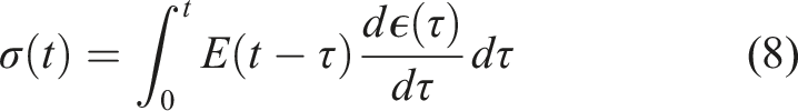
The stress-strain constitutive relation for uniaxial deformation can be expressed in the form of the Boltzmann superposition principle integral as
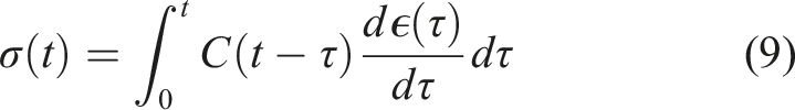
However, thin-ply HSC materials are anisotropic, meaning that deformation occurs in three dimensions at varying rates. For an anisotropic viscoelastic material, the constitutive equation in a linear viscoelastic regime can be written in the Prony series form as
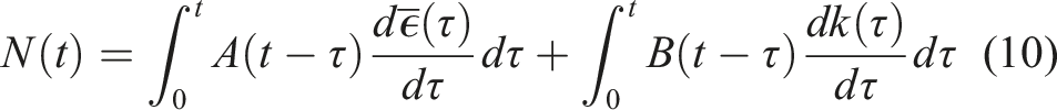
The viscoelastic relationship of thin-ply HSC materials can be more easily described by using the Kirchhoff plate theory due to the small thickness of the HSC laminates. By invoking the Kirchhoff assumptions, the integral formulation can be reduced to the plate formulation for a laminate as
The ABD matrix, referred to as the relaxation matrix, can be determined from the CBT data and expressed in the Prony series as
9
The shift function is defined as the ratio between relaxation times at temperature, T, and the reference temperature. The shift factor is often approximated using the time-temperature superposition principle, and the Williams–Landel–Fery or Arrhenius equation based on the assumption that the thin-ply HSC laminates are thermorheologically simple.9,12,25
Experimental method
Materials
The response of a thin-ply HSC laminate called Flexlam, initially pioneered by T. W. Murphey at the Air Force Research Laboratory was the focus of this research.29,30 This laminate is composed of a single-ply of UD IM7 carbon PMT-F7 prepreg oriented at 0°, sandwiched between two plies of Astroquartz plain weave (PW) PMT-F7 resin prepreg oriented at 45°, resulting a laminate stacking sequence of [±45°Astroquartz PW/0°IM7/±45°Astroquartz PW]. The incorporation of the Astroquartz, rather than, for instance, a thin biaxial carbon fiber ply, enables higher strains, which are critical to achieving the tightest packaging of the boom. The lower strain allowable for the carbon fibers, especially in compression, limits the radius of curvature that an all-carbon fiber tape spring can be coiled and stowed. While using an all-carbon fiber tape spring could increase the stiffness of the boom, the tradeoff in packaging volume is not considered acceptable. Thus, the use of the biaxial Astroquartz helps stabilize the central carbon fiber ply used to generate the deployment force, while enabling significantly greater strains and the associated reduced packaging volumes.
Thin-ply HSC lamina and laminate properties.
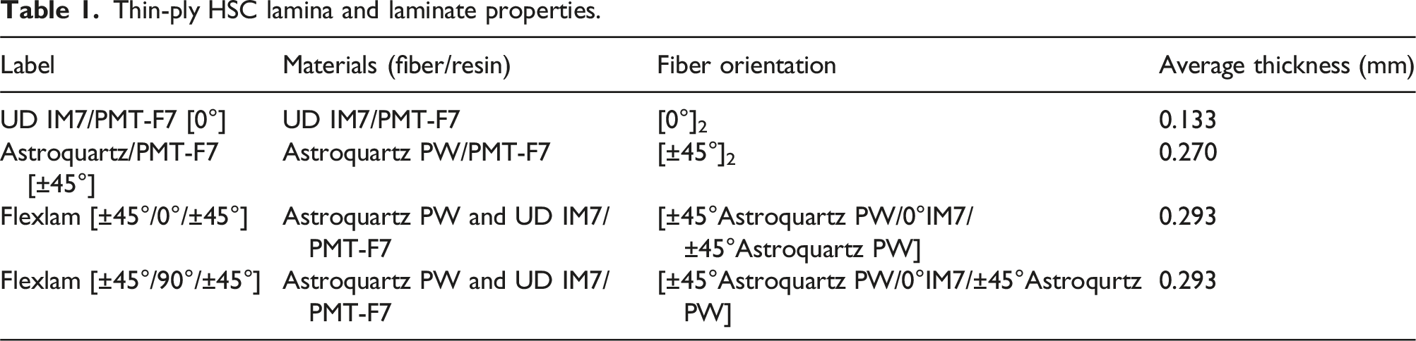
The Flexlam laminates were cut into specimens that allowed testing as both [±45°/0°/±45°] and [±45°/90°/±45°] laminates. These two orientations represent the longitudinal direction in which a Flexlam-based tape spring is rolled and the transverse direction in which it is flattened. The [±45°/0°/±45°] test direction provides viscoelastic information related to the rolling of the tape spring and the [±45°/90°/±45°] test direction provides information related to the lateral curling/flattening which occurs during stowage, both of which can affect the deployed shape.
Specimen preparation
The Seiko DMS 6100 DMA has a force application limit of 9.8 N and can provide a maximum vertical travel of 20 mm. Based on these limitations of the DMS 6100, test specimens of the desired thickness of 0.133 mm, 0.270 mm, and 0.290 mm were prepared for the UD IM7/PMT-F7 [0°], the Astroquartz/PMT-F7 [±45°] and the Flexlam laminates, respectively. These thicknesses allowed the application of the desired strain for the planned experiments while keeping the resulting required displacements and loads within the DMA capacity. The thickness of the UD specimen was intentionally reduced to maintain the fixture arm rotation (Φ) within 160° while still achieving the targeted strain and remaining within the force limitation of the DMA. The kinematic equations, as presented from Equation 1 to Equation 6 encompass the thickness, and during the processing of the raw data using the CBT kinematic equations, the thickness dependency was accounted for. Consequently, larger gage lengths were necessary for the Astroquartz/PMT-F7 [±45°] and Flexlam laminate to attain the desired curvature and strain in relation to their respective thickness, within the force and displacement limitations of the DMA.
The curing of the three test materials was performed according to the manufacturer’s cure cycle. All the materials were cured according to the same methods utilized for the neat resin in the previous work. 15 The materials were cured as a large laminate so that the CBT test coupons could be sectioned from the single bulk sheet.
UD IM7/PMT-F7 [0°] laminates were cut into CBT specimens of 14–15 mm in width and 25–30 mm in length and Astroquartz/PMT-F7 [±45°], Flexlam [±45°/0°/±45°] and Flexlam [±45°/90°/±45°] laminate specimens were cut to the same width and 36.5 mm in length. The edges of the test coupons were polished using 600 and 800-grit sandpaper to remove any damaged material from the edges and reduce the number of flaws in the coupon. An example of the Astroquartz/PMT-F7 [±45°] specimen, ready-to-test, is shown in Figure 4. An Astroquartz/PMT-F7 [±45°] lamina specimen with the tension face (T = Top, B = Bottom).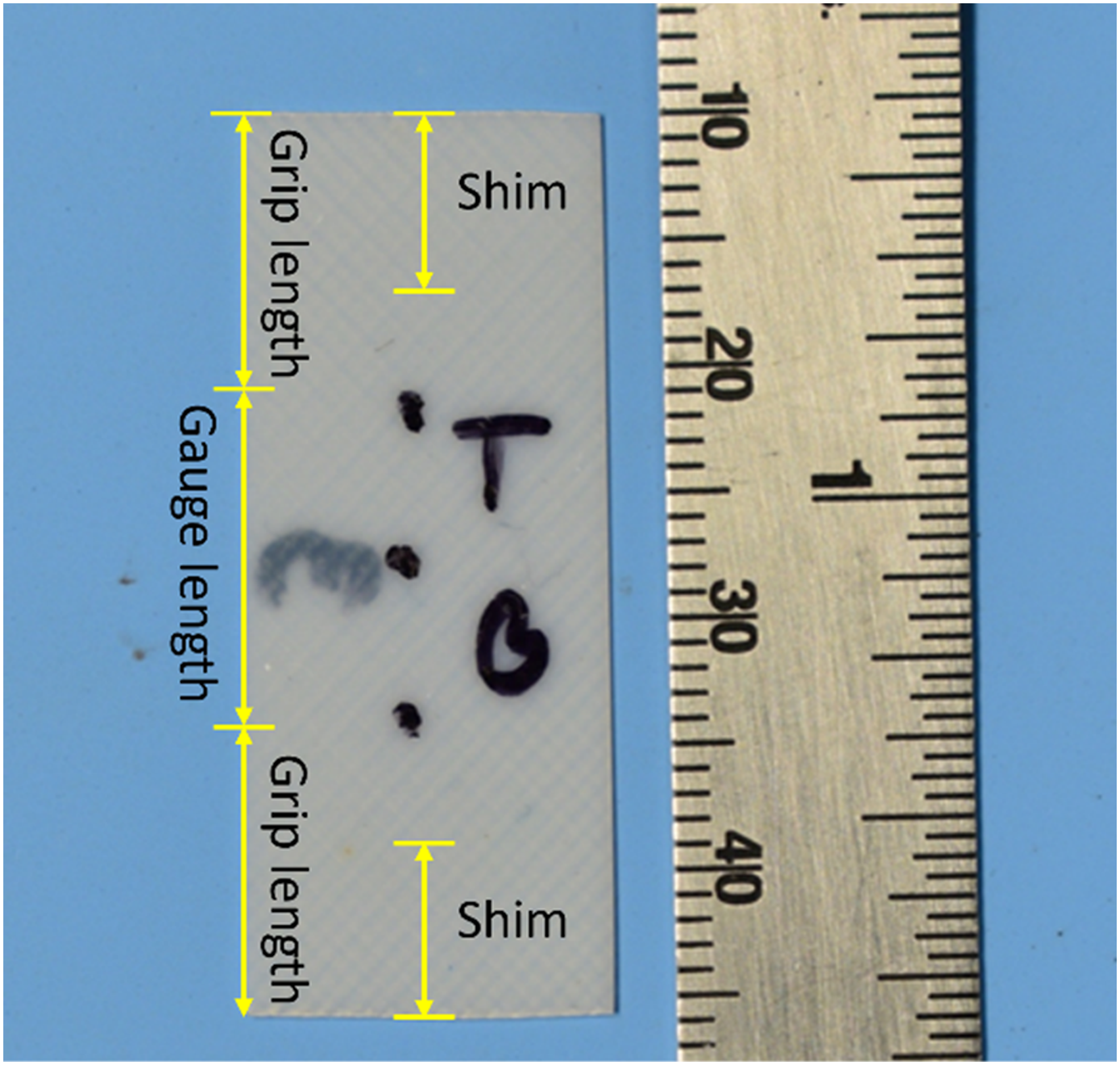
Specimens, stored in a desiccator post-preparation, had moisture levels monitored using wireless humidity sensors. To prevent moisture gain during mounting in the DMA, specimens were immediately transferred. Preliminary trials determined that an 800-min isothermal hold stabilized the moisture content inside the DMA furnace at 1–3%. Once verified, the humidity sensor was removed for most DMA tests.
Column bending test procedure
Taking advantage of the programmability and precision of the displacement, load, and temperature control in the DMA, a loading profile was developed, which steps a single specimen through four sequential periods of strain-induced relaxation, followed by recovery, as presented in Figure 5. This Stepped Strain Extended Recovery (SSER) approach is applied under isothermal conditions. The application of the SSER approach in the DMA has been previously described for the neat thermoset polymer matrix materials under tensile loading conditions.
15
For this study, the (SSER) approach is applied in bending to the thin-ply HSC laminates. Schematic representation of the four sequential strains applied during the SSER program in the DMA to a single specimen.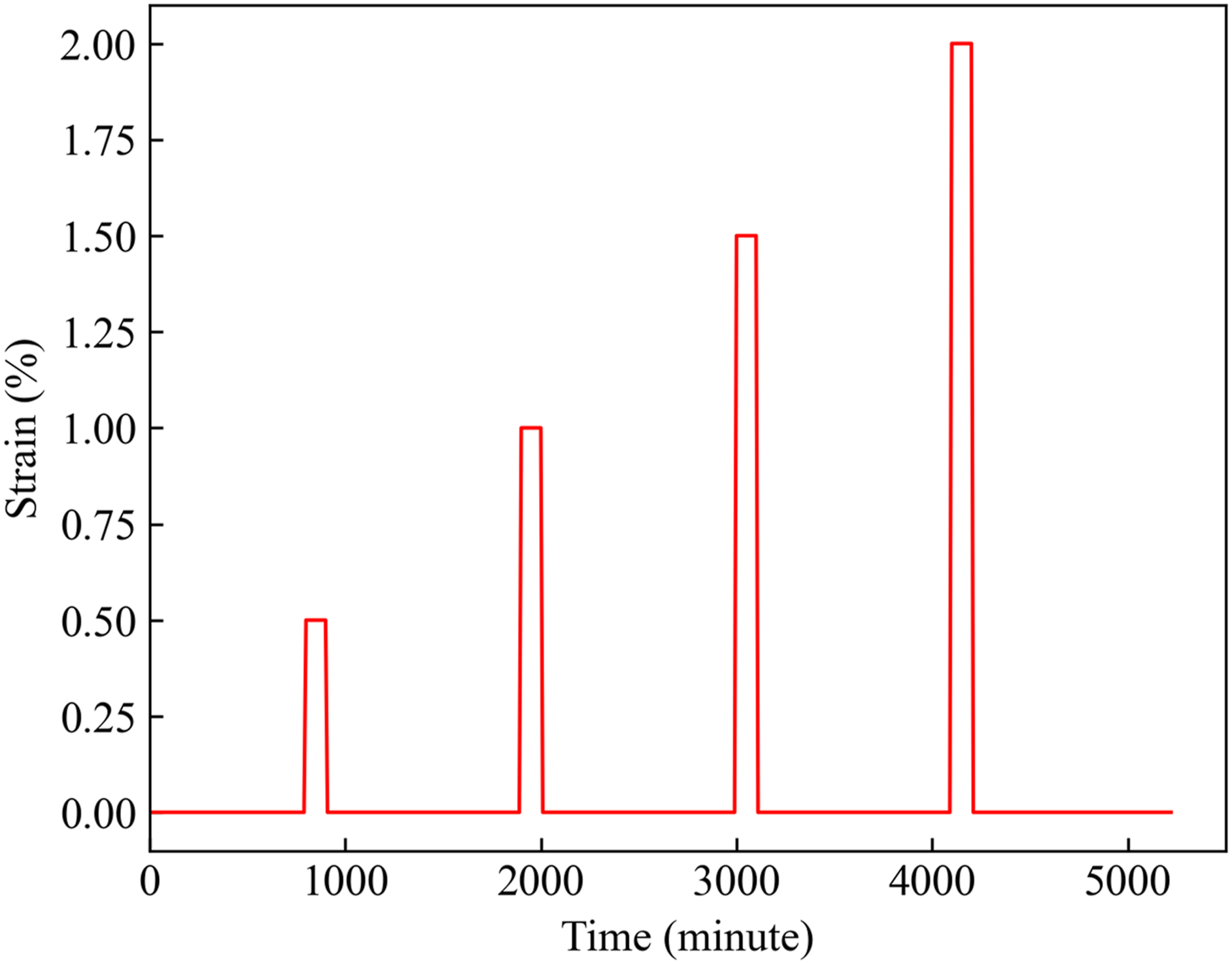
Special care was taken to attach and align the specimen in the custom CBT fixture clamp made for the DMS6100. An adjustable precision parallel set was used to precisely control the separation of the two clamps and therefore, the gage length. Figure 6 shows the specimen attachment procedure into the CBT fixture clamp. From both grip sections of the specimen, as illustrated in Figure 4, a section of 6.44 mm in length was trimmed, and the trimmed ends were converted into shims, which were also trimmed to allow the clamping screws to pass through. Figure 6(a) shows a shim with two holes sitting on the grip plate. The placing of shims ensures that the thickness would be consistent in each material case, and thus, uniform clamping pressure would result. Once the shim and remainder of the specimen were placed and adjusted, the clamping plate was then positioned and the screws were tightened. Figure 6(b) shows the end of the specimen attached to the CBT fixture grip. The same process was applied to attach the opposite end of the specimen. The shim and cut specimen for the opposite end were placed into the clamping plate, as presented in Figure 6(c) and the opposite clamping plate was placed and secured by tightening the screws. Procedure for attaching specimens to the CBT fixture (a) A 6.44 shim, cut from the grip length, sitting on the CBT fixture grip plate (b) Shim and the cut specimen are attached to the CBT fixture grip (c) Opposite end of the cut specimen and a shim is sitting on the grip plate (d) A ready-to-test specimen attached to both fixture grip.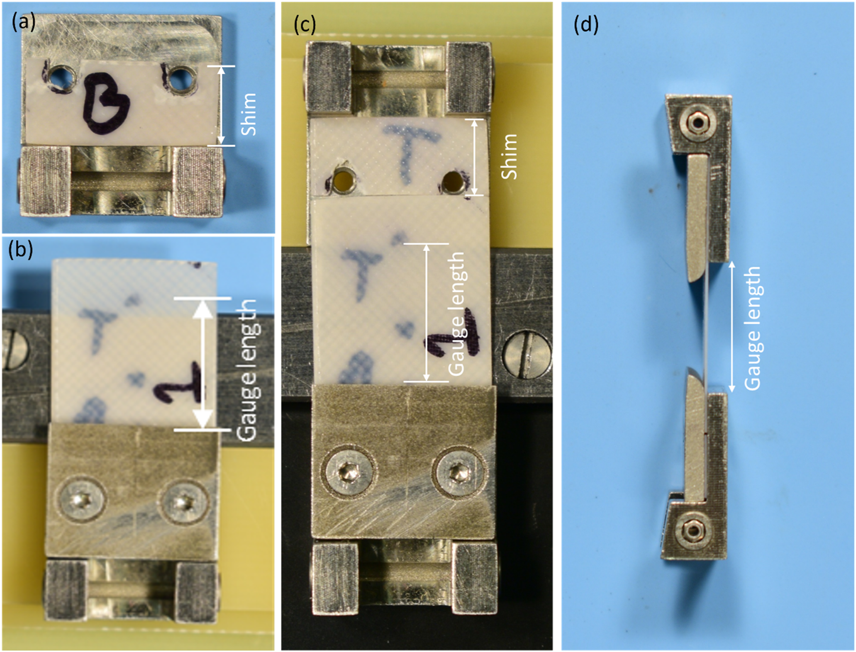
Specimen dimensions and test details.
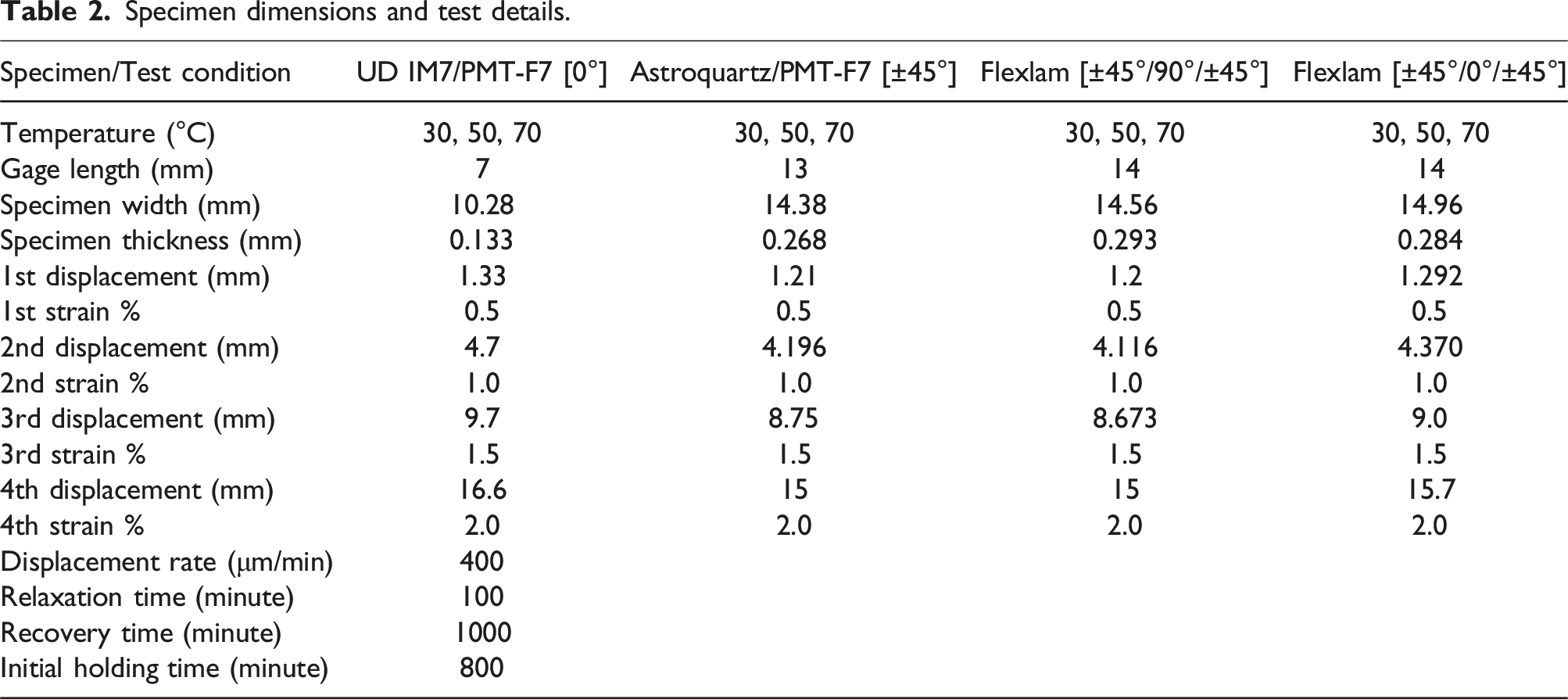
The displacement rate of 400 μm/minute is slow compared to the instantaneous strain typically specified for a stress relaxation experiment. This lower rate is chosen to prevent the early shutdown of the DMA prior to starting the test and prevent the overshoot followed by a rebound back to the target strain caused by the mechanical testing equipment in the stress relaxation experiment.31,32 Even a small amount of overshoot can cause significant errors when estimating the viscoelastic properties of materials. 31
Within the limitations of the DMA maximum load and pushrod displacement, acceptable test specimen dimensions were determined, which allowed the maximum (2.0%) strain to be achieved. The Seiko DMS6100 software limits a programmed displacement-controlled experiment to a maximum pushrod displacement of 5 mm in a single program. Since a total pushrod displacement approaching 20 mm is necessary for 2.0% strain, the 5 mm programmed displacement limitation precludes the incorporation of all four strains in a single program without manual intervention to reset the zero-displacement starting position within the DMA. Thus, three sequential programs were required, with a manual reset between them. This resulted in the programming of the pushrod displacements for the 0.5% and 1.0% strain in a single experiment within a 5 mm displacement, followed by manual intervention and reinitialization of the starting pushrod position for each of the 1.5% and 2.0% strains. During the reinitialization, the specimen, still attached to the clamps, was removed from the DMA chamber and replaced after reinitialization. The next strain step was immediately initiated to avoid any additional recovery in the test specimen.
Processing of the raw data
The data directly collected from the DMA-based CBT for a single run of the SSER method is in the form of the applied displacement versus time and the associated load versus time. The collected raw data were then converted to the average moment per width versus curvature by applying the kinematic equations of CBT geometry. First, the rotation of the fixture arm,
Results and discussion
Raw data collection from DMA-based CBT
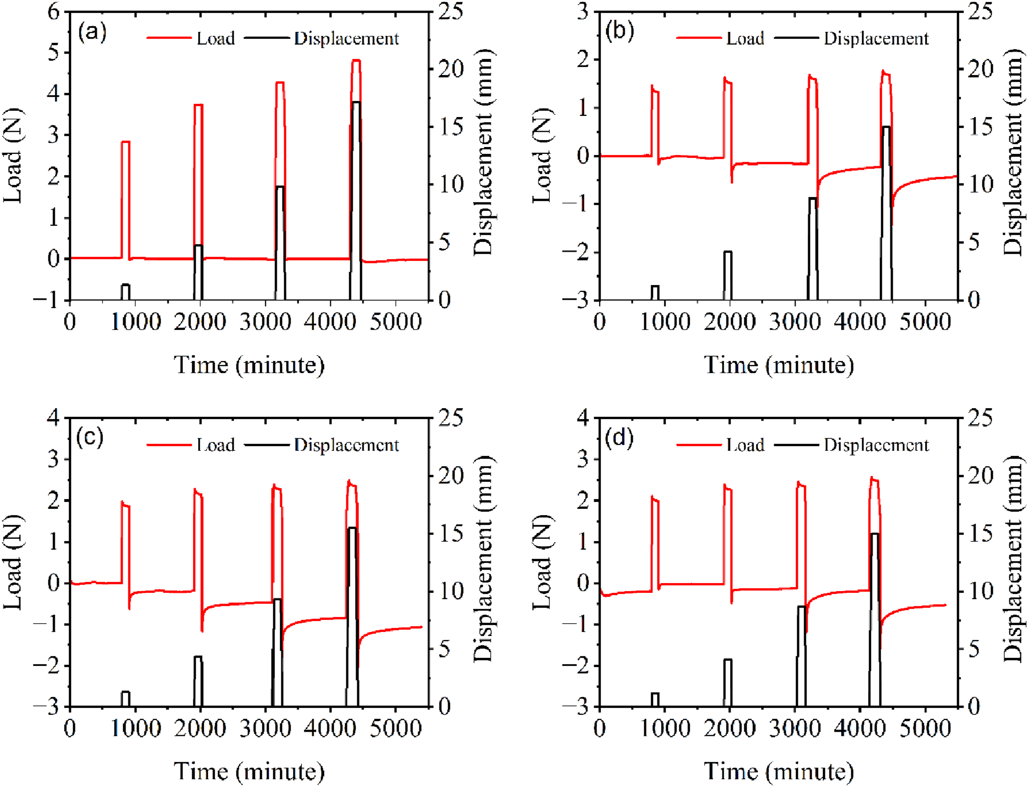
In this study, the test temperatures were restricted to 30°C, 50C and 70°C, as this temperature range was considered typical of long-term stowage prior to launch and was considered most useful for a parallel viscoelastic simulation effort. These temperatures were well below the glass transition temperature of the matrix material. The goal of the effort was to determine information that could be used to better understand the effects of extended-duration stowage on deployment characteristics. The load response during the complete stepped strain profile, corresponding to 0.5%, 1.0%, 1.5%, and 2.0% for UD IM7/PMT-F7 [0°], Astroquartz/PMT-F7 [±45°], Flexlam [±45°/0°/±45°], and Flexlam [±45°/90°/±45°], tested at 30°C, 50°C, and 70°C, are shown in Figure 7–9. Pre-strain periods started from zero load, indicating that the specimen is effectively unloaded. The starting zero loads are controlled within the DMS 6100 software. Load and displacement versus time data at 30°C of (a) UD IM7/PMT-F7 [0°] (b) Astroquartz/PMT-F7 [±45°] (c) Flexlam [±45°/0°/±45°] (d) Flexlam [±45°/90°/±45°]. Load and displacement versus time data at 50°C of (a) UD IM7/PMT-F7 [0°] (b) Astroquartz/PMT-F7 [±45°] (c) Flexlam [±45°/0°/±45°] (d) Flexlam [±45°/90°/±45°]. Load and displacement versus time data at 70°C of (a) UD IM7/PMT-F7 [0°] (b) Astroquartz/PMT-F7 [±45°] (c) Flexlam [±45°/0°/±45°] (d) Flexlam [±45°/90°/±45°].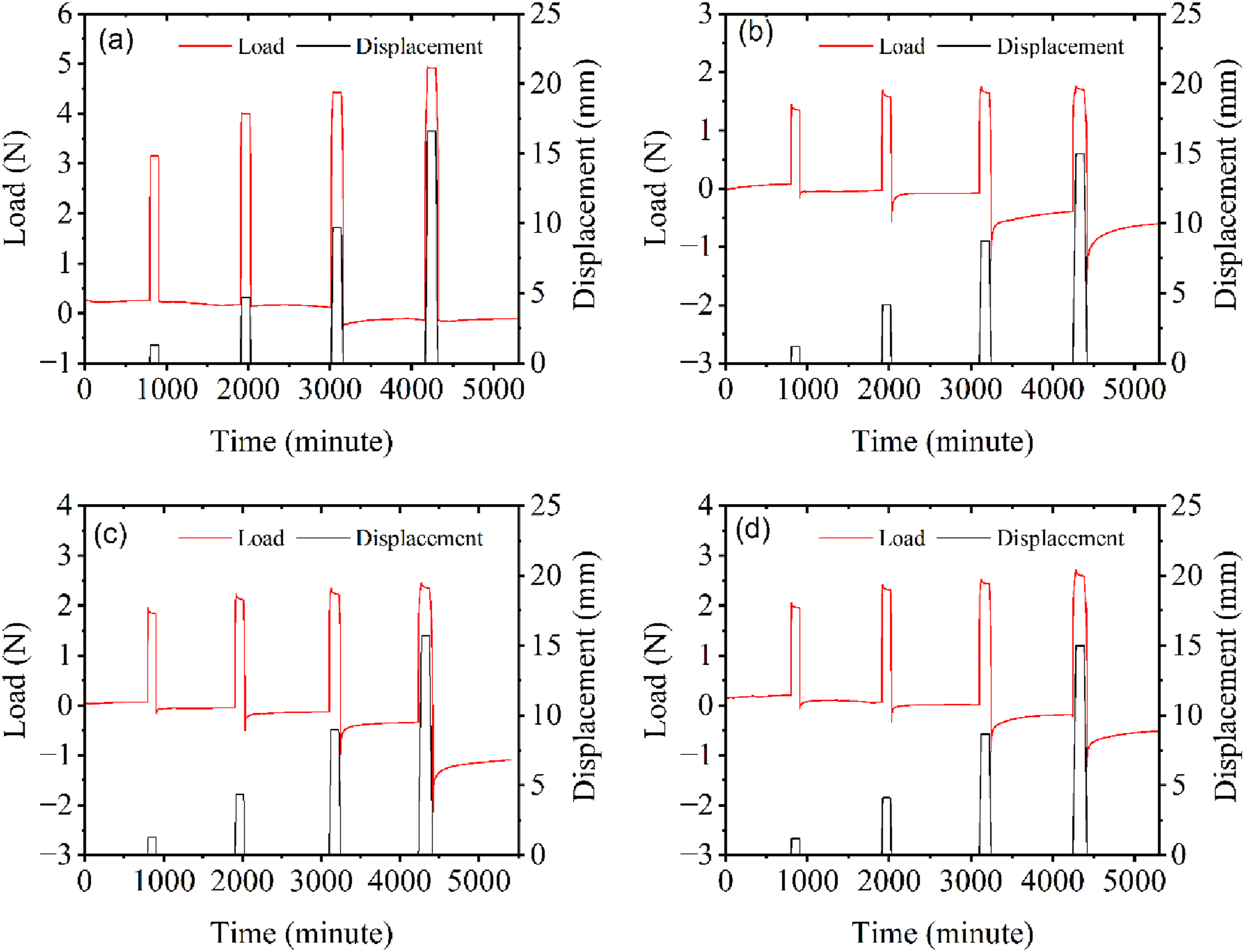
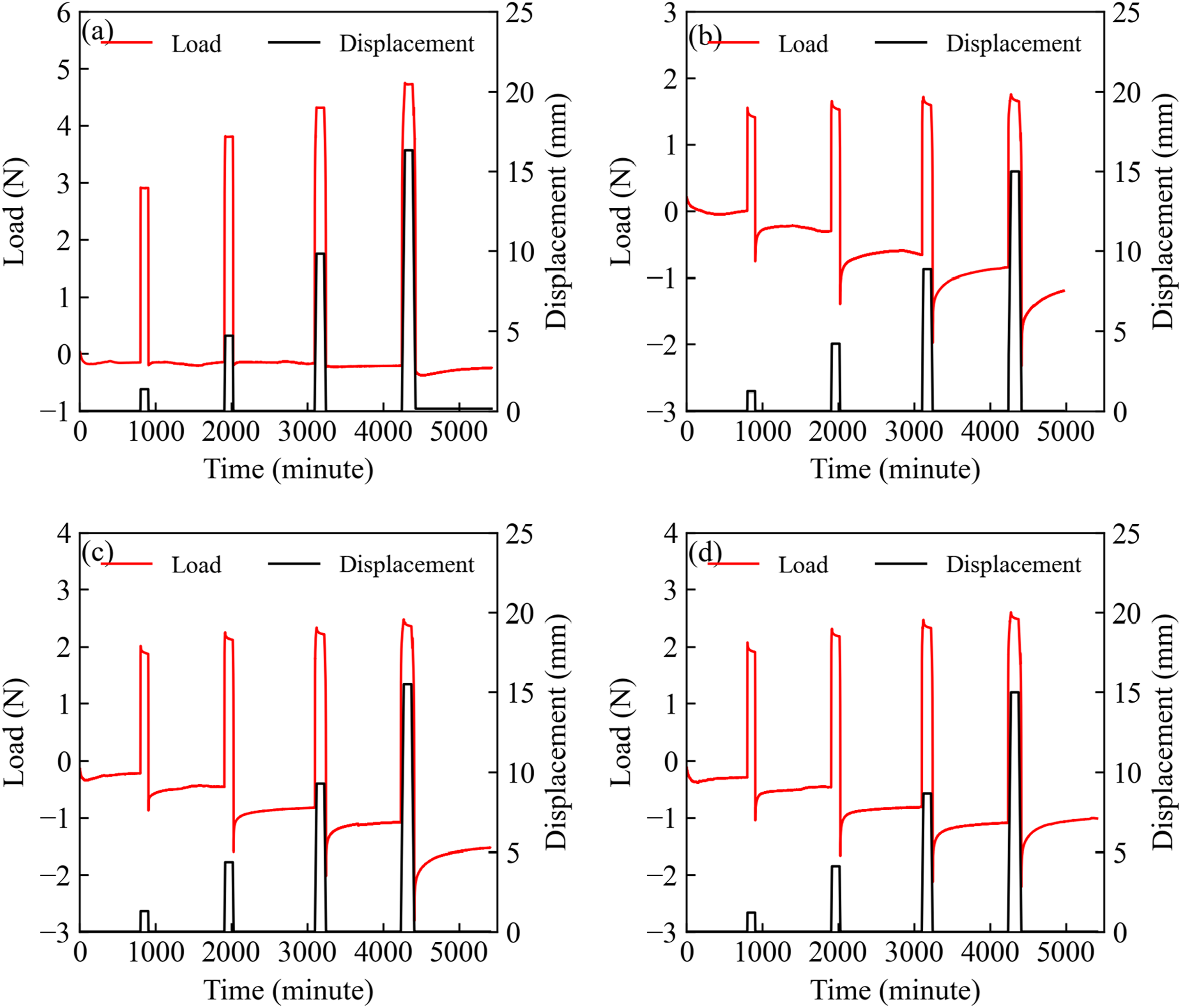
It was expected that any viscoelastic effects would be greatest at the highest temperature, in the range, which is represented by the loading curves. UD IM7/PMT-F7 [0°] laminate is fiber-dominated where the composite laminate behavior is dictated by the fiber suggesting a response similar to that of an elastic material.33,34 As a result, there is no noticeable load drop over the relaxation period, with the exception of an almost imperceptible drop at the largest displacement, consistent with the 2% strain case, as shown in Figure 9(a). This indicates that UD IM7/PMT-F7 [0°] shows no significant relaxation within the test temperature range. Further, when the UD IM7/PMT-F7 [0°] laminate returns to the starting position, initiating the recovery period, the load also returns to the starting value. These results indicate that the fiber-dominated UD IM7/PMT-F7 [0°] behaves effectively in an elastic fashion, showing no notable relaxation and no subsequent recovery at any of the tested strains and temperatures.
For each of the other laminates, the responses at each temperature presented in Figure 7–9, demonstrate a measurable degree of relaxation as indicated by a load drop during the 100-min constant displacement period. Each of these laminates is constructed with [±45°] plies on the outer surface resulting in matrix-dominated flexural stresses during loading. Following the relaxation period at each strain, the displacement is returned to the starting position. As a result, the corresponding load drops into negative values, with the lowest magnitude at the instant of unloading, and slowly increases during the 1000-min recovery period. The elastic after-effect of a linearly viscoelastic material is responsible for dropping the load to lower than the baseline load value once the strain is released.35–37 Usually, for linearly viscoelastic materials in a relaxation experiment, after a relaxation period has been completed and the strain is released, the instantaneous elastic spring-back is followed by a time-dependent decay of the stress.35–37 Upon returning the displacement to zero, after each incrementally higher displacement, the load drops to a lower value than in the previous case for the Astroquartz/PMT-F7 [±45°], the Flexlam [±45°/0°/±45°], and the Flexlam [±45°/90°/±45°] laminate, as shown in the load versus time charts of Figures 7–9. The magnitude of this viscoelastic effect is greatest at the highest strain for each temperature and, ultimately, at the highest test temperature, as seen in Figure 9. This can be related to the concept that the higher the strain, the greater the spring-back force in the viscoelastic elements, which results in stronger elastic after-effects, leading to a greater negative value of the load.35–37 Thus, it is concluded that the recovery seen during 1000 min hold in the Astroquartz/PMT-F7 [±45°], the Flexlam [±45°/0°/±45°], and the Flexlam [±45°/90°/±45°] laminate is the result of the elastic after-effect and is expected, as these matrix dominated specimens show measurable relaxation.
As mentioned earlier, the specimen was taken out of the DMA furnace after the relaxation and recovery cycle of 1.0%, 1.5%, and 2.0% strain to initialize the next strain; photographs of residual curvature were taken after each complete cycle of relaxation and recovery, at 1.0%, 1.5%, and 2.0%. An example of the residual curvatures of the Flexlam [±45°/90°/±45°] laminate is shown in Figure 10. As shown in Figure 10, the residual curvature increases with the increasing strain. This implies a time and strain-dependent nature of the magnitude of the residual curvature accumulated during bending. These findings are consistent with a recent study that indicates that a residual curvature occurs due to relaxation and subsequent incomplete recovery. This article noted that the length of the relaxation period also affected the final residual curvature.
14
An example of residual curvature induced by the relaxation and incomplete recovery to Flexlam [±45°/90°/±45°] laminate at (a) 1.0% strain (b) 1.5% strain (c) 2.0% strain for 70°C.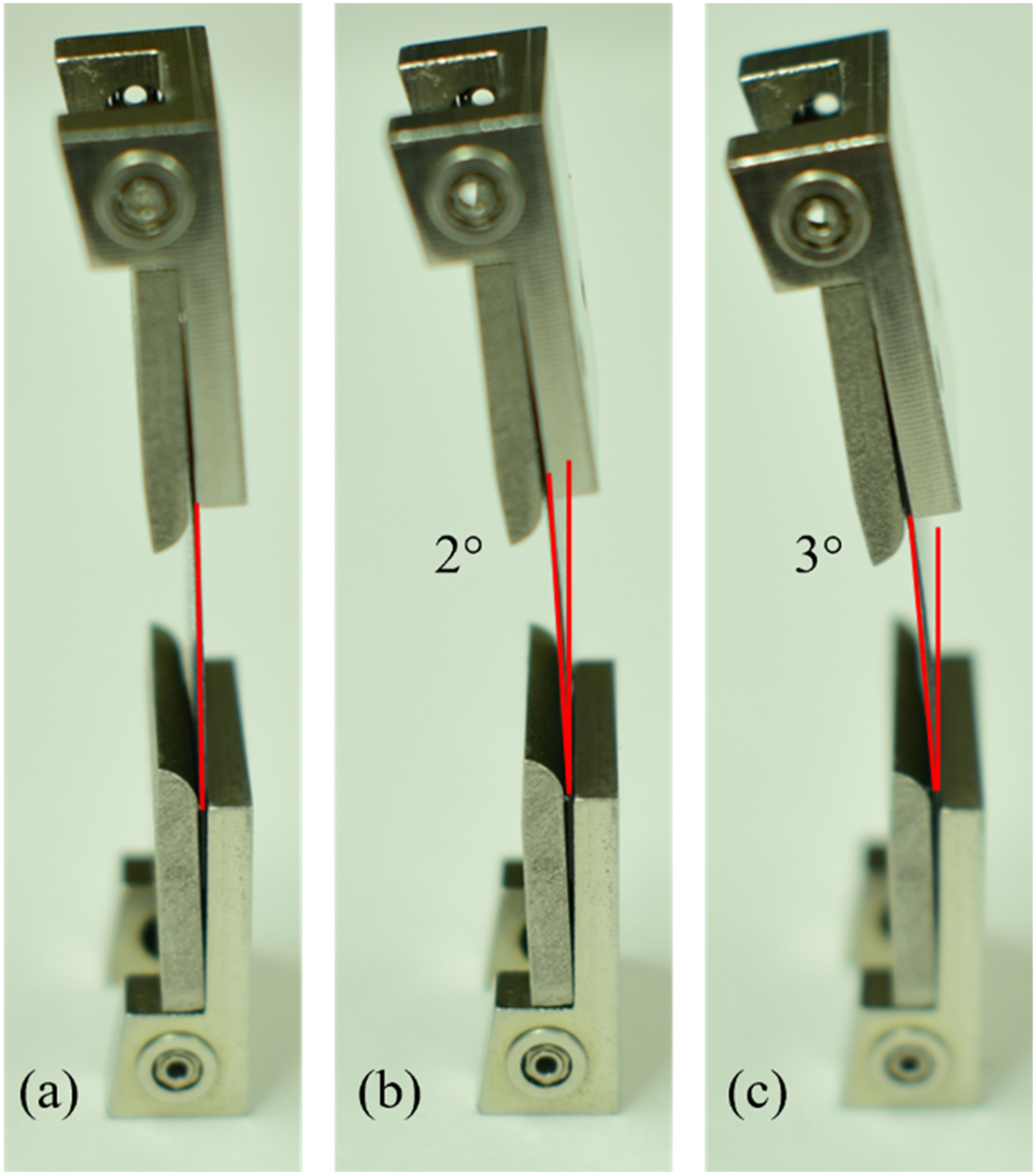
Relaxation behavior
To more effectively compare the stress relaxation and the effect of strains and temperatures on the relaxation behavior, average moment versus time data for UD IM7/PMT-F7 [0°], Astroquartz/PMT-F7 [±45°], Flexlam [±45°/0°/±45°], and Flexlam [±45°/90°/±45°] are presented in Figure 11. This figure includes data for each test specimen at four strains and three temperatures to enable a direct comparison of the relaxation behavior. The data presented is for the 100-min constant displacement period during which the specimen experienced relaxation. The three temperatures, 30°C, 50°C, and 70°C, represent a range of values that may be seen during long-term stowage prior to deployment of DSS. In neat PMT-F7 resin DMA tensile-mode testing
15
clamping issues were also noted at temperatures above 70°C, leading to the upper limit for the CBT temperature. While clearly above room temperature, 30°, 50°, and 70°C are substantially below the 248°C glass transition temperature
12
of the specimens used in this research. Relaxation behavior of (a) UD IM7/PMT-F7 [0°] (b) Astroquartz/PMT-F7 [±45°] (c) Flexlam [±45°/0°/±45°] (d) Flexlam [±45°/90°/±45°] at 0.5%, 1.0%, 1.5%, and 2.0% strain at 30°C, 50°C, and 70°C.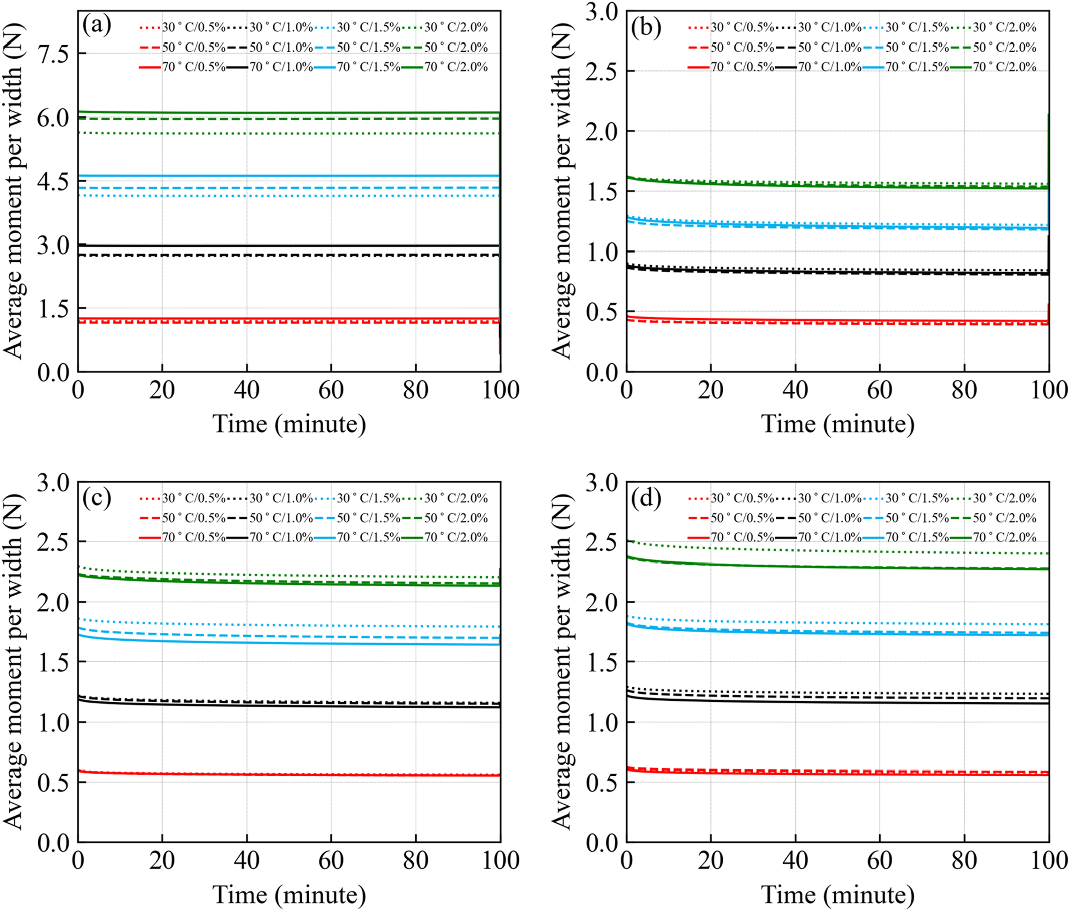
The principal result of evaluating the relaxation (average moment per width vs time) of the UD IM7/PMT F-7 [0°] over all three temperatures and four strains, as shown in Figure 11(a), is to demonstrate that no relaxation occurs during the 100-min hold under any of the conditions evaluated. Once the carbon fibers are introduced to the PMT-F7 neat resin and the load is applied along the fiber direction, the bending of UD IM7/PMT-F7 [0°] lamina, in this case, has become fiber-dominated. Bending the lamina along the fiber direction does not uncoil the molecular structure of the resin enough to lead to rearrangement during the relaxation period due to the complete load transfer to the fiber. As a result, UD IM7/PMT-F7 [0°] laminate behaves elastically and does not show relaxation. However, there is a slight increase in the average moment with the increase in temperature. The increase in the average moment of the UD specimen with increasing temperature, particularly at strain levels of 1.5% and 2.0%, is attributed to the inherent difficulty during testing of UD laminate, primarily stemming from the specimen’s high stiffness. Specifically, the challenge arises in matching the end value of the load in a single program with the beginning load value of the subsequent program. Due to the extreme stiffness of the UD specimen, achieving a seamless transition between load values in consecutive programs becomes challenging. Consequently, this difficulty leads to a noticeable decreasing trend in the load values, contributing to the observed increase in the average moment with elevated temperatures.
Unlike the UD IM7/PMT-F7 [0°], the bending of Astroquartz/PMT-F7 [±45°] laminate is matrix-dominated as the fibers are oriented at ±45° to the loading direction, where the relaxation behavior of the composite laminate is affected by the same manner to the pure matrix polymer.33,34 As a result, the Astroquartz/PMT-F7 [±45°] laminate does show relaxation, as seen in the average moment per width value at constant strain in Figure 11(b). The amount of relaxation in the Average Moment per Width versus Time increases with the applied strain. The relationship is almost flat at 0.5% strain, indicating that the relaxation is essentially imperceptible. As the strain increases, more relaxation is evident. Interestingly, while there is an effect related to the applied strain, the relaxation behavior seems insensitive to the test temperature. The relaxation behavior of Astroquartz/PMT-F7 [±45°] composite laminate is attributed to the rearrangement of the polymer chains and possibly frictional sliding between the fiber and matrix at the fiber-matrix interface.38–41 Also, the relaxation seen in Astroquartz/PMT-F7 [±45°] lamina is comparatively less than the relaxation seen in the same neat resin reported in previous works.12,15 This reduced relaxation is due to a restriction of the polymer chain rearrangement in the composite imposed by the limited volume of matrix material between adjacent fibers and by the effectiveness of the fiber-matrix interface.
Flexlam laminates were manufactured using the UD IM7/PMT-F7 [0°] and Astroquartz/PMT-F7 [±45°], placing the UD IM7 prepreg as the center ply and Astroquartz plain weave prepreg, at ±45°, as each surface ply. The CBT of the Flexlam was conducted in two different orientations, [±45°/0°/±45°] and [±45°/90°/±45°]. The relaxation responses of the two different orientations of the Flexlam laminate are compared in Figure 11(b) and (d). It is observed that both Flexlam laminates show measurable relaxation, and that the magnitude of the Average Moment per Width is effectively the same for both orientations. While at first, this may seem counterintuitive, it is essential to recognize that the Flexlam [±45°/0°/±45°] and Flexlam [±45°/90°/±45°] laminates are both matrix-dominated, as the [±45°] Astroquartz PW are the outer surface plies and see the high flexural strains that are introduced during testing. The carbon fiber ply is at the neutral axis and does not contribute significantly to flexural stiffness. Notably, the relaxation of the Flexlam laminates is slightly less than that is seen for the Astroquartz/PMT-F7 [±45°] lamina. For instance, at 0.5% strain, the average moment reduction of the Flexlam [±45°/0°/±45°] and Flexlam, [±45°/90°/±45°] laminates and Astroquartz/PMT-F7 [±45°] are 6.99%, 5.11%, and 9.12% respectively. The lower amount of relaxation measured in the Flexlam laminates compared to Astroquartz/PMT-F7 [±45°], as shown in Figures 11(b)–(d), is attributed to the inclusion of the elastic UD IM7/PMT-F7 [0°] lamina as center ply. Even though Flexlam laminates contain UD IM7/PMT-F7 [0°] lamina as the center ply and the relaxation tests were conducted at 0° and 90° direction to the center ply orientation, both laminates show no significant differences in the relaxation behavior. This is due to the position of the UD IM7 carbon fiber ply being near the neutral axis; it sees little tensile strain and has only a minimal effect on the resistance to bending.
Effect of temperature and strain on relaxation behavior
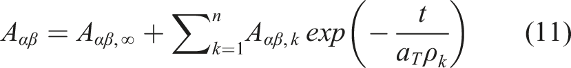
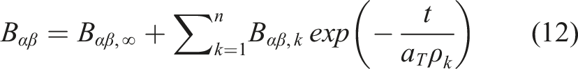
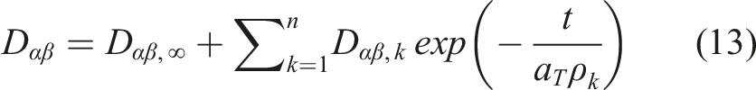
The stress relaxation behavior of a composite is considered to be a time, temperature, and strain-dependent behavior, which results in a decrease in stress at constant strain. In addition, the relaxation process increases with increasing temperature due to the higher molecular mobility provided by increasing thermal energy at an elevated temperature.9,12,26,36,42,43 However, the data presented in Figure 11(b) for Astroquartz/PMT-F7 [±45°] indicates that temperature has no measurable effect on the relaxation. Further, neither of the Flexlam laminates shows an effect of temperature on the relaxation behavior. Since the temperatures used in this effort are well below the glass transition temperature of the thermoset matrix polymer, the thermal energy at those temperatures is insufficient to have a measurable effect on the macromolecular mobility. The measured temperature independence of these laminates limits the ability to apply the time-temperature superposition principle and the viscoelastic models mentioned in equations (11), (12), and (13) to generate a long-term material response.
Flexlam laminates show a very small decrease in average moment value with increasing temperature at strains 1.5% and 2.0% while showing a significant increase in average moment with increasing strain. At higher strain levels, the frictional sliding at the fiber/matrix interface region is expected to become a greater contribution. As a result, interfacial bond scission may occur at the higher strains.44–46 This leads to a faster relaxation rate and a higher magnitude of relaxation at a higher strain level. It is also noticed from the time scale of relaxation data, as shown in Figures 11(b)–(d), that the relaxation rate is highest during the initial few minutes, becoming much slower as the test continues. These phenomena can be explained by associating the short-time relaxation with the mobility of small segments or domains of the polymer chains, whereas the reduced rate of the long-term relaxation is related to the longer-range rearrangement of molecular chains.38,40
Recovery behavior
A comparison of the recovery behavior of the test specimens plotted as average moment per width versus time is shown in Figure 12. These data represent the recovery behavior of each test specimen for four strains at 30°C, 50°C, and 70°C. The comparison considers the 1000 min recovery period at essentially zero displacement. The recovery behavior of UD IM7/PMT-F7 [0°], with the highest value at 0.5% and the lowest value at 2.0%, is shown in Figure 12(a). Even though the recovery is conducted at zero displacement, the average moment value trended slightly negative. It is concluded from the results that the UD IM7/PMT-F7 [0°] shows no measurable recovery trend during the recovery period. This is consistent with the lack of relaxation measured in UD IM7/PMT-F7 [0°] shown in Figure 11(a). However, the 2.0% data does show a slight drop in the moment value during the first 200 min, while all the remaining recovery periods at zero displacements show no significant recovery. Recovery behavior of (a) UD IM7/PMT-F7 [0°] (b) Astroquartz/PMT-F7 [±45°] (c) Flexlam [±45°/0°/±45°] (d) Flexlam [±45°/90°/±45°]at 0.5%, 1.0%, 1.5% and 2.0% strain for each temperature.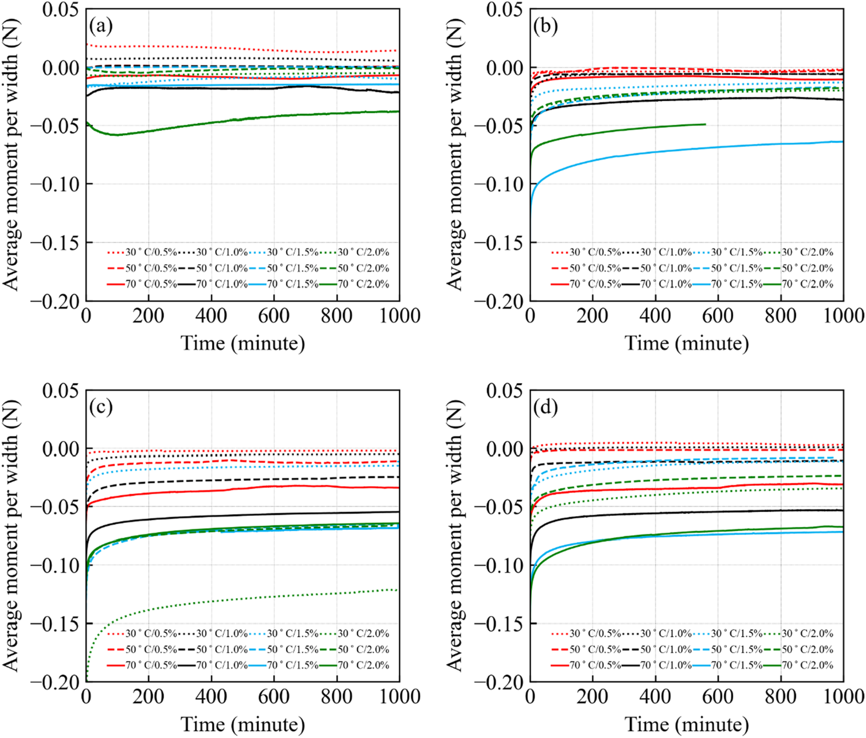
The recovery data of Astroquartz/PMT-F7 [±45°] presented in Figure 12(b) shows that once the applied strain is released, the moment drops to a negative value and returns, to some extent, over the recovery period. As seen from the 0.5% strain data for three temperatures and 1.0% strain data for 30°C and 50°C, the average moment drops to a smaller negative value, returns to its initial position within 200 min, and stays the same during the rest of the recovery period. The results indicate that the recovery moments go to a greater negative value due to the higher magnitude of elastic after-effect as the strain increases.28,36 The increased deviation of recovery moment from zero with increasing strain indicates an incomplete recovery from the relaxation, induced during 100 min hold period, which results in the residual curvature observed in the specimens, as shown in Figure 10.
The recovery behavior of Flexlam [±45°/0°/±45°] and Flexlam [±45°/90°/±45°] laminates are presented in Figures 12(c) and (d). The trend in the recovery data is the same as seen in the Astroquartz/PMT-F7 [±45°] lamina, and the moment drops to a negative value once the strain is released and then recovers over time. The shapes of the recovery plots are consistent with the relaxation trends, indicating that the highest strain and temperature result in the longest time for the moment to stabilize. Comparing the recovery behavior of the Flexlam [±45°/0°/±45°] and Flexlam [±45°/90°/±45°] laminates, it is seen that there is no measurable difference in the recovery moment value or the trend. However, the recovery data cannot be grouped by strain and temperature. Thus, it is difficult to directly compare the results at the three temperatures because the pre-strain condition is slightly different for each test specimen, resulting in a discrete recovery response. Overall, recovery data of Astroquartz/PMT-F7 [±45°], Flexlam [±45°/0°/±45°], and Flexlam [±45°/90°/±45°] laminates indicate that most of the recovery occurs during the first 200–250 min and the plots plateau during the remainder of the recovery period. It is also observed in the Astroquartz/PMT-F7 [±45°], Flexlam [±45°/0°/±45°] and Flexlam [±45°/90°/±45°] laminates that the longest times of recovery are at the highest strain and temperature (70°C). Conversely, the data for 30°C indicates the most rapid recovery. The recovery requires a longer time at higher temperatures and strain due to the gradual scission of the interfacial bond that occurred during the relaxation period.44–46
Average moment versus curvature data for the UD IM7/PMT-F7 [0°], Astroquartz/PMT-F7 [±45°], Flexlam [±45°/0°/±45°], and Flexlam [±45°/90°/±45°] laminates incorporate both the relaxation and recovery for each strain step as presented in Figure 13. The variation in thickness between the different materials negates direct quantitative comparisons. However, the average moment versus curvature results give additional insight into the viscoelastic response. It is worth mentioning that Figure 13 only shows information for the tests performed at 70°C as it has been shown that the greatest differences are noted at the highest test temperature. As presented in Figure 13, for the fiber-dominated UD IM7/PMT-F7 [0°] laminate, the average moment versus curvature plots follow the same path while loading and unloading for each strain. So, there is essentially no area enclosed during loading and unloading in any of the four strain steps. This lack of enclosed area within the loading and unloading curves is consistent with a lack of hysteresis, which is an indication of the elastic response, also indicated in Figure 11(a). However, for the remaining laminates, as presented in Figures 11(b)–(d), the average moment versus curvature plots do not follow the same path while loading and unloading, resulting in hysteresis loops. The hysteresis is a result of the viscoelastic nature of these matrix-dominated laminates and energy absorbed during loading and unloading cycle for each strain is given by area within the loop. Qualitatively comparing the Astroquartz/PMT-F7 [±45°] to the two Flexlam laminates, it seems that there is slightly more hysteresis indicated for the Astroquartz/PMT-F7 [±45°] which is consistent with the trends previously discussed. Average moment per width versus Curvature data for four strains at 70°C (a) UD IM7/PMT-F7 lamina (b) Astroquartz/PMT-F7 laminate (c) 0° Flexlam laminate (d) 90° Flexlam laminate.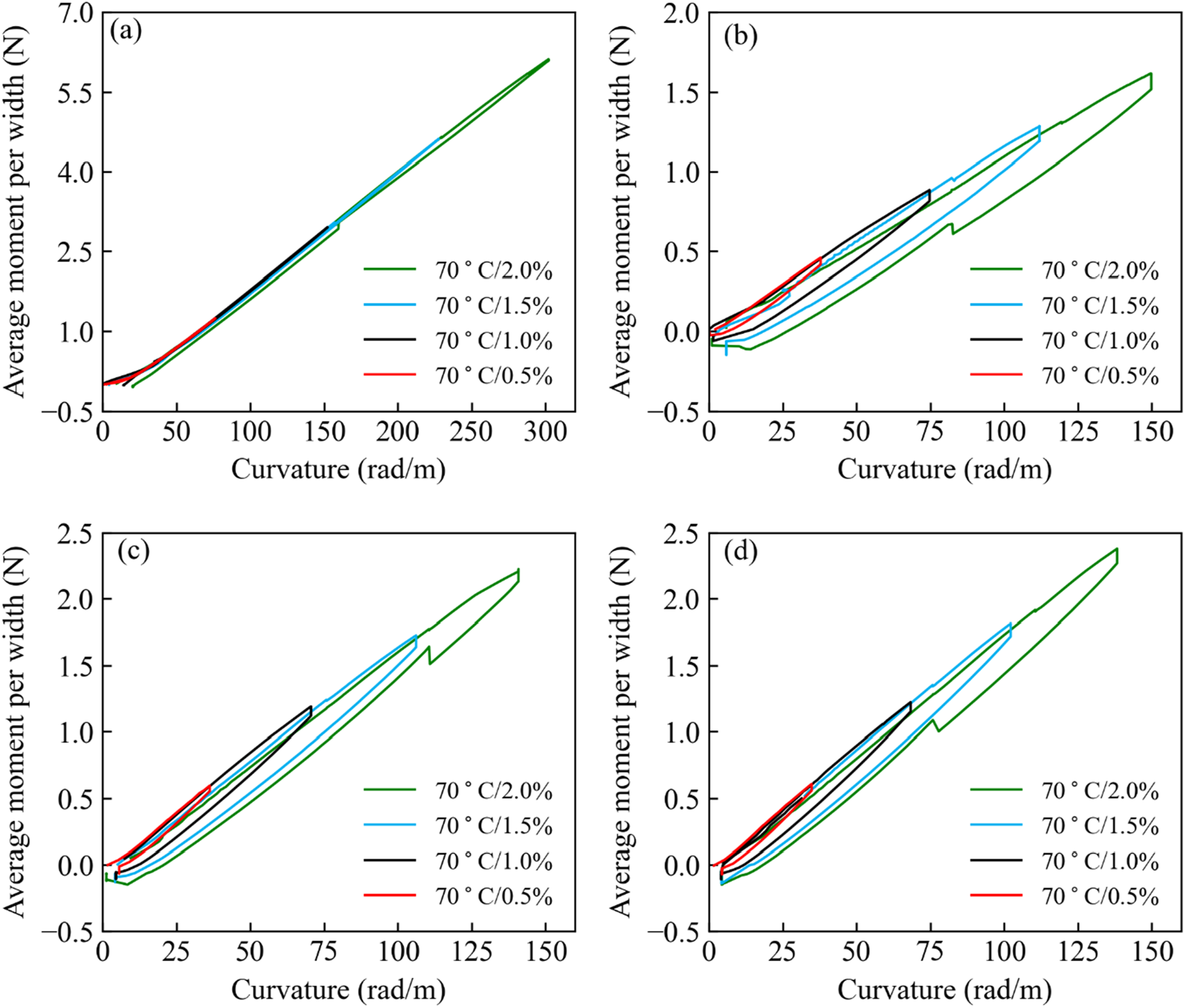
Conclusions
The present study has experimentally investigated the time, temperature and strain-dependent relaxation and recovery behavior of the Flexlam laminate and the associated individual plies at strains up to 2% and temperatures ranging from 30°C to 70°C in a DMA, using the stepped strain extended recovery approach in the column bending test (CBT) mode. The testing was conducted at four different strains, 0.5%, 1.0%, 1.5%, and 2.0%, and three temperatures of 30°C, 50°C, and 70°C. The raw data acquired from the tests was in the form of the load related to the applied displacement. Using CBT kinematics equations, the raw data was converted to the average moment per width versus time to evaluate the time, temperature, and strain dependence of relaxation and recovery behavior.
The relaxation and recovery behavior of the fiber-reinforced polymer composites tested was affected by both fiber orientation and matrix resin time dependency. While the fiber-dominated UD IM7/PMT-F7 [0°] tests showed no relaxation over the range of temperatures and strains, the matrix-dominated Astroquartz/PMT-F7 [±45°] specimen showed significant relaxation in this same range of temperatures. The Flexlam laminates, manufactured with the UD IM7/PMT-F7 [0°] ply placed at the center along with the Astroquartz/PMT-F7 [±45°] at the outer surfaces also show measurable relaxation in flexural testing regardless of the test direction of the center UD IM7 carbon fiber reinforced ply. This is due to the concentration of the strains at the outer surfaces being introduced into the Astroquartz/PMT-F7 [±45°] plies resulting in relaxation behavior indicative of the matrix-dominated Astroquartz/PMT-F7 [±45°]. A key outcome of the data acquired using the DMA-based CBT for Astroquartz/PMT-F7 [±45°] and for the Flexlam laminates is that relaxation behavior is more time and strain-dependent than the temperature-dependent within the range of temperatures evaluated. This test temperature range was meant to be consistent with the stowage temperature used for DSS. Overall, the new DMA-based CBT approach allows experimental determination of the relaxation and recovery behavior of thin-ply HSC materials with the laminate thicknesses that are more closely aligned with those actually used for DSS application, which was not possible prior in the load cell-based CBT method.
Future research
The current study has highlighted the relaxation of composite at only two fiber orientations. As the stowage and deployment of the DSS are tailored by fiber orientations and matrix’s viscoelasticity, future research could delve into a more comprehensive exploration of relaxation behavior by systematically varying both fiber orientations and matrix materials. This could involve conducting experiments and simulations to understand how different combinations affect the overall relaxation of the composite laminate. In addition, there is potential for further refinement and sensitivity analysis of this technique, particularly concerning its ability to characterize the effect of fiber-matrix interface bonding on relaxation behavior at high strain rates.
Footnotes
Acknowledgments
The authors would like to acknowledge Dr Juan Fernandez, NASA LaRC, for his collaboration, input and imparted expertise during this effort. This work was funded exclusively through the NASA STTR Program, contract number 80NSSC20C0025.
Author contributions
Declaration of conflicting interests
The author(s) declared no potential conflicts of interest with respect to the research, authorship, and/or publication of this article.
Funding
The author(s) disclosed receipt of the following financial support for the research, authorship, and/or publication of this article: This work was funded exclusively through the NASA STTR Program, contract number 80NSSC20C0025. The author(s) received no financial support for the research, authorship, and/or publication of this article.
Data availability statement
The raw data and processed data required to reproduce these findings will be available to readers upon request to the first author.