
Abstract
To adapt to harsh engineering environments, the use of structural components with fiber-reinforced polymer (FRP) grid-reinforced ultra-high-performance concrete (UHPC) is considered a new development trend. Twelve FRP grid-reinforced UHPC I-beams are fabricated to investigate the effects of the thicknesses of FRP grids (0 mm, 1 mm, 3 mm, and 5 mm) and the steel fiber contents of UHPC (0%, 1%, and 2%) on their flexural performance. Four-point bending tests are conducted to obtain the failure modes, load-deflection characteristics, and strain responses of each testing beam, and a simplified calculation method for cracking loading and flexural bearing capacity is proposed. The results reveal that the increase in FRP grid thickness, the ultimate load bearing capacity of FRP grid-reinforced UHPC structural beams increases and the ductility also can be enhanced. The presence of steel fiber effectively inhibits the cracking and increases the first cracking load of the beam during the test process, although its influence on the ultimate bearing capacity is limited. Besides, until to the cracking stage, there is no noticeable change in the tensile strain of the FRP grids as the applied load increases. It has been used to simplify theoretical calculations, which shows good agreement with the experimental results.
Keywords
Introduction
In recent years, there has been a significant increase in the construction of marine and coastal infrastructure, including bridges, ports, and offshore platforms. However, it has been discovered that traditional reinforced concrete (RC) structures face various problems when extensively used in those engineering. The low tensile strength of common concrete makes the tensile zone of reinforced concrete beams prone to cracking, affecting the load-carrying capacity and causing issues such as corrosion of steel reinforcements. In addition, the cumbersome nature of RC structures makes them difficult to construct in harsh marine environments, resulting in increased costs for material transportation and on-site construction labor. Therefore, the focus has been shifted to using ultra-high performance concrete (UHPC) materials and fiber-reinforced polymer (FRP) materials to improve this situation.
UHPC is a type of concrete that is characterized by its exceptional mechanical and durability properties, including high compressive strength (over than 100 MPa), low permeability, and excellent durability. By analyzing the base materials and additives, Rossi concluded that the total number of steel fibers increases the specific surface area in the UHPC matrix, leading to better mechanical performance. 1 Lao et al. designed and developed a type of UHPC with strain-hardening behavior by adjusting the fly ash-to-slag ratio and straight steel fiber content, and the tensile ductility of the material can be controlled within the range of 0.35%–0.55%. 2 Considering the construction conditions of coastal engineering, Teng et al. designed and experimentally verified the strength properties of UHPC with seawater sea-sand for the marine environment to demonstrate its feasibility. 3 Various experimental studies have shown that adjusting the material proportions, such as the type and material of steel fibers,4,5 municipal solid and polymeric waste,6–8 cementitious components,9,10 can significantly improve the micro-structure of UHPC, and making it more flexible in different application scenarios.
According to the characteristics of structural members, UHPC is selectively used in the design of columns, 11 panels, 12 and slabs. 13 As the most common flexural member in structure, Yang et al. made 14 UHPC beams with different reinforcement ratios and found that the flexural capacity was even affected by the placing method of the UHPC and the steel fiber-reinforced UHPC is proved to be effective at controlling cracks and exhibiting a ductile post-cracking behavior. 14 Chen et al. conducted bending tests on UHPC PI-girders with joint to optimize the UHPC section. 15 Dong et al. proposed a new type of small-sized UHPC I-beam, whose bottom flange was hybrid shear reinforced with an embedded steel plate and BFRP sheets and the web was reinforced with embedded steel threaded rods and vertically surface-bonded basalt fiber reinforced polymer (BFRP) sheets. 16 There is a growing recognition that the high compression strength characteristics of UHPC can be effectively utilized on the cross-section. To better reduce structure weight and improve cost-effectiveness, various tensile property materials are also being tested for application in UHPC, aiming to optimize the overall structural characteristics and functionality.
FRP is a composite material composed of continuous fibers and resin matrix. Due to its advantages of high tensile strength, high durability, lightweight, and resistance to harsh environmental conditions, FRP products are widely used in retrofitting of existing concrete structure, such as FRP plates, 17 FRP jackets, 18 FRP rebars,19,20 FRP tubes,21,22 and FRP grids. 16 Ding et al. tested the load-carrying ability of beams reinforced with FRP grids, steel, and carbon fiber sheet, which showed that FRP grids have better competitiveness. 23 Due to the resistance contribution provided from two orthogonal directions, the shear strengthening effect of FRP grids on RC beams was revealed by Guo et al. based on seven test beams. 24 Zhang et al. found that carbon-FRP (CFRP) grid-reinforced engineered cementitious composites (ECC) specimen substantially improved the cracking load by 53.4%–92.4% and the maximum load by 4.4%–34.4% through 10 test beams. 25 Existing studies have also indicated that FRP grids have a good bond with high-strength cementitious matrix, so it is possible to use FRP grids in UHPC to improve the mechanical performance of structure components.
From the perspective of the combined utilization of these materials, researchers have carried out some research on the combined application of FRP grids and UHPC. He et al. investigated the bond behavior of the interface between FRP grids and concrete substrate, which is influenced by the width ratio of the FRP grids to concrete specimens, FRP grid stiffness, and bonding material type. 26 Ye et al. conducted experiments to assess the flexural and tensile behavior of FRP grid-UHPC composite plates, both with and without the inclusion of steel fibers in the UHPC mix. The results demonstrated that the steel fibers prevent the cover from spalling off and prevent debonding from causing the cover to pass through the openings of the FRP grid in the UHPC mix. 11 Zeng et al. preliminary tested FRP grid-UHPC composite plates and found that the presence of FRP grids prevented load deterioration and led to a strong strain hardening response in the second segment of the load-deflection curves, where the ultimate flexural capacity can be enhanced by over 150%. 27 Furthermore, pre-coated steel fibers and non-metallic fibers have also been proposed as substitutions for metallic steel fibers in the UHPC mix to accommodate complex and harsh environmental conditions.5,28
Based on the background information mentioned above, this study involves an I-shaped beam member designed with FRP grids-reinforced UHPC. The innovation of this research is that the lightweight brought by the design of the UHPC I-shaped beam and the performance improved by the substitutions of FRP grids. Twelve FRP grid-reinforced UHPC I-beams are fabricated, with different FRP grid thicknesses (0 mm, 1 mm, 3 mm, and 5 mm) and UHPC steel fiber contents (0%, 1%, and 2%). Four-point bending tests are conducted to investigate the failure modes, load-deflection curves, and strain responses with the aim to better adapt to the mechanical characteristics of both materials. The calculation method of the cracking load and flexural bearing capacity of the FRP grid-reinforced UHPC I-beam was also studied. The results of this research can provide a basis for the design of the bearing capacity and deformation capacity of UHPC beams reinforced by FRP grids in some complicated infrastructures.
Experimental program
Specimen design
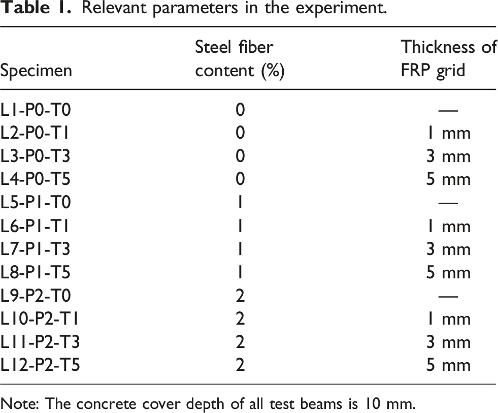
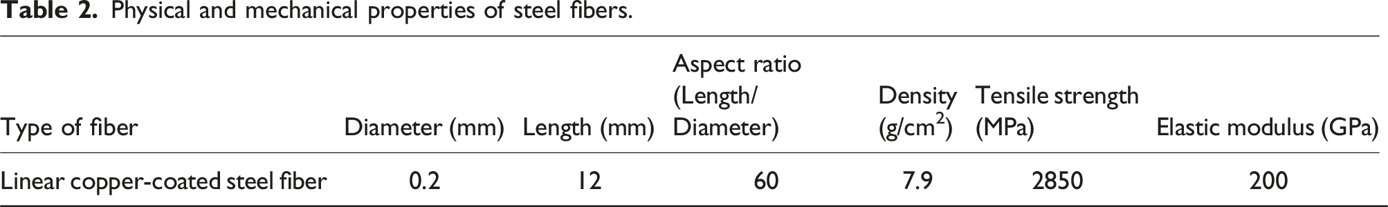
A total of 12 FRP grid-reinforced UHPC I-beams were designed for this experiment, with a total length of 1500 mm and an effective span of 1300 mm, as shown in Figure 1(a). The grid adopted for the test beam is a basalt FRP grid with an overall size of 200 mm × 1450 mm. The mesh size of grid is 50 mm × 50 mm and the leg width is 10 mm, as shown in Figure 1(b). During the preparation of the test beams, the grid was fixed using a 10 mm thick bolt pad attached to the mold. The test beams were divided into four categories based on FRP grid thicknesses, which were 0 mm, 1 mm, 3 mm, and 5 mm. Additionally, the 12 test beams were also divided into three groups based on the steel fiber content in UHPC, which were 0%, 1%, and 2%. The linear copper-coated steel fibers, as shown in Figure 1(c), are used during UHPC mixing. The relevant parameter setting and steel fiber information are shown in Tables 1 and 2, where one beam was left without any added steel fiber content as a blank control beam. Design of the test specimen. (a) Loading diagram of the test specimen, (b) Dimensions of the basalt FRP grid, (c) Linear copper-coated steel fiber, and (d) Test beam templates and casting. Relevant parameters in the experiment. Note: The concrete cover depth of all test beams is 10 mm. Physical and mechanical properties of steel fibers.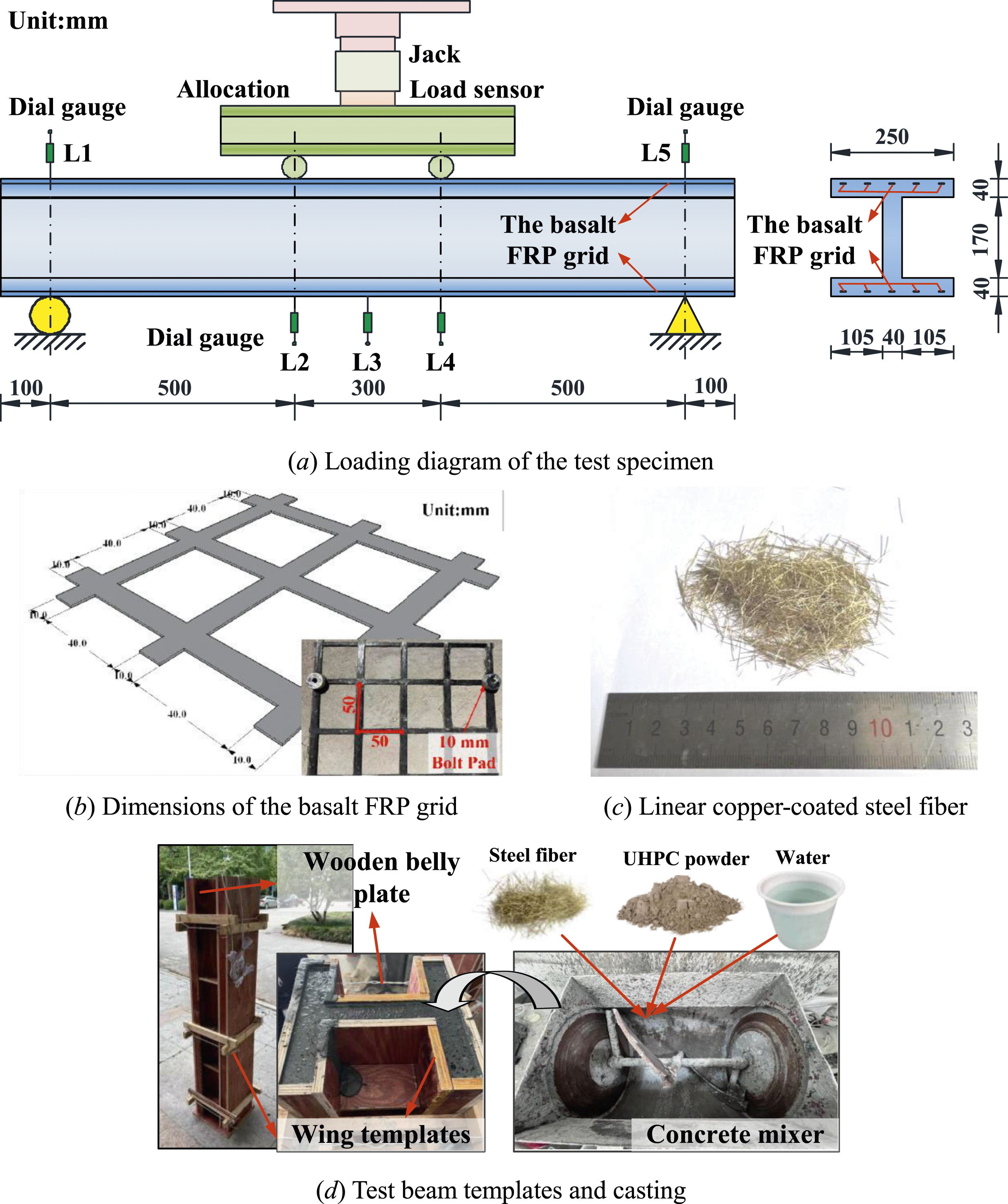
To standardize the production of structural specimens, wooden belly plate and wing templates connected by steel nails were used, as shown in Figure 1(d). The joints were sealed with silicon sealant to ensure surface smoothness, and lubricant was applied to reduce the flow resistance of UHPC. Wooden ribs were nailed around the structural template, and steel wire was used to tie the wooden ribs tightly to reinforce the template and prevent swelling during casting. The water to UHPC powder ratio is controlled at 0.1, and the steel fibers are added during the mixing process in the concrete mixer. The pouring of the specimen begins after stirring for more than 10 minutes to ensure that the steel fibers are evenly distributed in the UHPC. Making use the self-compacting nature, the UHPC is poured from top to bottom into the mold, and no mechanical vibration is needed. The test beams were covered with plastic film and cured in room temperature for about 28 days until testing.
Strength properties of materials
During the casting of the test beams, three cubes (100 mm × 100 mm × 100 mm) and three prisms (100 mm × 100 mm × 400 mm) were prepared for each batch of UHPC with different steel fiber contents. The UHPC cubes and prisms were cured under the same conditions as the test beams, and tested under compression and flexure, respectively, according to Chinese standard GB/T 50081,
29
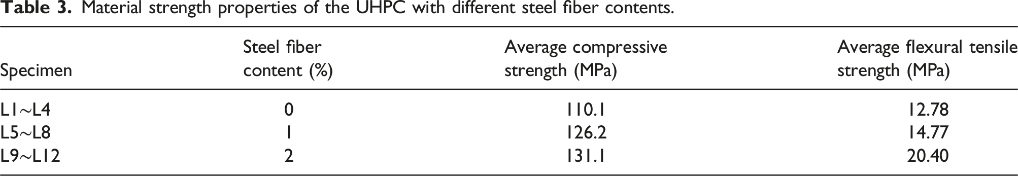
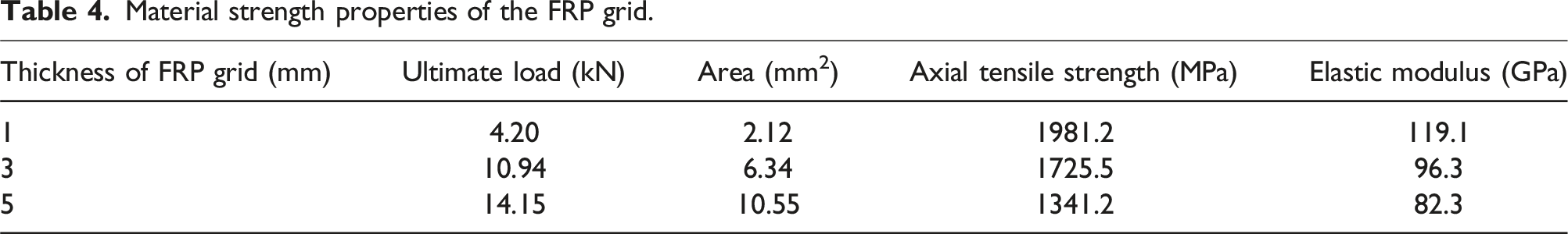
as shown in Figure 2(a). Table 3 lists the average compressive strength and flexural tensile strength of UHPC with different steel fiber contents. By referring to the test method of grid axial tensile strength proposed in “Fiber Reinforced Composite Material Grid for Structural Engineering” GB/T 26743
30
and GB/T 36262,
31
the tensile strength of FRP grid is obtained through the tensile test of FRP grid, as listed in Table 4. Material strength test setup. (a) Flexural tensile strength testing of UHPC, (b) Tensile test of FRP grid. Material strength properties of the UHPC with different steel fiber contents. Material strength properties of the FRP grid.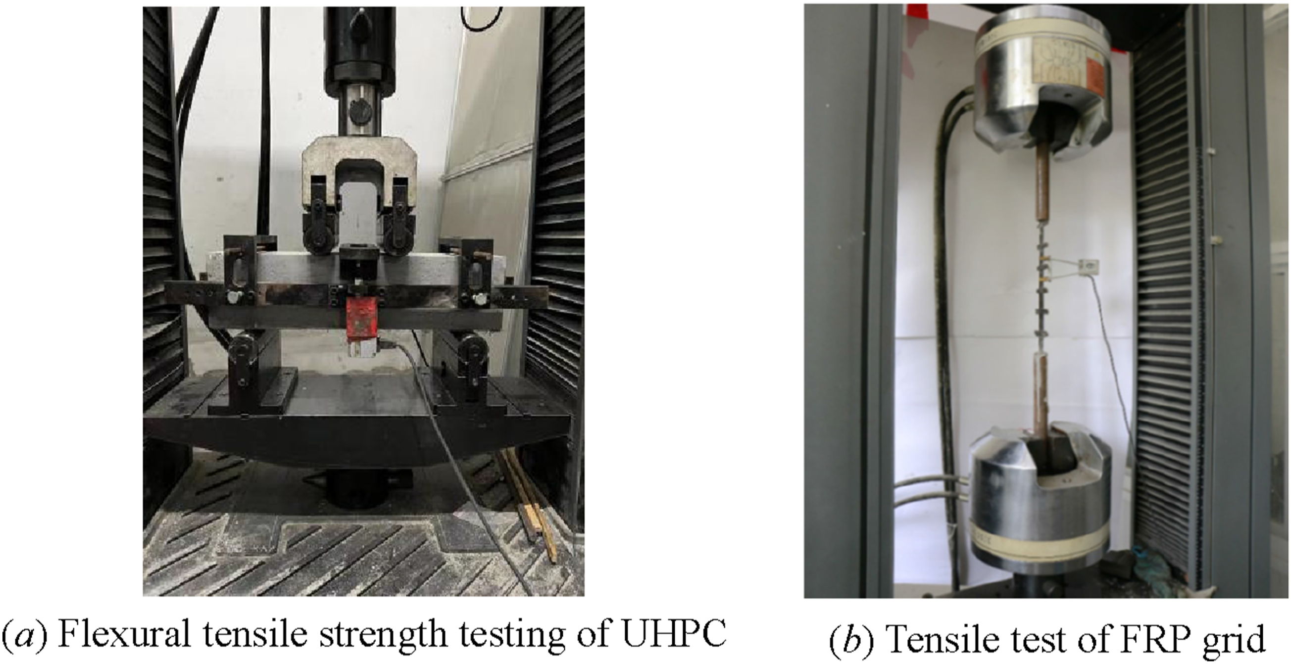
Test set-up and loading scheme
Arrangement of sensors
To measure the deflection at different locations of the test beam, five displacement transducers (Labeled as L1, L2…L5) were installed at the support, loading point, and mid-span, respectively, and each transducer was placed at the middle line of the beam surface, as shown in Figure 1(a). The displacement transducer at the support was used to measure the settlement of the test beam at the support, while the displacement transducers at the loading point and mid-span were used to measure the deflection of corresponding cross sections. A total of 11 strain gauges (Labeled as W1, W2…W11) were installed on the surface of the UHPC I-beams at mid-span cross section, with three strain gauges evenly distributed on the top and bottom surfaces, respectively, one strain gauge was placed on the upper and lower flanges, respectively, and three strain gauges were evenly distributed on the web of the section. Besides, for the FRP grids, strain gauges (Labeled as N1, N2…N5) were attached to the center of each longitudinal leg of the bottom flange grid. The arrangement of strain gauges can be tracked in Figure 3. The arrangement of strain gauges.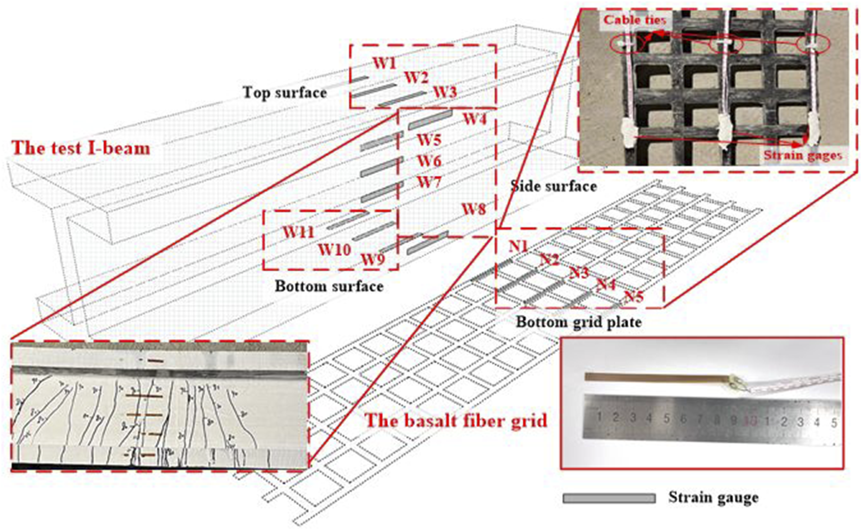
Loading scheme
To test the bending capacity of FRP grid-reinforced UHPC I-beams, a four-point symmetric loading method was utilized, with the pure bending span length of 300 mm. The experiment was conducted in the structural laboratory of Wenzhou University. Prior to the official start of the experiment, the test beam was preloaded to 10 kN and then unloaded to ensure that all systems were functioning normally. For the flexural test, a load control followed by displacement control loading method was adopted. The loading was initiated with a staged loading method of 10 kN as the first level. After the test beam exhibited non-elastic damage (such as crack damage), the loading method was changed to displacement control until the test beam was damaged. The loading rate for the load control was 0.5 kN/min, and the loading rate for the displacement control was 0.5 mm/min. This loading method was adopted to ensure stable experimental process while controlling the speed of the experiment, ensuring the accuracy of experimental data. During the experiment, 2–3 min were required after each level of loading to observe and mark the cracks. The data acquisition instruments for displacement sensors, load sensors, and strain gauges were shown in Figure 4, and the sampling frequency was 1 Hz. I-shape beam model test system.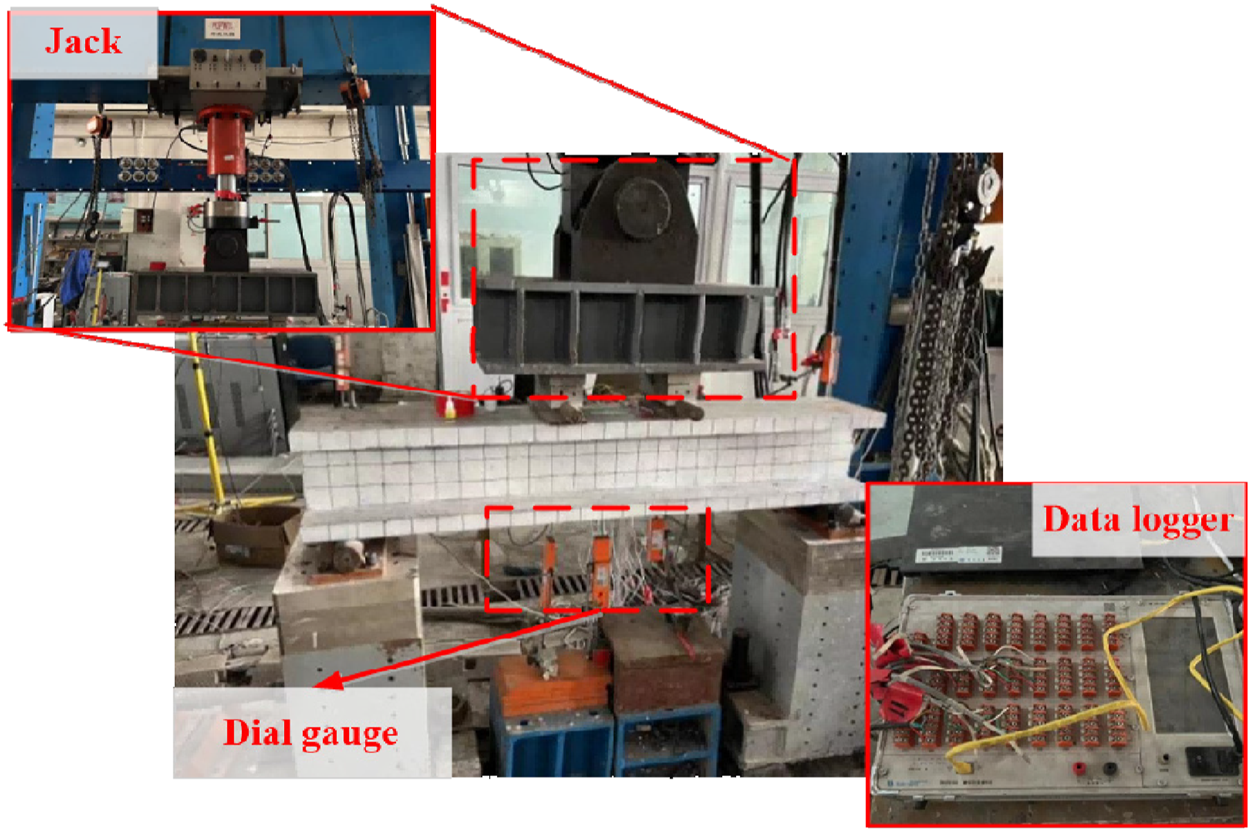
Test results
General behavior
Figure 5 shows the damage situation of beam specimens regarding the ultimate load. For the control group (L1-P0-T0), the experimental beam was in the elastic stage during the initial loading and no obvious cracks appeared. However, when the load on the specimen reached 28.9 kN, the left end of the loading point on the left side of the specimen suddenly fractured, with the main crack running through the entire section. In comparison, for the experimental beam with 5 mm thick FRP grids (L4-P0-T5), the first crack appeared at the bottom of the middle span with a crack width of about 0.04 mm when the load reached 36.3 kN. As the test progressed, when the load reached 50 kN, the first oblique crack appeared on the right end support and the middle of the same-side loading point, and the number of cracks at the middle span increased from 1 to 4. During the process of reaching the ultimate load of 67.9 kN, oblique cracks appeared successively on the left end support and loading point, and the main oblique crack on the right side continued to develop until it penetrated the entire section. Therefore, it can be seen that the FRP grids changed the performance of the UHPC I-beam, and the failure mode of the experimental beam has shifted from brittle fracture of UHPC to a combination of UHPC cracking and BFRP rupture. Failure modes regarding the ultimate load. (a) L1-P0-T0, (b) L4-P0-T5, (c) L5-P1-T0, (d) L8-P1-T5.
In addition, the failure modes of the UHPC beam (L5-P1-T0) with 1% steel fiber content and the FRP grid-reinforced UHPC I-beam (L8-P1-T5) are compared. The results showed that adding steel fibers can enhance the connection of the UHPC base material and increase the ultimate load bearing capacity of the structure, though the effect of steel fibers is limited. In contrast, FRP grids have a more significant effect in improving the bending performance of the structure. For the L5-P1-T0 specimen, the first crack appeared at the bottom of the span when the load reached 51.2 kN. As the test continued, the crack started to propagate rapidly upward with the sound of steel fiber failure. When the load reached 63.3 kN, the specimen suddenly fractured with the main crack penetrating the entire section. On the other hand, the crack propagation of the L8-P1-T5 specimen was much slower. The first crack appeared in the pure bending section when the load reached 50.1 kN, with a crack width of about 0.02 mm. As the load increased, cracks continued to appear and propagate. Finally, when the load reached 132.7 kN, the mid-span crack extended to the top of the specimen, and the load bearing capacity and deflection reached the maximum values. At last, the mid-span deflection reached 16.15 mm, and the specimen failed, but the overall ductility was good. Therefore, it is necessary to improve the bending performance of the structure through FRP grid in component design to achieve better material component performance.
Figure 6 shows the width of the main crack development of the test UHPC I-beams under different steel fiber contents and FRP grid thicknesses during loading. For safety reasons, crack width measurements were not performed on some test beams at higher loads. The trend analysis of the available data shows that the crack initiation load of the FRP grid-reinforced UHPC I-beams increases with increasing steel fiber content. For example, at a load of 70 kN, the maximum crack width at the mid-span section of the FRP grid-reinforced UHPC I-beams containing 1% and 2% steel fibers are 0.22 mm and 0.10 mm, respectively, indicating that the steel fibers play a good role in crack prevention during the load bearing process. At the same time, when the steel fiber content is the same, the effect of different FRP grid thicknesses on the first cracking load of the structure is not significant, but it will affect the width of the crack during loading. For example, when the steel fiber content is 1% and the load is 60 kN, the crack width of the test beams with carbon fiber grid thicknesses of 1 mm, 3 mm, and 5 mm are 0.22 mm, 0.16 mm, and 0.12 mm, respectively. The width of the main crack development of the test UHPC I-beams. (a) Different steel fiber contents, (b) Different FRP grid thicknesses.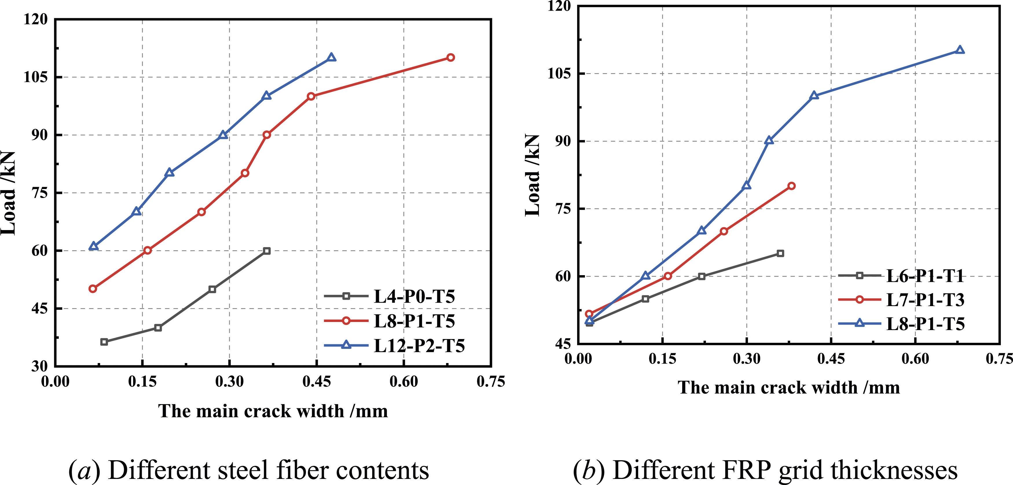
Load deflection curves
The load deflection curves of the test UHPC beams with different steel fiber contents and FRP grid thicknesses are illustrated in Figure 7. According to the results, the test beam’s deflection until the initiation of cracks increased linearly and was proportional to load. After that, the tested UHPC beams experienced a decrease in stiffness due to cracking of the cross-section, resulting in a decrease in the slope of the load deflection curve. This stage is named as hardening stage as the load still increases with deformation. In the final stage, the beam failed and the peak load was obtained. Unlike traditional steel reinforcement reinforced UHPC beams, there was no obvious yielding plateau during the test,14,32 where the structural stiffness decreased twice due to the yielding of the steel bars. Comparison of the experimental groups with different steel fiber contents reveals that the hardening stage of the UHPC beams without grids or with a grid thickness of 1 mm is very narrow. The test UHPC beams immediately reached the ultimate load and the maximum deflection after elastic stage. This indicates that the FRP grids will provide tension strength in strengthening the UHPC beam during the bending ductile stage and could obtain higher ultimate loads with increasing thickness. Load deflection curves of FRP grid-reinforced UHPC I-beam. (a) With 0% Steel fiber content, (b) With 1% Steel fiber content, (c) With 2% Steel fiber content.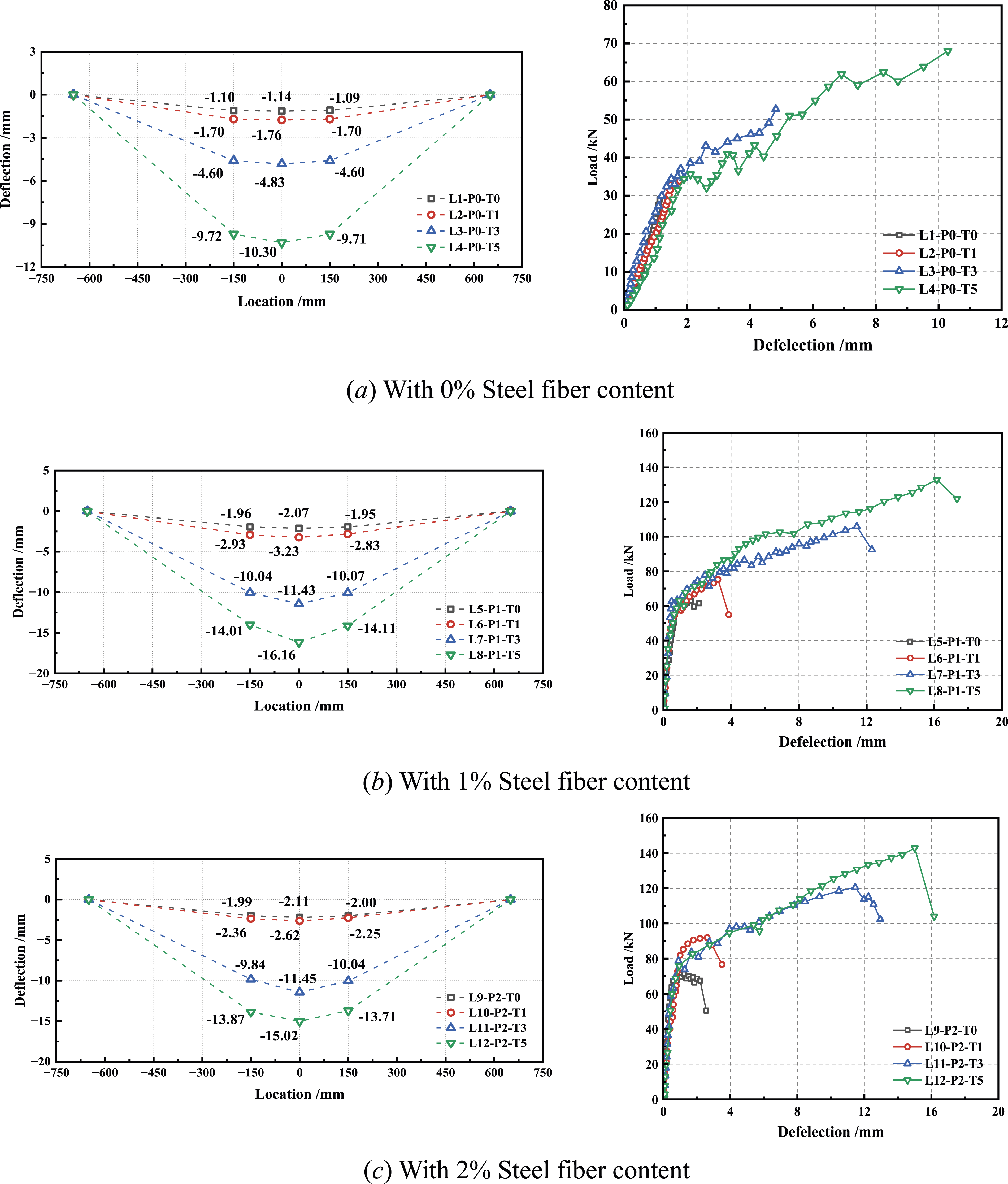
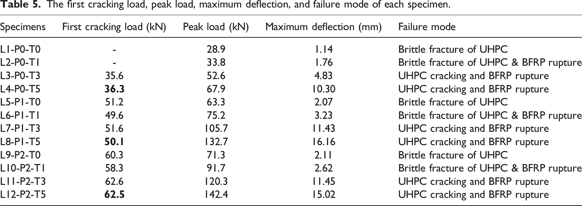
The first cracking load, peak load, maximum deflection, and failure mode of each specimen.
Strain responses
By attaching strain gauges to the surface of the test beams, the distribution of strain along the cross-sectional height of each test beam can be obtained, as shown in Figure 8. In FRP grid-reinforced UHPC concrete I-beams, strain measurements taken near the top surface show negative strain, while those taken near the bottom surface show positive strain. Moreover, as the load increases, the strain across the cross-section also increases, aligning with the bending beam fundamental principle, where the top surface is under compression and the bottom surface is under tension. At the same time, before reaching the first cracking load value, the strains along the cross-section of the reinforced beam under 10 to 50 kN load conditions exhibited a good linear distribution characteristic, and the beam structure was in the elastic phase. Therefore, plane section assumption is valid before cracking of FRP grid-reinforced UHPC beam. Further analysis of the fiber content and grid thickness reveals that they contribute to the improvement of the overall performance of the test beams. Such as Figures 8(e) to (g), under the same applied load, the test beams with FRP grids exhibit a more uniform distribution of section strains. Distribution of UHPC I-beam strain with section height. (a) L5-P1-T0, (b) L6-P1-T1, (c) L7-P1-T3, (d) L8-P1-T5, (e) L9-P2-T0, (f) L10-P2-T1, (g) L11-P2-T3, (h) L12-P2-T5.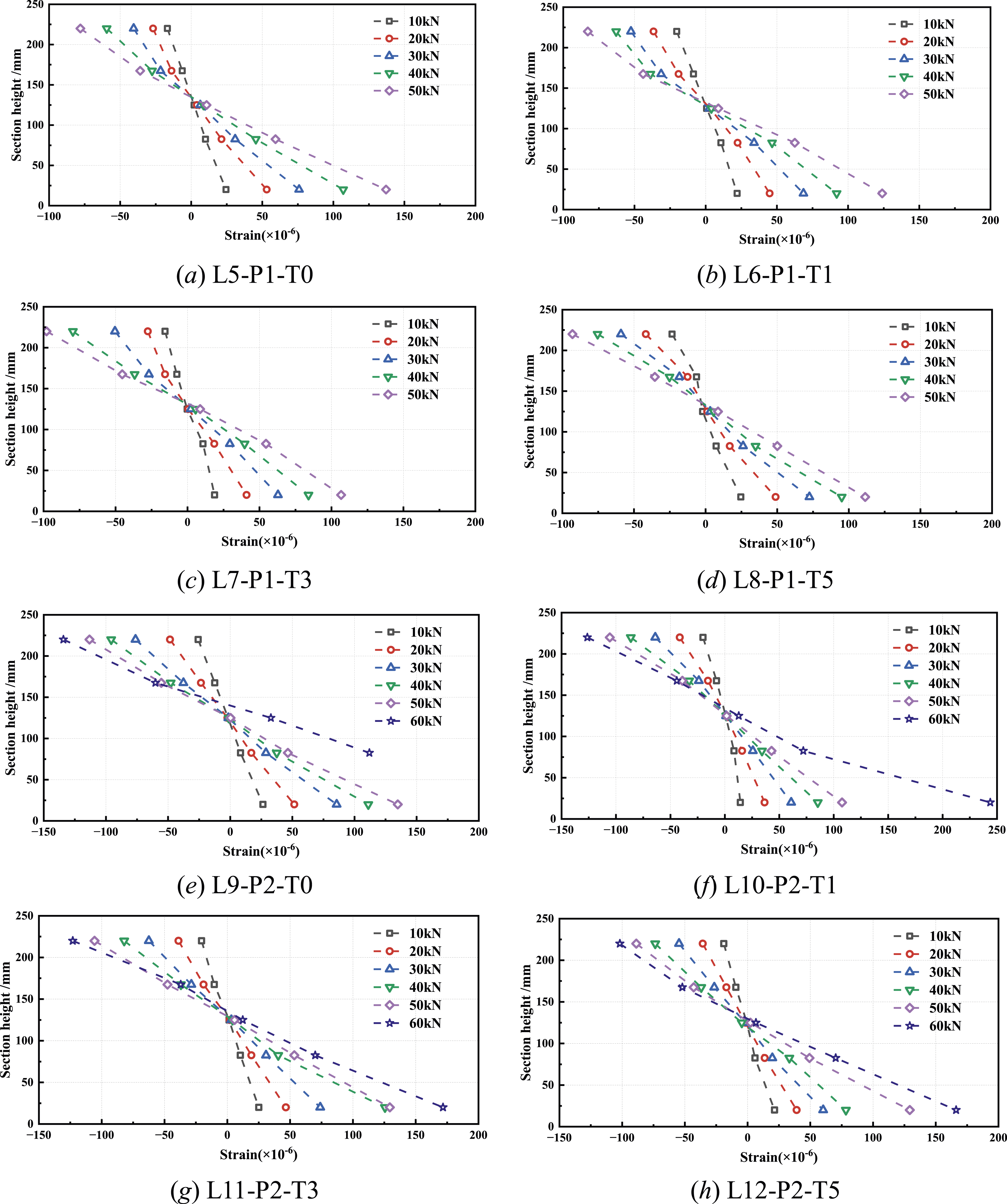
Furthermore, upon analyzing the strain results on the bottom FRP grid of the test beams (Figure 9), it can be observed that the grid strain exhibits a distinct three-stage distribution characteristic. Initially, before reaching the first cracking load, the primary source of tensile stress in the test beam originates from the UHPC itself. During this stage, there is hardly any noticeable change in the tensile strain of the grid as the applied load increases, and the strain growth trend remains consistent across different conditions. As cracks begin to appear on the beam’s bottom surface, the FRP grid starts to provide the primary tensile stress in the bent beam. The strain in the grid gradually increases with the increasing load. Additionally, owing to the difference in grid thickness, the growth rate of the 5 mm thick grid exceeds that of the 1 mm thick grid condition. This suggests that UHPC beams with thicker grids possess a higher ultimate load-carrying capacity. Besides, the strain in the FRP grid decreases at the third stage when the flexural UHPC beam reaches its ultimate load bearing capacity and experiences failure. Strain of the FRP grid of each test beam in the pure bending region. (a) With 1% Steel fiber content, (b) With 2% Steel fiber content.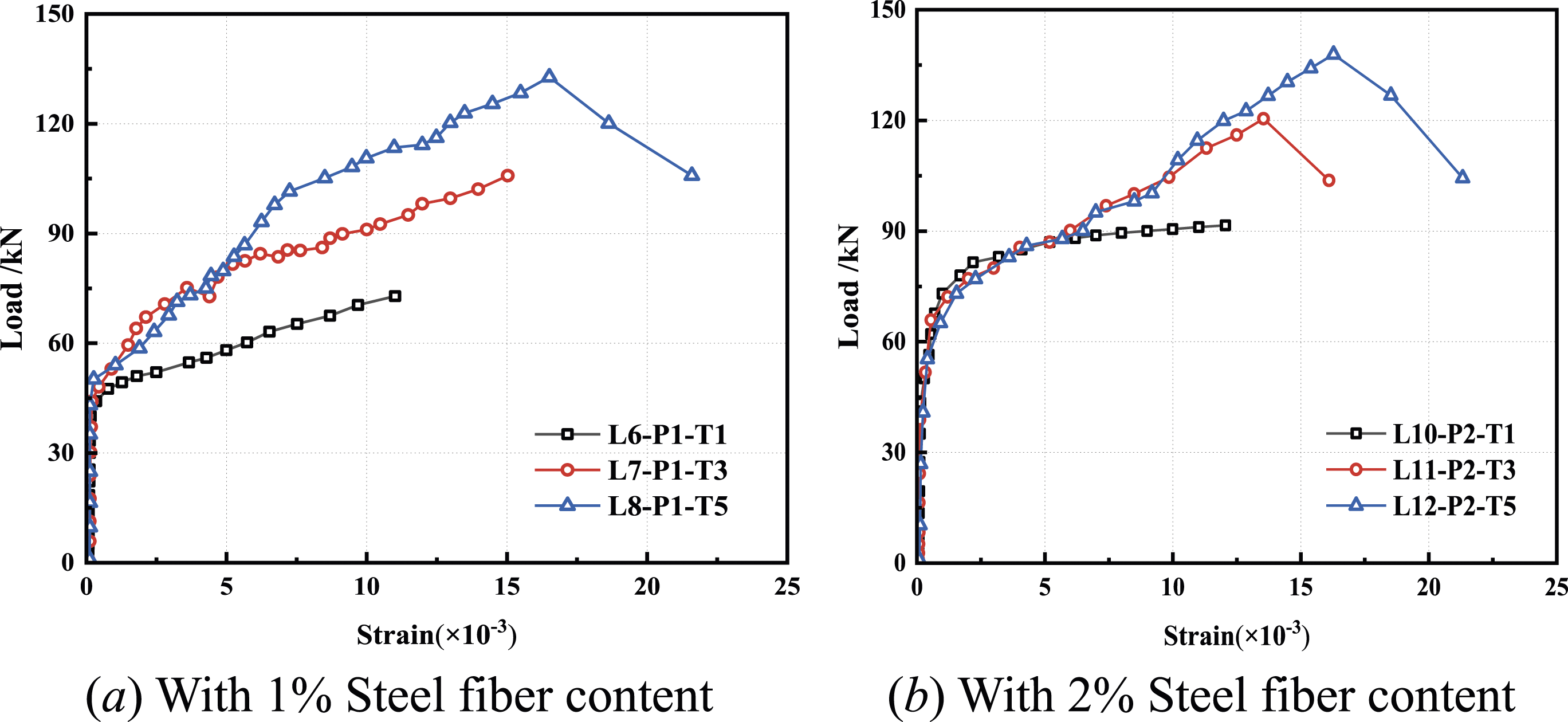
Calculation method
During the design of the flexural ultimate limit states for traditional reinforced concrete beams, the flexural contribution of concrete is commonly neglected, with the entire tensile strength being supported by the steel reinforcement. Contrasting with the traditional reinforced concrete beam, the contribution of UHPC in tension must be taken into account during the bending process prior to cracking, owing to the uniqueness attributed to the steel fibers incorporated within UHPC.16,33 Therefore, the traditional calculation method for flexural bearing capacity of cross-sections cannot be directly applied to UHPC. Based on the strain responses observed during the test, the plane section assumption is still valid in the FRP grid-reinforced UHPC I-beam, and the strain on the cross-section exhibits a linear distribution along the height. Meanwhile, assuming that there is no relative slippage between the FRP grid and UHPC, and that the strains within both materials are equivalent at same positions. The strain distribution across the I-shape beam cross-section remains uniform and linear.
The stress–strain diagram of the test beam at the cracking stage is shown in Figure 10. Since the compression zone is still in the elastic stage when the load reaches the cracking load, researchers often assume the stress in the compression zone to be triangular. Due to the bridging effect of steel fibers in UHPC, the stress near the bottom of the tension zone is arcuate, while the UHPC in other tension areas remains in an elastic state. So the complex tensile stress distribution of UHPC in the tension zone is approximated as a rectangular stress profile. The magnitude of the tension stress is represented by kf
t
, where f
t
denotes the tensile strength of UHPC, and k functions as a coefficient for accounting for the reduction in stress due to uniform distribution. Peng et al. pointed out that the value of k is related to the section height and steel fiber length,
34
and the following formula can be used Stress–strain diagram of the cross-section at the cracking stage: (a) Cross-section; (b)Strain distribution; (c)Stress distribution; (d)Equivalent rectangular stress distribution.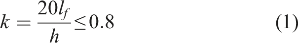
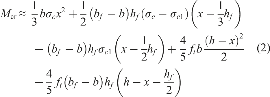
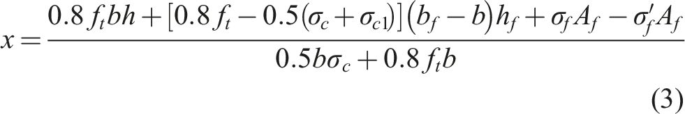
As to the ultimate strength, the cross section stress and strain distribution of the UHPC beam is shown in Figure 11. The UHPC at the compression zone surface reaches the compressive strength f
c
, and the triangular distribution pattern is considered the bridging effect of the FRP grid in the compression zone. The tension zone of the UHPC beam increases with the neutral axis moving up. Different from the cracking load calculation method, there are two cases for the position of the neutral axis in the flange and the web of the section. Stress–strain diagram of the cross-section at ultimate state: (a) Cross-section; (b) Strain distribution; (c) Stress distribution; (d) Equivalent rectangular stress distribution.
when the neutral axis in the flange of the section, the flexural bearing capacity of the section can be obtained with the following formula
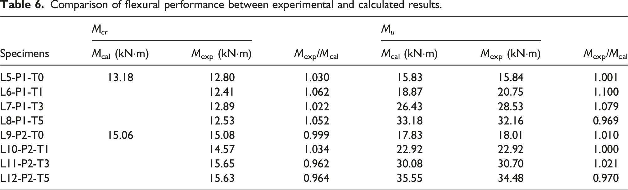
when the neutral axis in the web of the section, the flexural bearing capacity of the section can be obtained with the following formula The comparison between the calculated and experimental strength is shown in Table 6. It can be seen that for the cracking load and the flexural bearing capacity, the ratio between of experimental and calculated values ranges from 0.962 to 1.079. This is because the influence of the FRP grids are ignored during the cracking calculation process, and a simplified stress–strain distribution model is adopted when calculating the ultimate load. Overall, the error between the proposed simplified calculation method and the experimental results is acceptable for design applications, indicating that the proposed calculation method is effective.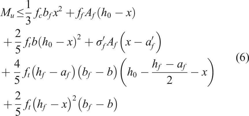

Comparison of flexural performance between experimental and calculated results.
Conclusions
In this paper, 12 FRP grid-reinforced UHPC I-beams were constructed, and the effects of steel fiber content (0%, 1%, and 2%) and the thickness of the FRP grid (0 mm, 1 mm, 3 mm, and 5 mm) on the flexural behavior of the I-beam were investigated. Four-point bending tests are applied to observe the failure modes, load-deflection curves, and strain responses with the aim to better adapt the assumptions to a simplified calculation method. Based on the above test, the following conclusions are drawn: (1) The FRP grid thickness inside the bottom flange can significantly improve the failure mode of FRP grid-reinforced UHPC I-beams. For the beam containing the FRP grid thickness less than 1 mm, the UHPC of the test beam will experience brittle fracture under ultimate loading conditions. It is available to increase the FRP grid thickness to provide tension strength for the beam. (2) The steel fiber content can effectively inhibit beam cracking during loading processing. The cracking load increases as the steel fiber content rises from 0% to 2%. However, the influence of steel fiber content on the ultimate load bearing capacity and failure mode of the beams is limited. The ultimate load bearing of the test beams with 2% steel fiber content is approximately 8% higher than that of the test beams with 1% steel fiber content. (3) Through strain analysis, it is observed that steel fiber contents and FRP grid thickness contribute to the improvement of the overall performance of the test beams and exhibit a more uniform distribution of section strains. Moreover, until to the cracking stage, there is no noticeable change in the tensile strain of the FRP grids as the applied load increases. (4) Based on the stress and strain distribution characteristics of the UHPC beam, a simplified calculation method for cracking loading and flexural bearing capacity is proposed. The calculated results are in agreement with the experimental results, which are acceptable for design applications.
Footnotes
Declaration of conflicting interests
The author(s) declared no potential conflicts of interest with respect to the research, authorship, and/or publication of this article.
Funding
The author(s) disclosed receipt of the following financial support for the research, authorship, and/or publication of this article: This work was supported by the Natural Science Foundation of Zhejiang Province (Y21E080011, LY20E080030) and the Wenzhou Municipal Basic Scientific Research Project (G20210026).
Data availability statement
Data sharing not applicable to this article as no datasets were generated or analyzed during the current study.