
Abstract
Running-specific prostheses (RSPs) allow amputees to run competitively and recreationally, offering stability, flexibility, and energy return. Despite advancements, RSP can still improve in materials and manufacturing. This study investigated the mechanical behavior of running-specific prosthesis (RSP) manufactured with a composite of carbon fiber and matrices of thermoplastic polyurethane (TPU) or polylactic acid (PLA). The research objectives were to experimentally determine the most suitable matrix (TPU or PLA) according to mechanical behavior and for the selected matrix to compute the mechanical response for using 8, 10, and 12 carbon fiber layers and a 6, 8, and 10 mm matrix thickness. The matrices were 3D printed and the carbon fiber layers were incorporated by a hand lay-up process. The applied load corresponded to a 60 kg user. Experimental measurements identified that the TPU matrix presents low stiffness compared to the PLA matrix. Numerical analysis indicated a delamination failure in the RSP with 8 layers, whereas with 10 and 12 layers, no failure was observed. No evidence of failure was exhibited for the TPU matrix. Because of its compression capacity, load resistance, and the absence of damage, the TPU is suitable for its use in the manufacturing of RSP.
Introduction
People who have had amputations of lower limbs are limited to their physical activities. This sedentary lifestyle can contribute to weight gain and obesity, which can lead to other health problems like diabetes and high blood pressure, among others. The disuse of certain muscle groups, due to the lack of physical activity, can lead to muscle atrophy, reducing human body mobility. Due to these factors, amputees may face mental health issues such as depression and anxiety.1,2 An option to replace the loss of lower limbs is running-specific prosthesis (RSP), which can reintegrate amputees into physical activities.
Prosthetic sports feet serve for different sports activities, and according to Poonsiri et al., 3 the performance of prosthetic sports feet in any sport is the most important characteristic for the users. In running sports, an RSP contributes to improving the running performance through enhancing step frequency, ground-contact and kinetics. An RSP functions like a spring, in which the compression depends on the level of the stiffness. The RSP is compressed during both the initial contact between the heel and the ground and the mid-stance stages, and then uncompressed during takeoff.4–6 The energy stored during compression is released, converting into forward propulsion for the runner. As a result, the amputee requires less effort to achieve a faster running gait, almost identical to a biological leg. 7 According to8,9 the magnitude of both stored and returned mechanical energy is inversely proportional to the prosthesis stiffness and depends on the magnitude and orientation of the force applied to the leg, therefore, a RSP with lower stiffness will store more energy. Considering both the stiffness and the resistance to compression, 10 it is assumed that the greater the compression, the greater the forward propulsion of the user.
Several investigations have been carried out to understand the behavior of RSP stiffness. Beck et al. 11 conducted research on the evaluation of the performance of commercial RSP. They tested four different models and evaluated their mechanical properties. They found that for the case of C-shaped RSP, when the user is running at 3 and 6 m/s, the peak of the reaction forces occurs at angles of 15.1 and 10°, respectively, and the load is 2.5 and 2.7 times the body weight of the RSP user. Also, the study concluded that when RSP users change prosthetics, adjustments in height and sagittal plane alignment cause changes in stiffness, which impact the performance of the RSP. Beck et al. investigated the effects of stiffness and height of different RSP models on the metabolic cost of running. 12 They conducted tests on five individuals with bilateral transtibial amputations. They found that stiffness and the RSP shape or model influence the metabolic cost of running, but not the height. The effect of the angle of alignment of a J-shaped RSP was studied by Groothuis and Houdijk to identify its effect on the stiffness and the gait pattern during running. 13 They conducted the tests under step frequency imposed condition and free condition at alignment angles of 0, 5, 10, and 15°. For both step frequency imposed and free condition, their results show that when the alignment angle increases, the RSP stiffness decreases. The RSP users require gait adaptation because the actual RSP stiffness is dependent on the alignment angle during running. Beck et al. 14 studied the effect of running speed, height, and prosthetic stiffness on the biomechanics of athletes with bilateral transtibial amputations. In a set of trials, they tested running speed ranging from 3 to 9 m/s, with increments of 1 m/s. Their conclusion suggests that stiffness, rather than height, has a greater impact on distance running performance compared to sprinting performance. Prosthetic stiffness had a mitigating effect on biomechanics during faster running, but height had no impact.
Composite materials are widely used in the fabrication of RSP, with carbon fiber being the most used material. The selection of carbon fiber is primarily due to its potential to store and release energy during a running sprint.15–17 Additionally, the use of carbon fiber increases flexural strength, which leads to a stiffness reduction. 18 Ismail et al. 15 evaluated the mechanical properties of carbon matrix composites for a RSP. They tested carbon fiber composites on matrices of four resins: epoxy bakelite, casting resin, PMMA (polymethyl methacrylate) Orthocryl, and polyester. Their findings showed that carbon fiber composites with Orthocryl PMMA matrix exhibited superior mechanical properties for RSP, including high bending stress, the highest stress, and the lowest impact energy. Sehar et al. 19 investigated the effect of the number of layers on the mechanical strength of carbon fiber composites for prosthetic applications. The authors carried out tensile tests to evaluate the effect of the number of layers on the carbon fiber specimens according to the ASTM D3039 standard. They applied the hand lay-up method to manufacture the specimens. These authors concluded that the manufacturing process is effective in the construction of the prostheses and also an increase of the mechanical strength was observed when more carbon fiber layers were used. In Ref. 20, 20 a new design of laminated-type prosthetic foot was proposed. They used rubber as the matrix material to improve the bending of the prosthesis. The authors concluded that the design performance is like the commercial LP Vari-flex model. Besides, 20 other authors have tested different types of polymer matrix materials in laminated composites as well as various manufacturing methods.20–23 These modifications had been made to design prostheses that are durable, functional and lightweight.24–26 The thermoplastic polyurethane (TPU) is a polymer whose properties include high mechanical resistance and rubber-like flexibility, making it ideal for RSP designs. 27
Another challenge to solve is reducing the cost of commercial prostheses because the high cost makes them unaffordable for most potential users. To address this issue, it is necessary to investigate and evaluate new composite alternatives and propose more cost-effective manufacturing processes.28,29
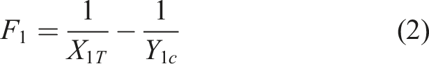
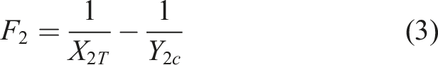
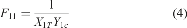
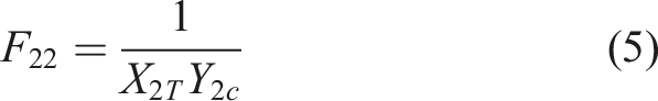
In this work, a simple manufacturing process is proposed to construct a carbon fiber polymer matrix composite RSP. Two different polymers were compared experimentally to determine the best RSP performance based on stiffness and mechanical strength: polylactic acid (PLA) and (TPU). Matrices were manufactured by fused deposition modeling and the composite structure was by hand lay-up process. The materials were chosen because they can be processed using a standard 3D printer. The properties of both materials are different, with TPU being more flexible than PLA. However, results show how these properties were modified due to the addition of carbon fiber. After identifying the best material, the effect of increasing both the number of layers and the matrix thickness was analyzed using the finite element method. The calculated responses from the numerical study include the Tsai-Wu failure index,
Experimental and numerical methodology
This work was carried out in four stages: prosthesis construction, mechanical tests, hyperelastic modeling, and finite element computations. During the first stage, using the hand lay-up method, two RSP laminated composites were manufactured. The layers of carbon fiber and matrices of thermoplastic polyurethane (TPU) or polylactic acid (PLA) made up the composite material. In the second stage, measurements were performed to evaluate Workflow stages of experimental and numerical studies.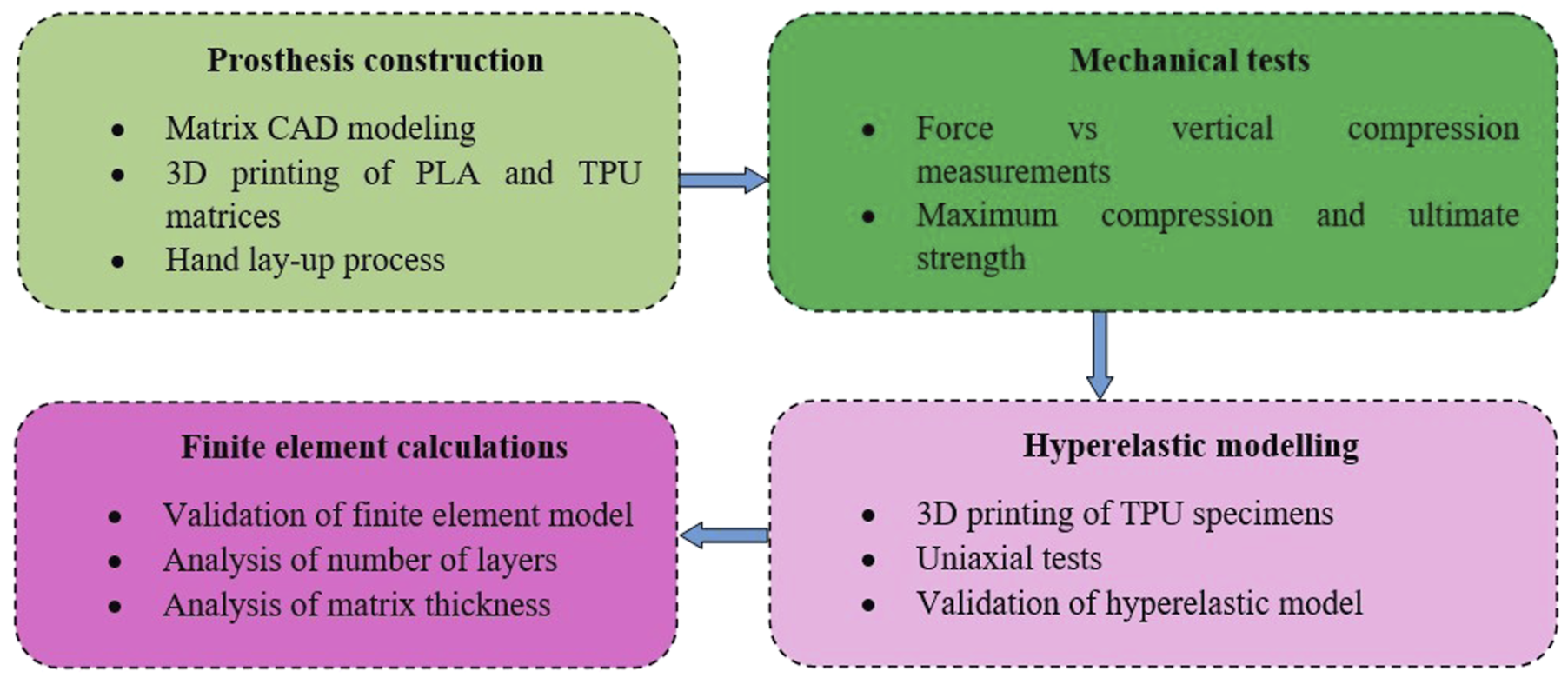
Prosthesis construction
The shape of the RSP was based on the Össur Flex-Run Junior Model. To approximate the curved contour, a side view image was imported into CAD software using the prosthesis height as a reference length. The contour was traced over the image in the sketch to replicate its shape and dimensions. The height of the matrix, RSP matrix dimensions with values: 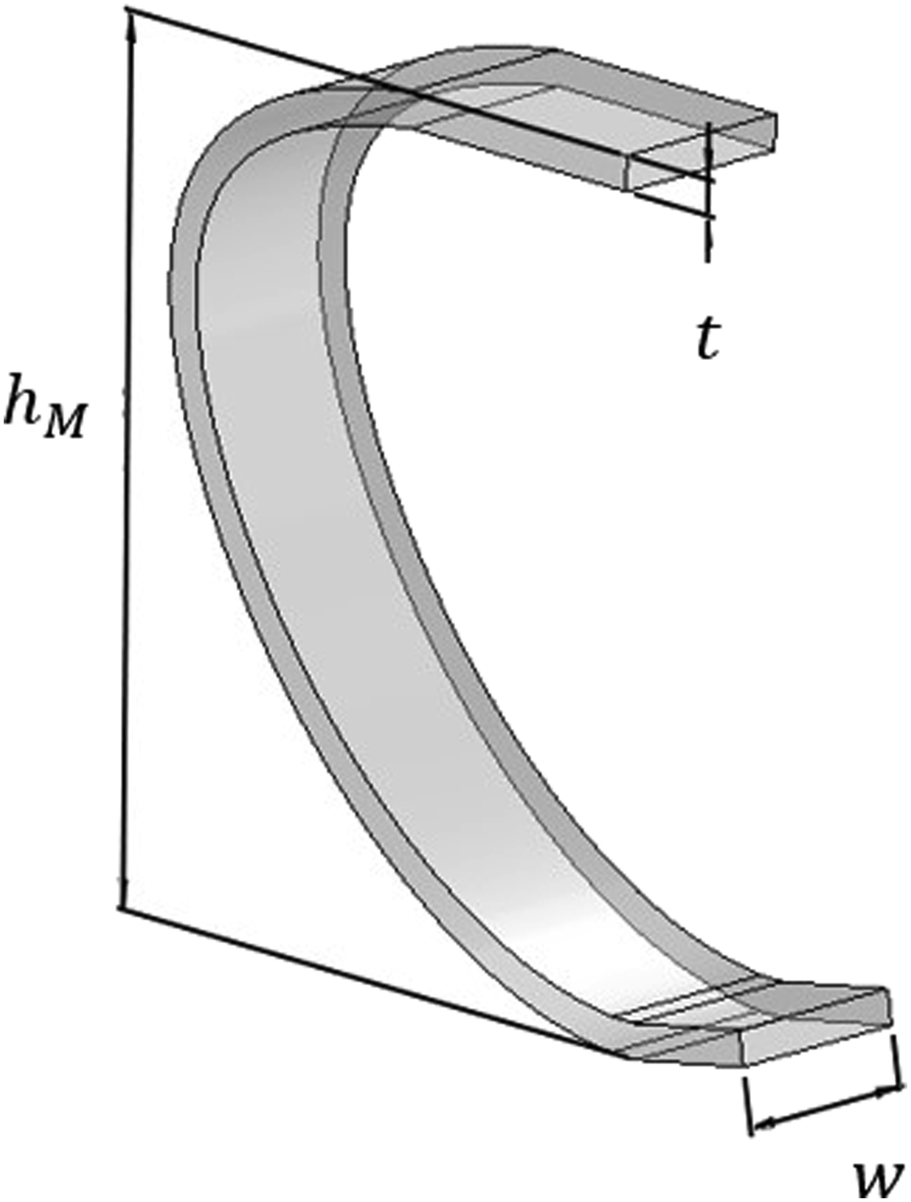
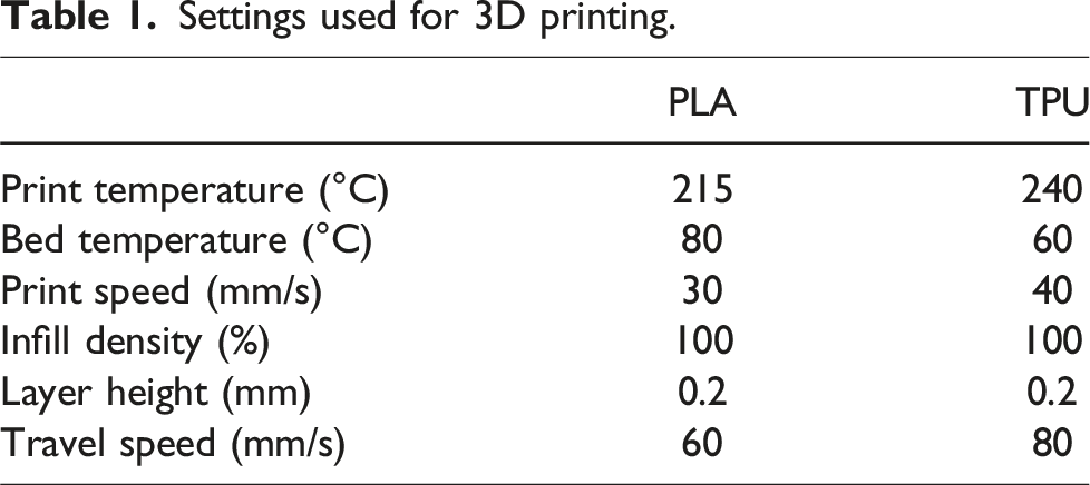
Settings used for 3D printing.
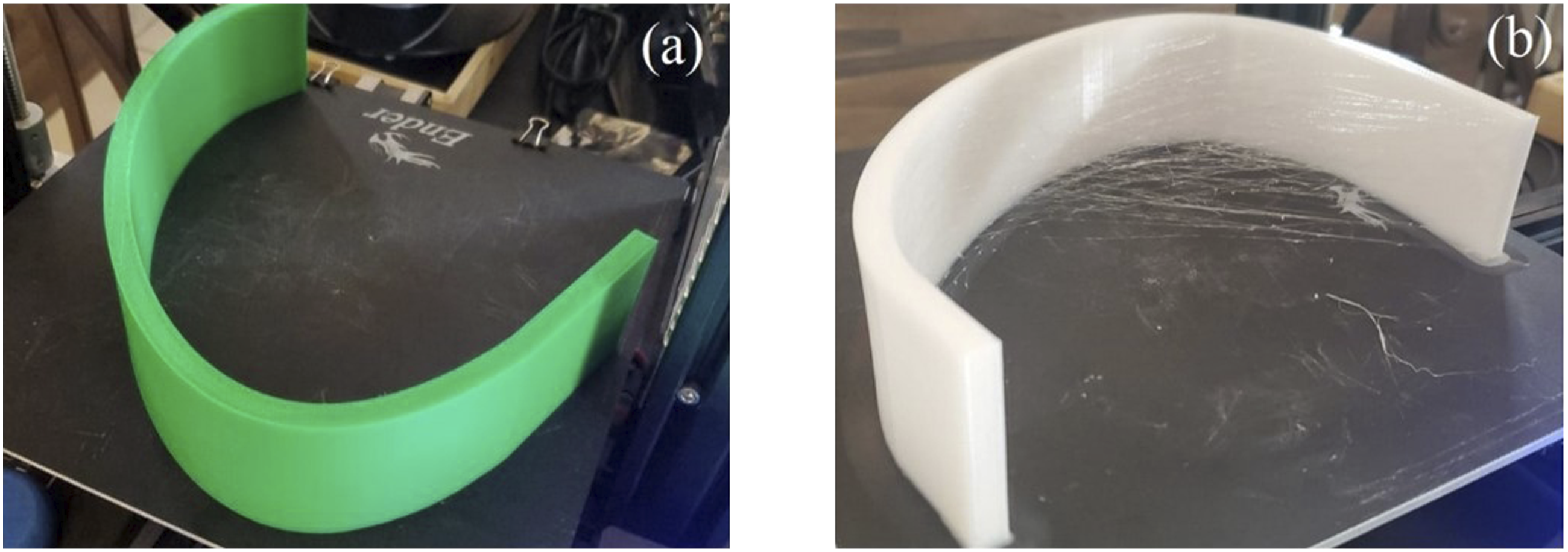
3D printed RSP matrices. (a) PLA filament and (b) TPU filament.
The next step was the composite manufacturing using the hand lay-up, involving manual application of fiber layers to form the composite structure.
30
,
31
The fiber used was a bi-directional carbon fiber fabric with a 2 × 2 twill patterns, 6k tow with a thickness of 0.43 mm from Composite Envisions™. A resin mixture was prepared as a blend of Thin Epoxy Resin 1159A™ and Epoxy Hardener Slow Cure 1160B™ at a 2:1 ratio. The surface of the RSP matrix was smoothly sanded and then cleaned to ensure a proper adhesion. Using a brush, the whole internal RSP surface was coated with the resin mixture after which the first layer of carbon fiber was laid on one side, and this process was done in alternating steps, applying the resin mixture followed by a layer of carbon fiber, continuing this sequence until 10 layers of carbon fiber were completed. The curing time was 36 hours at room temperature. The same process was repeated on the external side of the RSP. After the curing time of the remaining side, the excess fiber was trimmed. By following this procedure, the two composite RSPs (PLA or TPU matrix) were manufactured. The total height RSP manufactured using the hand lay-up method. (a) PLA and (b) TPU.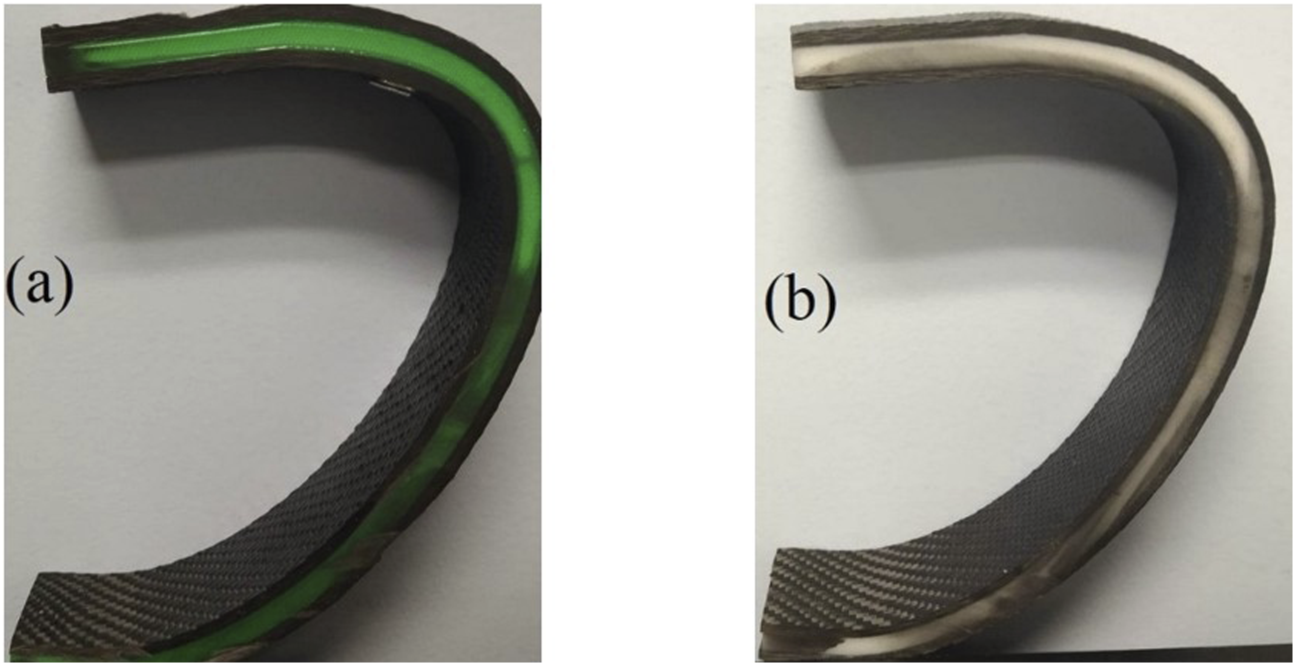
Mechanical test
The mechanical tests were conducted to determine which of the two materials exhibits better performance, in terms of Compression testing of the RSP model.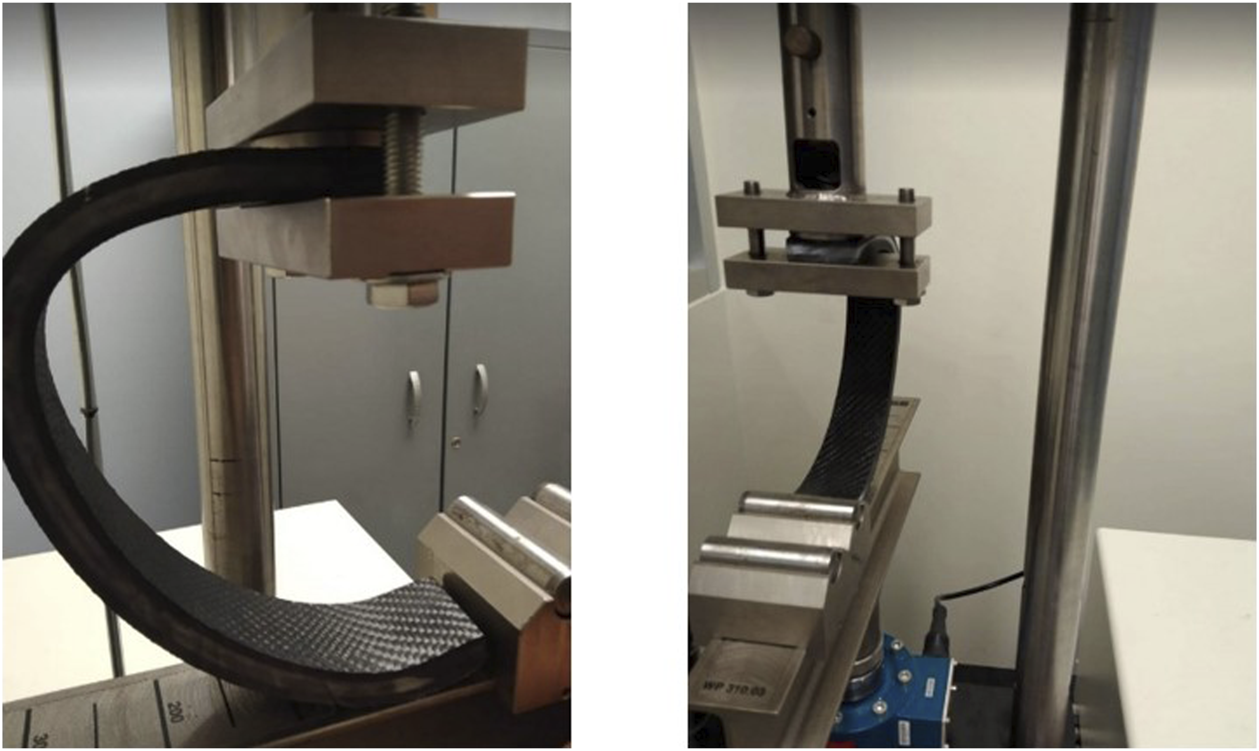
Hyperelastic modeling
Because TPU is considered a hyperelastic material,32,33 before conducting FEM simulations, it was necessary to model its elastic response to ensure an accurate simulation capable of predicting the behavior of TPU. For this purpose, in the third stage, uniaxial tests were carried out to obtain stress-strain data, which were subsequently used to define the hyperelastic model that best approximates the experimental results. The specimen dimensions,
33
shown in Figure 6, were defined based on the DIN EN ISO 527-1 type 1BA standard. Specimen dimensions: 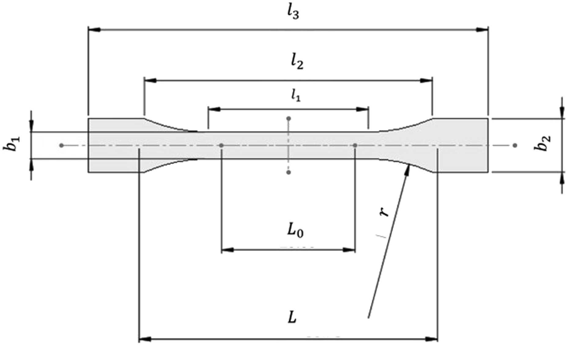
The five specimens, shown in Figure 7(a), were printed using the same settings employed in the printing of the TPU matrix (see Table 1). The measurements were conducted in accordance with the DIN EN ISO 527-1 standard. The testing machine was a Sintec 20/G with a load capacity of 100 kN. The specimen mounted during the test can be observed in Figure 7(b). Uniaxial tests based on DIN EN ISO 527-1 standard. (a) Specimens and (b) specimen during testing.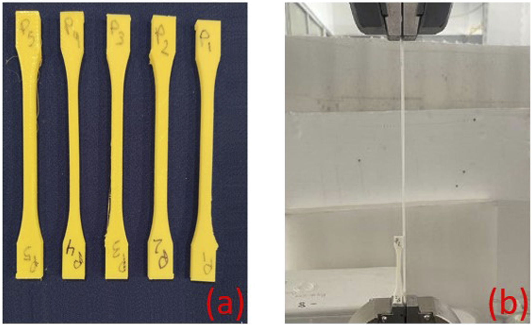
Finite element calculations
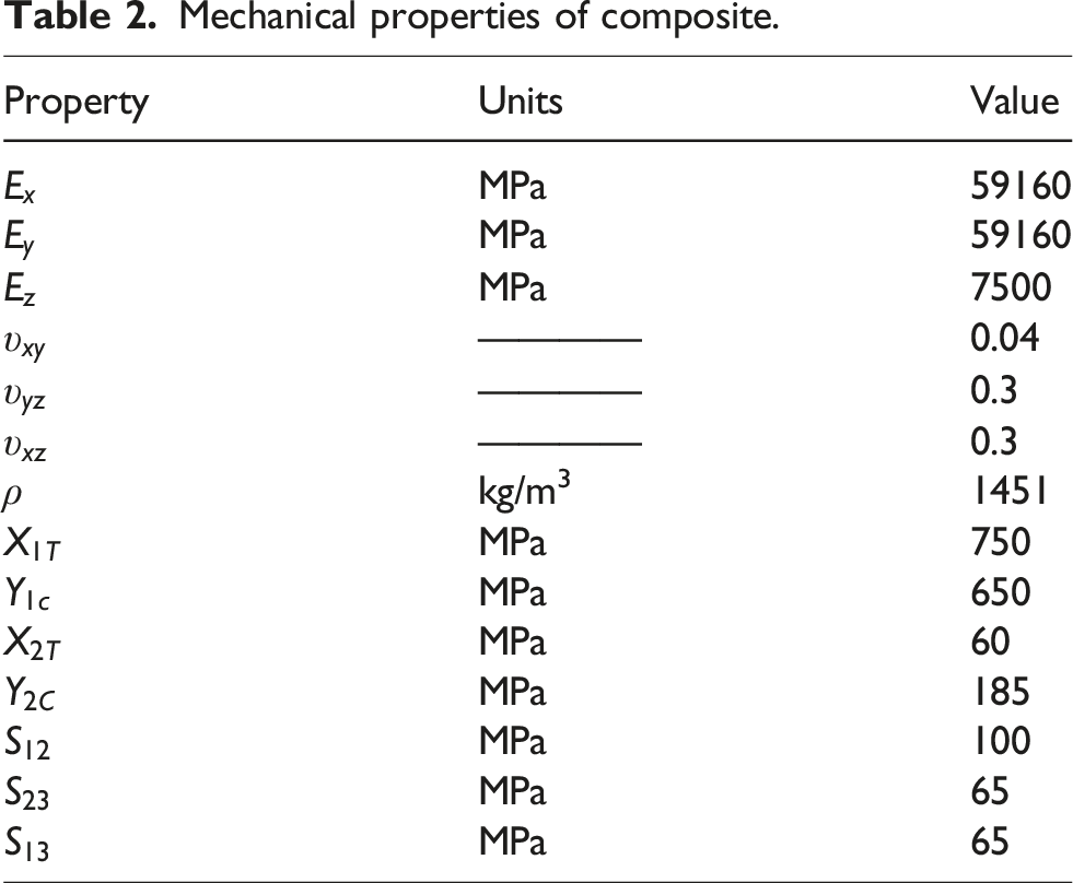
The effects of the number of carbon fiber layers and matrix thickness were investigated in the fourth stage using FEM. Three different matrix thicknesses were analyzed (8, 10, and 12 mm) and for each thickness, the number of layers per side varied from 8, 10, and 12 layers. Three domains were modeled, two of them correspond to the external and internal fiber layers, and the third domain corresponds to the hyperelastic material matrix (Figure 8). The TPU has a density of 1040 kg/m3 and the rest of its mechanical properties were defined based on the selection of the hyperelastic model, whereas the mechanical properties of the composite are presented in Table 2. Geometrical model of RSP. Mechanical properties of composite.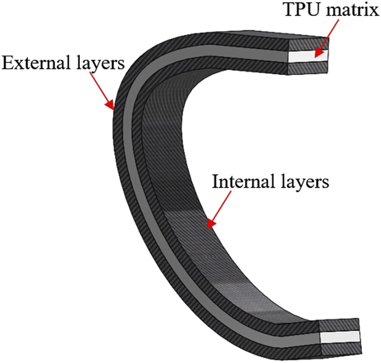
The load was applied at 600 and 1500 N to address standing and dynamic conditions, respectively, considering that the weight of prospective users is 60 kg.
34
The load was applied at two angles (Figure 9). According to Beck,
11
15° and 10° correspond to a running speed of 3 and 6 m/s, respectively, for a C-shape RSP design. The domain was fixed at the lower surface of the base, which was in contact with the ground. Force and constraints applied to the RSP.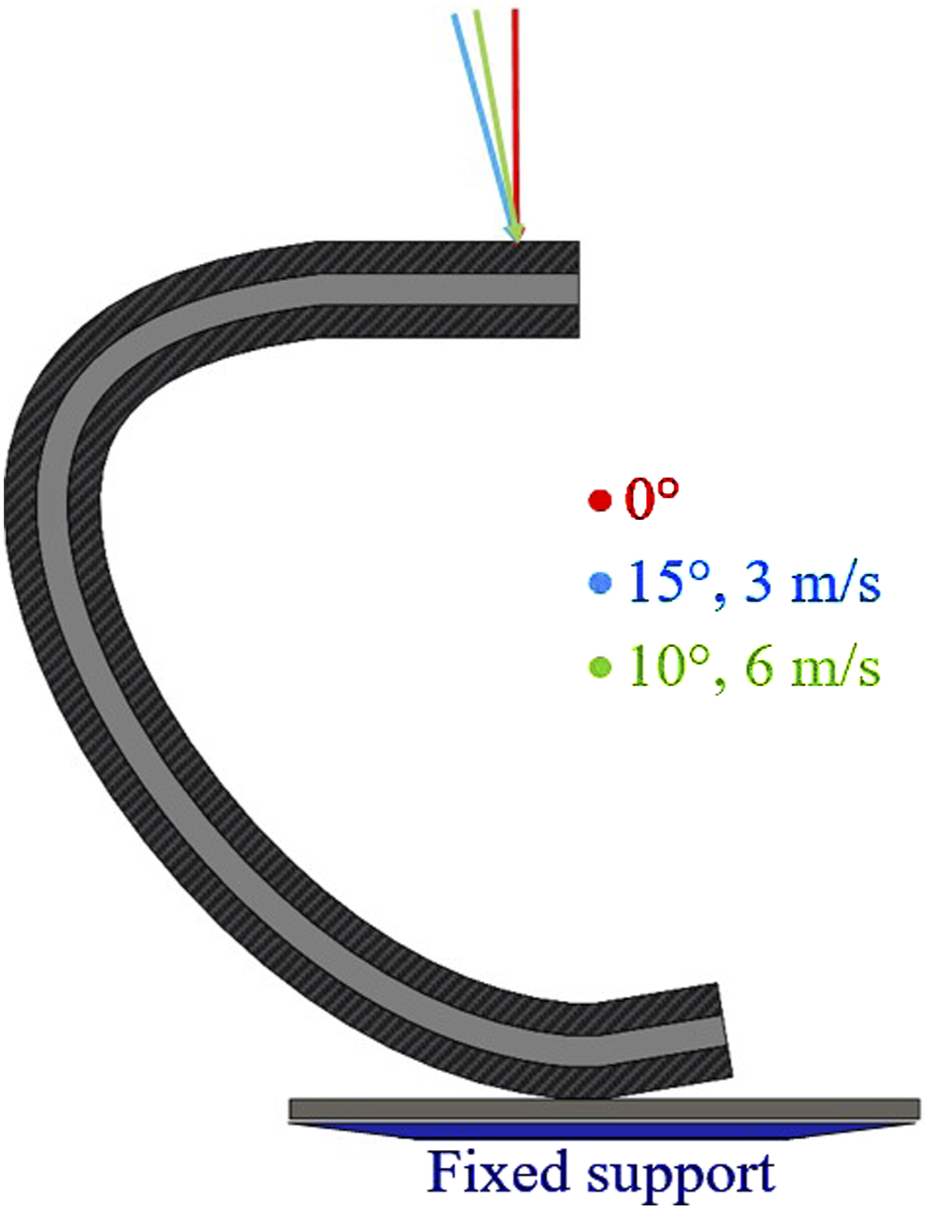
To determine the effects of the number of layers and matrix thickness, three major results were obtained from FEM calculations: the first one was the stresses in the TPU matrix, 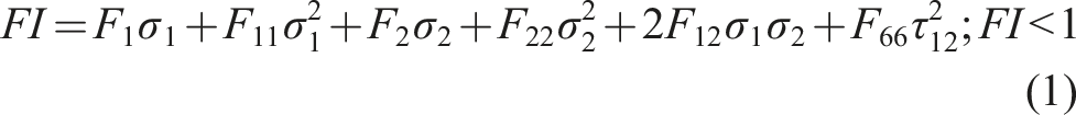
The finite element model was constructed using elements of a size of 4 mm based on a convergence study where Meshed model and mesh convergence study.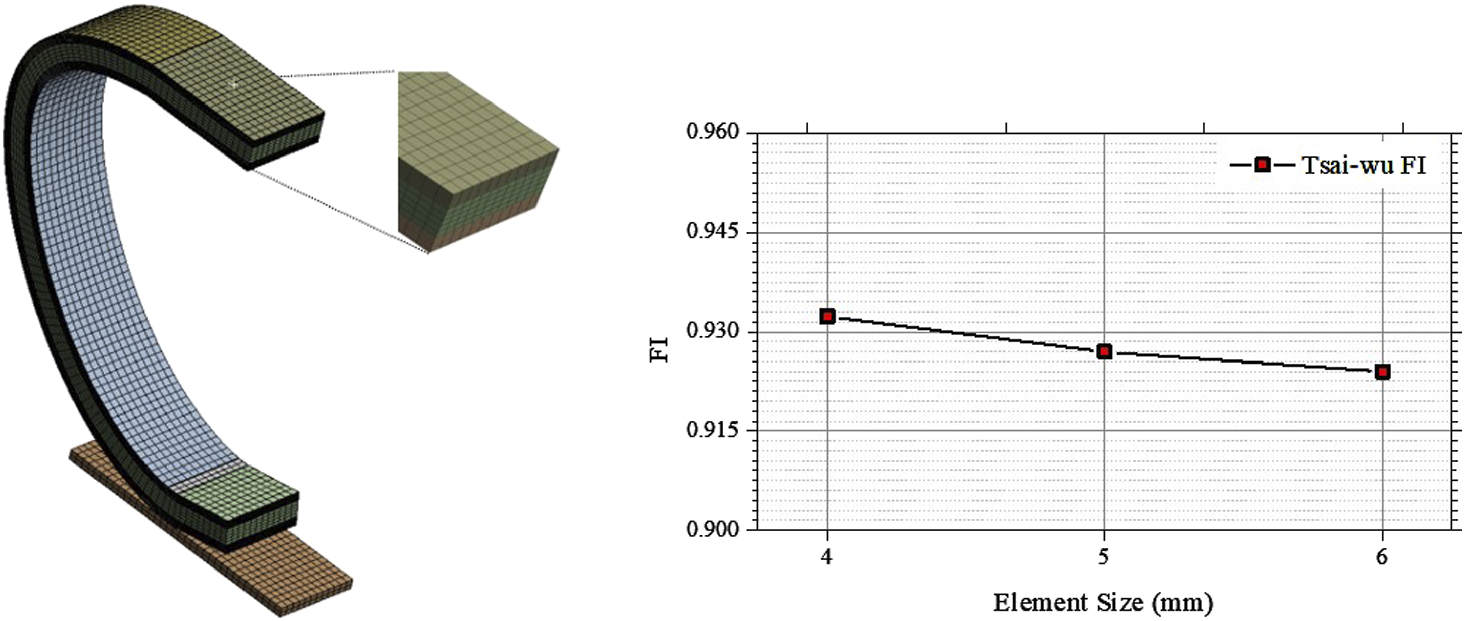
In addition to the validation of the hyperelastic material behavior, simulations were performed to validate the full model, ranging from loads lower than standing conditions to dynamic conditions. The load was applied at 0°, and the rest of the FEM settings were the same as previously described.
Results
Experimental results
The two manufactured RSPs were tested to determine whether the material, PLA or TPU, presents a better trade-off between higher compression and its mechanical resistance. In Figure 11, the Comparison of TPU and PLA stiffness.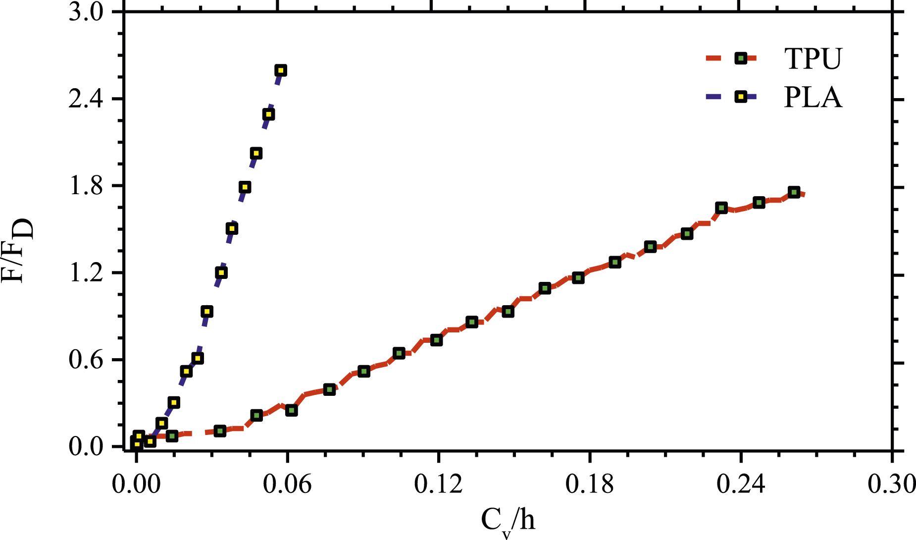
To determine the strength of the RSP, the force was increased until failure occurred in both models. The TPU model failed under a load of around 2.5 kN and its displacement was 61 mm, whereas the PLA model was subjected to a load of 7 kN and achieved a displacement of 20 mm. A key finding from the experimental measurements was that the PLA material can withstand a higher load; however, the TPU displacement was three times greater. In both models, the crack took place in the internal layers of the prosthesis, as can be observed in Figure 12. The failure occurred due to delamination, extending along the entire side of the prosthesis in the case of PLA. The delamination in the case of the TPU matrix occurred in a portion of the cross-sectional area of the internal side. The failure mechanics for this delamination was interlaminar shear failure because as FEM computations indicated, there was high stress in such areas. In both cases, the matrix did not suffer any damage. Failure of RSP designs. (a) PLA and (b) TPU.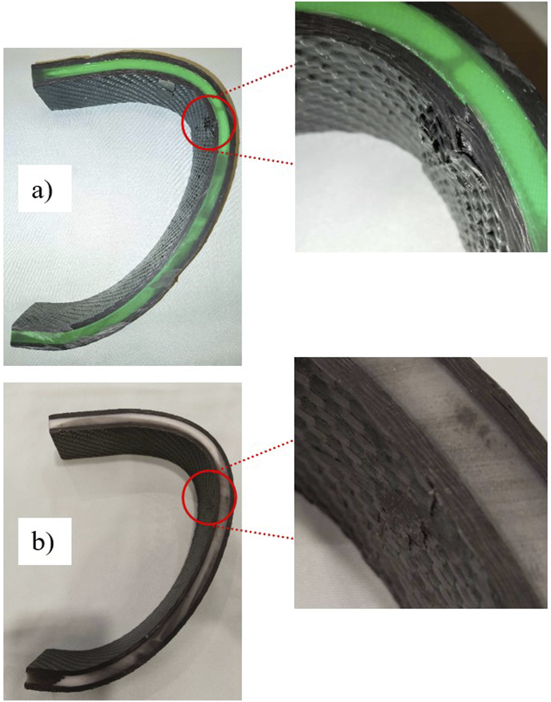
Numerical results and discussion
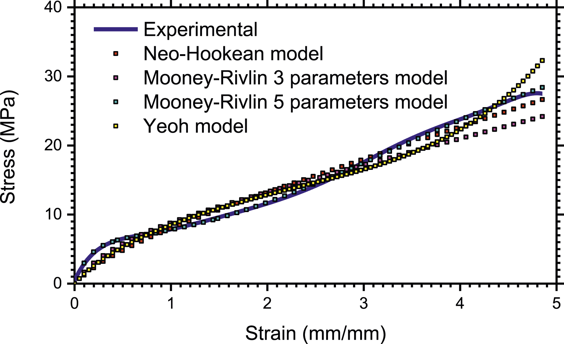
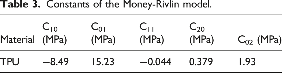
The effects of the number of layers and the thickness of the matrix were evaluated using finite element calculations. Considering the properties of TPU, the first step was to select the hyperelastic model that best approximates its behavior. The comparison of the models and the result from the uniaxial experimental test is shown in Figure 13. During the experimental test, the material TPU exhibited a strain greater than 400% and stresses lower than 30 MPa. The hyperelastic model that best approximates the TPU behavior is the Mooney-Rivlin 5 parameters model because, as can be observed in Figure 13, it presented good agreement with experimental data. Considering that the prostheses deformation magnitudes are lower, this model is the best option to compute Comparison between uniaxial test results and hyperelastic models. Constants of the Money-Rivlin model.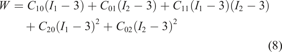
For the composite RSP with TPU matrix, the comparison of experimental and numerical vertical compression due to the force applied is presented in Figure 14 using the normalized vertical compression and the normalized applied force. The composite RSP is intended to be used between the range of standing conditions, Comparison of experimental and finite element results.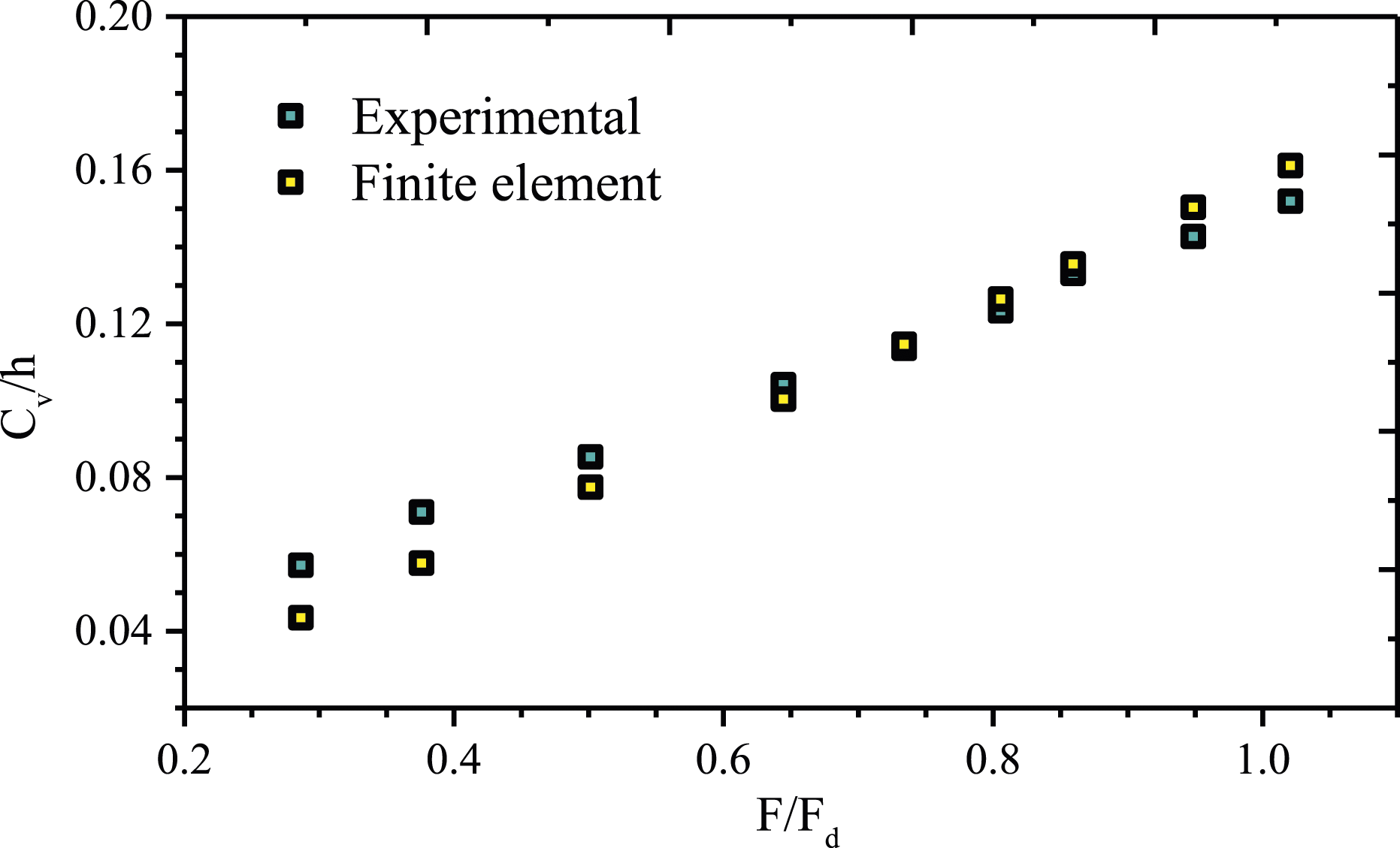
The results of Comparison of stress, Cv/h, and FI varying thickness and number of layers. Top row: standing conditions; middle row: 3 m/s; bottom row: 6 m/s.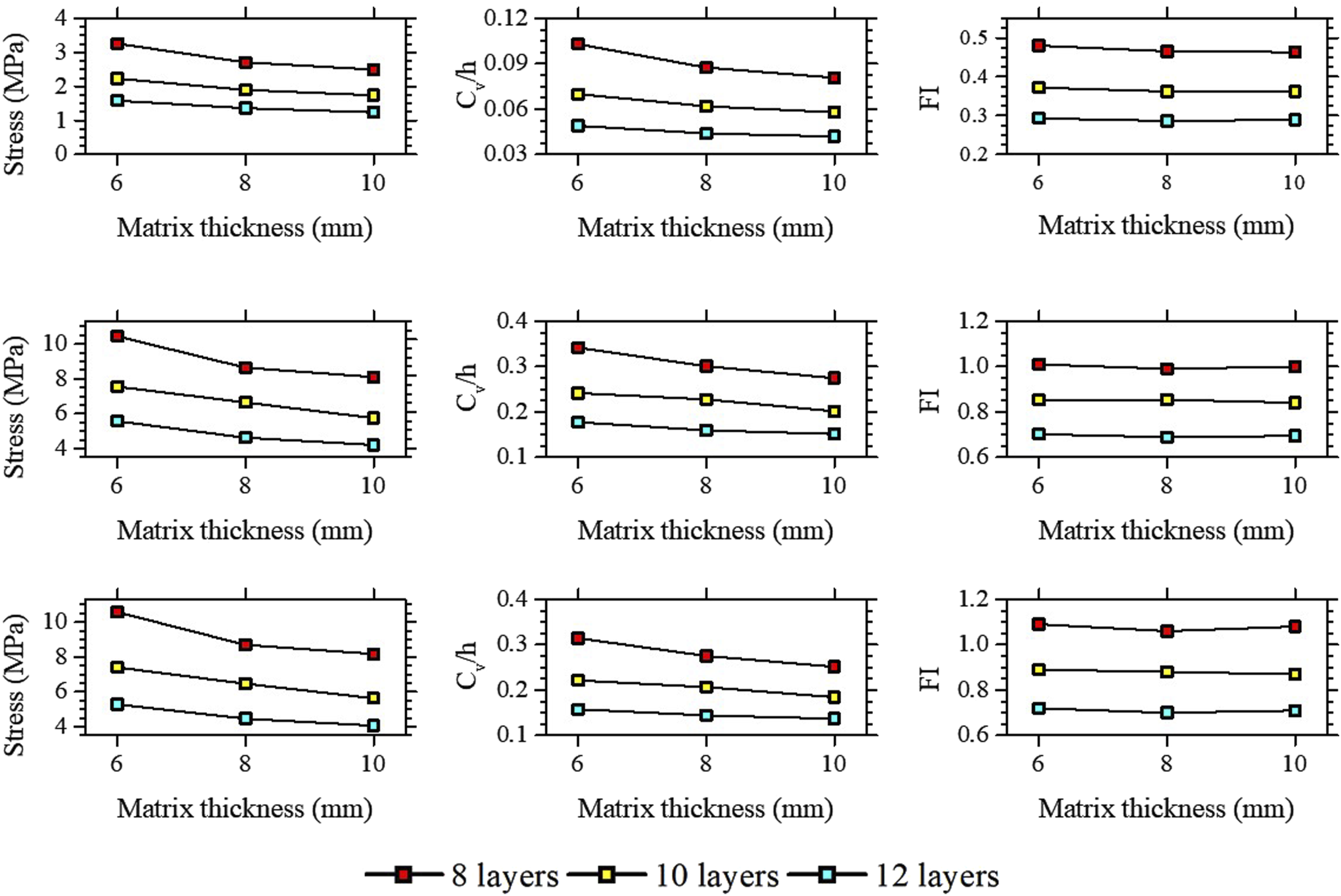
The RSP design with 10 layers and 8 mm of thickness was selected to present the contours of FI, Finite element contours of: (a) 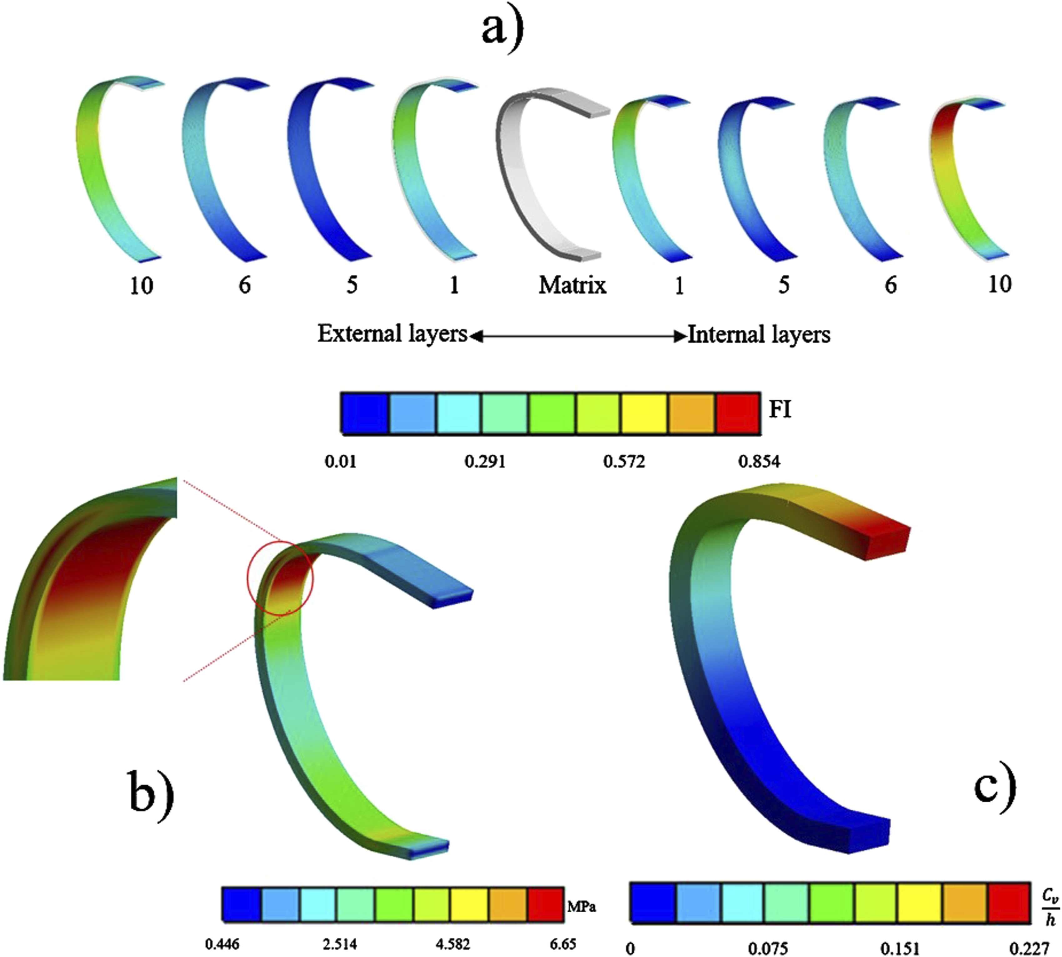
Conclusions
In this paper, RSPs were compared experimentally to evaluate their mechanical behavior. The RSPs were made with composite materials including a matrix of PLA and TPU. The best RSP design was analyzed using FEM calculations to identify the influence of matrix thickness and the number of carbon fiber layers. The carbon fiber TPU matrix composite RSP demonstrated a good performance due to its low stiffness, while also withstanding 1.8 times the force before the failure occurred. The failure mechanism occurred due to delamination on the internal side of the prosthesis. The Mooney-Rivlin 5 parameters model was the best to fit the TPU behavior. Increasing the carbon fiber layers will reduce the FI, but also increase the stiffness of the RSP. Designs with more than 8 layers are highly recommended for adolescents weighing 60 kg. No signs of matrix damage were observed in any of the studied cases. Both
Footnotes
Author contributions
Omar Dávalos: conceptualization, investigation, methodology, formal analysis, validation, and writing—original draft. J.C. Garcia: methodology, data curation, formal analysis, validation, and writing—review and editing. Clemente Mirafuentes, C. M.: investigation, formal analysis, validation, and writing—original draft.
Declaration of conflicting interests
The author(s) declared no potential conflicts of interest with respect to the research, authorship, and/or publication of this article.
Funding
The author(s) received no financial support for the research, authorship, and/or publication of this article.
Data availability statement
Data will be made available on request.