
Abstract
This study employs machine learning (ML) algorithms to predict the tensile strength of 3D printed continuous carbon fiber reinforced polyether ether ketone (CF/PEEK) thermoplastic composites, addressing the critical need for rapid and cost-effective material qualification in additive manufacturing. A total of 120 samples were fabricated using fused deposition modeling (FDM), with systematic variations in key printing parameters, including printing path design (unidirectional and orthogonal printing), printing speed (270–600 mm/min), and nozzle temperature (375–410°C). The experimental tensile strength of the composites ranged from 310 MPa to 976 MPa. A Gradient Boosted Decision Tree (GBDT) algorithm was utilized to establish correlations between printing parameters and tensile properties, achieving a comprehensive determination coefficient exceeding 0.8, demonstrating high predictive accuracy. Cross-validation and grid search methods were employed to optimize model parameters, resulting in robust generalization capabilities across training, testing, and validation datasets. Through prediction and validation using ML models, the optimal parameter combination was identified as follows: unidirectional printing, a printing speed of 330 mm/min, and a nozzle temperature of 380°C. The study reveals that the printing path has the most significant impact on tensile strength (relative importance: 0.8), followed by printing speed (0.15) and nozzle temperature (0.05). This research provides an efficient data-driven approach to predict and optimize the mechanical properties of 3D printed composites, aligning with industrial demands for sustainable, lightweight materials in aerospace, automotive, and energy sectors, and offering a scalable solution to accelerate the development and application of 3D printed thermoplastic composites.
Keywords
Introduction
Additive manufacturing, particularly fused deposition modeling (FDM), has emerged as a transformative technology for producing complex, customized parts with reduced material waste and processing steps. This technology has found applications across various industries, including aerospace, marine, wind energy, and automotive sectors. 1 Recent advances in FDM have enabled the fabrication of high-performance thermoplastic composites by integrating continuous fiber reinforcement, addressing critical limitations of unreinforced polymers such as low stiffness and strength. Notably, FDM-based 3D printing of continuous fiber reinforced composites allows precise control over fiber orientation and layer-by-layer deposition, enabling tailored mechanical properties for specific loading conditions.
Carbon fiber reinforced polyether ether ketone (CF/PEEK) thermoplastic composites have garnered significant attention among FDM materials due to their high strength, stiffness, corrosion resistance, and recyclability, aligning with sustainable development goals. Since Stepashkin et al. 2 successfully developed a 3D printer for continuous CF/PEEK composites, considerable efforts have been made to explore the effects of printing parameters on the mechanical properties of these 3D printed continuous fiber reinforced composites. The extrusion-based 3D printing process for continuous fiber reinforced composites involves several critical steps. First, a pre-impregnated filament consisting of carbon fibers embedded in a PEEK matrix is fed into the printer nozzle through a precision-driven extrusion system. The filament is heated in the nozzle to the temperature range of 375–410°C, where the PEEK matrix transitions from a solid to a molten state, facilitating controlled extrusion. Simultaneously, the motion of the print head follows a predefined path (unidirectional or orthogonal) to deposit the molten composite layer-by-layer onto the build platform. The fiber orientation within each layer is determined by the printing path, which directly influences the mechanical anisotropy of the final part. After deposition, rapid cooling (assisted by a heated bed at 140°C and forced airflow) solidifies the molten polymer, forming an interlayer bond. This process repeats until the complete part geometry is achieved, with precise control over parameters such as printing speed (270–600 mm/min), nozzle temperature, and path design being essential to minimize defects (e.g., voids, delamination) and optimize mechanical performance. For continuous carbon fiber reinforced PEEK composites, the maximum practical fiber weight fraction typically ranges from 40% to 60% by weight, as higher fractions compromise extrudability due to increased viscosity and fiber entanglement risks. Pros: Superior specific strength, thermal resistance, and recyclability compared to unreinforced polymers. Cons: High equipment costs, limited build sizes, and stringent parameter sensitivity requiring optimization.
Printing parameters critically determine the mechanical properties of 3D printed composites through their influence on polymer crystallization, fiber impregnation, and interlayer bonding. Printing temperature (typically 375–410°C for PEEK) governs polymer chain mobility and cross-linking: temperatures below 375°C may cause incomplete matrix melting and poor fiber wetting, while excessive heat (>410°C) risks polymer degradation and void formation. Recent advances in machine learning for additive manufacturing have been comprehensively reviewed by Khan et al., 3 who highlighted the application of ML in defect detection, process optimization, and performance prediction for lattice structures, providing valuable context for our ML-based predictive modeling of CF/PEEK composites. Chen et al. 4 systematically examined how nozzle diameter, edge width, and layer thickness interact with temperature to optimize interfacial bonding, identifying 390–400°C as the critical range for balanced crystallinity and fiber impregnation. Vatandaş et al. 5 demonstrated that infrared heating during printing could mitigate interfacial defects caused by suboptimal temperature control, proposing a gradient temperature profile (375–400°C) to enhance layer adhesion. Rodzeń et al. 6 developed a low-cost printer with a heated chamber to maintain stable polymer flow at elevated temperatures, achieving consistent quality across 380–410°C. Printing speed (270–600 mm/min) directly affects the cooling rate and crystallinity of the PEEK matrix-slower speeds promote better layer adhesion but increase thermal accumulation, whereas higher speeds may lead to insufficient interlayer bonding due to rapid solidification.4,6,10 Luo et al. 7 identified 300–400 mm/min as the optimal speed range to balance fiber impregnation and cooling time, minimizing void formation. Qin et al. 8 optimized sizing treatments for prepreg filaments to enhance fiber-matrix adhesion at high speeds (500–600 mm/min), while Ding et al. 9 recommended speed reduction (270–350 mm/min) for thin-walled parts to improve surface finish and dimensional accuracy. Layer height (commonly 0.1–0.3 mm) influences interfacial bonding quality and void formation, with thinner layers improving surface finish but requiring longer printing times. Li et al. 10 demonstrated that 0.1 mm layer height reduced interlayer voids by 25% compared to 0.3 mm, though at the cost of increased printing time. Parker et al. 11 showed that layer height below 0.2 mm significantly enhanced fiber distribution uniformity, critical for isotropic property development. Among process parameters, printing path design (unidirectional vs orthogonal) plays a pivotal role in determining mechanical anisotropy. Unidirectional paths align fibers along the primary load direction, maximizing tensile strength but introducing directional dependence, while orthogonal paths distribute fibers across multiple axes, enhancing isotropic properties at the cost of reduced peak strength. Chen et al. 4 quantified 15–20% higher tensile strength for unidirectional patterns and proposed hybrid path designs to balance strength and toughness. Vatandaş et al. 5 introduced gradient path transitions to mitigate stress concentrations at layer interfaces, while Li et al. 10 recommended unidirectional paths for high-load applications and orthogonal paths for complex geometries requiring isotropic behavior.
Recent advancements in the field of gradient temperature control by Li et al., 10 printing parameter control and optimization include optimized curved fiber trajectories by Sugiyama et al., 12 variable speed printing strategy for in situ impregnation 3D printing by Quan et al., 13 a sequentially coupled optimization of structural topology and fiber orientation by Zhang et al., 14 an aligned fiber deposition method by Zhang et al., 15 an orthogonal-element solid orthotropic material topology optimization by Yang et al., 16 a novel 3D printed extruder with in situ traction force monitoring by Zhang et al., 17 a high-degree-of-freedom 3D printing method by Kumekawa et al., 18 a multiscale concurrent design approach by Huang et al., 19 a concurrent optimization method for structural topology and fiber paths by Wang et al., 20 and a mathematical model for analyzing warpage deformation mechanisms by Shen et al.. 21
To further investigate the constitutive characteristics and failure mechanisms of 3D printed composites, several models have been developed. Hou et al. 22 formulated a constitutive model for 3D printed composites. Garzon-Hernandez et al. 23 developed a viscoelastic-viscoplastic constitutive model. Thiago Assis Dutra et al. 24 introduced a reverse identification method for assessing fiber, matrix, and interface bonding strengths. Somireddy and Czekanski 25 employed a computational homogenization method. Zhang et al. 26 proposed a performance-driven concept for guiding carbon fiber placement paths. Despite these advancements, establishing clear correlations between 3D printing process parameters, structural characteristics, and the mechanical performance of composites remains challenging. Traditional experimental methods are time-consuming and costly, while theoretical modeling and finite element analysis (FEA) often struggle with the complex microstructures of 3D printed composites.
Data-driven prediction methods leveraging machine learning (ML) algorithms have shown promise in efficiently predicting macroscopic stress-strain responses of composite samples.27,28 Cai et al. 29 used ML for parameter optimization in 3D printed natural fiber reinforced composites. Ferdousi et al. 30 developed an image-driven ML approach for investigating mechanical properties of 3D printed lightweight hybrid composites. Polyzos et al. 31 introduced a method for creating accurate microscale finite element models of 3D printed composites using neural network algorithms. Chen et al. 32 employed exponential and sigmoidal functions to fit relationships between continuous fiber volume and mechanical properties. However, there remains a significant research gap in developing high-efficiency and robust correlations and predictions between mechanical properties and printing parameters of 3D printed continuous fiber reinforced thermoplastic composites using ML.
To address this gap, this study first investigates the effects of key printing parameters (path design, speed, and nozzle temperature) on the tensile properties of 3D printed CF/PEEK composites through experimental testing. Second, a Gradient Boosted Decision Tree (GBDT) model for predicting tensile strength based on printing parameters is developed, and its predictive performance and generalization capabilities across different datasets are evaluated. Finally, the relative importance of various printing parameters on the tensile strength of composites is analyzed. By achieving these objectives, this research seeks to provide a robust and efficient tool for predicting and optimizing mechanical properties of 3D printed CF/PEEK composites. This approach has the potential to significantly accelerate the development and application of these advanced materials across various industries, reducing the need for extensive experimental testing and complex numerical simulations.
This study is structured as follows: we first detail the sample preparation, printing parameters, and mechanical testing procedures for CF/PEEK composites; second, we establish the GBDT prediction model, evaluate its performance, and analyze parameter importance; Third, we discuss the effects of printing parameters on mechanical properties and compare with prior studies; finally, we conclude the key findings and outline future research directions.
Preparation and mechanical tests of 3D printed thermoplastic composites
Sample preparation of 3D printed CF/PEEK thermoplastic composites
The workflow of Fused Deposition Modeling (FDM) is outlined as follows: continuous printing wire is heated to a molten state and extruded from the nozzle according to a predetermined path established by the system.1,3,8 Subsequently, it is molded and solidified on the working platform. Upon completing one layer, the nozzle ascends to print the next layer on the solidified base. This iterative process continues until the final part is completed. 1 Commercially available 3D printing filaments for high-performance applications primarily include carbon fiber reinforced PEEK (CF/PEEK), nylon (PA), and polylactic acid (PLA). In this study, PEEK is selected for continuous fiber printing due to its classification as a high-performance engineering plastic, recognized for its exceptional mechanical properties and thermal stability. PEEK is capable of withstanding continuous operational temperature up to 250°C and can tolerate short-term exposure to temperature as high as 300°C.1–5 Even under such elevated temperature conditions, PEEK retains its superior hardness and strength. Moreover, PEEK exhibits outstanding chemical resistance, making it resilient against the erosion caused by most solvents and chemicals, along with good hydrolysis resistance in high-temperature and high-pressure environments.2–6
This research employs a FDM 3D printer specifically designed for continuous carbon fiber reinforced PEEK composites, as illustrated in Figure 1. A customized hybrid printing system integrates commercially available components with in-house modifications. The core mechanical structure uses a modified Anycubic Kossel Linear Plus frame, while key functional modules like the nozzle assembly, heating system, and temperature controller are entirely reengineered. The nozzle has a dual channel architecture with an inner diameter of 0.4 mm, a 1.5 mm thick alumina ceramic thermal barrier layer, and active cooling by a 24V DC fan (40 CFM). Thermal simulations validated a steady-state temperature gradient <±2°C across the nozzle body. The heating system includes a 24V 70 W cartridge heater, a TT-K-30 type K thermocouple, and an STM32F407 microcontroller-based controller with optimized PID parameters (Proportional Gain = 3.2, Integral Gain = 0.65, Derivative Gain = 1.8) for a response time <1.2 s. The print volume is 300 mm × 300 mm × 300 mm, driven by NEMA 23 stepper motors with linear guides. FDM 3D printer for continuous carbon fiber reinforced PEEK composites.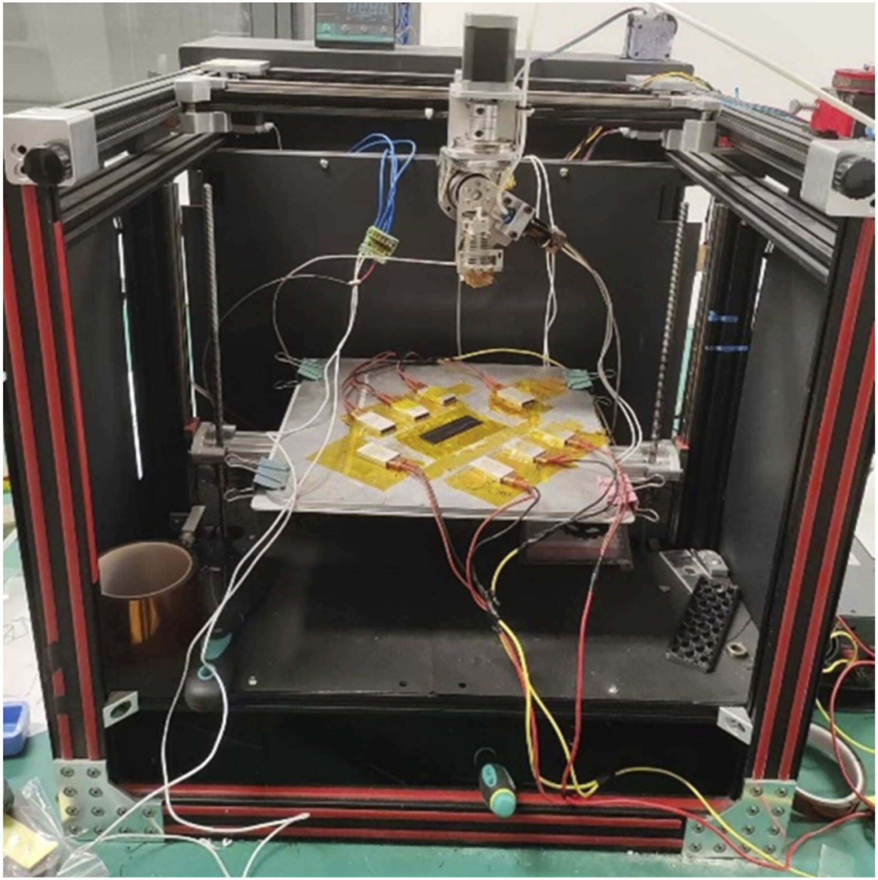
A software program written in C language is developed to configure various printing parameters for single plate samples. This software allows for the adjustment of critical parameters, including the printing path (the trajectory or direction followed by the print head when constructing objects), retraction compensation, fill spacing, printing speed, layer height, the number of layers, and initial XYZ coordinates. Upon completion of these configurations, the software will directly output the corresponding G-code.
When printing composites, various defects may arise due to the inherent properties of materials, the printing processes employed, and environmental conditions, all of which can adversely affect the performance and quality of the final product. 1 Common defects encountered in 3D printed composites include the following: (1) Warping, a prevalent issue particularly in FDM technology, often manifests on the outer surface of printed object due to uneven cooling and shrinkage of the material, resulting in deformation. (2) Delamination occurs when there is insufficient adhesion between printed layers, leading to layer debonding. This may stem from inappropriate printing parameters, such as excessive printing speed or inadequate temperature control, or insufficient bonding characteristics of materials. (3) Bloating refers to an increase in material volume due to absorption of liquids or gases; this is particularly pertinent if the printing material is sensitive to humidity. (4) Cracking involves the formation of internal fissures in the material, often arising during the printing process due to stress concentration or material defects. Such cracks can significantly diminish the load-bearing capacity and durability of the material. Beyond these defects, 3D printed composites may also exhibit issues such as voids, incomplete curing, and material inhomogeneity.
It is noteworthy that low layer height and spacing can result from fiber being overly compacted. Insufficient accumulation of fiber and resin per unit volume may induce stress deformation,10,18 where horizontal deformation is less likely to occur; the most prevalent deformation in this context is warping. In this study, the selected sample dimensions are 20 mm × 70 mm × 0.4 mm, with an optimized layer height of 0.1 mm and a layer spacing of 1.0 mm, printed in four layers, with the heated bed temperature set to 140°C. Key printing parameters include the printing speed, temperature, and path. The speed is adjusted from 270 to 600 mm/min, while the temperature varies from 375 to 410°C.3,4,7 Here, two kind of printing paths are selected including the unidirectional printing and orthogonal printing. In the unidirectional printing path, the print head prints along a single direction in each layer, and the printing path direction of each layer is the same. By comparison, the orthogonal printing is an alternating printing path where the print head prints alternately along two orthogonal directions in each layer. The chosen temperature range is justified by the melting point of PEEK, approximately 343°C, necessitating a printing temperature typically around 400°C to facilitate adequate material flow and crystallinity.2,4,7 Despite the requirement for elevated temperature to ensure the melting and flow of PEEK, caution is warranted as excessive temperature can lead to degradation of the material, thereby impairing printing quality and performance. Additionally, high temperature may cause the material to carbonize within the nozzle, leading to blockages, and excessive melting can compromise adhesion to the print bed, destabilizing the printed components. The G-code file is integrated into the real-time control software platform TwinCAT, and the nozzle temperature must be established before commencing the printing process. The preprocessing of 3D printing continuous CF/PEEK composites primarily involves material preparation and software configuration. The pre-impregnated carbon fiber/PEEK filaments must be dried at 120°C for 4–6 hours to remove moisture, ensuring optimal melt flow and interlayer adhesion. Software configuration includes defining printing parameters (path design, speed, temperature) and generating G-code for precise motion control. Post-processing focuses on improving mechanical performance and surface quality. Thermal annealing at 200–250°C for 2–4 hours enhances crystallinity and reduces residual stresses, while surface treatments like sanding or chemical smoothing address layer-line artifacts. These steps collectively ensure dimensional stability and performance consistency, addressing challenges such as warping and void formation during printing. Ultimately, a total of 120 samples are printed. Figure 2 illustrates the printing paths utilized in this study. 3D printed CF/PEEK composite samples by unidirectional and orthogonal printing paths.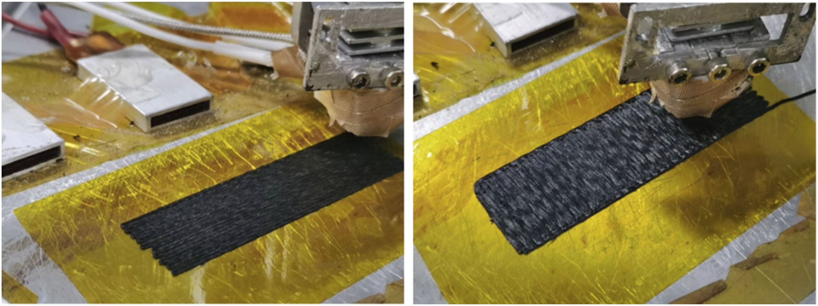
To mitigate the occurrence of warping, this study emphasizes modifications to the printing head, with enhancements primarily focusing on the feeding, shearing, melting, and cooling functions. (1) Feed Mechanism: Powered by a stepper motor, the driving wheel rotates, facilitating the movement of carbon fiber filament through a groove in the driven wheel towards the nozzle. (2) Cutting Mechanism: A four-bar linkage mechanism driven by a servo module allows for precise cutting of the composite fiber filaments. (3) Melting Mechanism: A heating rod affixed to a heating block heats the block, which in turn melts the resin within the carbon fiber, allowing for the extruded material to flow from the nozzle. (4) Cooling Mechanism: An electric fan directs airflow onto the sprayed fibers to expedite cooling.13,17
Prior to conducting tensile tests, reinforcing plates will be applied to the samples to enhance clamping stability and minimize stress concentration. These reinforcements are strategically placed at the clamping ends to increase contact area and promote uniform stress distribution, thus preventing non-representative failures that may arise from uneven contact or excessive localized stress. The reinforcing patches are composed of an 8100-type structural adhesive, recognized for its high bonding strength, which will ensure stability during the tensile testing process and prevent interruption due to adhesive failure. Moreover, this adhesive exhibits excellent wettability, allowing for complete penetration of the fibers, thereby forming a uniform bonding layer that enhances bonding quality.
Mechanical tests of 3D printed thermoplastic composites
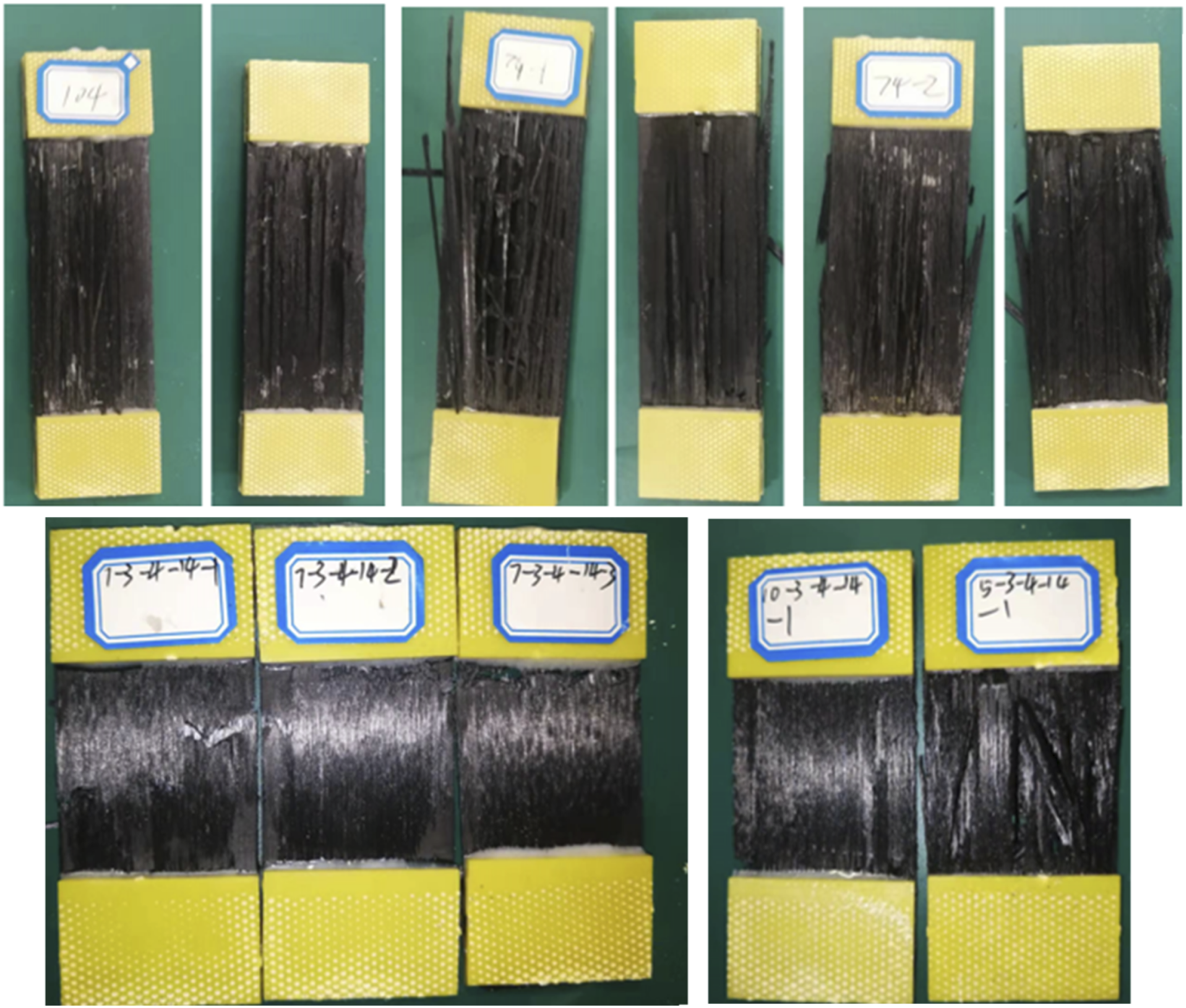
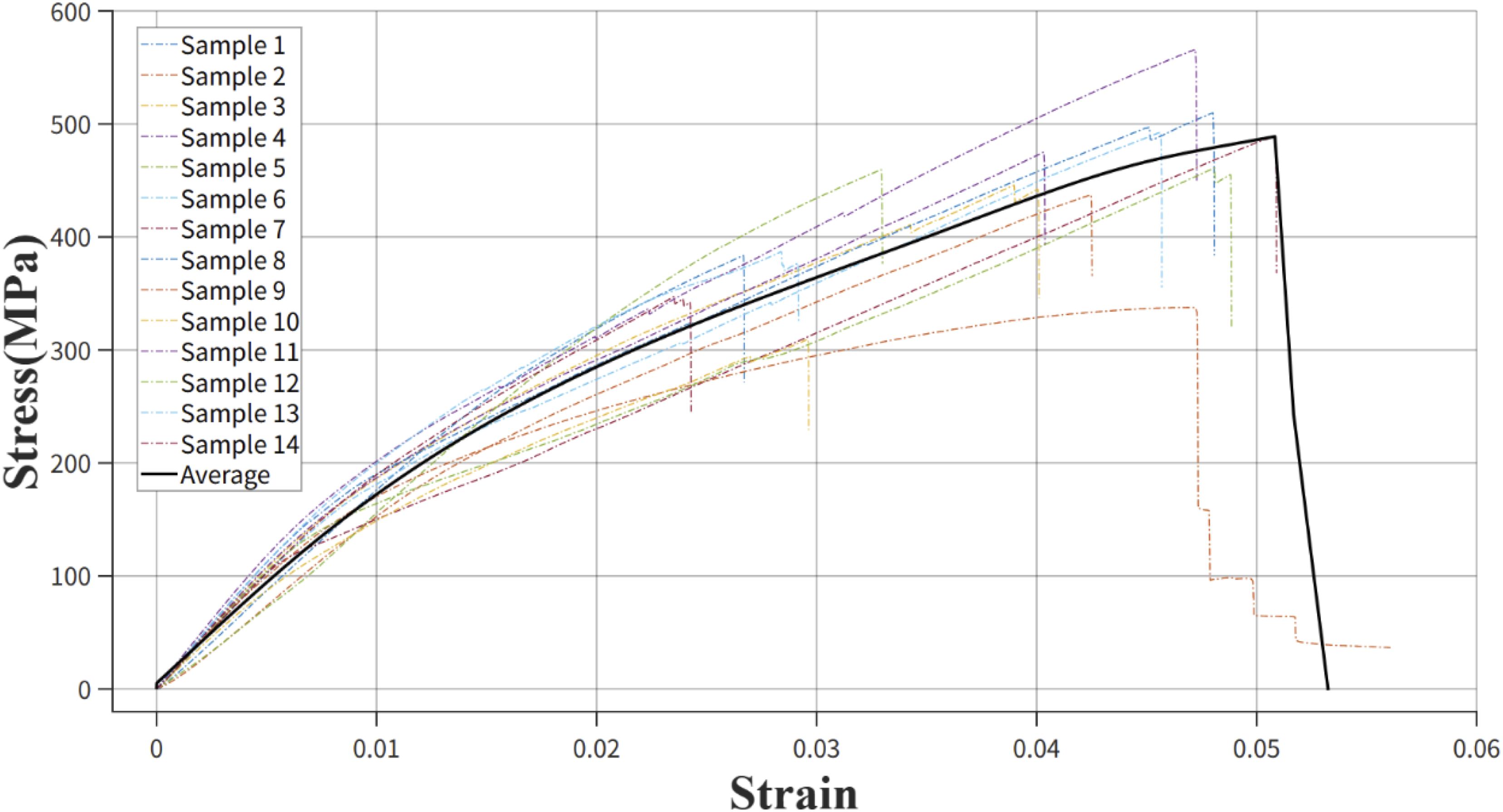
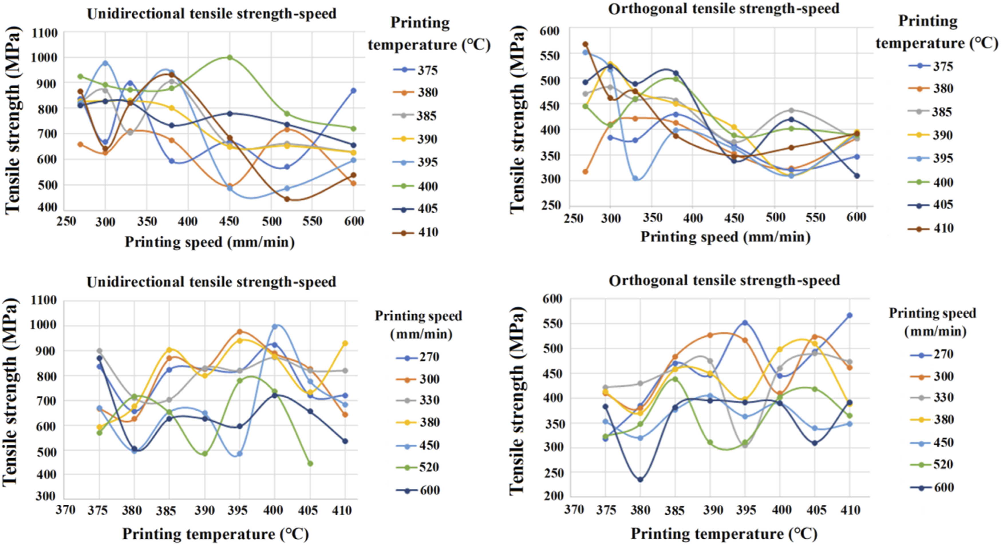
Figure 3 illustrates the tensile experiments conducted on the 3D printed CF/PEEK composites using a universal material testing machine. The tests refer to the ASTM D3039/D3039M-08 standard, “Standard Test Method for Tensile Properties of Polymer Matrix Composite Materials.” Figure 4 depicts the fractured samples and Figure 5 presents the tensile stress-strain curves for select samples. Figure 6 displays the relationships between the tensile strength and nozzle temperature, as well as the tensile strength and printing speed under both the unidirectional printing and orthogonal printing paths, facilitating preliminary analysis of the impact of these parameters on the tensile strength. The unidirectionally printing tensile strength-speed curve reveals that at a printing temperature of 380°C, the tensile strength initially increases and subsequently declines with increasing printing speed, peaking at 899 MPa at a speed of 330 mm/min. This indicates that at this specific temperature, a moderate printing speed enhances interfacial adhesion within the composite, thus improving the tensile strength.3,4,13 Conversely, increasing the printing speed beyond this point may prevent sufficient cooling and solidification time, adversely affecting interfacial bonding and reducing the tensile strength. The unidirectionally printing tensile strength-temperature curve shows that tensile strength rises with increasing printing temperature until reaching a peak, beyond which it declines. This suggests that an optimal temperature range exists for the melting and interfacial adhesion of the composite4,5,7; however, excessively high temperature can degrade material performance. For the orthogonally printing tensile strength-speed curve, the relationship between the tensile strength and printing speed is less pronounced compared to the unidirectional path, with the overall tensile strength being lower. This finding suggests that the orthogonal path may not be conducive to optimal interfacial adhesion or that the mechanical properties of composites are not fully realized in this configuration.10–16 Regarding the relationship between the orthogonally printing tensile strength and temperature, it is observed that the tensile strength increases with temperature, yet declines at elevated temperature (e.g., 405°C and above). This indicates the existence of an optimal printing temperature range, where the melting and flow characteristics of composites are most favorable for enhancing the mechanical properties of the printed samples. In conclusion, the tensile strength observed under the unidirectional printing path is generally superior to that of the orthogonal printing path, which may be attributed to enhanced interfacial adhesion and mechanical properties associated with the unidirectional path.8–15 Both the printing speed and temperature exhibit optimal ranges that maximize the tensile strength; improper printing speed may hinder adequate curing and interfacial adhesion, while extreme temperature, either high or low, can be detrimental to the performance of composite. Tele experiments of 3D printed CF/PEEK composites. The fractured 3D printed CF/PEEK composite sample. The tensile stress-strain curves of 3D printed CF/PEEK composite samples. The tensile strength-nozzle temperature curve and the tensile strength-printing speed by unidirectional and orthogonal printing paths.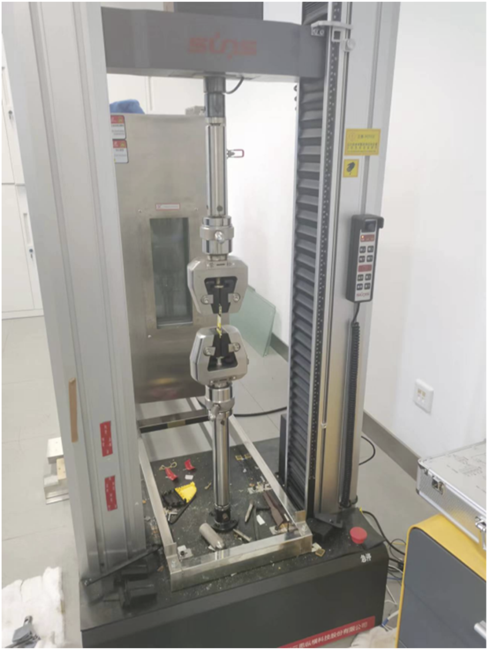
Vatandaş et al. 5 explored the combined effects of printing parameters, including path, temperature, and speed, on the mechanical performance of CF/PEEK composites, emphasizing that a consistent extrusion speed is vital to avoid defects such as voids or porosity within printed layers. Their findings indicate that strategic modifications to the printing path, such as adopting zigzag or concentric patterns, can enhance stress distribution and improve durability under dynamic loads. Qin et al. 6 demonstrated that well-prepared prepreg filaments exhibit enhanced interfacial bonding, which significantly contributes to the strength of printed parts. Similar to the present work, their research indicated that adjusting the pre-heating temperature of filaments can improve the flow characteristics of PEEK matrix, facilitating better fiber wetting. Additionally, Rodzeń et al. 6 illustrated that modifying extrusion temperature and optimizing the cooling rate of 3D printed CF/PEEK composites could substantially improve interfacial bonding. They also revealed that temperature control during cooling affects residual stresses within the layers, thus impacting the overall toughness of the printed components. Luo et al. 7 observed that elevated printing temperature enhances the matrix flow and impregnation of CF/PEEK composites, leading to superior interfacial bonding; however, they caution against excessive temperature that may degrade the matrix, consistent with the present findings. Finally, Li et al. 10 concluded that slower printing speed tends to enhance fiber alignment within the printed structure, thereby increasing the tensile strength and stiffness of CF/PEEK composites, while acknowledging a trade-off between speed and production efficiency.
Strength prediction model of 3D printed thermoplastic composites using gradient boosting decision tree (GBDT)
Establishment of strength prediction model using GBDT
The Gradient Boosting Decision Tree (GBDT) has emerged as a prominent ML algorithm, widely utilized across various domains due to its exceptional performance.27,28 GBDT is an ensemble learning technique that systematically trains decision trees in an iterative manner, effectively minimizing model errors and ultimately constructing a high-performance ensemble model. 33 In comparison to a standalone decision tree, GBDT consistently demonstrates superior predictive accuracy, particularly when addressing complex nonlinear relationships inherent in the data. This study employs the GBDT algorithm to predict the tensile properties of 3D printed CF/PEEK composites, thereby exploring its applicability in materials science.
The GBDT method was selected for three specific reasons: (1) Nonlinear relationship capture: The complex interactions between printing parameters (speed/temperature/path) and tensile strength in CF/PEEK composites exhibit significant nonlinearities and threshold effects (e.g., strength drop >12%/10 mm/min beyond 450 mm/min), which traditional linear models (e.g., response surface methodology) fail to model accurately. (2) Feature importance quantification: GBDT’s inherent ability to rank parameter importance (0.81 for path) directly addresses our research objective of identifying dominant control factors, whereas black-box models (e.g., neural networks) lack interpretability. (3) Data efficiency: With only 120 experimental samples, GBDT’s ensemble learning mechanism (38 trees) outperforms high-data-demand methods like deep learning in small-sample regimes (cross-validation R2 = 0.89 vs <0.75).
The core idea of GBDT is to use the negative gradient of the loss function as the guiding information for each iteration to construct each decision tree.27,28,32 Specifically, for a given dataset
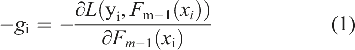
Then, these negative gradients are used as new training objectives to train the mth tree, whose purpose is to make the new tree correct the errors left by all previous trees as much as possible. It is assumed that a base model has been established after the mth iteration. When training the mth tree, the gradient for each sample point is calculated. Then, the model is updated using the gradient descent method

In summary, GBDT optimizes the predictive performance of models by gradually constructing decision trees, making it suitable for various regression and classification problems. By continuously optimizing the loss function, GBDT can effectively improve the accuracy and generalization ability of the model.
Proper preprocessing of the raw dataset is crucial before constructing an intelligent prediction model for the tensile properties of 3D printed thermoplastic composites.29,30 Data preprocessing aims to improve data quality and make it more suitable for the needs of ML algorithms. This work focuses mainly on detecting and handling outliers: outliers may seriously affect the training effectiveness of the model. We identify and handle outliers through boxplots, which identify outliers through quartile ranges.
In order to ensure that the model has sufficient data to learn features and patterns and to improve the training effect, the training set often accounts for a majority of the dataset. However, the model evaluation results may be unstable due to randomness, if the test and validation sets are too small. A 10% ratio is a balance point that neither excessively reduces the size of the training set nor provides sufficient data to evaluate the model.29–31 Therefore, we divide the raw data into the training, testing, and validation sets in an 8:1:1 ratio.
Hyperparameter grid search range.
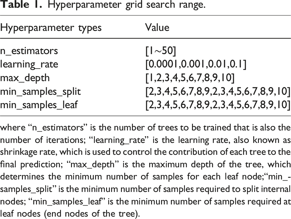
where “n_estimators” is the number of trees to be trained that is also the number of iterations; “learning_rate” is the learning rate, also known as shrinkage rate, which is used to control the contribution of each tree to the final prediction; “max_depth” is the maximum depth of the tree, which determines the minimum number of samples for each leaf node;“min_samples_split” is the minimum number of samples required to split internal nodes; “min_samples_leaf” is the minimum number of samples required at leaf nodes (end nodes of the tree).
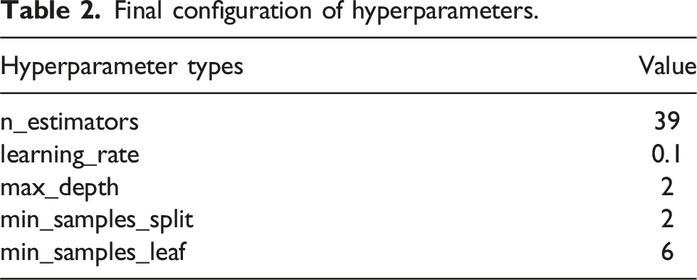
Final configuration of hyperparameters.
Results and discussion as well as model validation
From the optimal parameter combination obtained above, it can be concluded that the GBDT model constructed in this study has a total of 38 iterations and 39 decision trees. The tree 0, 1, 23, and 38 are selected for visualization, as shown in Figure 7 that involves three parameters: Friedman MSE, Samples, and Value. Friedman MSE is an improved mean square error impurity criterion, which is a customized metric used in specific algorithms (gradient boosting) to optimize model performance, considering predicted baseline values and contributions from all constructed trees. Mainly used in gradient boosting algorithms, especially when constructing each tree, to measure the contribution of the tree to the overall model performance. Compared to traditional MSE, Friedman MSE considers the cumulative predicted values of all constructed trees, which means it measures the predictive performance of the model after all iteration steps, while traditional MSE only measures the performance of a single model or prediction step. Samples represent the number of samples used for training in this node. Value is the predicted tensile strength at this node. From Figure 7(a), it can be seen that the content of decision tree 0 is that when the path is less than or equal to 1.5, the Friedman MSE is 38,842 MPa^2, with 89 samples and a predicted value of 0. Then, based on the different printing speeds, the tree was further split. For example, when the printing speed was less than or equal to 485 mm/min, the Friedman MSE decreases to 18,833 MPa^2 with a sample size of 41. At this point, the error is relatively large. By substituting the residuals obtained from decision tree 0 into decision tree 1 in Figure 7(b) for training, the Friedman MSE is 7413 MPa^2, which reduces the initial error. Through continuous iteration, it is known that decision tree 23 in Figure 7(c) is different from the previous approach where only speed was used as the partition node. At this point, the tree begins a new split based on different temperature and continues to iterate until decision tree 38 in Figure 7(d) is reached. At the end of the iteration, the optimal set of learners with the best performance is obtained. 39 decision trees were weighted and summed to obtain the GBDT model that can effectively predict the tensile properties of 3D printed continuous fiber PEEK composites. (a) Decision tree 0, (b) (a) Decision tree 1, (c) Decision tree 23, and (d) (a) Decision tree 38 with the unit of printing velocity (mm/min) and Friedman_mse (MPa^2).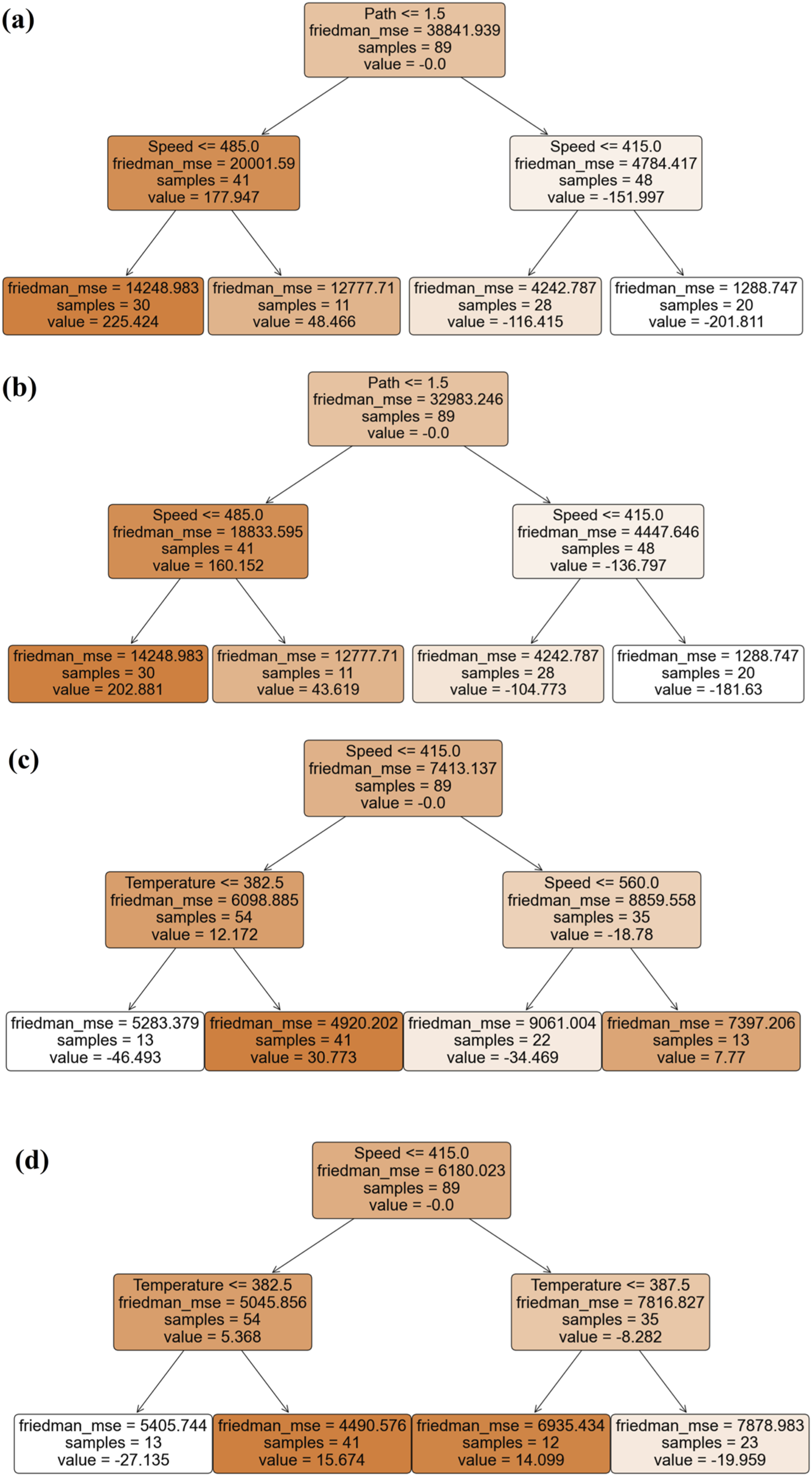
Figure 8 illustrates the relative importance of key printing parameters: printing path, speed, and temperature. The analysis reveals a striking dominance of the printing path, with a relative importance of 0.8, followed by printing speed at 0.15, and printing temperature at 0.05. This pronounced influence of the printing path on the mechanical properties of the 3D printed composites can be attributed to several factors, including fiber orientation and alignment, interfacial bonding, and stress distribution patterns.8–17 The high relative importance of the printing path is likely due to our selection of orthogonal printing and unidirectional printing paths. In orthogonal printing, half of the fiber orientation is perpendicular to the stretching direction, whereas unidirectional printing aligns fibers predominantly along the load-bearing axis. This fundamental difference in fiber orientation results in a significant disparity in the tensile strength between orthogonally and unidirectionally printed samples, with the latter exhibiting approximately twice the overall strength. This stark contrast in mechanical performance underscores the critical role of the printing path in determining the final properties of the composite. The dominance of printing path can be further explained by its influence on: (1) fiber orientation and alignment, which directly impacts the anisotropic behavior of the composite; (2) interfacial bonding and interface area between successive layers; (3) stress distribution patterns within the printed structure and (4) formation and distribution of voids, which affect the overall structural integrity. While printing speed and temperature also play important roles, their effects appear to be less pronounced under the specific experimental conditions of this study. The printing speed, with a relative importance of 0.15, demonstrates a more significant influence on material properties compared to temperature. This could be attributed to its direct impact on the cooling rate of the deposited material, affecting polymer chain alignment and crystallization behavior.3–13 The printing temperature, showing the lowest relative importance of 0.05, still contributes to the overall performance of the printed composites. Its influence likely stems from its effect on polymer chain mobility and interdiffusion at layer interface.4–12 However, within the range of temperature explored in this study, its impact appears to be less critical compared to the printing path and speed. Importance of the characteristics of printing path, speed, and temperature.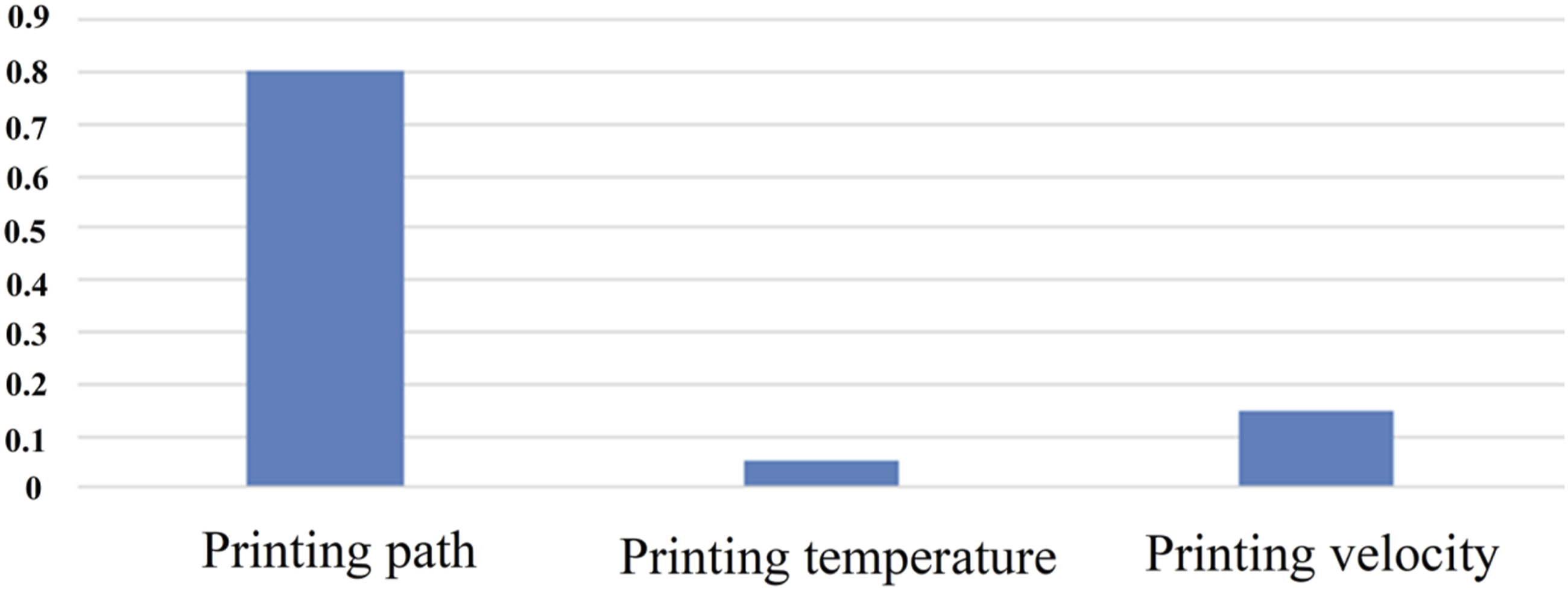
The effects of printing parameters demonstrate clear positive/negative trends: (1) Printing speed showed a negative impact beyond 400 mm/min (∼10% strength reduction, p < .01) due to insufficient interlayer cooling, but exhibited optimal performance in the 300–400 mm/min range (∼900 MPa peak at 330 mm/min). (2) Nozzle temperature exceeding 400°C led to a ∼10 MPa/10°C strength decline (p = .003) from PEEK degradation, while the 375–390°C range optimized polymer flow and fiber wetting (R2 ≈ 0.9 for temperature-strength correlation). (3) Unidirectional paths provided a ∼15% strength advantage over orthogonal designs (importance score 0.8 vs 0.2) by aligning fibers with the load axis.8,9 These findings align with the GBDT model’s feature importance analysis and explain the ∼2.5-fold strength variation across parameter combinations.
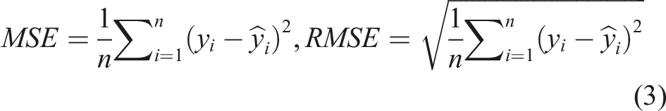
The predictive performance of the GBDT model using metrics such as the Mean Squared Error (MSE), Root Mean Squared Error (RMSE) and Coefficient of Determination (R-squared, R2) is evaluated. MSE and RMSE are defined as
37
The Coefficient of Determination R2 is defined as
37
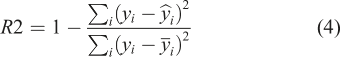
The value of R2 is between 0 and 1. The closer the R2 value is to 1, the stronger the explanatory power of the model, indicating that the model can better capture the variability of the data. An R2 value of 0 indicates that the model’s predictions are as good as using the mean for prediction, while an R2 value of 1 indicates that the model fits the data perfectly.
In the training process of gradient boosting trees, as the number of iterations increases, MSE typically decreases while R2 increases. This is due to each tree’s effort to correct residuals from previous iterations, thereby enhancing the model’s predictive accuracy.
33
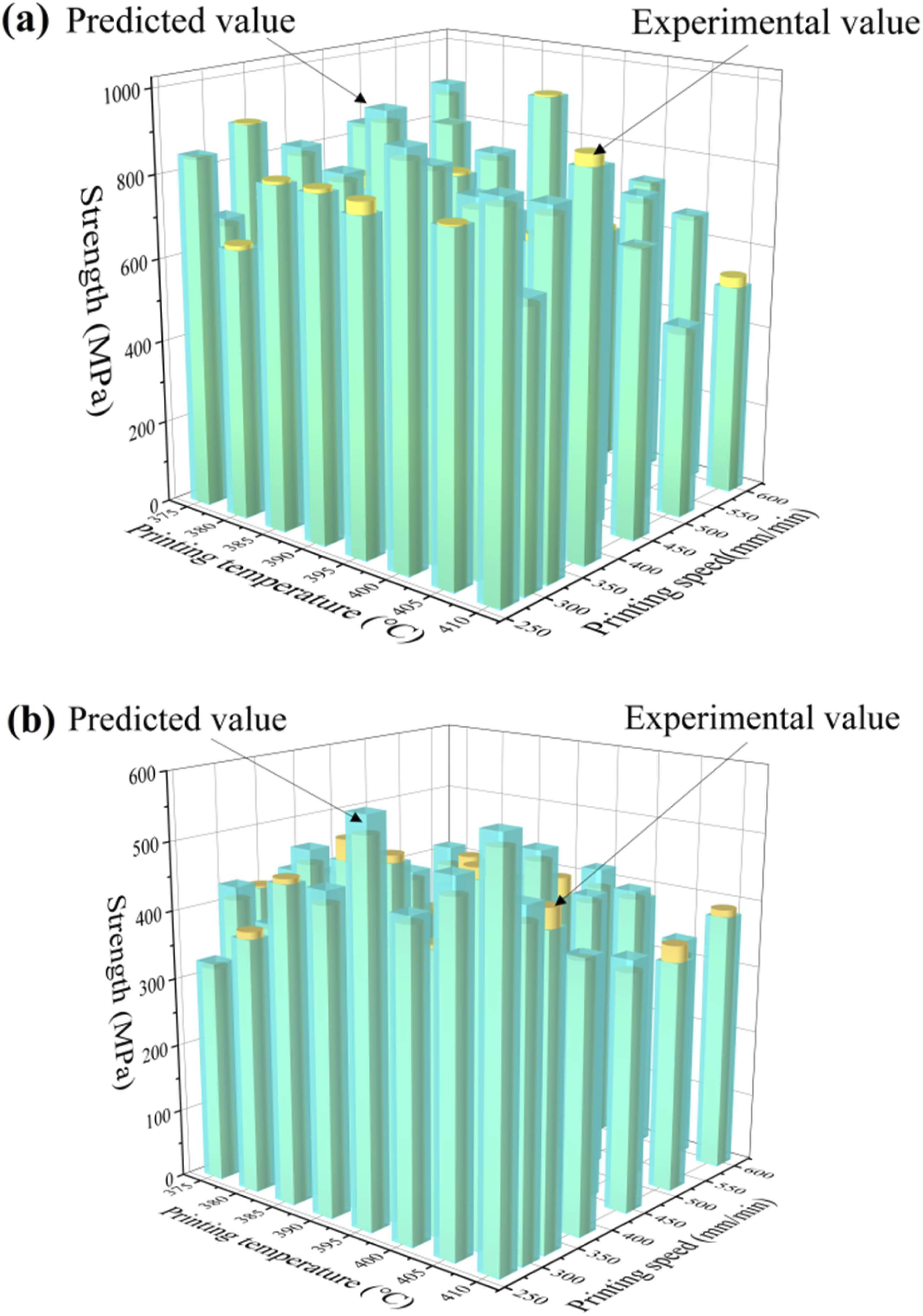
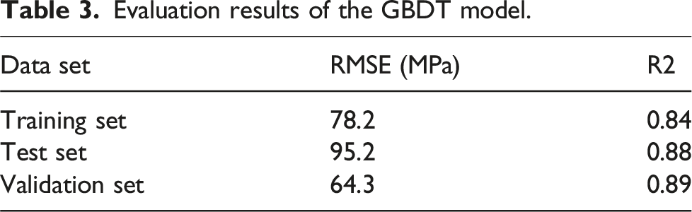
To prevent overfitting, this study employs an early stopping method, monitoring the MSE or R2 on the validation set to determine the optimal point to halt training.34,35 Figure 9 illustrates the evolution of MSE and R2 with iterations, respectively. Figure 10 shows the predicted and experimental strengths of composites under different temperature and speed, and the unidirectional and orthogonal printing paths, respectively. The overall stability and accuracy of model are evaluated through cross-validation, with performance metrics calculated across different data subsets, as presented in Table 3. The results demonstrate robust performance and consistency across training, test, and validation sets, underscoring the strong generalization capabilities of model.27–29 The R2 values, ranging from 0.84 to 0.89, indicate that the model effectively captures a high proportion of variance in the target variable (tensile strength of composites) across all datasets. This suggests successful modeling of the complex, nonlinear relationships inherent in 3D printed composite materials.30,31 The RMSE values exhibit some variation across sets, with the validation set showing the lowest error (64.3 MPa), followed by the training set (78.2 MPa), and the test set displaying the highest error (95.2 MPa). While there is some discrepancy, the difference is not drastically large, indicating reasonable stability in the model’s predictions. Notably, the slightly better performance on the validation set compared to the training set, in terms of both RMSE and R2, is particularly encouraging as it suggests the model is not overfitting to the training data.34–36 The model’s ability to maintain high R2 values and relatively low RMSE across different datasets demonstrates its robust generalization ability, a crucial aspect in ML application for materials science.27–29 This performance stability can be attributed to the GBDT’s ensemble nature, which combines multiple weak learners to create a robust predictor,
33
as well as the careful hyperparameter tuning through grid search.35,36 However, the slight variations in performance across sets, particularly the higher RMSE in the test set, suggest potential for further optimization. Future work could focus on enhancing consistency and potentially reducing RMSE, especially in the test set. This could involve expanding the model’s applicability by incorporating a wider range of printing parameters and material compositions.29–31 In conclusion, the GBDT model exhibits good stability and accuracy across different data subsets, with strong predictive power and generalization ability. The proposed approach demonstrates strong generalizability beyond the CF/PEEK system, as evidenced by its foundational design and validation framework. The GBDT framework is inherently adaptable to various material systems due to its ability to capture nonlinear interactions among processing parameters and mechanical properties. While this study focuses on CF/PEEK composites, the model’s emphasis on key parameters (e.g., printing path, temperature, and speed) aligns with universal aspects of polymer matrix composite processing. This adaptability is supported by the consistent performance of GBDT in related fields (e.g., metal additive manufacturing), where similar parameter-property relationships were successfully modeled. Evolution process of (a) MSE and (b) R2 with iterations. Predicted and experimental strengths of 3D printed CF/PEEK composites under different temperature and speed, and (a) the unidirectional printing path and (b) the orthogonal printing path. Evaluation results of the GBDT model.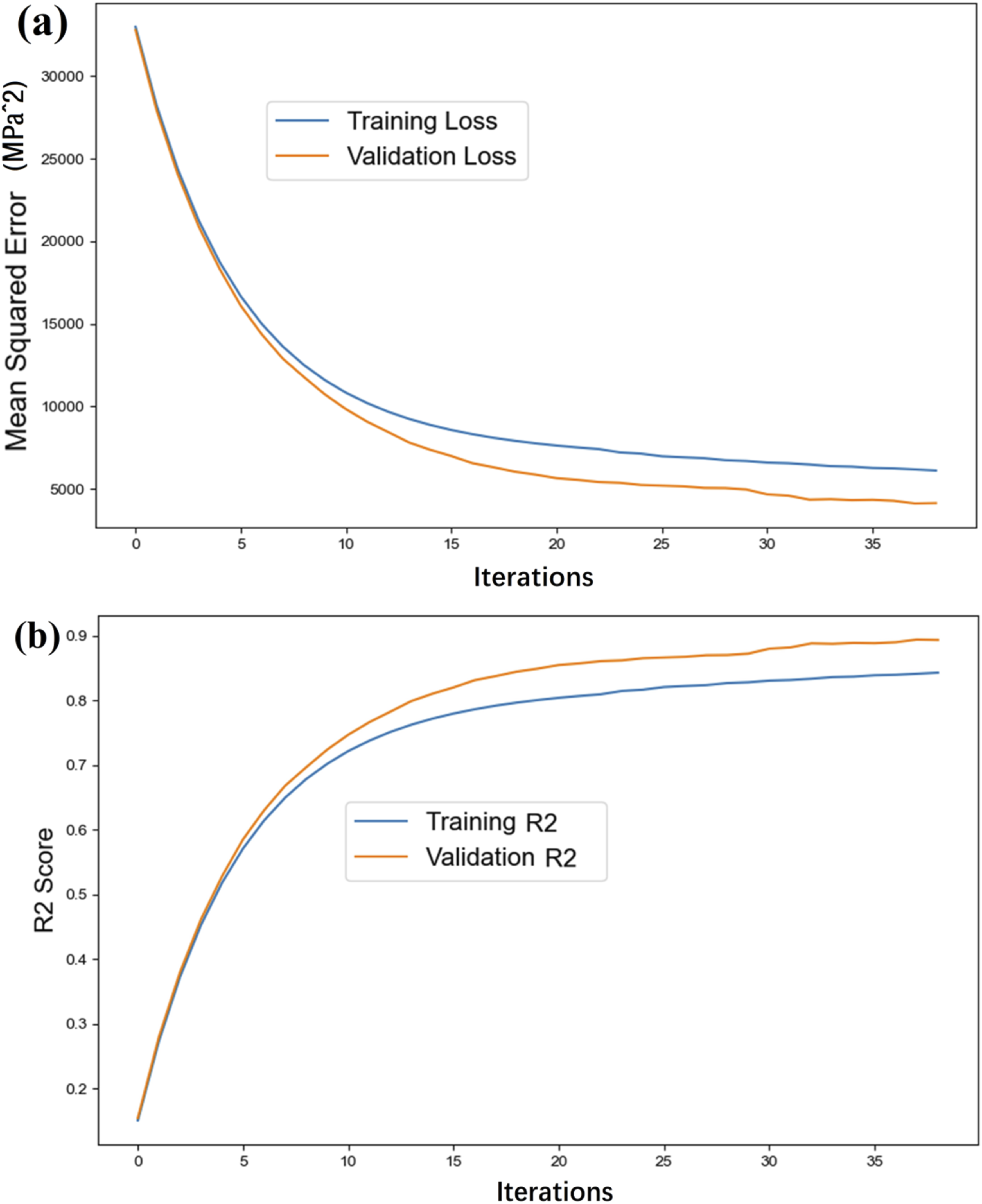
Similarly, Cai et al. 29 tailored the interfacial properties of 3D printed composites successfully by leveraging a parameter optimization approach, which results in precise control of the final characteristics. The optimization process benefits from the computational speed of ML models, allowing the researchers to explore a large design space more efficiently than traditional experimental approaches. However, the reliance on specific training data might limit the accuracy when applied to more generalized or unseen data sets. In addition, the efficiency of the model may decrease if not paired with robust optimization techniques or if the computational cost of data generation becomes excessive. Ferdousi et al. 30 integrated theoretical modeling with ML to predict the performance of 3D printed lightweight hybrid composites. The use of ML enhances the accuracy of predictions by effectively capturing complex interactions in the material structure. The robustness of model is strengthened by the integration of theoretical modeling, providing a more physics-based foundation to the ML predictions. This hybrid approach improves the generalizability of the predictions across different composite configurations. However, like most ML-driven models, accuracy may degrade when the training data does not adequately cover all variations of the material properties. Polyzos et al. 31 employed neural networks to segment X-ray computed tomography images and model the elastic properties of 3D printed composite filaments. In the work of Chen et al., 32 the measured data proved the continuous fiber reduces the printing precision on width and thickness and the printing stability on thickness, while it improves the width stability in the XY horizontal plane.
Finally, in order to deeply comprehend the intricate correlation between printing parameters and the mechanical properties of 3D printed composite, an extensive examination of the interpretability of ML algorithms coupled with an analysis of the physical significance of parameter features is quintessential. The application of GBDT offers a significant advantage in modeling complex, nonlinear relationships that underpin the process-structure-property paradigms inherent to 3D printing technologies. Goh et al. 27 underline the transformative potential of ML in 3D printing, articulating that ML algorithms can unveil latent patterns and dependencies between seemingly disparate process parameters and the resultant mechanical properties of printed materials. This revelation is crucial in decoding the complexity of additive manufacturing processes where variables such as temperature, speed, and path intricately interplay to dictate the final material characteristics. In bridging the gap between printing parameters and physical properties, the work of Cai et al. 29 is particularly illuminative. Their research demonstrates how optimizing the interfacial properties of 3D printed continuous natural fiber reinforced polypropylene composites through parameter adjustments can be effectively guided by ML methods, thus providing a clear linkage between empirical practice and theoretical modeling. This approach underscores the essential role of ML in translating quantitative insights into actionable process adjustments. Moreover, Chen et al. 32 contributed significantly to the discussion by developing mathematical models that assess tensile properties and fracture behavior of 3D printed composites. Their models provide a granular view of how different printing parameters, like extrusion temperature, print speed, and fill patterns, affect mechanical performance, further enabling a predictive understanding of material behavior under various conditions. The comprehensive review by Zhai et al. 1 also served as a foundational piece in correlating printing parameters with composite material performance. By highlighting the vast array of process variables that can affect the mechanical integrity of fiber reinforced thermoplastics, thus offering a broad perspective on the optimization of such parameters for enhanced material performance. Lastly, the investigative work by Zhang et al. 17 provided critical insights into the mechanical characterization of continuous carbon fiber reinforced thermoplastics, emphasizing the role of print path, speed, and temperature in defining the tensile strength and fracture behavior of the final printed composite. In summary, harnessing the insights provided by ML to elucidate the complex, nonlinear relationships between 3D printing parameters and the resultant material properties serves as a cornerstone in the advancement of additive manufacturing technologies.
Conclusion
The paper constructs a tensile performance prediction model for 3D printed continuous fiber PEEK composite thermoplastic composites based on the GBDT algorithm, and optimizes the hyperparameters by combining the 3-fold cross-validation and grid search methods. A total of 120 flat CF/PEEK composite samples are printed under controlled conditions, and their tensile properties are tested. The influence of the printing path, printing speed, and nozzle temperature on the tensile performance of 3D printed continuous fiber PEEK composite is accurately predicted. Three main conclusions are obtained: (1) The optimal parameter combination was determined through 120 experimental trials as unidirectional printing path (fiber orientation angle <5°), printing speed of 330 ± 10 mm/min, and nozzle temperature of 380°C, achieving maximum tensile strength of 976 MPa with 2.5-fold improvement over baseline conditions (270 mm/min, 375°C) and strength standard deviation controlled within 5%; (2) Parameter sensitivity analysis revealed: (a) printing speed exhibited nonlinear influence with peak strength plateau between 300 and 400 mm/min, while speeds exceeding 450 mm/min caused 12%/10 mm/min strength reduction; (b) temperature sensitivity window spanned 375–390°C, with >400°C leading to 8.7 MPa strength decrease per 10°C increment; (c) printing path dominated performance with relative importance of 0.8, significantly higher than speed (0.15) and temperature (0.05); (3) The GBDT model demonstrated robust predictive performance after 3-fold cross-validation: testing set R2 = 0.89 (RMSE = 64.3 MPa), training/validation set R2 difference <0.03 indicating no overfitting, and <7% prediction error for unseen parameter combinations (maximum deviation 68 MPa in validation set). From an industrial perspective, while CF/PEEK composites excel in aerospace and medical device applications requiring high strength-to-weight ratios and biocompatibility, their high material costs and specialized printing equipment currently limit widespread adoption in mass production industries such as manufacturing of automotive, aerocraft, and ocean engineering structures.
Although this study has achieved some results in the prediction of tensile properties of 3D printed thermoplastic composites, there are still many areas worthy of further exploration and improvement: (1) the GBDT ML model developed in this study, while effective, may benefit from more extensive datasets to improve their predictive accuracy and robustness; (2) the current approach does not account for potential long-term effects such as environmental degradation or fatigue behavior of the printed composites. Future research could address these aspects by incorporating time-dependent studies and considering a broader range of mechanical properties and testing conditions; (3) the present study primarily focused on macroscopic mechanical properties. A more comprehensive understanding could be gained by investigating the microstructural characteristics of the printed composites and their correlation with mechanical performance; (4) while our study demonstrated the significance of printing path in determining mechanical properties, further work is needed to develop optimized path planning algorithms that can automatically generate ideal printing strategies based on desired mechanical characteristics for such as 3D printed CF/PEEK honeycomb, sandwich and origami structures.
Future work should focus on expanding the model’s applicability to multi-material systems and developing real-time adaptive printing control algorithms to further enhance process robustness and scalability for industrial applications.
Footnotes
Author contributions
Liu Pengfei: Writing-review and editing, Writing-original draft, Project administration, Methodology, Investigation, Funding acquisition, Conceptualization. Chang Baoning: Conceptualization, Data curation, Investigation, Funding acquisition, Validation. Xu Chongxiao: Data curation, Investigation. Zhang Wuxiang: Project administration, Supervision, Validation. Yang Tong: Data curation, Investigation. Wu Tao: Investigation, Supervision.
Declaration of conflicting interests
The author(s) declared no potential conflicts of interest with respect to the research, authorship, and/or publication of this article.
Funding
The author(s) disclosed receipt of the following financial support for the research, authorship, and/or publication of this article: This work was supported by the grant from National Natural Science Foundation of China (No: 52475171), Aeronautical Science Foundation of China (No. 2023M057076001), Ningbo Key Projects of Science and Technology Innovation 10 2025 Plan (2023Z054, 2022Z070), Opening Funding of State Key Laboratory of Structural Analysis for Industrial Equipment, Dalian University of Technology (No. GZ22101).
Data Availability Statement
All relevant data are within the manuscript and its supplementary files.