
Abstract
This work proposes an experimental evaluation based on digital image correlation (DIC) technology to obtain the cohesive zone model (CZM) parameters for coated fabrics. A calculation method for fracture energy was proposed based on the J-integral theory, and crack tip opening displacement (CTOD) was obtained through virtual extensometers. For specimens with single-edge crack (SEC) and center crack (CC), a bilinear traction-separation law was established to clarify the influence of crack configuration on the CZM parameters. The accuracy of the experimentally measured CZM parameters can be validated through an inversion approach integrating Isight and Abaqus. The results indicate that the relative errors of the maximum cohesive traction and the corresponding cohesive separation displacement between the two specimen types are both less than 2%. In contrast, the crack configuration has a significant impact on the fracture energy and the critical separation displacement. Specifically, the CC specimens demonstrate more sufficient energy dissipation due to more uniform stress distribution, with fracture energy reaching 45.69 kJ/m2 and critical separation displacement measuring 1.006 mm. The verification revealed that the relative error between measured and inversion parameters was less than 5%, and the simulation curves accurately reproduced the fracture mechanical characteristics of the coated fabrics.
Introduction
Coated fabrics possess advantages such as lightweight, high strength, ease of installation, and excellent formability, making them widely used in modern large-span structures, including sports stadiums, transportation hubs, and exhibition centers. 1 However, as the primary enclosure components of membrane structures, coated fabrics are susceptible to localized initial defects caused by manufacturing defects, installation scratches, or windborne debris. 2 During the service of membrane structures, these defects can propagate and evolve into catastrophic tear failures under the influence of sudden strong winds or short-term gusts.3,4 A notable example is the structural damage inflicted on the London Millennium Dome by Storm Eunice in 2022. Therefore, accurate prediction of crack initiation and propagation in coated fabrics is a crucial prerequisite for ensuring the safety and durability of membrane structures.
Well-established technical approaches have been formed for existing numerical methods to characterize crack propagation behavior, including the extended finite element method (XFEM),5,6 phase field method (PFM),7,8 and cohesive zone model (CZM).9,10 The XFEM achieves decoupling of cracks from meshes by introducing enrichment functions, which enables the description of crack propagation without mesh reconstruction. However, the accuracy of crack surface tracking relies on the element discretization density, and it is difficult to capture the damage evolution of crack propagation precisely. The PFM realizes smooth characterization of crack behaviors by means of continuous field variables and does not require a preset crack path. Nevertheless, it suffers from high computational cost and stringent requirements for the calibration accuracy of constitutive parameters. A typical characteristic of crack propagation in coated fabrics is the formation of a distinct damage transition zone at the crack tip, which is highly consistent with the damage evolution mechanism described by the CZM.11–14 Thus, the CZM is the preferred numerical method for describing the tearing process of coated fabrics.15,16 This model defines the mechanical response of the damaged zone as the traction-separation law, fundamentally avoiding the numerical convergence problems caused by stress singularity at the crack tip in classical fracture mechanics analysis.17–19
The traction-separation law of the CZM has multiple forms including linear, bilinear, exponential and trapezoidal types,20–22 which can adapt to the requirements for the fracture behaviors of various materials. Each form is defined by parameters such as initial stiffness, maximum cohesive traction, critical separation displacement and fracture energy, and the values of these parameters directly determine the characteristics of the constitutive curve and the laws of mechanical response.23,24
The methods for obtaining CZM parameters include the numerical inversion method, theoretical derivation method and experimental testing method. Among them, the numerical inversion method is based on experimental macroscopic mechanical responses. It establishes the correlation between CZM parameters and mechanical responses via finite element simulation, iteratively adjusts parameters through optimization algorithms to minimize the deviation between simulated and experimental data, and then infers the CZM parameters inversely. Shi et al. 25 proposed an inversion framework based on the multi-island genetic algorithm, which was validated by double cantilever beam tests and realized accurate parameter identification. Tran et al. 26 developed a field projection method based on the Maxwell–Betti reciprocal theorem, reconstructing the traction-separation law from the strain field information of monotonic fatigue cyclic loading and unloading. Chen et al. 27 adopted the improved Levenberg–Marquardt method and achieved accurate parameter identification by minimizing the deviation between simulated and experimental results at key points on the curve. However, the numerical inversion method relies on the indirect mapping relationship between macroscopic mechanical responses and numerical models. The improper selection of initial parameters is likely to cause the inversion process to converge to a local optimal solution. In addition, although the inverted parameters can realize numerical fitting of macroscopic mechanical responses, this method lacks a direct experimental verification approach for the parameters themselves, making it difficult to confirm that the inverted parameters accurately characterize the material’s fracture properties from the perspective of physical essence.
The theoretical derivation method is a commonly used technical approach for determining the fracture energy in CZM parameters.28,29 In relevant studies on coated fabrics, some scholars often approximate the material as isotropic to simplify the solution process of crack parameters. While the fracture toughness of isotropic materials under different crack configurations can be directly obtained from well-established analytical solutions in existing mechanical handbooks, 30 this simplification completely neglects the anisotropic characteristics of coated fabrics. This results in a significant deviation between the theoretically estimated fracture toughness and the actual mechanical behavior, which fails to meet the accuracy requirements for engineering applications. For this reason, He et al. 31 combined the virtual crack closure technique with a nonlinear constitutive model, effectively resolving the issue of underestimated energy release rate for coated fabrics. Minami 32 proposed a fracture energy calculation method that integrates the Hedgepeth yarn model with the Griffith energy balance theory, yet this method still does not account for the influence of the nonlinear mechanical behavior of materials. Zhang et al. 33 further developed an incremental energy balance theory, which quantitatively incorporates material nonlinear effects into the fracture energy prediction model and thus greatly improves the accuracy of theoretical calculation results.
Compared with the indirect mapping nature of numerical inversion and the limitations of simplified assumptions in theoretical derivation, the experimental testing method is the most direct technical approach for obtaining CZM parameters with clear physical meanings.34,35 Among them, DIC is a key technical method for analyzing the fracture behaviors of materials in experimental testing with its high-precision full-field deformation and strain capture capability.
Baldassarre et al. 36 verified that the DIC technique has significant accuracy advantages over conventional measurement methods for strain measurement of anisotropic composite materials, and clarified the selection criteria for key parameters of DIC. Subsequently, scholars including Panich et al., 37 Barnwal et al., 38 and Yildiz et al., 39 respectively, verified the applicability of the DIC technique in fracture behavior characterization of metal sheets and anisotropic deformation analysis, and further improved the accuracy control methodology for DIC-based strain measurement. Wang et al., 40 Huo et al., 41 and Fong et al. 42 successfully extracted CZM parameters related to composite delamination and adhesive joint fracture using the DIC technique.
The above studies have fully verified that the DIC technique can accurately achieve strain measurement and fracture behavior characterization of metals and rigid composite materials, which lays a solid methodological foundation for the present study. For coated fabrics, existing studies have also introduced the DIC technique to carry out relevant investigations. Bao et al. 43 conducted a quantitative analysis of the evolution law of the strain field during the tearing process of coated fabrics using the DIC technique, and revealed the mechanism by which the strain concentration effect at the crack tip dominates the tearing behavior. He et al. 2 obtained full-field strain data based on the DIC technique, analyzed the strain distribution characteristics at the crack tip under biaxial loading conditions, and further qualitatively elucidated the tearing failure mechanism of coated fabrics.
In summary, the existing DIC-based fracture parameter test methods are mainly developed for metals and rigid composite materials. These test systems are established based on the small-deformation linear elastic fracture mechanics assumption, which has essential differences from the large-deformation nonlinear fracture behavior of coated fabrics. Meanwhile, the existing methods is designed for interlayer delamination failure of rigid materials, which is completely mismatched with the in-plane tearing fracture characteristics of coated fabrics, making them impossible to be directly applied. In addition, existing DIC studies on coated fabrics are still limited to the qualitative characterization of strain fields, and no method has been established to convert DIC full-field deformation data into quantitative CZM parameters for material fracture characterization.
This work proposes an experimental measurement method for the CZM parameters of coated fabrics. First, a nonlinear J-integral calculation formula suitable for coated fabrics is derived, which takes full account of the large deformation characteristics of the material. Subsequently, uniaxial tensile tests are carried out on single-edge crack (SEC) and central crack (CC) specimens. The full-field deformation at the crack tip is captured by the DIC technique, realizing high-precision measurement of the crack tip opening displacement (CTOD). On this basis, the constitutive parameters of the bilinear traction-separation law for coated fabrics are directly calculated, and the influence of crack configuration on CZM parameters is quantitatively elucidated. Finally, the accuracy of the measured parameters is verified by the Isight-Abaqus numerical inversion method, with the relative error of peak load between the numerical simulation results and the experimental results less than 4%.
Theory and methods
CZM of coated fabrics
Experiments and well-established existing studies have consistently shown that a distinct triangular fracture process zone will form at the crack tip of coated fabrics before the occurrence of macroscopic cracks under uniaxial tensile load.44–46 This core feature is the applicable premise of the CZM, and the mechanical behavior of this zone can be accurately described by the traction-separation law of CZM.
47
Specifically, the damage characteristics inside the fracture process zone at the crack tip include fiber bridging, fiber pull-out and coating-fabric interface debonding, as illustrated in Figure 1. The CZM of coated fabrics and the bilinear traction-separation law.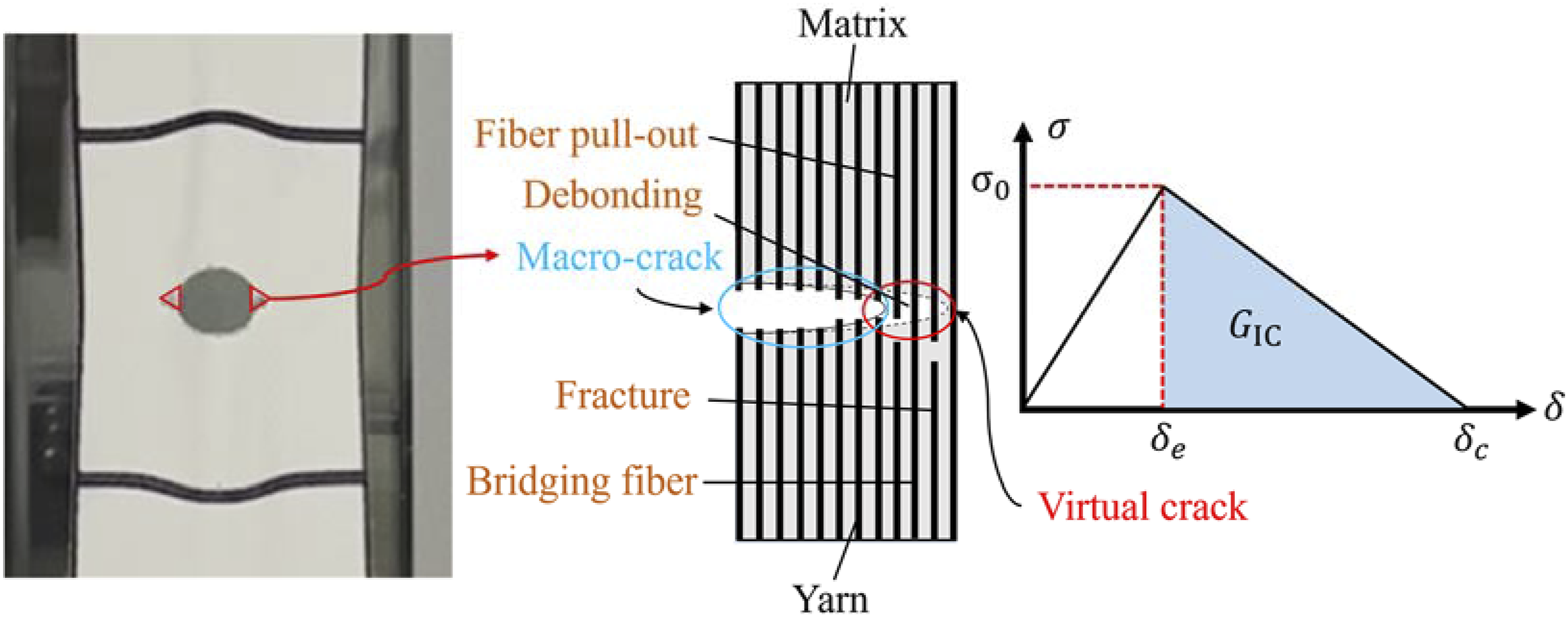
This mechanical behavior can be effectively described using a simple bilinear traction-separation law.
44
When the traction load reaches its maximum value
Fracture energy and measurement method
The coated fabric is a type of flexible composite material. Despite the geometric nonlinearity and material nonlinearity, its fracture process involves multiple damage mechanisms, such as fiber slippage and coating cracking in the cohesive zone. The energy dissipation is dominated by elastic dissipation and cohesive zone separation dissipation, with the plastic work consumption being relatively small. Under monotonic loading conditions, the critical J-integral value can be approximated as equal to the fracture energy

The path-independent J-integral theory proposed by Rice
48
transforms the energy transfer under external loading into a contour integral form. The mathematical expression is as follows
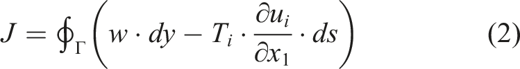
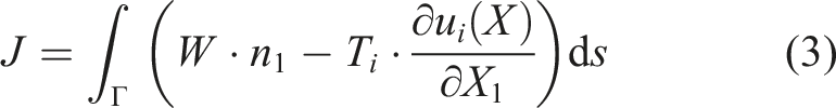
Equation (2) is applicable to small deformations in linear elastic materials. However, coated fabrics exhibit pronounced material nonlinearity and large deformation characteristics during crack propagation. Direct application of equation (2) in such cases results in significant errors. To address this issue, Eshelby,
49
building upon Rice’s theoretical framework, derived an expression for the J-integral applicable to nonlinear elastic materials under finite deformation conditions
Considering that the applied loads and displacement fields can be directly obtained through experimental methods, a closed curve The integration path for J-integral.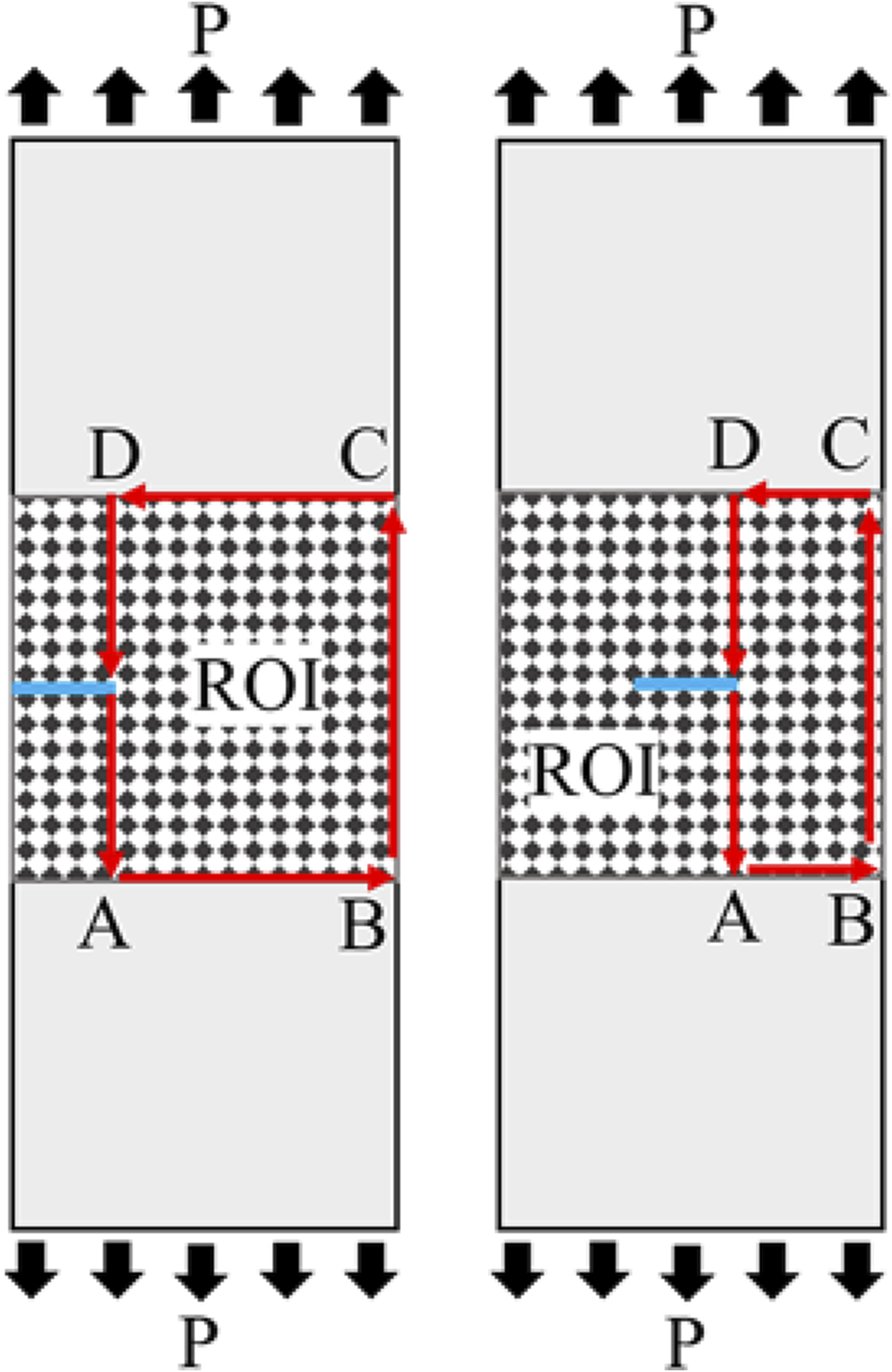
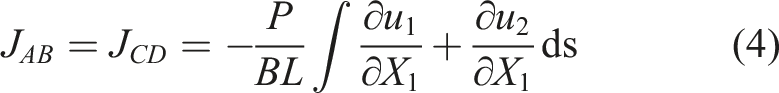
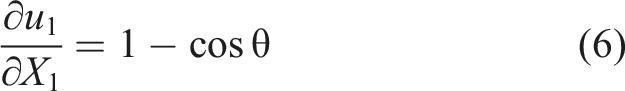
Within this integral path, it can be determined through the external load and the displacement gradient
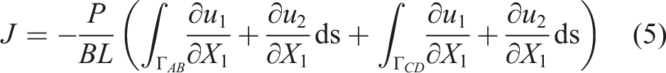
The displacement data were extracted using the virtual extensometer, with the specific arrangement illustrated in Figure 3. Virtual extensometer The arrangement of the virtual extensometers.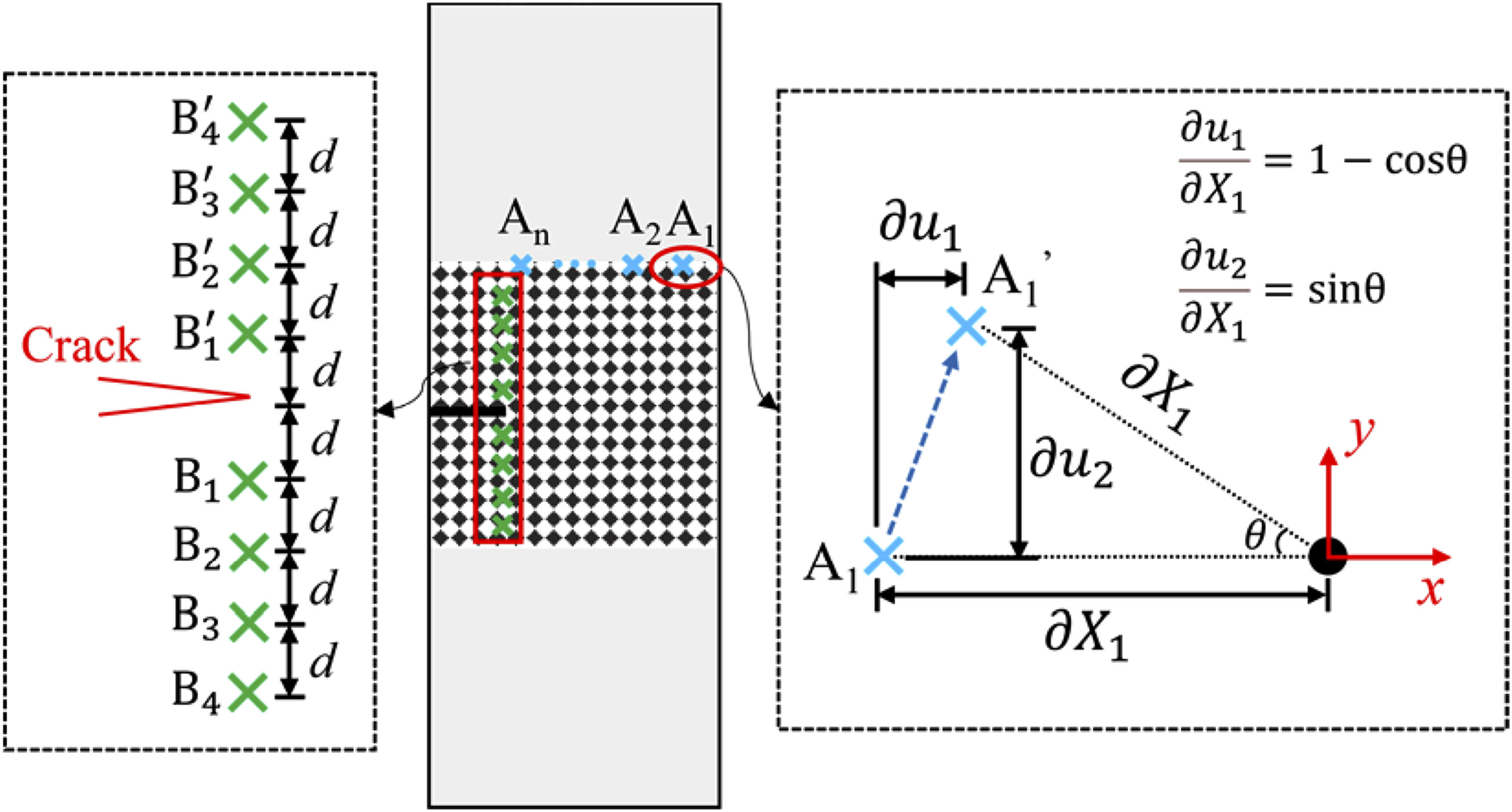
Equation (5) can be expressed as
Measurement of CTOD
The failure of pixel matching may result in the loss of displacement data near the crack tip. Therefore, directly positioning the virtual extensometers adjacent to the crack tip fails to capture the CTOD.
50
The first pair of virtual extensometers (


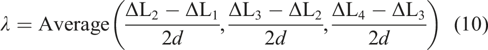
Therefore, the expression of CTOD is as follows

Experimental results and discussion
Specimen and experimental setup
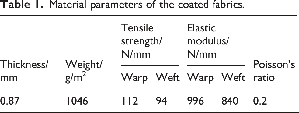
Material parameters of the coated fabrics.
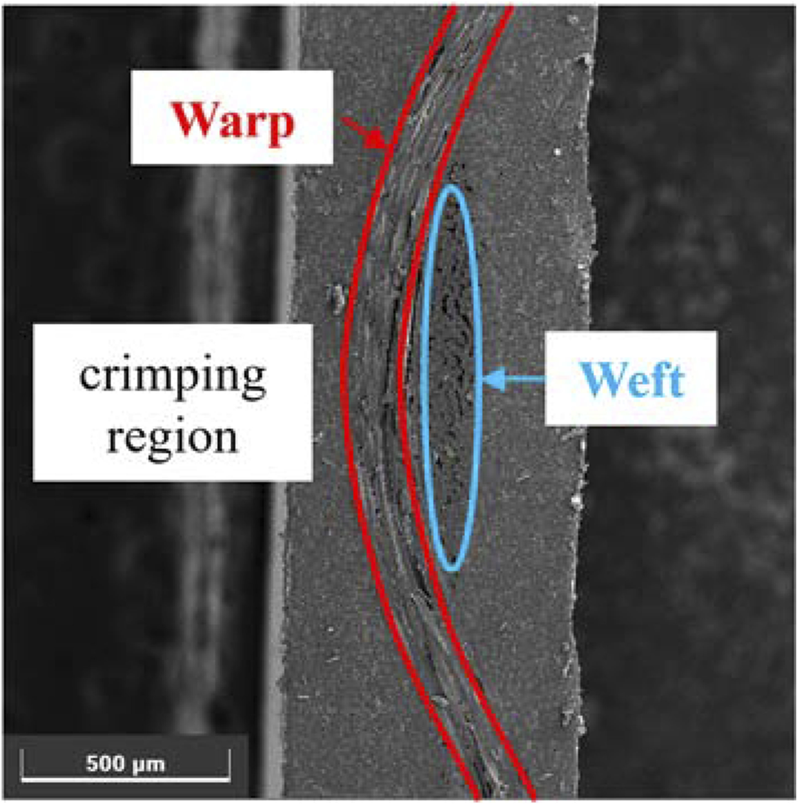
Crimping region of coated fabrics.
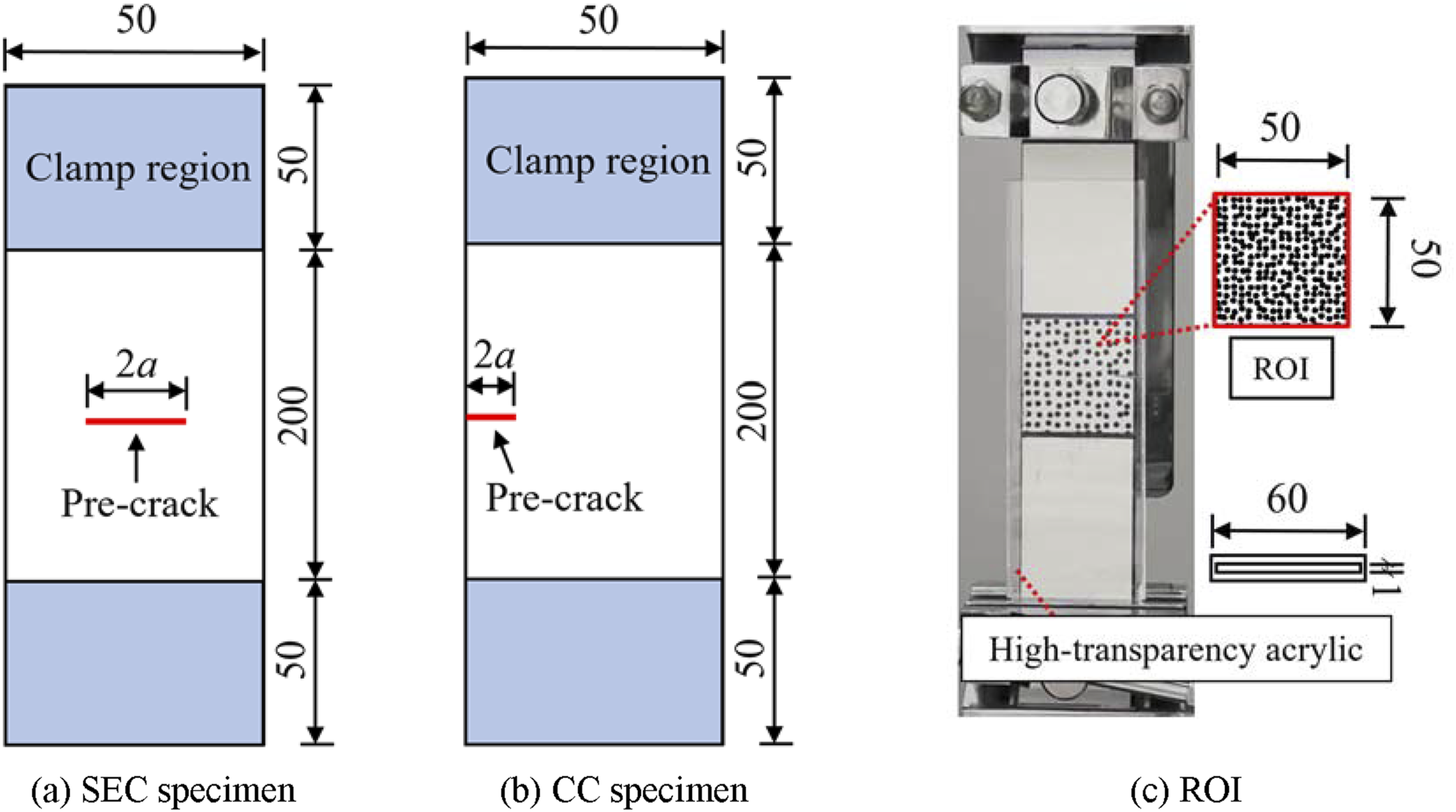
Schematic diagram of specimen (Unit: mm). (a) SEC specimen; (b) CC specimen; (c) ROI.
During the uniaxial tensile process, the crack area of the flexible coated fabric is prone to out-of-plane deformation and wrinkling. This phenomenon will directly reduce the measurement accuracy of the in-plane displacement and strain field of the specimen by the DIC system, and further lead to deviations in the J-integral calculation results. To eliminate this adverse effect, a set of high-transparency acrylic constraint plates was installed on both outer sides of the specimen, as shown in Figure 5(c). A 1 mm gap was reserved between the two acrylic plates, which was slightly larger than the thickness of the test specimen. This design can completely restrict the out-of-plane warping and wrinkling in the crack area, while hardly introducing additional in-plane frictional resistance that would interfere with the tensile deformation of the specimen. In addition, the high light transmittance of the acrylic plate ensures that the camera can clearly capture the speckle pattern on the specimen surface without image distortion or light reflection interference.
The experimental equipment is depicted in Figure 6. All loading tests were performed under controlled environmental conditions, maintained at 25 ± 1°C and 50% relative humidity, utilizing a WDW-200M universal testing machine. The loading rate was fixed at 10 mm/min to replicate quasi-static loading scenarios. To ensure statistical robustness, three specimens were examined for each crack configuration. To precisely measure the deformation of the fracture process zone during crack propagation, a high-resolution industrial cameras were employed. Setup of experimental equipment.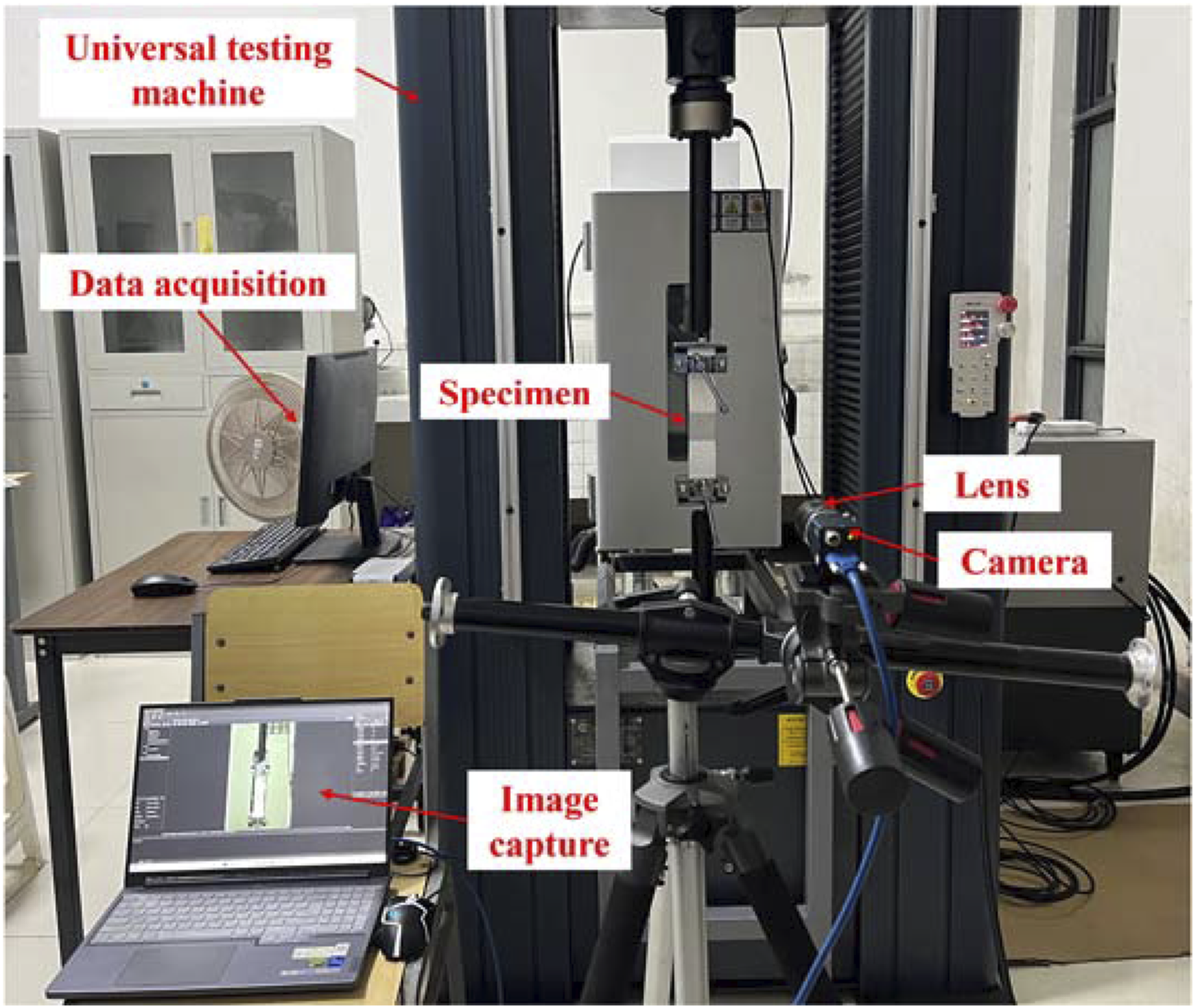
Since the out-of-plane deformation of the coated fabric was completely restricted by the high-transparency acrylic constraint plates in the test, the 2D-DIC technique was adopted for measurement. To adapt to the large deformation characteristics of the coated fabric, water-transfer prefabricated random speckle stickers were used to prepare the speckle pattern. Random circular black speckles with a single speckle diameter of 3 mm and a black-white duty cycle of 1:1 were generated by computer, and were transferred onto the specimen surface cleaned with anhydrous ethanol via the water-transfer process.
The image processing and calculation were completed using the open-source software Ncorr. 52 Taking the unloaded initial image as the reference, the area near the crack was defined as the ROI. The full-field displacement data were obtained through iterative calculation with discrete subsets. After exporting the displacement and strain data in the horizontal and vertical directions for all load steps, automated processing including displacement extraction, CTOD calculation and J-integral calculation was completed through a self-developed script.
Fracture behavior
Figure 7 presents the load-displacement curves for the SEC and CC specimens. Both curves exhibit linear behavior in segments OA and AB. In segment OA, the displacement fields of the SEC and CC specimens display a uniform distribution with minimal gradients, primarily governed by the geometric deformation of the yarns within the coated fabrics. The initially curled yarns gradually straighten under initial loading, without significant damage to either the yarns or the coating. The overall stiffness of the material in this phase is determined by the elastic modulus of the yarns and the woven fabric structure. Load displacement curves and displacement field of specimens with different crack lengths. (a) SEC specimen; (b) CC specimen.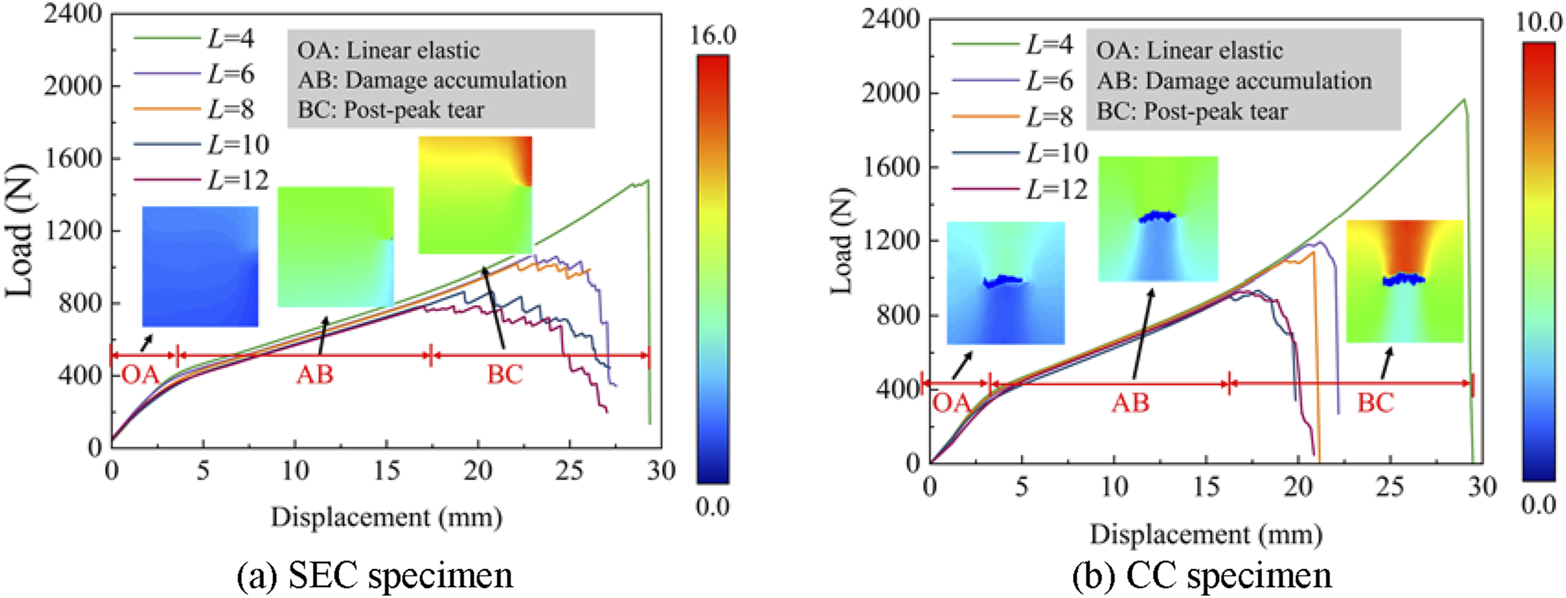
At segment AB, the displacement field becomes increasingly non-uniform, with pronounced displacement jumps observed on either side of the crack. The overall stiffness decreases markedly compared to segment OA. Although the crack opening displacement continues to increase during this stage, the crack tip does not exhibit significant propagation. The cohesive zone at the crack tip remains in a damage accumulation phase and has not reached a critical fracture state.
Segment BC corresponds to the post-peak tearing phase, characterized by two distinct failure modes: brittle fracture and progressive fracture. The critical crack width at which the failure mode transitions varies depending on the crack configuration. Brittle fracture is marked by a sudden load drop and rapid unstable crack propagation, whereas progressive fracture is characterized by fluctuating load decreases, sequential yarn breakage, and stable crack growth. At equivalent crack sizes, the CC specimen attains a higher peak load than the SEC specimen.
Evaluation of fracture energy
When the initial crack length was 8 mm, the variation of the J-integral during the loading process is illustrated in Figure 8, showing an overall continuous increasing trend with an accelerating growth rate. In the early loading stage (corresponding to segment OA), the increase in the J-integral was primarily governed by the geometric deformation of the yarns, resulting in a relatively moderate J-integral. As the load increased (corresponding to segment AB), micromechanical damage such as yarn slippage and coating debonding progressively accumulated within the cohesive zone, significantly intensifying the stress concentration at the crack tip. Consequently, the growth rate of the J-integral increased until reaching the critical J-integral at the maximum load. It can be seen from the BC segment of the load-displacement curve that during the progressive propagation of the crack, the load-displacement curve exhibits a zigzag fluctuating downward trend, accompanied by multiple transient load rise events. This is because the interlaced crimped yarns undergo a progressive process of crimp straightening and elastic elongation under loading before yarn fracture occurs. This process dissipates additional fracture energy, which further improves the overall tear resistance of the material. Evolution of the resulting J-integral values during loading.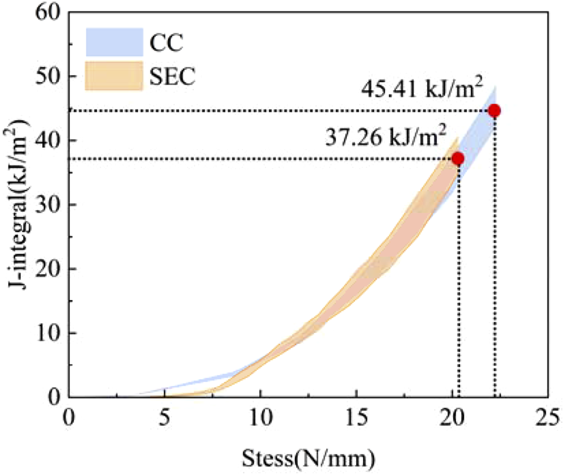
Under monotonic loading conditions, this critical J-integral can be regarded as the fracture energy of the material. At this point, the fracture energy values for the SEC and CC specimens were 45.41 kJ/m2 and 37.26 kJ/m2, respectively. The observed difference primarily arises from the higher stress concentration in the single-edge crack configuration, which accelerates damage accumulation in the cohesive zone, whereas the symmetrical crack configuration promotes a more uniform stress distribution, thereby delaying the attainment of the critical J-integral.
Figure 9 presents the relationship between the critical J-integral and the initial crack length. The critical J-integral values differ significantly between the two specimen types due to differences in crack configuration, with the SEC specimens exhibiting a critical J-integral approximately 23.9% lower than that of the CC specimens. The critical J-integral values of coated fabrics.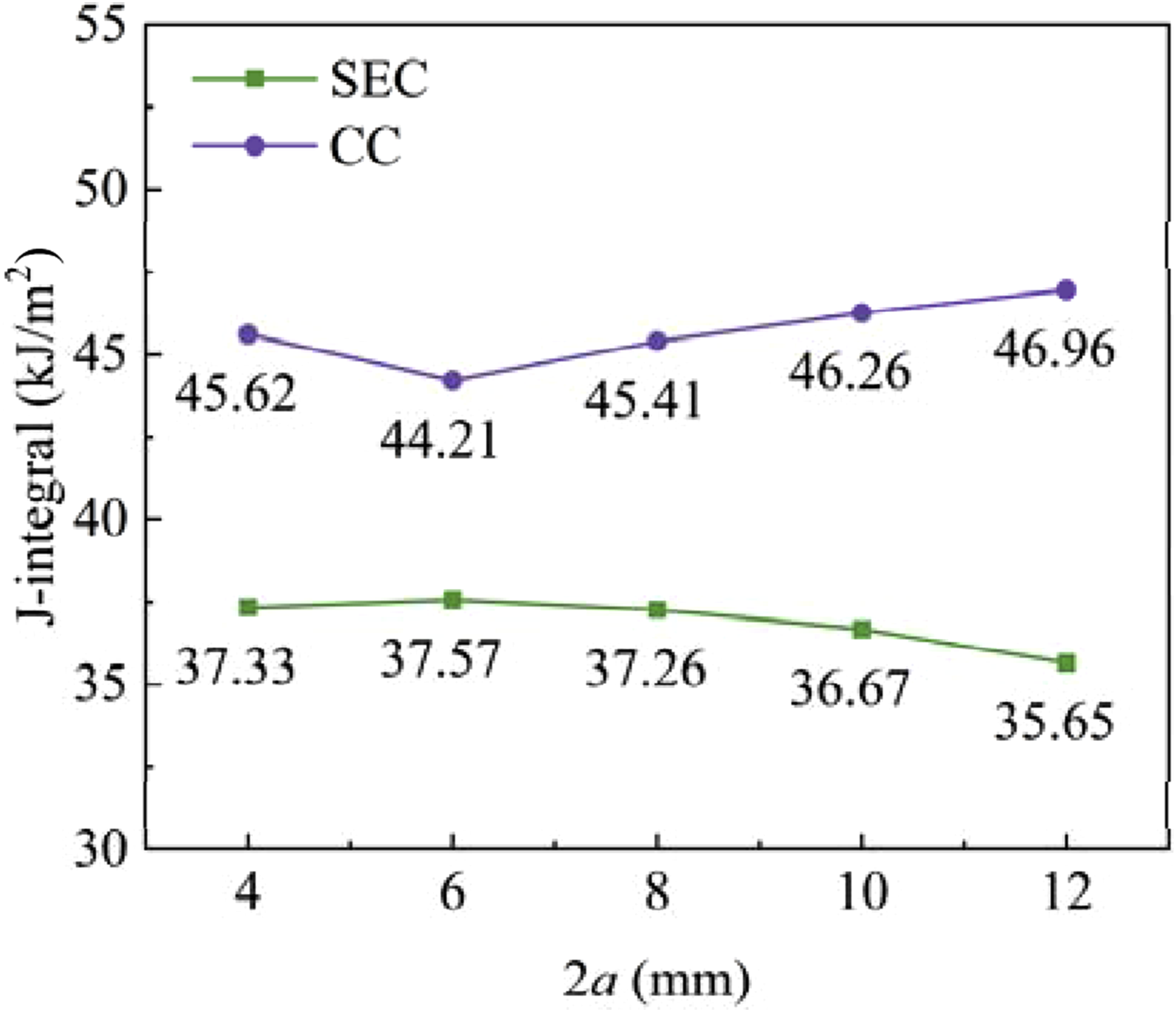
LEFM theory
30
and the Minami method
32
are two primary approaches for calculating the fracture energy of coated fabrics, both relying on theoretical assumptions or mechanical model derivations. Figure 10 compares the fracture energy measured in this study with that calculated via the LEFM theory and the Minami method. The results obtained from the LEFM theory indicate that as the crack length increases from 4 mm to 12 mm, the variation range in the warp direction rises from 35.33 N/mm to 54.48 N/mm, while the variation range in the weft direction increases from 29.29 N/mm to 52.92 N/mm. This can be attributed to the fact that the LEFM theory, centered on the linear elastic hypothesis and stress intensity factor criterion, is applicable to the small-scale yielding scenarios of homogeneous brittle materials. The fracture energy of the SEC and CC specimens. (a) SEC specimens; (b) CC specimens.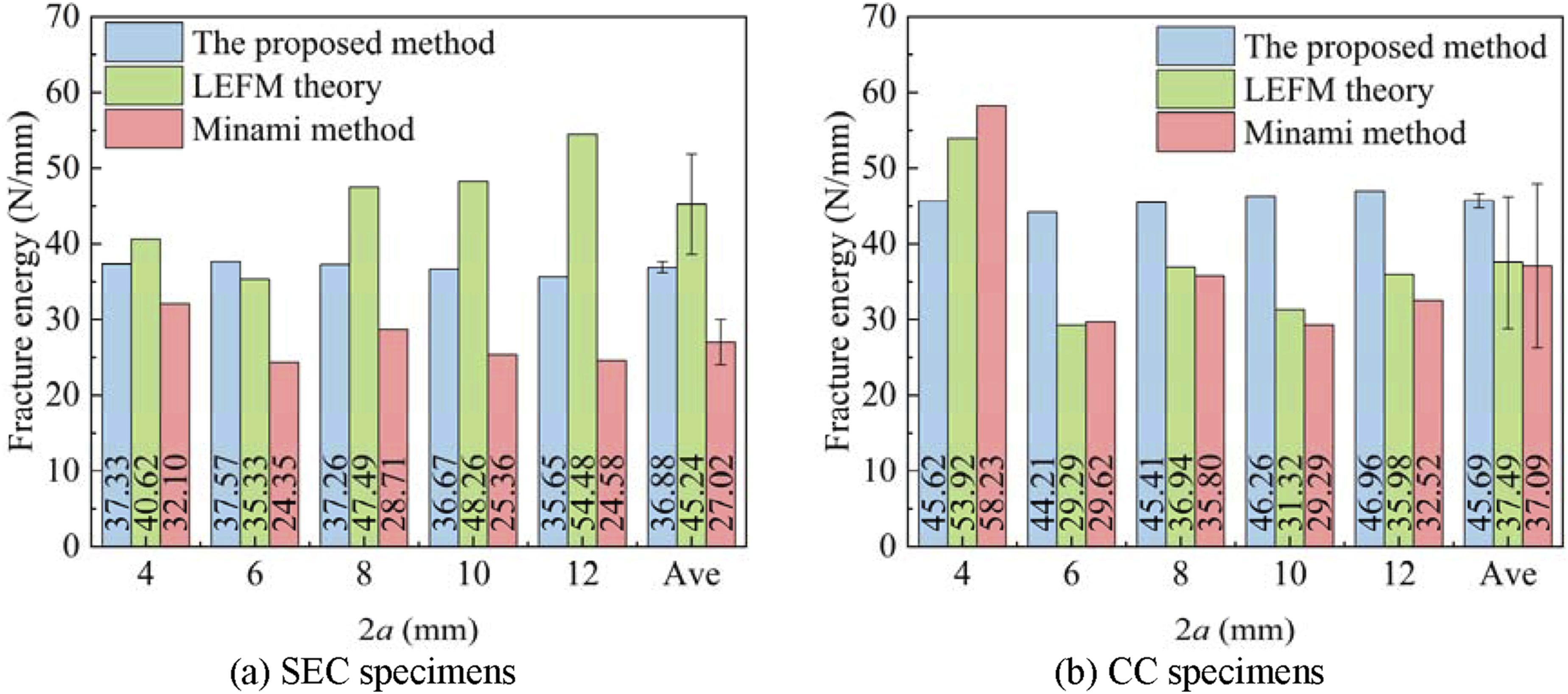
The Minami method, established based on the Hedgepeth yarn model and Griffith’s energy balance theory, calculates fracture energy by describing the interactions between yarns and energy dissipation processes. Although it incorporates the structural features of coated fabrics and exhibits relatively lower sensitivity to crack size in its calculation results, this method tends to overestimate the fracture energy in the case of small cracks (2a = 4 mm).
The fracture energy obtained through the proposed method in this work exhibits minimal influence from crack size variations. The fracture energy of both types of specimens shows no significant fluctuation with variations in the initial crack length, with the variation remaining within 6%. From the perspective of fracture mechanics, this size insensitivity fundamentally verifies that the J-integral is an intrinsic fracture property of the material.
Evaluation of CTOD
Figure 11 illustrates the evolution of the CTOD for SEC and CC specimens, with key points on the curves directly corresponding to parameters of the traction-separation law. Both specimen types exhibit a three-stage nonlinear CTOD-stress relationship. During the initial loading phase, prior to the stress reaching 8 N/mm, the CTOD of both specimen types increases gradually, with increments influenced by crack length ranging between 0.04 mm and 0.19 mm. This stage corresponds to the linear elastic deformation within the cohesive zone. As the load increases, the CTOD for both specimen types rises sharply, with increments of 0.06∼0.15 mm per 1 N/mm increase in stress. Approaching the failure stage, the growth rate of CTOD in both specimens decelerates, indicating that the cohesive zone is nearing complete separation and the crack tip opening space is approaching saturation, thereby limiting further deformation increments. Upon reaching the critical stress, the cohesive zone instantaneously separates, resulting in a sudden surge in CTOD, which signifies the fracture of the first fiber at the crack tip. Evolution of CTOD of the SEC and CC specimens. (a) SEC specimen; (b) CC specimen.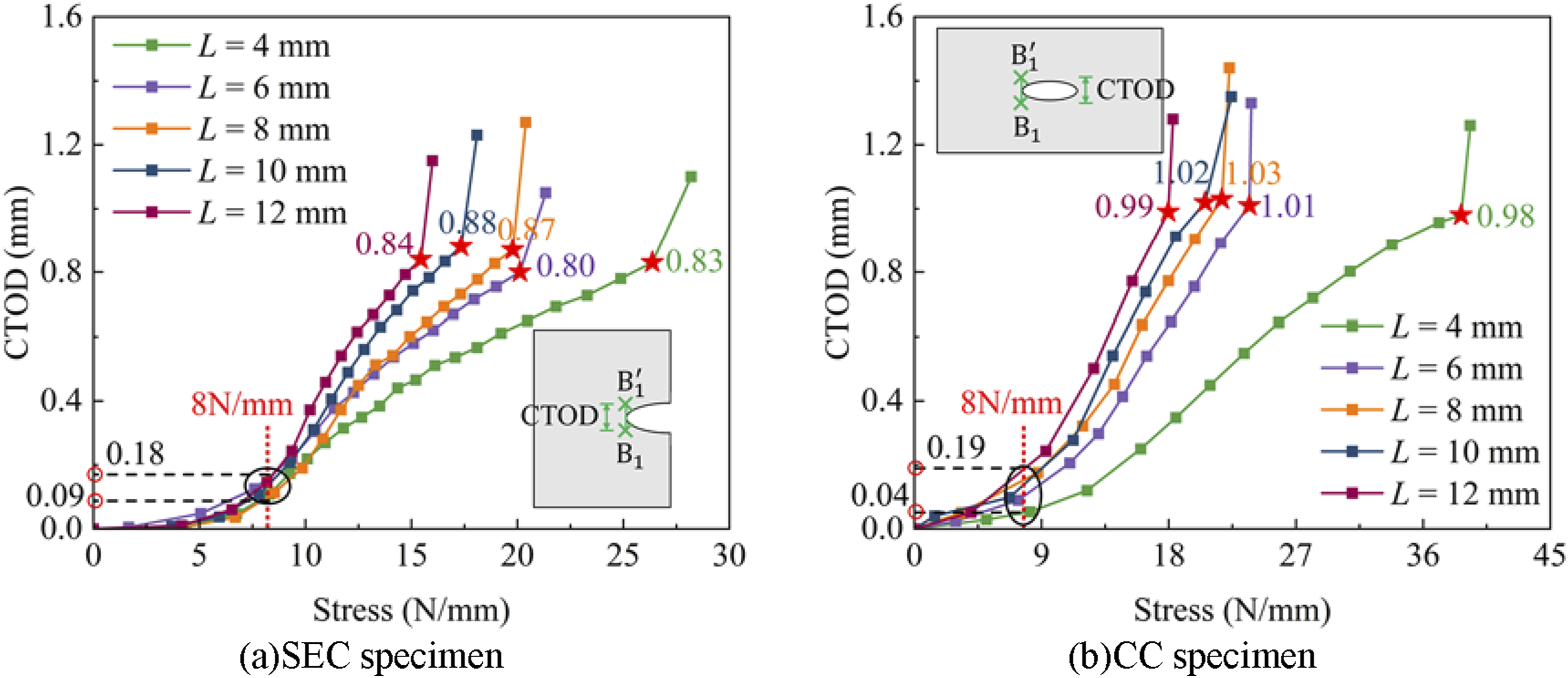
The abrupt change point in CTOD (denoted by a pentagram) represents the critical CTOD for complete separation of the cohesive zone, corresponding to the critical separation displacement in the traction-separation law. Due to the unilateral asymmetric configuration of the SEC specimens, stress concentration at the crack tip is evident. Conversely, the centrally symmetric configuration of the CC specimens results in a uniform stress distribution at both crack tips. Consequently, the increment of CTOD in CC specimens is slightly higher than that in SEC specimens under identical stress levels. Experimental measurements indicate that the average critical CTOD is 0.843 mm for SEC specimens and 1.006 mm for CC specimens.
Analysis of traction-separation law
The traction-separation law for the cohesive zones of SEC and CC specimens, constructed based on experimental data, are illustrated in Figure 12. The core parameters characterizing the elastic stage exhibit consistency across both specimen types. For SEC specimen, the The traction-separation law of the SEC and CC specimens. (a) SEC specimens; (b) CC specimens.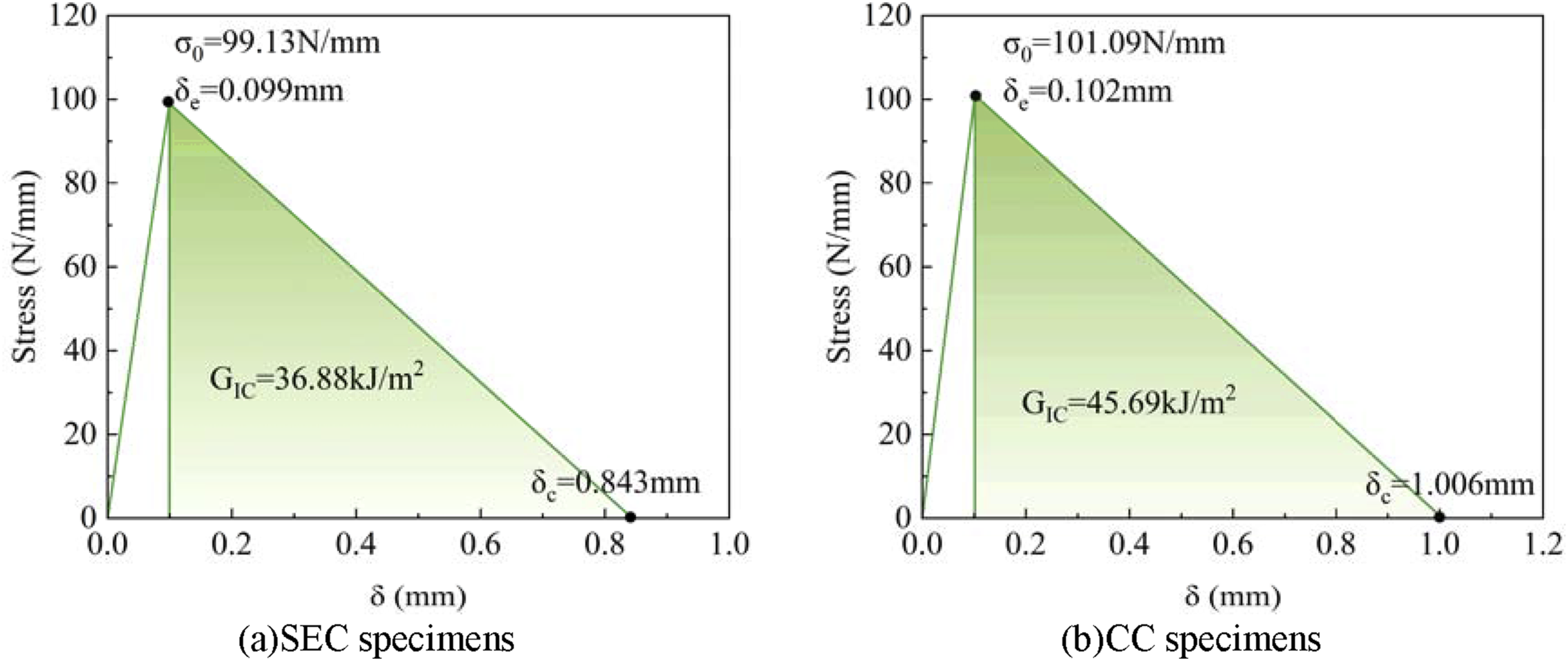
Notably, the parameters of softening stage are significantly influenced by the crack configuration. For SEC specimens, the
For the global mechanical analysis of membrane structures, the CZM parameters calibrated by CC specimens are preferred, since the crack tip stress state corresponding to these parameters is more consistent with the actual working condition of in-plane biaxial loading of membrane structures. For the tearing simulation of structures with a unilateral free boundary, the CZM parameters calibrated by SEC specimens should be adopted, which are more matched with the constraint conditions and crack tip stress state of boundary defects in engineering. For simulation scenarios under extreme load conditions, the lower limit of the two sets of parameters is recommended to ensure sufficient safety redundancy of the design scheme.
Verification of CZM parameters
To validate the reliability of the CZM parameters of coated fabrics, an automated inversion algorithm was developed based on the Isight and Abaqus platforms. The detailed procedure is illustrated in Figure 13. The Parameter inversion process based on Isight and Abaqus.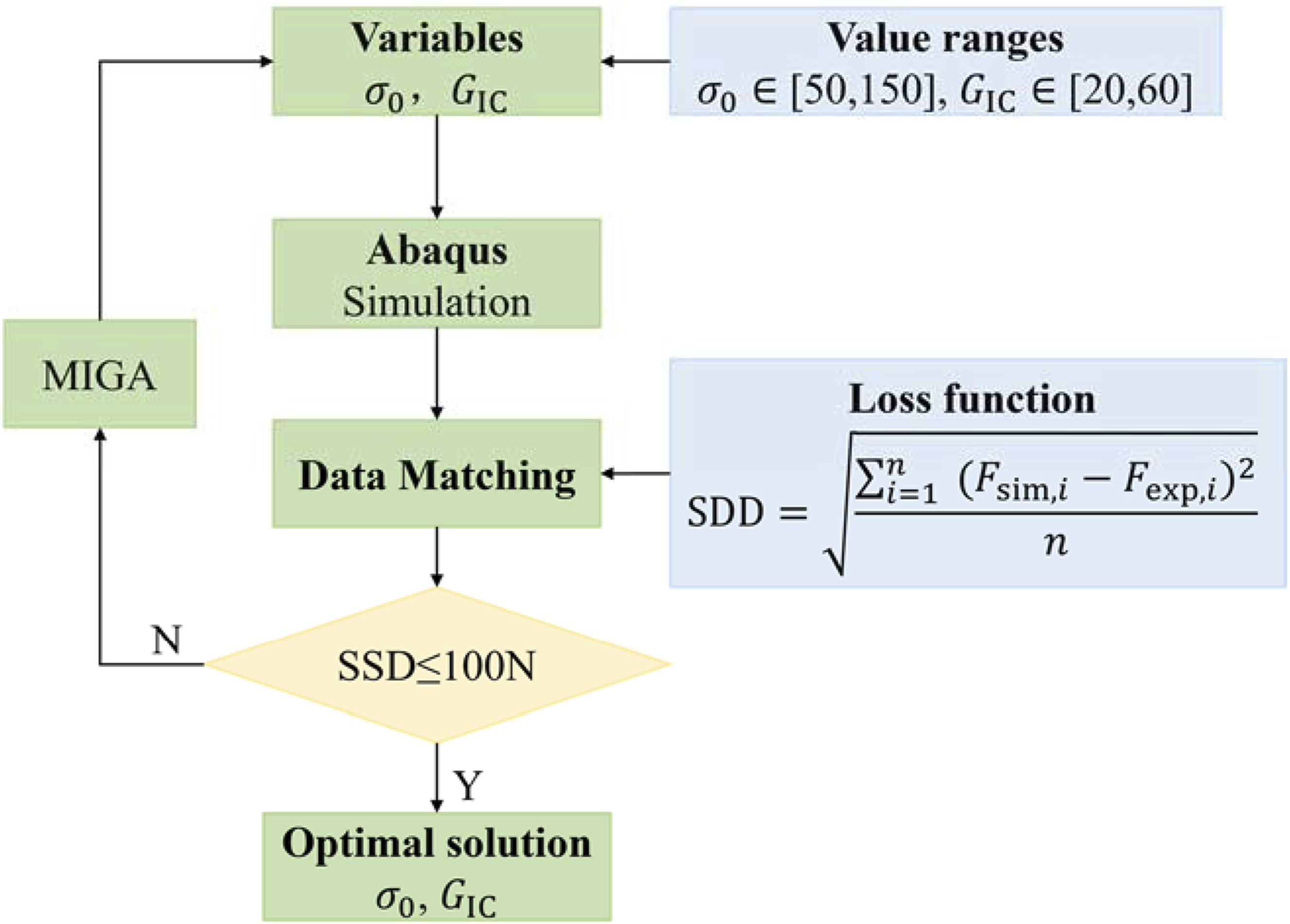
The initial design variables were input into the finite element model to initiate numerical simulation of fracture behavior and automatically extract simulated load-displacement data. Subsequently, the DataMatching module quantitatively assessed the deviation between simulated and experimental curves. If the deviation did not meet the predefined convergence criterion (SDD ≤100 N), the algorithm automatically adjusted the design variables and iteratively repeated the simulation, data extraction, and deviation comparison steps until the deviation satisfied the accuracy requirements. Ultimately, the optimal parameters were output to complete the validation process.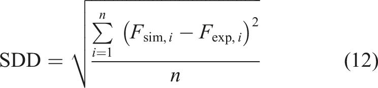
The measured values of
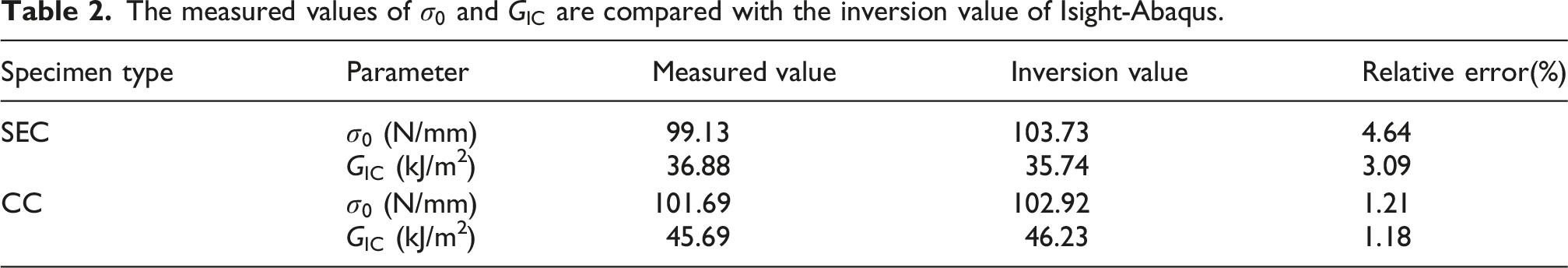
Figure 14 presents the comparison between the finite element simulation results using the CZM parameters directly measured in this paper and the experimental load-displacement curves. The quantitative error analysis shows that, for SEC specimens, the relative error of peak load from the simulation results using the measured CZM parameters is 3.46 ± 0.97%, and the relative error of the displacement corresponding to the peak load is 4.12 ± 1.48%; for CC specimens, the relative error of peak load is 2.96 ± 2.85%, and the relative error of the corresponding displacement is 5.42 ± 4.11%. Comparison of FE simulation results with experimental data. (a) SEC specimen; (b) CC specimen.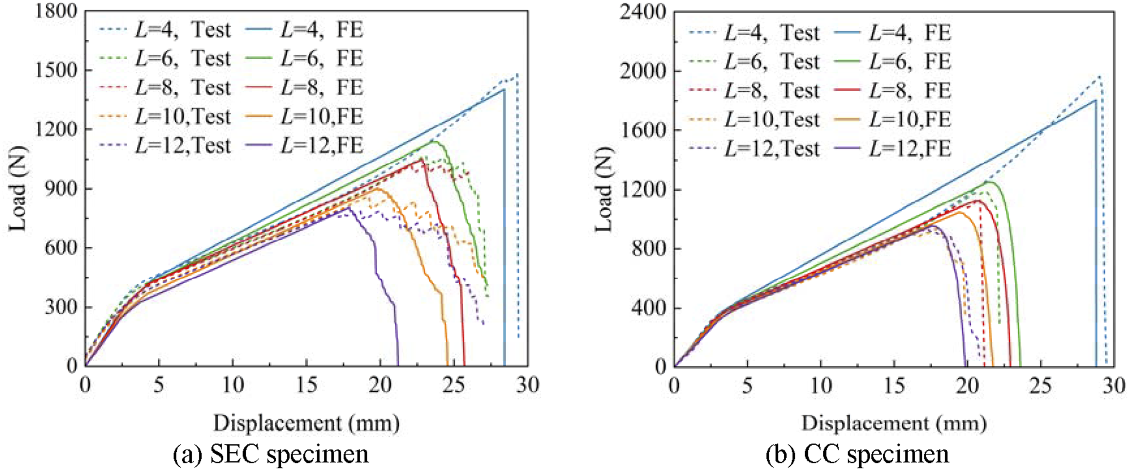
Notably, the numerical simulation based on the CZM parameters measured in this paper successfully reproduces the failure modes observed in the experiments. Specifically, for SEC specimens with a crack length of 4 mm, the simulation results show brittle fracture behavior. When the crack length exceeds 4 mm, the simulation curves present a progressive failure mode. Similarly, the transition from brittle to progressive failure mode is also captured for CC specimens in the simulation.
Conclusions
In this paper, tensile tests were carried out on two types of cracked specimens, namely SEC and CC specimens. The parameter of the bilinear CZM was determined. The accuracy of the calibrated CZM parameters was verified by the finite element inversion method, and the main conclusions are drawn as follows: (1) The DIC-based measurement method for CZM parameters of coated fabrics proposed in this paper can accurately obtain the displacement and strain distribution at the crack tip. Combined with the nonlinear J-integral calculation, the fluctuation range of the fracture energy obtained under different crack lengths is less than 6%. (2) The maximum cohesive traction and its corresponding cohesive separation displacement are inherent material properties of coated fabrics, which are slightly affected by the crack configuration, with the parameter difference between SEC and CC specimens less than 2%. In contrast, the fracture energy and critical separation displacement have a significant dependence on the crack configuration. Specifically, the fracture energy (45.69 kJ/m2) and critical separation displacement (1.006 mm) of CC specimens are higher than those of SEC specimens (36.88 kJ/m2 and 0.843 mm, respectively). (3) The relative error of peak load between the finite element simulation results using the measured parameters and the experimental results is less than 4%, and the relative error of peak displacement is less than 6%. (4) For the characterization of tearing properties of coated fabrics, it is recommended to preferentially adopt the parameters calibrated by CC specimens. For the tearing simulation of structures with boundary defects, the parameters of SEC specimens are preferred. For the conservative design of limit states, the lower limit values of the two groups of parameters are recommended.
Footnotes
Funding
The authors disclosed receipt of the following financial support for the research, authorship, and/or publication of this article: This work was supported by the National Natural Science Foundation of China (No.52278229, 52308222, 52378180), the Natural Science Foundation of Sichuan Province (No. 2024NSFSC0165), and the Qinglan Project of Jiangsu Province of China (2024).
Declaration of conflicting interests
The authors declared no potential conflicts of interest with respect to the research, authorship, and/or publication of this article.
Data Availability Statement
Some or all data, models, or codes generated or used during the study are available from the corresponding author by request (for research and teaching).