
Abstract
Accurate prediction of lightning strike damage in composite laminates remains challenging due to oversimplified representations of current distribution and through-thickness conductivity. This study introduces a novel model that uniquely integrates an elliptical Gaussian current distribution to capture both arc expansion and non-uniform current density, and explicit representation of Interlayer resin enrichment with dielectric breakdown properties. Quantitatively, compared to the conventional uniform current model, the proposed elliptical Gaussian distribution alone reduces damage depth prediction error by 66.7% (reducing under-prediction from 3 plies to 1 ply). Crucially, further incorporating explicit interlayer modeling reduces the depth error by nearly 100%, achieving exact prediction of 5-ply damage as validated by experiment, while maintaining total Joule energy variation within 1% of the Gaussian-only model. Furthermore, unlike previous models that require subsequent mechanical analysis to predict delamination, this approach uniquely captures both in-plane ablation and interlayer delamination morphology directly from coupled thermal-electrical analysis. These findings demonstrate that explicitly modeling elliptical Gaussian current distribution and interlayer resin enrichment is not merely incremental but essential for accurate lightning strike damage prediction in composite laminates.
Keywords
Introduction
Epoxy-based composite materials are extensively used in aerospace, wind power, and other industries due to their excellent mechanical properties, such as high strength-to-weight and stiffness-to-weight ratios. The damage behavior of fiber-reinforced polymer composites has been widely investigated under various conditions, including mechanical loading,1–3 environmental aging,4–6 and manufacturing processes.7–9 Recently, damage to carbon fiber composites under lightning strike conditions is also attracting increasing attention. Poor electrical conductivity makes them highly susceptible to severe damage from lightning strikes. The resulting ablation and delamination can significantly reduce the structure’s residual strength, potentially leading to major safety hazards. The damage process of composite materials under lightning strikes involves intricate interactions among multiple physical fields, including electrical, thermal, chemical, magnetic, and mechanical forces. In recent years, researchers have conducted extensive studies on the lightning strike damage characteristics10–19 and relevant protection strategies20–26 for composite materials. The research results indicate that material conductivity and arc channel expansion behavior have a significant impact on the lightning strike damage of composite materials.
Numerical simulations have emerged as a critical tool for studying lightning strike damage in composite materials. However, debate persists regarding the modeling of conductivity behavior in the thickness direction of materials. Numerous studies assume that the conductivity of carbon fiber-reinforced composites under lightning strike conditions depends on temperature,27,28 pyrolysis degree,29,30 and even potential gradient,31–33 though these assumptions have not been effectively verified by experiments. Sun et al.34,35 demonstrated that out-of-plane conductivity increases with increasing current. Fujisawa et al. 36 measured the electrical conductivity of laminate with interleaf resin layers under high impulse current and obtained the breakdown strength, thereby clarifying that mechanism of the increased conductivity was regarded as the irreversible breakdown in interleaf resin layers and interfaces between fiber and resin. In fact, the conductivity in the thickness direction of composites for conventional applications is usually much lower than that in the in-plane direction. 13 This is because resins tend to accumulate at the interlayers during the manufacturing process. The resin-rich regions typically exhibit lower electrical conductivity compared to fiber-rich regions, and this may lead to non-uniform damage distribution across the laminate. Previous numerical simulation studies27,30,36 adopted a homogenization assumption without accounting for resin enrichment at the interlayer. Consequently, the effect of interlayer resin enrichment on lightning strike damage in laminates has not been fully elucidated.
Existing studies on lightning arc behavior during lightning strikes on composites reveal inconsistent assumptions and unresolved modeling challenges. Early researchers applied the lightning strike current either to a single node27,37 or uniformly over a fixed-radius area.29,38,39 While some assume circular arc root expansion40,41 or a triangular arc shape per magnetohydrodynamic (MHD) analysis, 42 experiments show elliptical expansion with greater spread perpendicular to fibers.36,43,44 The expansion mode significantly affects damage morphology, 45 and comparisons between circular and elliptical models confirm that arc shape critically influences electrical, thermal, and mechanical responses. 46 The expansion of the arc channel is usually accompanied by a change in current density. The distribution of current density during lightning arc channel expansion remains contested, ranging from uniform 46 to non-uniform assumptions.30,45 Perera et al. 47 used image analysis to demonstrate that current density follows a Gaussian distribution within a 30 cm arc channel. Millen et al.48,49 identified non-uniform distribution of lightning current through MHD and established a circular, non-uniform distribution current loading model. Fujisawa et al. 36 observed the elliptical expansion characteristics of lightning current through direct lightning strike tests but still assumed a uniform current distribution when developing the numerical model, and this discrepancy may explain why the damage depth predicted by the numerical simulation is significantly lower than experiment. Sontakkey et al.50,51 assumed that the arc radius perpendicular to the fiber direction is three times that parallel to the fiber direction to achieve elliptical expansion of the arc channel. However, this assumption is inconsistent with existing experimental results. 36 To date, a model that successfully integrates both the elliptical expansion of the arc channel and the non-uniform distribution of current density remains elusive. Neglecting the elliptical nature of the arc channel or the non-uniformity of current density could result in oversimplified models that underestimate damage at critical parameters, particularly in regions where the current density is highest.
In summary, previous numerical models for lightning strike damage in composites exhibit two major gaps: (1) oversimplified current distribution, either circular uniform29,38,39 circular Gaussian,30,40,41 or elliptical but uniform,36,46 that fails to capture the experimentally observed elliptical Gaussian characteristics36,47; and (2) the neglect of interlayer resin enrichment and the subsequent homogenization of through-thickness conductivity.27,28,29,30,37,38,39,52,53,54,55 The present study bridges these gaps by developing a novel model that uniquely integrates an elliptical Gaussian current distribution capturing both arc expansion and non-uniform current density, and explicit interlayer representation with dielectric breakdown properties derived from series-resistance principles. The proposed model not only improves the accuracy of through-thickness damage prediction but also simultaneously predicts intralayer ablation and interlayer delamination within a single coupled thermal-electrical analysis, eliminating the need for subsequent thermo-mechanical coupling simulations. By comprehensively analyzing the impacts of current distribution and interlayer resin enrichment, this research is expected to advance the application of high-fidelity numerical tools for predicting lightning strike failure in laminated composite materials.
Arc root expansion and current density distribution
The Gaussian distribution model proposed by Dong et al.
30
is appropriate for cases where the arc root exhibits circular expansion, whereas the elliptical expansion model proposed by Foster et al.
45
is more suitable for cases with uniform current density distribution. However, experimental results confirm that arc channels exhibit elliptical expansion on the surface of laminated plates36,43,44 and that lightning current density can be characterized by a Gaussian function.
47
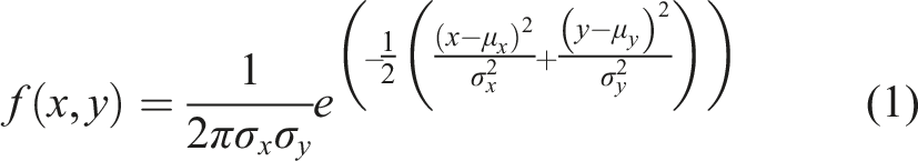
To address this issue, it is assumed that the current follows a two-dimensional Gaussian function, and the current density factor can be expressed as equation (1).
56
The current density factor is used to describe the distribution coefficient of current density on the material surface. Multiplying the total current by this factor yields the current density. The integral of this distribution function over the entire domain is equal to 1, which satisfies the principle of current conservation. When
When considering an elliptically expanding arc root, assuming that the distribution of current density on the surface of the laminate follows a Gaussian function, the primary challenge lies in determining the distribution parameters. According to the properties of Gaussian functions defined in equation (1), the integral of the function over the entire domain is equal to 1. The Gaussian distribution also adheres to the 3-sigma rule, meaning that 99.74% of the values fall within the 3-sigma range. Therefore, the radius of the lightning current measured from experimental results at any given time can be considered as 3-sigma value, which ensures that over 99% of the current is confined within this region, leading to a convergent distribution on the laminate surface. Based on these assumptions, the distribution parameters can be effectively estimated. Using this model, the calculated distribution of current density factor is presented in Figure 1. The elliptical Gaussian distribution model proposed in this study enables rapid convergence of current density within the 3-sigma range. Distribution of current density factor in this study (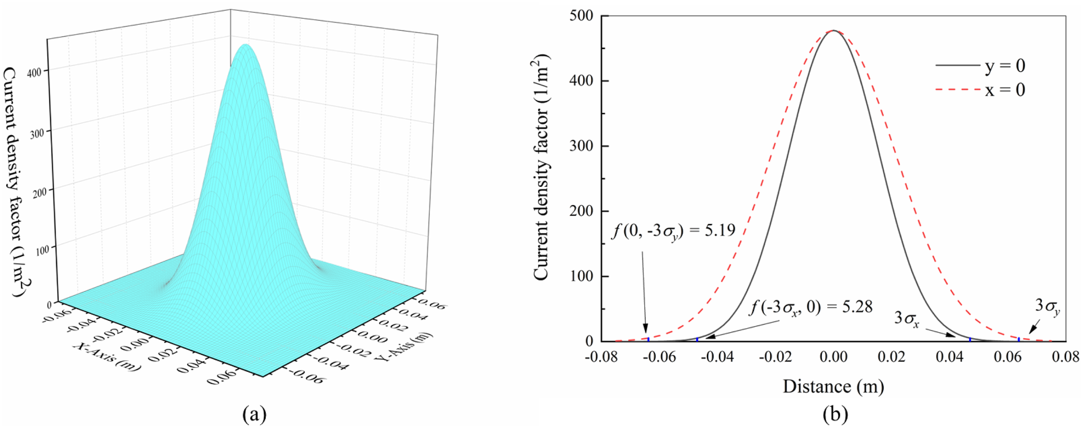
Electrical properties of interlayer resin
In this study, the term “interlayer” is used to denote the resin-rich region explicitly modeled between adjacent plies (intralayer) in the finite element framework. This encompasses both purposely inserted toughening layers (often termed “interleaf” layers in the literature) and the resin-rich zones inherently formed during standard laminate fabrication. The T800/3900-2B material system studied in Ref. 36, which contains a distinct toughening interleaf, serves as a specific and critical case where such an interlayer region dominates the through-thickness electrical response. Our modeling approach, by focusing on the generalized “interlayer” concept, aims to capture the essential physics of these resin-dominated zones that control dielectric breakdown, irrespective of their specific manufacturing origin.
Due to the poor conductivity of epoxy resin, the electrical conductivity in the thickness direction of laminates is significantly lower than that in the transverse direction. Fujisawa et al. 36 developed a specialized fixture to perform low-pulse current lightning strike tests on composite laminates, Thus, successfully determined the dielectric breakdown critical voltage and the post-breakdown conductivity of the laminate in the thickness direction.
Consider a composite laminate with n intralayer to withstand strong current from outside the surface, as depicted in Figure 2(a). In the coupled thermal-electrical analysis of composite materials subjected to lightning strikes, the transient effects of current are usually ignored.
57
Although Fujisawa et al.
36
observed the influence of capacitive and inductive effects on the voltage-current relationship of the material, they did not explicitly consider these effects when constructing the conductivity-potential gradient relationship. Instead, they treated the composite as a purely resistive circuit, thereby implicitly embedding the capacitive and inductive effects within the conductivity-potential gradient relationship. Therefore, the current conductivity-potential gradient relationship represents only the macroscopic electrical properties of the material. The influence of inductive and capacitive effects on the current and voltage distribution within the laminate remains to be further investigated. Under this assumption, both the intralayer and interlayer regions can be effectively modeled as a series of pure resistors, as shown in Figure 2(b). Since the intralayer is transversely isotropic, its conductivity is the same in both transverse and thickness directions. According to the experiments conducted by Fujisawa et al.,
36
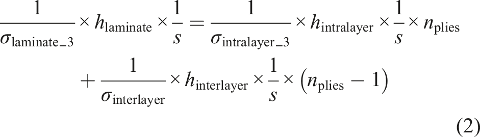
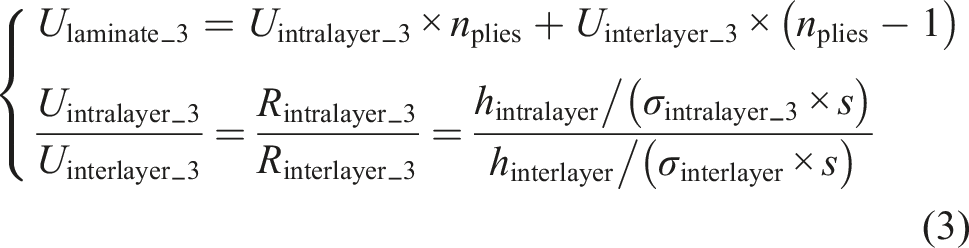
the electrical conductivity of the intralayer, which has a high fiber volume fraction, is not influenced by the high voltage of lightning strikes; thus, there is no need to consider dielectric breakdown between fibers. In contrast, the interlayer undergoes dielectric breakdown under high voltage, leading to changes in the conductivity of the laminate under lightning current. The schematic diagram of interlayer dielectric breakdown is presented in Figure 2(c). The geometric parameters, conductivities in the transverse and thickness directions, and the breakdown voltage in the thickness direction of the laminate can be obtained through experimentation. Based on the principles of series resistance (equation (2) and equation (3)), the electrical conductivity and dielectric breakdown voltage of the interlayer can be determined. Equivalent circuit and electrical breakdown diagram of composite materials in the thickness direction: (a) Laminate model; (b) Equivalent circuit model of laminate; (c) Interlayer dielectric breakdown.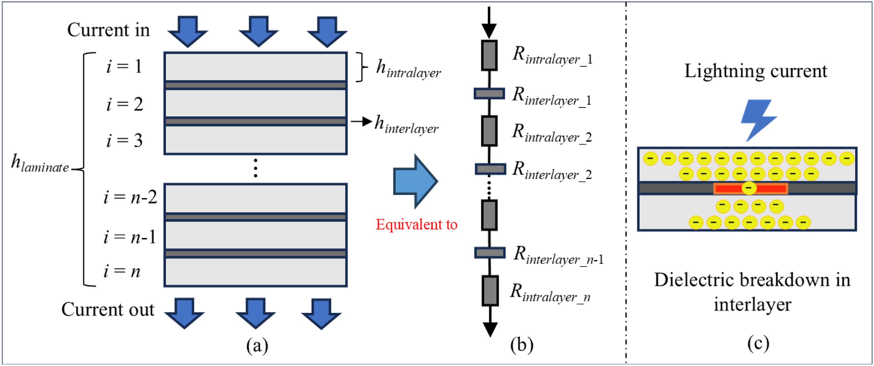
Numerical modeling of composite laminates subjected to lightning strikes
The research framework of this study was shown in Figure 3. The flowchart illustrates three main components: (1) model inputs derived from experimental data
36
; (2) three comparative cases (Cases 1–3) with different current distribution and interlayer modeling methods; and (3) post-analysis validation against experimental results. Flowchart of the numerical modeling framework.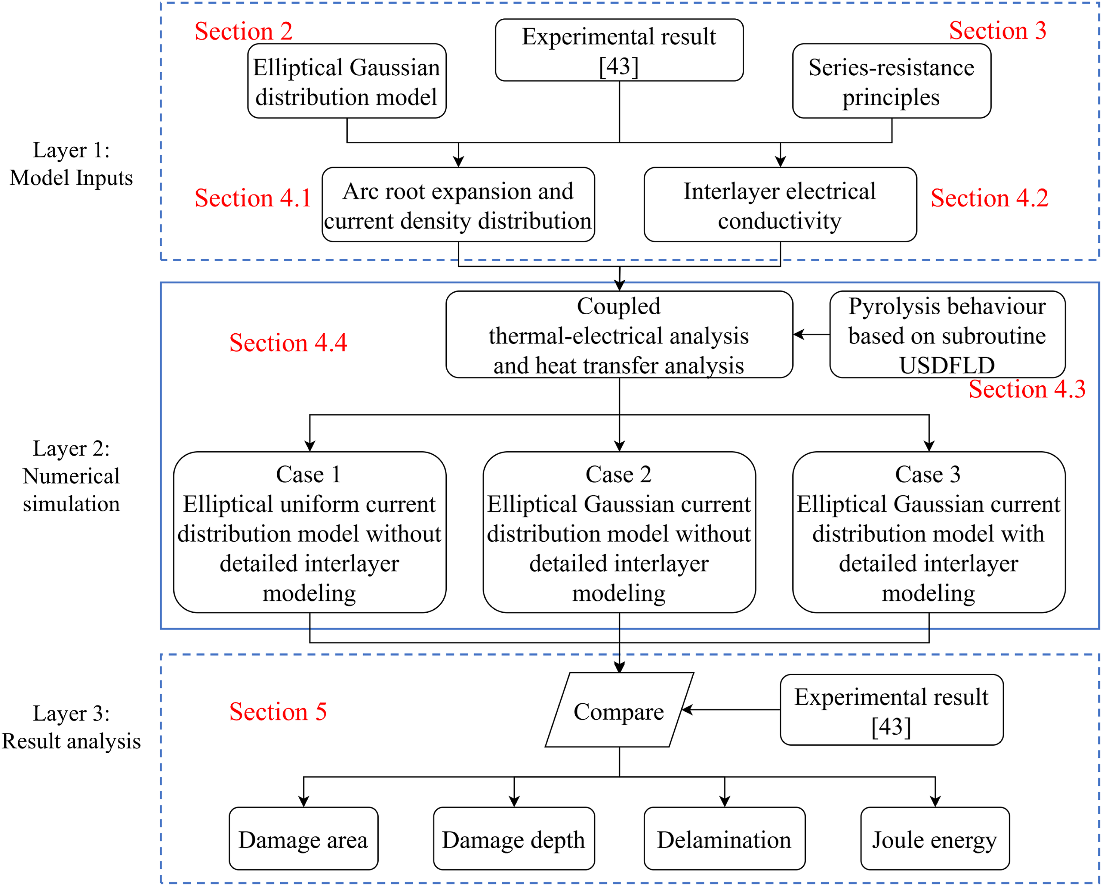
Modeling of arc root expansion and current density distribution behavior
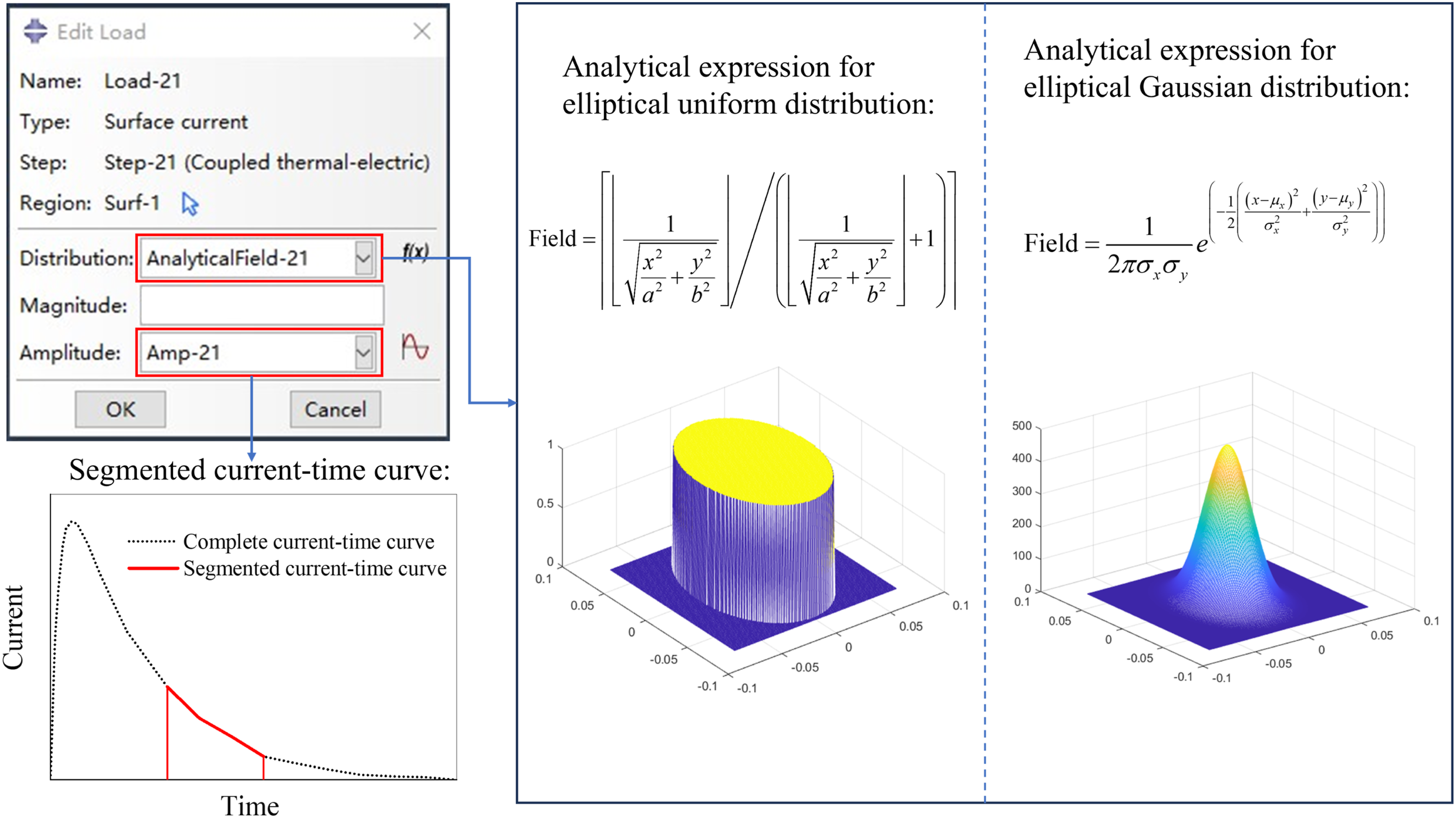
Foster et al.
45
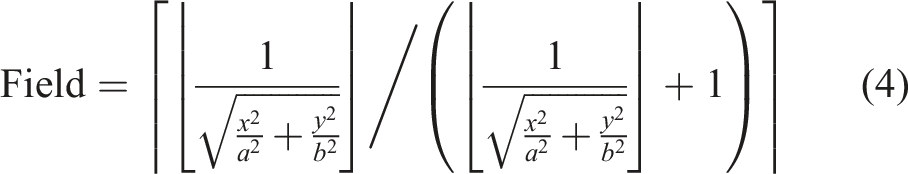
proposed a method for modeling arc channel expansion with a uniform current distribution on the surface of laminates. The complete current loading process is divided into several analysis steps, with a customized current distribution expression applied at each step (as shown in equation (4)). When the center of the element is within the arc channel, the expression value is set to 1, while it is set to 0 when outside the arc channel, thereby achieving an elliptical expansion of the arc channel with a uniform current distribution. Fujisawa et al.
36
adopted the method proposed by Foster et al.
45
to simulate the elliptical expansion of the electric arc on the surface of carbon fiber composite laminates. Due to a lack of direct experimental data support and effective characterization methods, the current was assumed to be uniformly distributed over the laminate surface. The method proposed in Section 2 is adopted to achieve both elliptical arc channel expansion and Gaussian current density distribution on the laminate in the present study.
The lightning current application process is divided into 21 analysis steps in the numerical simulation analysis. In each step, the radius of the arc channel remains constant and is set to the arc channel radius corresponding to the end time of that step, as illustrated in Figure 4. Figure 5 illustrates the implementation for arc channel expansion and current distribution. In each analysis step, the shape of the arc channel and current distribution characteristics are defined using a field equation. For more detailed information, refer to Foster et al.
45
Arc root radius in transverse and fiber directions. Data from Fujisawa et al. are included for Ref. 36. The implementation of the arc expansion and current distribution.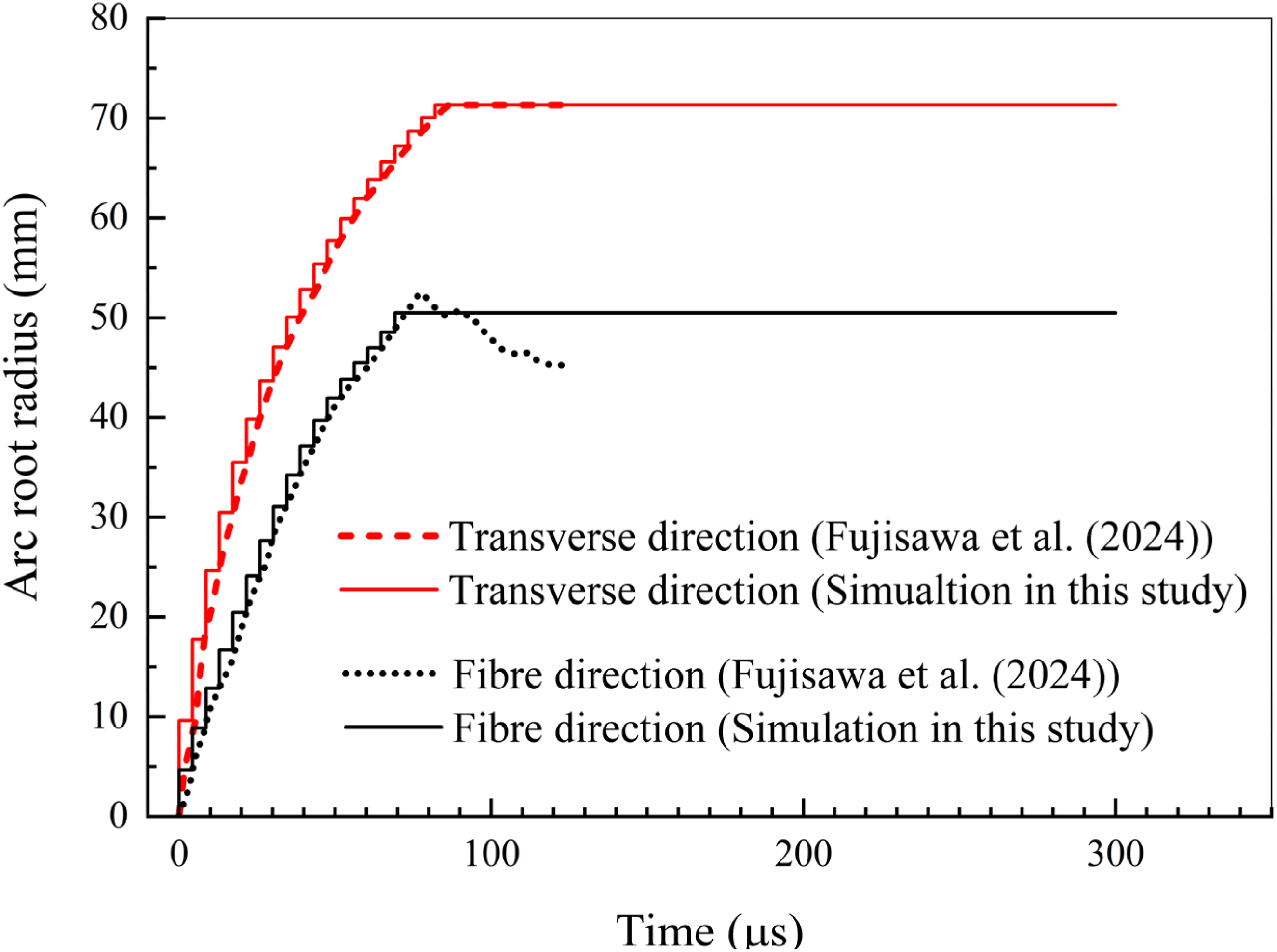
The experiment conducted by Fujisawa et al.
36
observed that the arc channel expanded along both the fiber direction (45°) and the transverse direction (−45°). However, neither equation (1) nor equation (4) account for the fiber layup angle. To address this, a right-handed Cartesian coordinate system is defined as the reference system for the analytical expression of current distribution, with the X-axis aligned along the fiber direction and the Y-axis perpendicular to it. Figure 6 shows the current distribution on the laminate surface obtained using the methods proposed in Section 2 and by Foster et al.
45
The elliptical Gaussian distribution model proposed in Section 2 disperses the current across the entire laminate surface, with greater concentration in the central region. In contrast, the model proposed by Foster et al.
45
restrict the current to an elliptical region with a uniform distribution within that region. Current distribution at time 82.06 μs: (a) Elliptical Gaussian distribution; (b) Elliptical uniform distribution.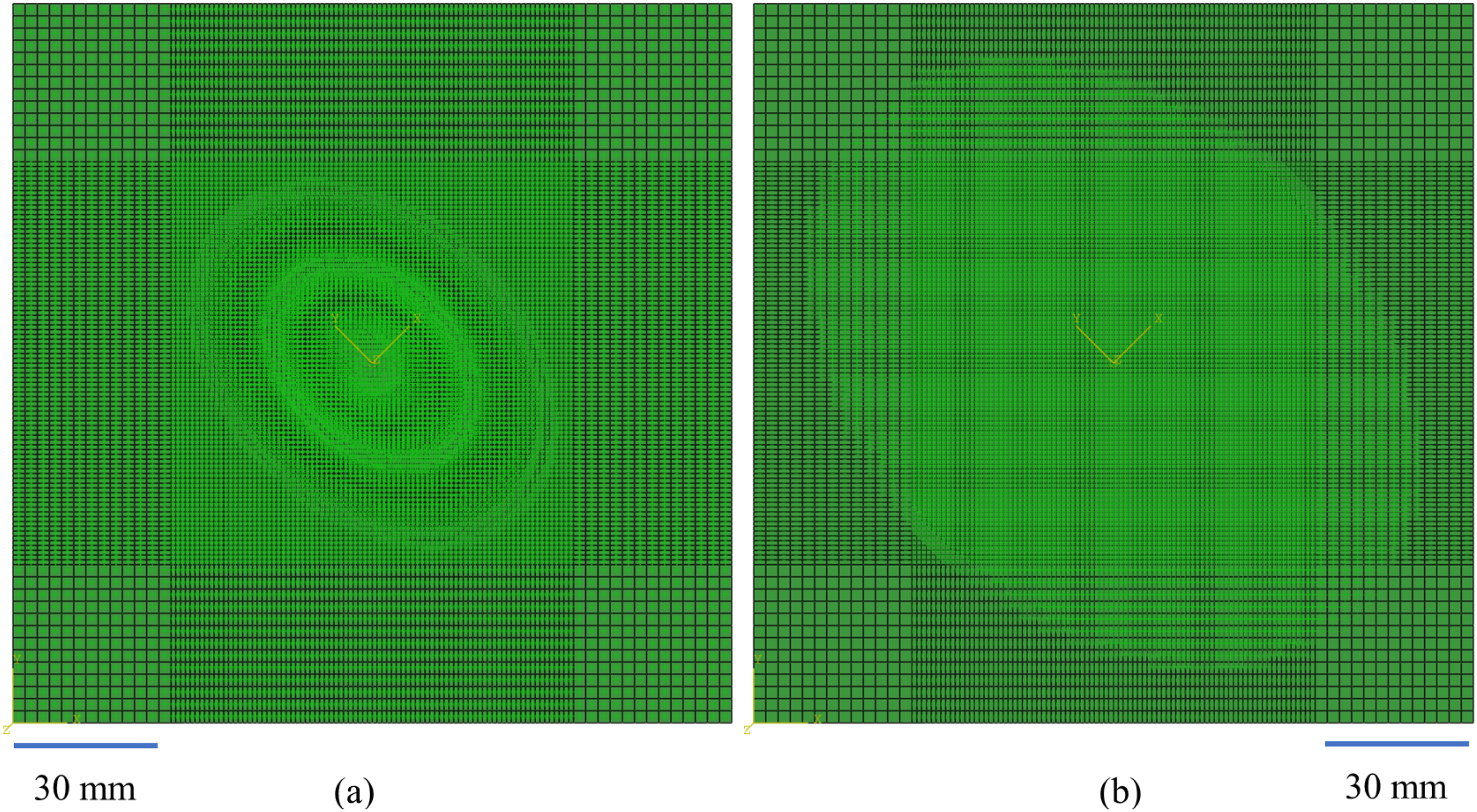
Modeling of interlayer electrical conductivity
Material properties of specimens 36 .
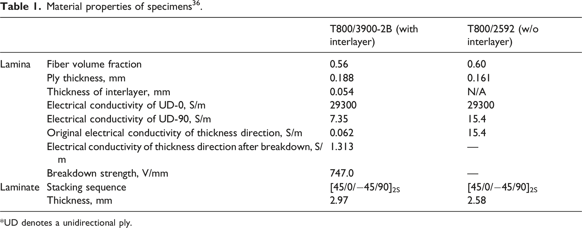
*UD denotes a unidirectional ply.
The interlayer conductivity and voltage calculation method proposed in Section 3 were employed to analyze the raw data provided by Fujisawa et al.
36
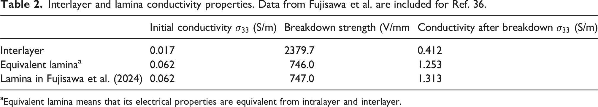
Based on the algorithm proposed in Section 3, the linear relationship between conductivity and potential gradient of the interlayer is illustrated in Figure 7(a), and the electrical properties of the equivalent lamina are shown in Figure 7(b). The electrical properties of the equivalent lamina derived from the fitted interlayer conductivity parameters align with the experimental results, thus validating the method proposed in Section 3. The conductivity properties of the interlayer and lamina are summarized in Table 2. Using the method proposed in this study, the relationship between interlayer conductivity and the electric potential gradient can be determined, which in turn supports refined modeling with separate treatment of intralayer and interlayer properties. Curve of conductivity and applied voltage: (a) Interlayer; (b) Equivalent lamina. Data from Fujisawa et al. are included for Ref. 36. Interlayer and lamina conductivity properties. Data from Fujisawa et al. are included for Ref. 36. aEquivalent lamina means that its electrical properties are equivalent from intralayer and interlayer.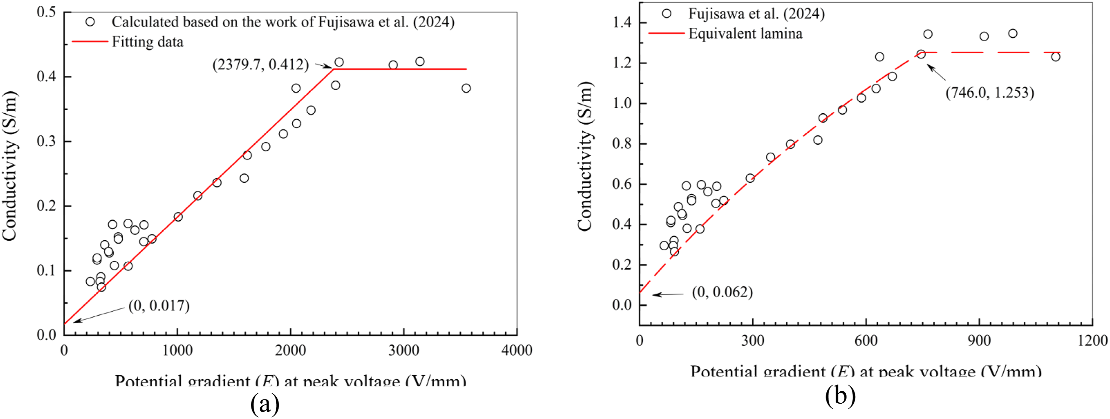
Modeling of pyrolysis behavior
Under the action of Joule heating, the resin undergoes thermal decomposition, resulting in matrix cracking and interlayer delamination. The thermal decomposition of the matrix can be expressed using the degree of pyrolysis 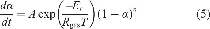
Considering the nonlinear heating effect during lightning strikes, Xiao et al.
59
proposed a predictive model for pyrolysis degree under nonlinear heating conditions, which are summarized as follows: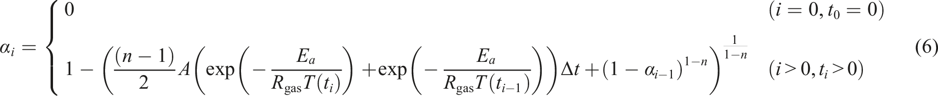
where the subscripts
Kamiyama et al. 37 confirmed that when the pyrolysis degree exceeds 0.1, interlayer resin loss induces delamination. Based on this finding, Fujisawa et al. 36 adopted a pyrolysis degree of 0.1 as a threshold to evaluate delamination damage in laminates. They also reduced the thermal conductivity in the thickness direction to one-hundredth of its original value once the pyrolysis degree surpassed 0.1. Considering that delamination creates an air gap between the intralayer, the thermal conductivity of the layer in the thickness direction was further adjusted to match that of air in this study, that is, 0.026 W/(m·K), 60 when the pyrolysis degree reached 0.1.
Fujisawa et al.
36
assumed that when the material’s pyrolysis degree reaches 1, its electrical conductivity in the thickness direction increases to a certain value of
FEM models and boundary conditions
The geometry and boundary conditions corresponding to Fujisawa et al.
36
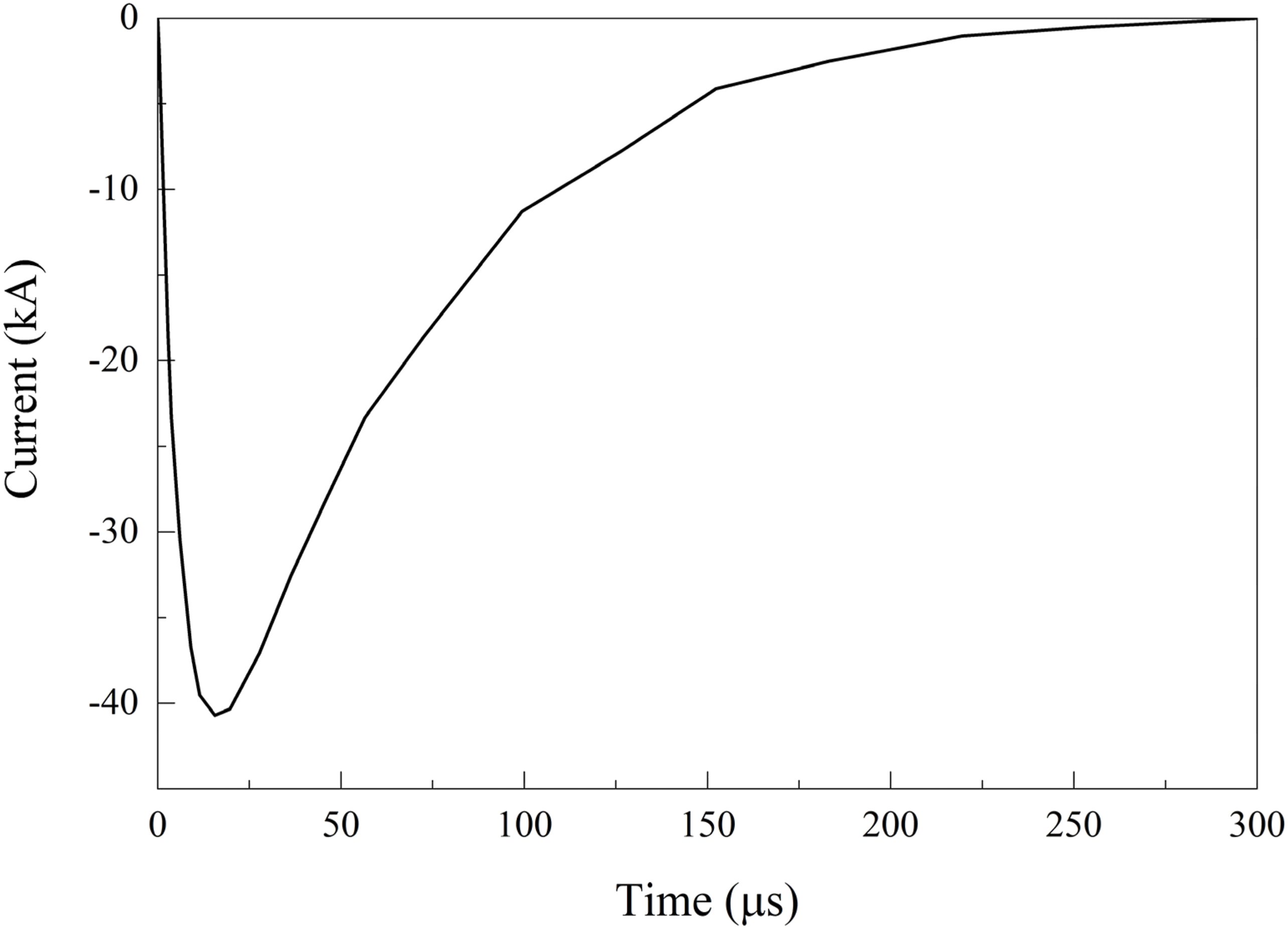
were illustrated in Figure 8. The specimen measures 150 mm in length, 150 mm in width and 3 mm in height. The composite laminates consist of 16-ply ([45/0/−45/90]2S). The composite laminates were simulated using 8-node three-dimensional coupled thermal-electrical element (DC3D8E) in ABAQUS. The size of grid in the central area of the numerical model is 1 mm, and the edge area is 2.5 mm. The edges and bottom of the finite element model were grounded, while surface radiation and convection were applied to the top surface. Lightning current (component A with peak current of −40.0 kA, as shown in Figure 9) was applied to the central area of the finite element model using surface current method. Coupled thermal-electrical analysis was employed to simulate the current loading process, with a total simulation time of 300 μs. Following it, a pure heat transfer analysis was conducted with a total simulation time of 30 s. Considering carbon fibers sublimate at approximately 3316°C, and to restrict the maximum temperature of the element, a virtual latent heat was incorporated into the simulation. Because temperature is reversible, the element’s temperature gradually decreases during the heat transfer analysis. Therefore, the UVARM subroutine was employed to log the highest temperature attained by the elements throughout the entire analysis. The pyrolysis behavior of the material was captured using the USDFLD subroutine. Geometry and boundary conditions for numerical simulation model. Current Waveforms of component A (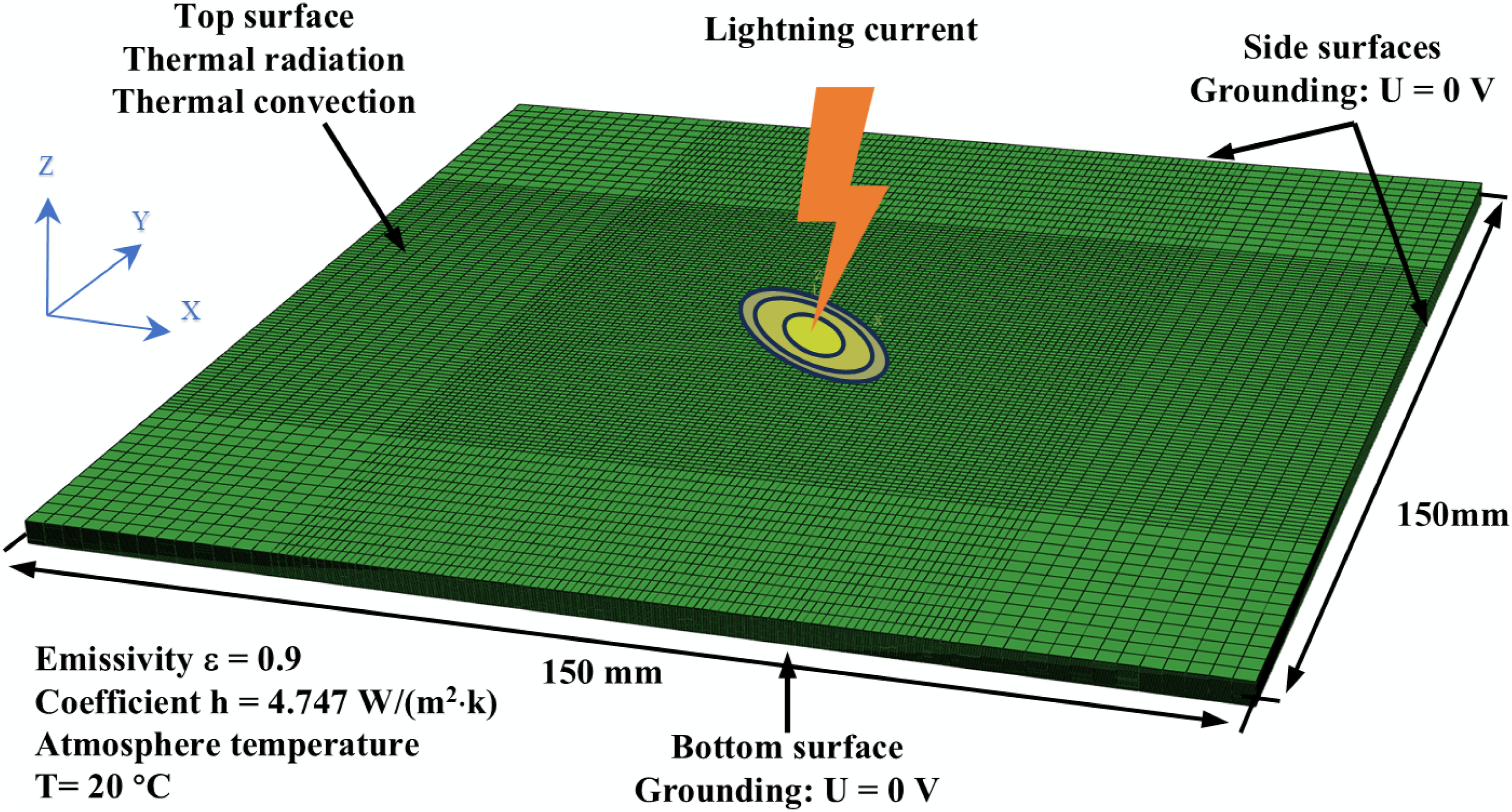
To investigate the impact of Gaussian current distribution and interlayer resin enrichment on lightning strike damage in composite materials, three simulation cases were established: Case 1, an elliptical uniform current distribution model without detailed interlayer modeling, as shown in Figure 10(a). This model is consistent with Fujisawa et al.
36
; Case 2, an elliptical Gaussian current distribution model without detailed interlayer modeling; Case 3, an elliptical Gaussian current distribution model with detailed interlayer modeling, thereby accounting for interlayer resin enrichment, as shown in Figure 10(b). In all three cases, the arc channels exhibit elliptical expansion, consistent with experimental results.
36
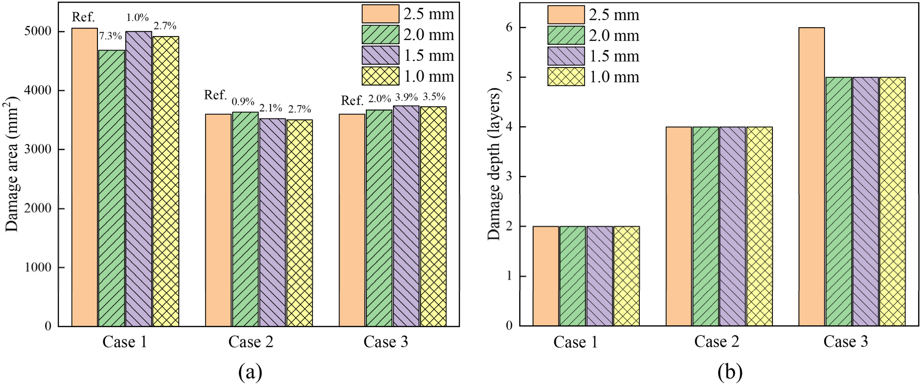
The mesh size convergence has been verified, as shown in Figure 11. Modeling of the thickness direction of laminate: (a) Without detailed modeling of interlayer; (b) With detailed modeling of interlayer. The mesh size convergence analysis: (a) damage area; (b) damage depth.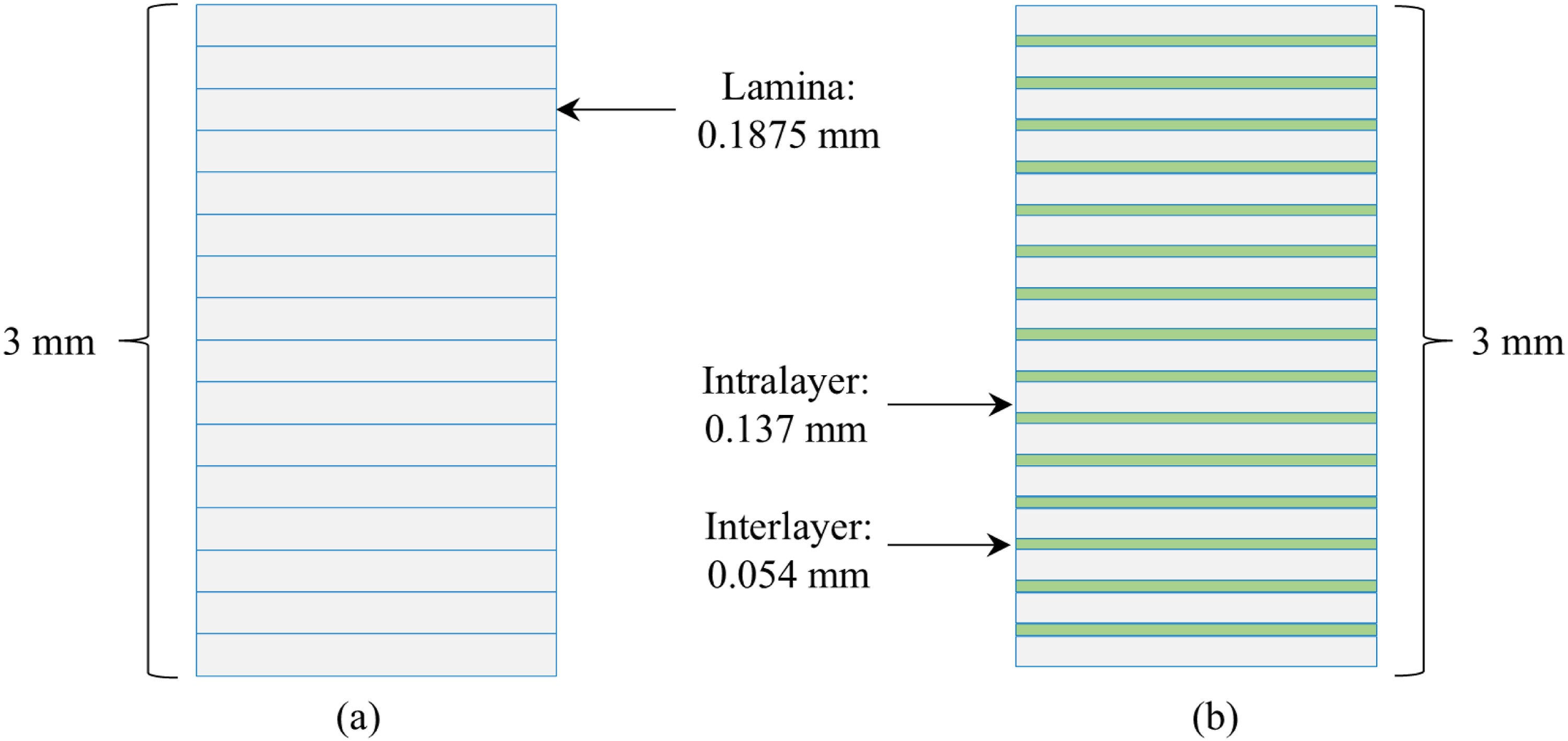
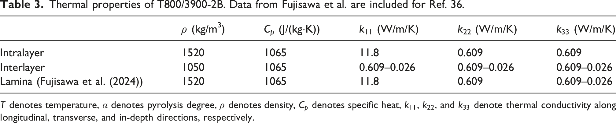
Thermal properties of T800/3900-2B. Data from Fujisawa et al. are included for Ref. 36.
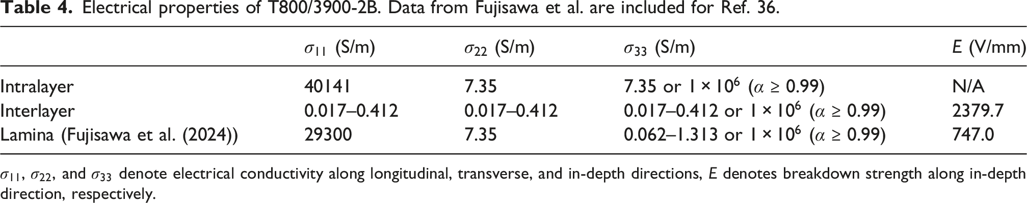
Electrical properties of T800/3900-2B. Data from Fujisawa et al. are included for Ref. 36.
Results and discussion
Effect of elliptical Gaussian distribution of current
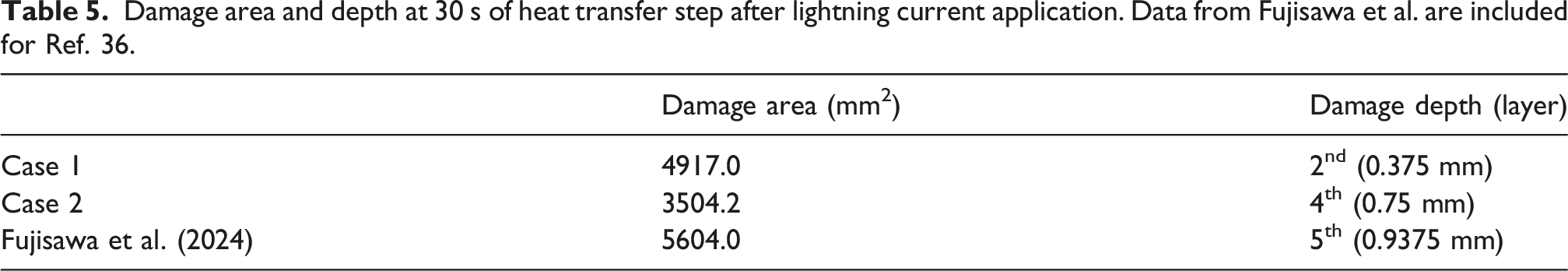
Contour plots illustrating the pyrolysis field for the first five layers of Case 1 (elliptical uniform current distribution model without detailed interlayer modeling) and Case 2 (elliptical Gaussian current distribution model without detailed interlayer modeling) are shown in Figure 12. Lightning strike damage to carbon fiber composite laminates is primarily confined to the near-surface plies, where damage in the first ply is distinctly aligned with the fiber direction. When using a pyrolysis degree of 0.1 as the damage threshold, the damage area is defined as the region where the material has undergone sufficient pyrolysis to reach or exceed this threshold. Damage area of laminate is often referred to as the damage footprint area. The damage area and depth for both models are listed in Table 5. Case 1 exhibits a damage area of 4917.0 mm2, which is close to the experimental results.
36
Case 2 shows a damage area of 3504.2 mm2, corresponding to a 28.7% decrease compared to Case 1. However, the damage depth in Case 2 is significantly greater than in Case 1, which aligns more closely with experimental results.
36
Case 1 only predicted the damage depth of two layers, while Case 2, which considers the elliptical Gaussian distribution of current, predicted the damage depth of four layers, reducing the error by 66.7%. Pyrolysis degree contours of laminate at 30 s of heat transfer step: (a) Case 1; (b) Case 2. Gray area indicates a pyrolysis degree less than 0.1. Damage area and depth at 30 s of heat transfer step after lightning current application. Data from Fujisawa et al. are included for Ref. 36.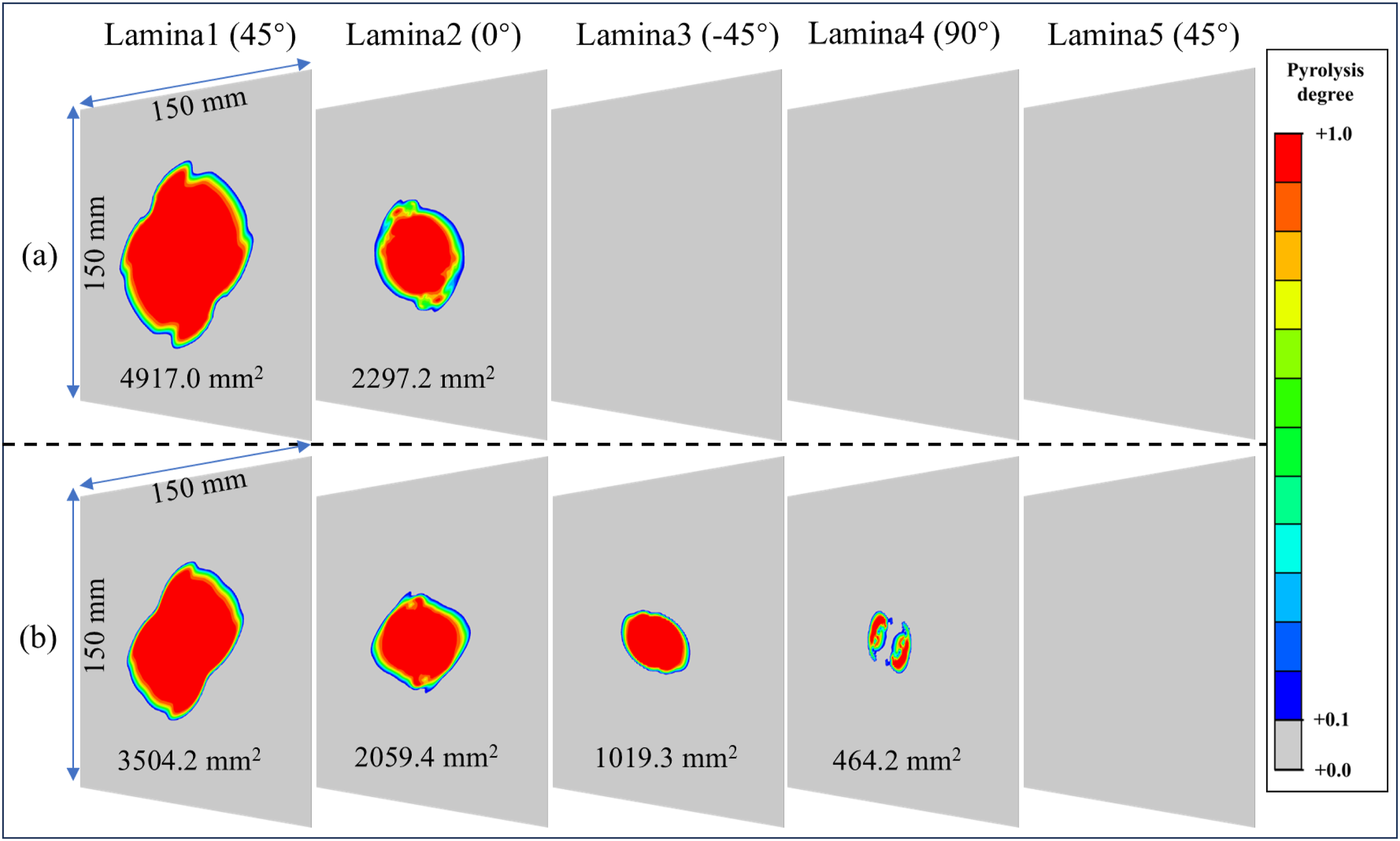
The contrasting damage characteristics can be explained by the underlying Joule heating distribution. In Case 1, the uniform current density spreads the electrical energy over a larger elliptical area, resulting in moderate but widespread surface heating. In Case 2, the Gaussian distribution concentrates the same total current (40 kA) into a smaller central region, producing substantially higher local current densities. According to Joule’s law, the heat generation rate scales with the square of the current density. Consequently, the peak temperature in Case 2 reaches 3324°C, far exceeding the 1883°C observed in Case 1, as presented in Figure 13. This intense localized heating drives deeper ablation by enabling current penetration through multiple plies, while the limited spatial extent of the high-current region restricts the overall damage area. This also explains why Fujisawa et al.
36
and Lee et al.
46
significantly underestimated through-thickness damage in laminates, whereas Dong et al.
30
successfully captured it. Both Dong et al.
30
and the present study, when employing a Gaussian-distributed current density, predicted damage areas smaller than experimental observations. Temperature contours of laminate at 30 s of heat transfer step: (a) Case 1; (b) Case 2. Gray area indicates temperature less than 300°C.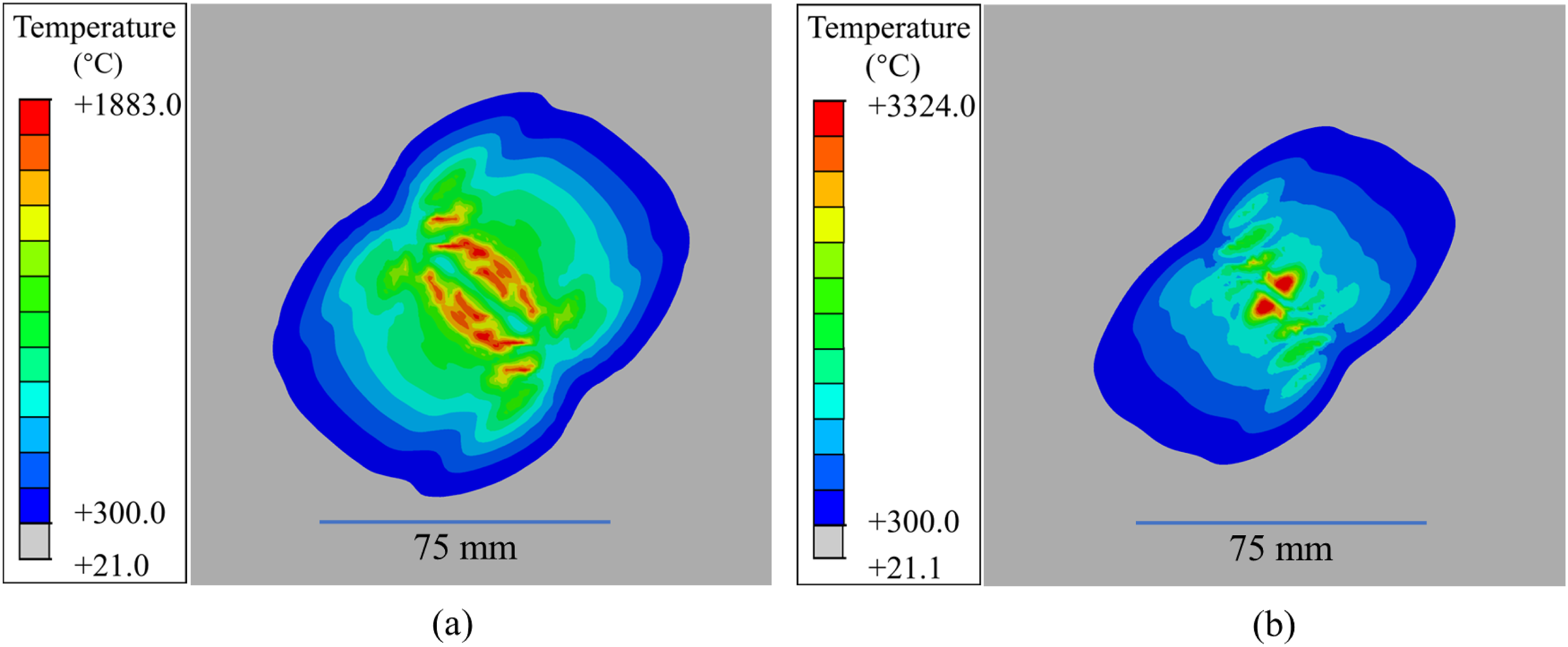
Although Case 1’s uniform current distribution better matches the experimental damage area, it fails to accurately capture damage depth, a critical factor in lightning strike damage, unlike in impact studies where damage area is typically prioritized.61–63 Lightning strike damage is often shallow and concentrated near the surface, leading to asymmetric load-bearing capacity and increasing susceptibility to buckling under compression. Dong et al. 64 and Harrell et al. 65 emphasized the importance of damage depth and volume in evaluating such damage. Li et al. 66 further showed that residual compressive strength drops sharply with delamination depth up to 1 mm, while remaining insensitive to damage area beyond 100 mm2. Thus, accurately predicting damage depth is essential for assessing post-lightning residual strength. In this study, the elliptical Gaussian current distribution (Case 2) improves depth prediction accuracy, enhancing the model’s damage tolerance relevance and overall validity by incorporating both arc channel expansion and Gaussian current distribution.
Beyond damage depth, the choice of damage threshold also influences the predicted damage area. Previous researchers27,45,46 have also employed a temperature threshold of 300°C or 500°C to assess the damage in laminates subjected to lightning strikes, as composite materials typically undergo thermal decomposition around this temperature. Using 300°C, 500°C and a pyrolysis degree of 0.1 as damage thresholds, the temperature distribution and pyrolysis degree distribution in Case 2 were plotted, as shown in Figure 14, respectively. The damage area obtained using the 300°C threshold is 5131.5 mm2, which is significantly larger than the area derived from the pyrolysis degree threshold of 0.1 (3504.2 mm2) and a threshold of 500°C (3500.6 mm2), and is closer to the experimental results.
36
While a 300°C threshold yields a smaller error in damage area prediction, the validity of using this threshold still requires verification. The pyrolysis initiation temperature of 300°C is determined under a much lower heating rate (10°C/min). As the heating rate increases, the pyrolysis initiation temperature will gradually increase. However, existing experimental and simulation results both indicate that the heating rate of carbon fiber composites during a lightning strike exceeds Damage footprint obtained from the top four layers of Case 2: (a) pyrolysis degree (Gray area indicates pyrolysis degree less than 0.1); (b) temperature (Gray area indicates temperature less than 300°C); (c) temperature (Gray area indicates temperature less than 500°C); (d) experiment result.
36
Reproduced with permission.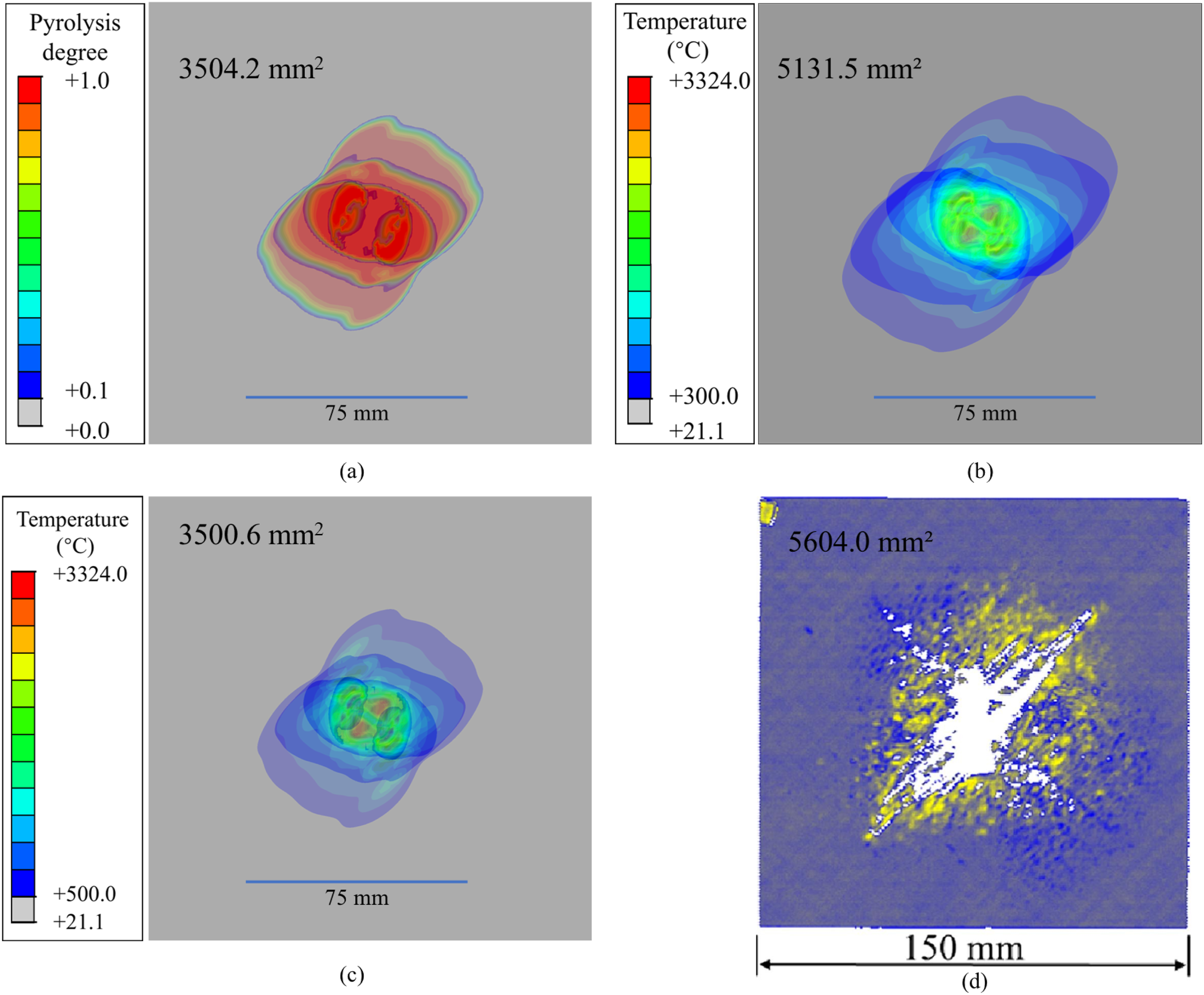
Owing to the absence of corresponding experimental studies to deepen the understanding of the detailed physical mechanisms involved, the accurate prediction of damage area has emerged as a significant bottleneck in this field. Previous studies have also incorporated additional factors such as arc heat, 30 shock-wave pressure, 69 and thermal stress30,37 to simulate lightning-induced damage in composite materials. However, since lightning current component A releases only a minimal amount of charge, the contribution of arc heat can be reasonably neglected. Furthermore, the inclusion of shock-wave pressure and thermal stress necessitates the determination of the material’s mechanical properties under ablation conditions, which poses significant experimental challenges. Existing research has demonstrated that even with these additional factors, no substantial improvements in damage area prediction have been achieved.30,37,69 Future research should focus on more in-depth investigations to elucidate the underlying mechanisms responsible for the discrepancies between current numerical models and experimental results.
By introducing the proposed elliptical Gaussian distribution model, it is possible to effectively incorporate the physical characteristics of both the elliptical expansion of the arc channel and the Gaussian distribution of current density, which have been experimentally validated, into the simulation framework. This approach addresses a significant limitation of existing models,30,41 which fail to simultaneously account for these two critical physical phenomena. As a result, the model achieves a high-fidelity translation of experimental observations into numerical simulation, significantly enhancing the accuracy of predicting key damage features.
Effect of interlayer resin enrichment
Using a pyrolysis degree of 0.1 as the damage threshold, contour plots of pyrolysis field for Case 2 (elliptical Gaussian current distribution model without detailed interlayer modeling) and Case 3 (elliptical Gaussian current distribution model with detailed interlayer modeling) are shown in Figure 15. The laminate exhibits ablation across approximately five intralayer in Case 3, with minimal damage to the sixth intralayer, aligning closely with experimental observations.
36
Considering the enrichment of interlayer resin, the damage depth error has been reduced by nearly 100% compared to Case 1. Pyrolysis degree contours of laminate at 30 s of heat transfer step: (a) Case 2; (b) Case 3. Gray area indicates a pyrolysis degree less than 0.1.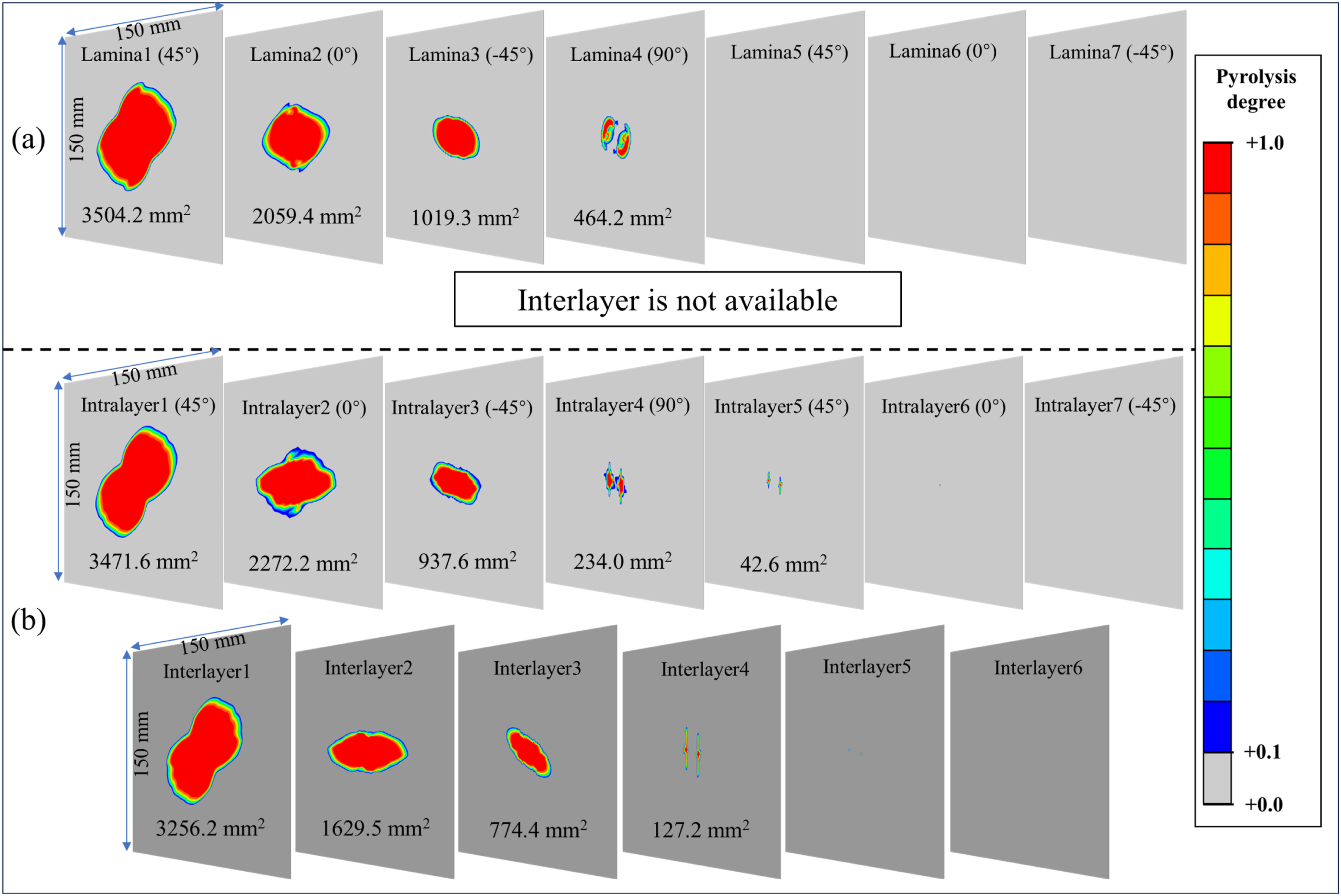
Due to the presence of interlayer, the damage response characteristics of laminate have undergone significant changes. In contrast to Case 2, Case 3 exhibits minimal damage coupling between adjacent intralayer in Figure 15. The intralayer damage in Case 3 is primarily driven by current conduction within that ply, with the damage distributed along the fiber direction of each layer. This is largely consistent with the Micro-computed Tomography (micro-CT) findings of Wang et al. 67 In contrast, the interlayer damage is mainly influenced by the damage in the preceding interlayer. Initially, owing to the high in-plane conductivity of the material, the current predominantly flows along the intralayer. Due to the shared nodes between adjacent intralayer and interlayer elements, the combined effects of the potential gradient and thermal conduction lead to dielectric breakdown or ablation in the thickness direction of the interlayer. As a result, the current gradually propagates through the thickness, reaching subsequent intralayer and inducing further ablation. Consequently, interlayer damage is significantly influenced by the intralayer. Conversely, intralayer damage is only mildly affected by the preceding interlayer. This decoupling of temperature fields between adjacent plies is a direct result of explicitly modeling the interlayer and reducing its thermal conductivity once the pyrolysis degree exceeds 0.1, which simulates delamination and hinders downward heat transfer. In most previous studies, 27 adjacent laminas share nodes without considering interlayer. Strong temperature field coupling between laminas occurs, causing damage in the previous lamina to significantly affect the next layer. The present work overcomes this limitation.
The distinct damage behaviors between Case 2 and Case 3 can be understood by examining the potential gradient distribution during current loading. Figure 16 shows the potential gradient contour plots for Case 2 and Case 3. Although both models exhibit the same breakdown depth, their breakdown morphologies differ. In Case 2 (without interlayer modeling), although the materials of each layer have directionality, the breakdown cloud map does not show this directionality clearly, but is significantly influenced by the previous layer. In Case 3 (with interlayer modeling), the interlayer breakdown morphology exhibits clear directionality aligned with the fiber angles of the adjacent plies. This indicates that the presence of resin-rich interlayers fundamentally alters the current path through the laminate thickness. Potential gradient contours of laminate at 0.0003 s of thermal-electrical step: (a) Case 2; (b) Case 3. Gray area indicates no breakdown.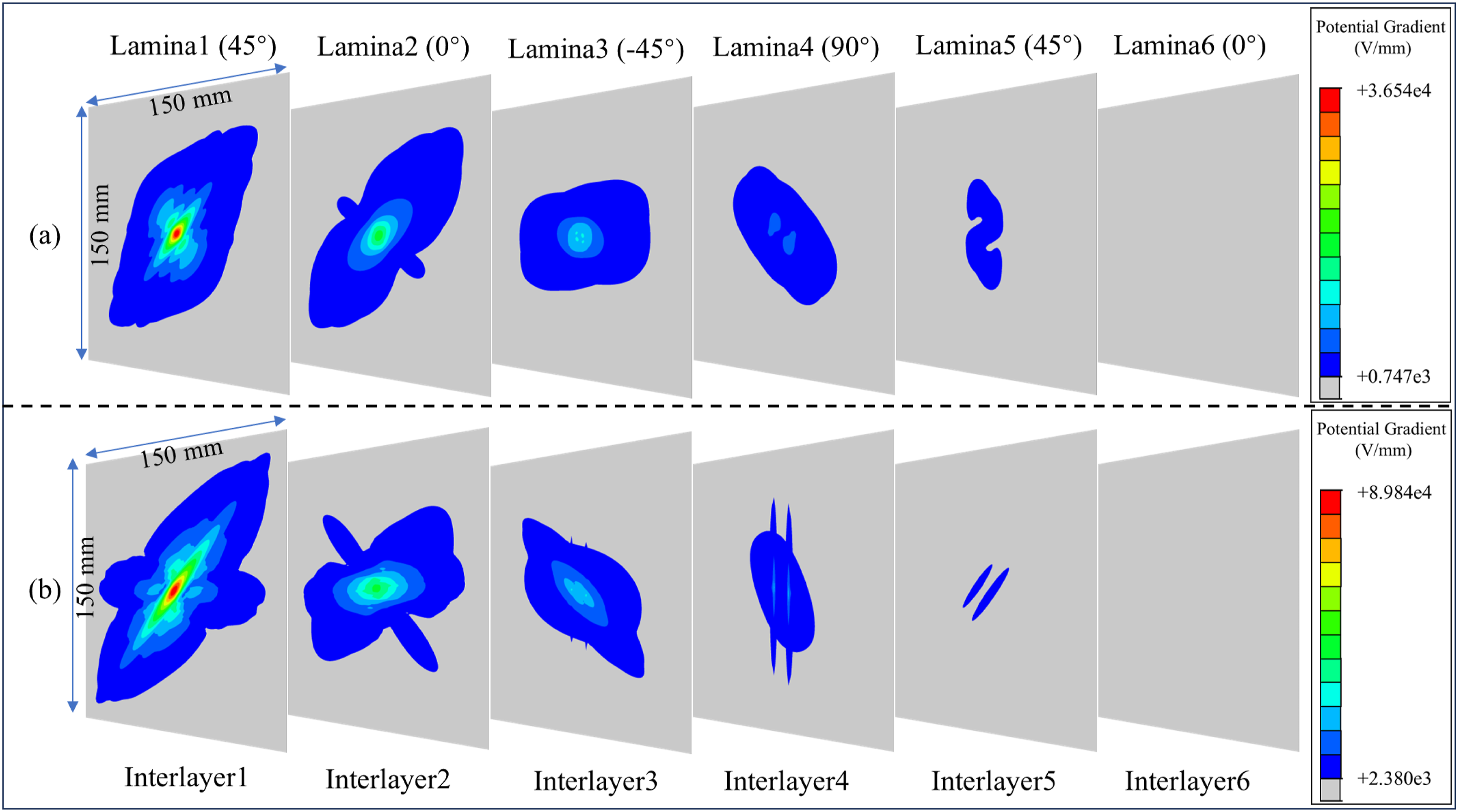
Figure 17 presents the Joule energy generated during current loading in both cases. Due to the equivalent conductivities of the two models (achieved by adjusting the intralayer in-plane conductivity as described in Section 4.4), the Joule energy produced under lightning current is nearly identical, with Case 2 generating approximately 2886.7 J and Case 3 generating about 2906.0 J, variation within Joule heat of Case 2 and Case 3 at 0.0003 s of coupled thermal-electrical step.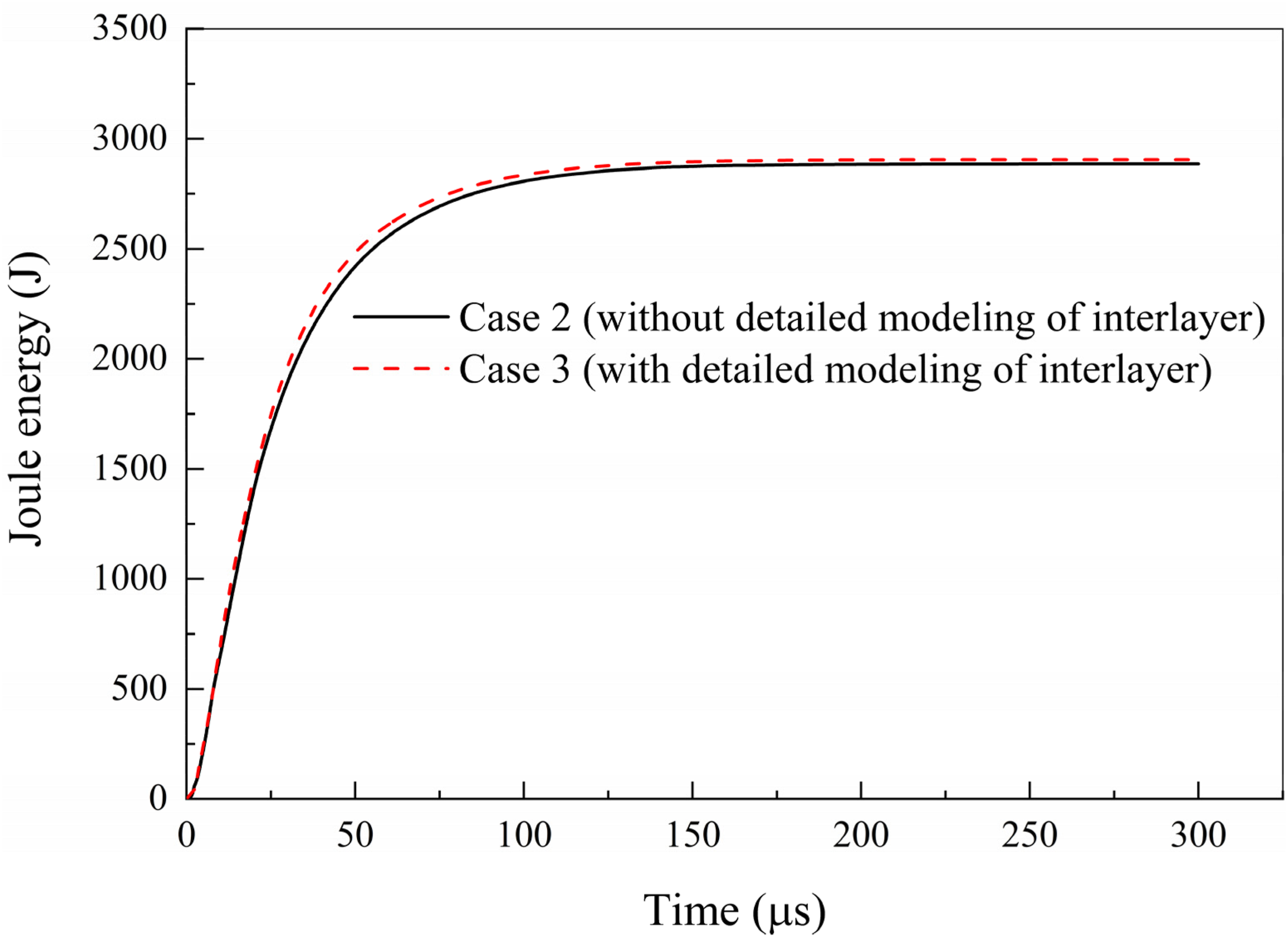
An important advantage of the proposed model is its ability to capture delamination morphology directly within the coupled thermal-electrical analysis. The delamination in composite laminates caused by lightning strikes can be effectively characterized by the pyrolysis degree of the interlayer. Figure 18 shows the damage footprint of Case 3, including both intralayer ablation (Figure 18(a)) and interlayer delamination (Figure 18(b)). The delamination area is 3486.5 mm2, slightly smaller than the intralayer ablation damage area (3691.2 mm2). Notably, the overall delamination morphology exhibits a clear directional dependence correlated with the fiber orientation of the surface layer (45°), which is consistent with the experimental results
36
(Figure 18(c)). The damage footprint: (a) damage area of intralayer; (b) delamination area of interlayer (Gray area indicates a pyrolysis degree less than 0.1); c) experiment result.
36
Reproduced with permission.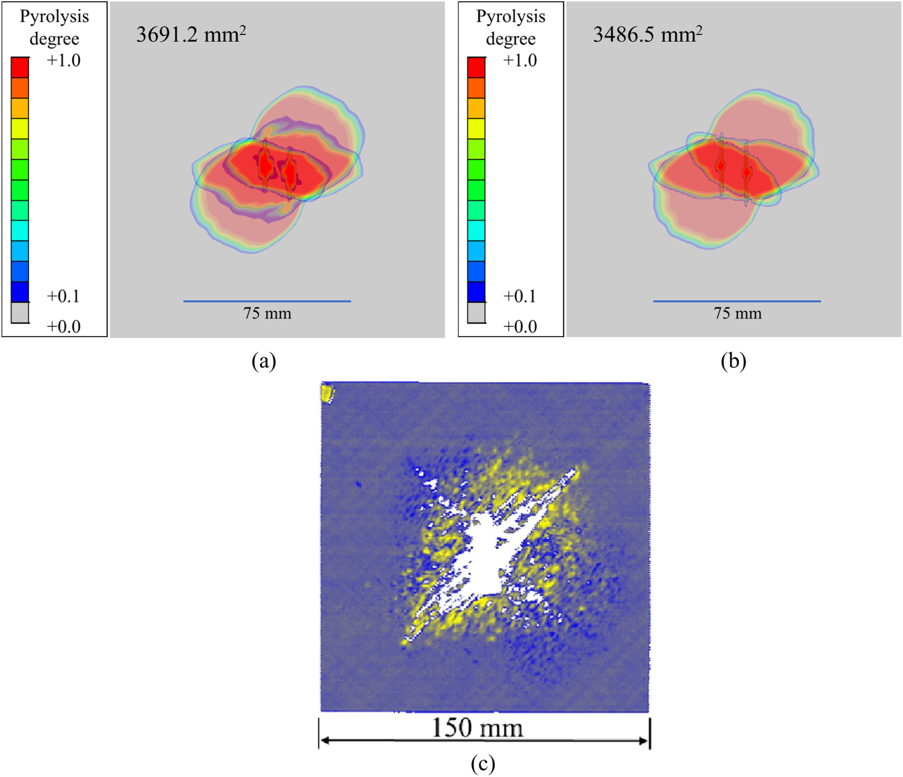
The ability to directly capture delamination morphology distinguishes the present model from previous approaches. The decomposition area of the lamina is often assumed to represent the delamination area due to the absence of detailed interlayer modeling in numerical simulations, 27 conflating intralayer ablation with interlayer delamination. In addition, as mentioned before, due to the use of shared nodes modeling, there is severe coupling between adjacent layer damages, which further distorts the delamination damage. Researchers have also proposed alternative approaches to evaluate delamination damage in laminates.37,70 Kamiyama et al. 37 conducted a thermal-stress analysis following coupled thermal-electrical and heat transfer analyses to assess delamination caused by thermal expansion. Similarly, Millen et al. 70 employed thermal-mechanical modeling following thermal-electrical damage modeling to predict delamination from combined dynamic loading and temperature. These studies37,70 did not consider interlayer resin enrichment and did not explicitly model the interlayer in the thermal-electrical coupling analysis. As a result, they were unable to simulate interlayer ablation in real time with high resolution, and thus could not effectively capture the delamination behavior of the laminate. By contrast, the present model captures delamination directly within the coupled thermal-electrical analysis by using interlayer pyrolysis degree as a delamination indicator. This approach eliminates the need for separate mechanical simulations and provides a more physically consistent representation of the delamination process. Naturally, this model can be further extended to include mechanical loads and thermal stresses for more precise simulation of lightning strike damage in carbon fiber composites. It is worth noting that this research was conducted based on conventional finite element methods, which still have limitations in terms of damage crack propagation and computational efficiency. In the future, this method could be integrated with emerging meshless algorithms 71 and machine learning techniques72–74 to enable more accurate and efficient simulation of lightning strike damage to carbon fiber composite laminates.
This study provides a novel research perspective for investigating lightning strike damage in composite materials. Fujisawa et al. 36 confirmed the influence of dielectric breakdown effects on the electrical conductivity of composite laminates during lightning strikes, thereby challenging the previously assumed virtual dependencies of through-thickness conductivity on temperature or pyrolysis degree in existing studies. This study further attributes the overall dielectric breakdown of laminated panels to interlayer dielectric breakdown. By applying relevant electrical principles, the interlayer dielectric breakdown strength was determined. Additionally, a refined numerical model incorporating the effects of interlayer resin enrichment was developed to investigate the intralayer damage and interlayer delamination response of laminated panels under lightning strike. This study not only promotes the modeling of direct lightning strike damage in composite materials, but also has the potential to provide interpretable physical inputs for modeling research on residual strength after lightning strike and lightning strike protection in composite materials in the future.
Summary of key findings
In summary, the main findings of this study are as follows, as shown in Figure 19: (1) Considering both the elliptical Gaussian current distribution and interlayer resin enrichment significantly reduces the prediction error of damage depth; (2) Considering the elliptical Gaussian current distribution leads to a marked increase in the central temperature of the model; (3) Explicit interlayer modeling that accounts for interlayer resin richness enables the simultaneous capture of intralayer ablation and interlayer delamination damage within a thermal-electrical coupling analysis; (4) Explicit interlayer modeling considering interlayer resin enrichment does not alter the total Joule energy of the model. Key findings of this research: (a) damage depth of the three models; (b) peak temperature of uniform and gauss current distribution; (c) intralayer ablation and interlayer delamination; (d) Joule energy of Gauss current distribution with and without interlayer resin enrichment.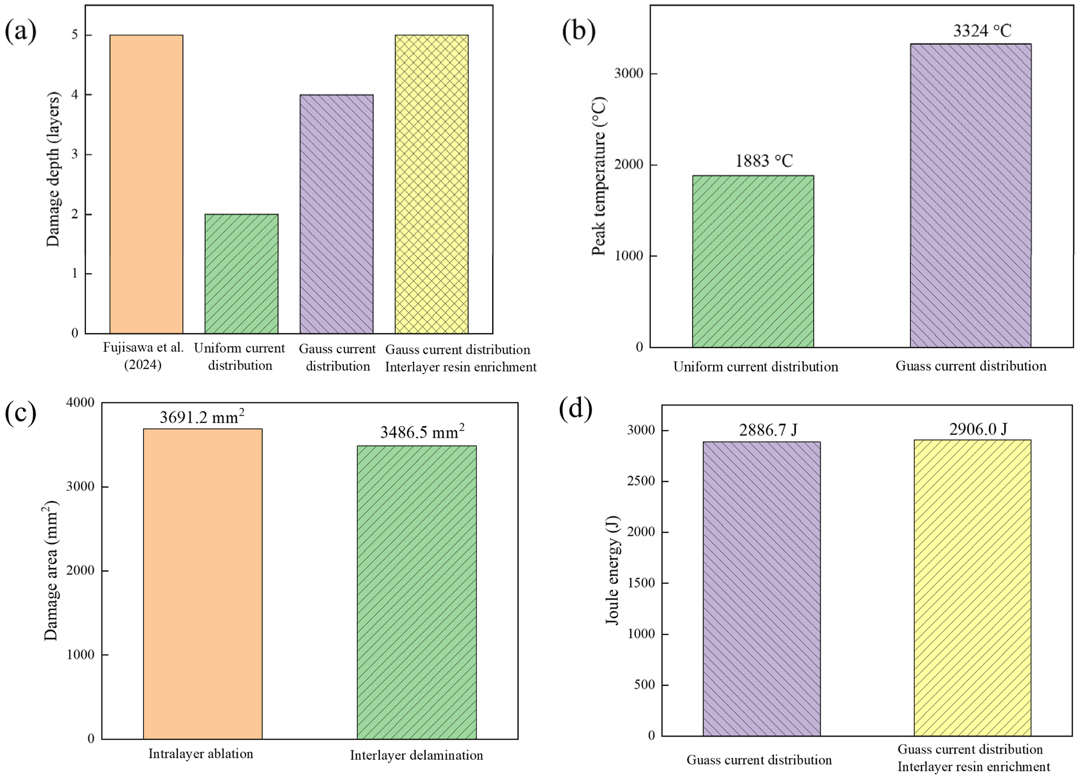
Conclusion
This study developed a novel numerical framework for predicting lightning strike damage in composite laminates by integrating two previously overlooked mechanisms: elliptical Gaussian current distribution and interlayer resin enrichment with dielectric breakdown. The proposed model was validated against experimental results from Fujisawa et al.
36
Main conclusions have been drawn as follows: (1) Considering the elliptical Gaussian current distribution and interlayer resin enrichment effectively improves the accuracy of damage depth prediction. Case 2 (Gaussian current distribution) reduced depth error by 66.7% versus Case 1 (uniform current distribution); Case 3 (elliptical Gaussian current distribution, interlayer resin enrichment) achieved nearly 100% error reduction, matching experimental depth (5 plies, 0.9375 mm). (2) Considering the elliptical Gaussian distribution of current significantly alters the temperature distribution. The peak temperature of Case 2 reached 3324°C compared to 1883°C for Case 1, explaining deeper ablation via Joule heating concentration. (3) Explicit interlayer modeling considering interlayer resin enrichment efficiently captures interlayer delamination behavior. Case 3 captured both intralayer ablation (3691.2 mm2) and interlayer delamination failure (3486.5 mm2) in composite laminates via coupled thermal-electrical analysis, eliminating the need for separate mechanical simulations. (4) Explicit modeling of interlayer resin enrichment alters the energy distribution without altering the total energy. Joule energy variation between Case 2 and Case 3 was within 1%, confirming that the damage morphology was altered due to energy redistribution rather than additional input.
A limitation of this study is that validation is performed against a single experimental dataset 36 due to the lack of publicly available data containing all necessary inputs (arc expansion, material properties, and detailed damage characterization). Future work should include systematic experimental campaigns with varying parameters (stacking sequences, laminate thicknesses, and current waveforms) to provide a more comprehensive validation of the proposed model. In addition, this study primarily employs a thermal-electrical coupling analysis method to investigate lightning strike ablation damage. In future work, mechanical loading effects and the degradation of material properties due to high temperatures can be further incorporated to enable more effective simulation of lightning strike damage to carbon fiber composites.
This research offers deeper insights into the failure mechanisms of composite laminates during lightning strikes, and has broad application prospects in the evaluation of residual strength performance after failure and the effectiveness of failure prevention design (lightning strike protection).
Supplemental material
Supplemental material - Incorporating elliptical Gaussian current and interlayer resin enrichment for lightning damage prediction in composite laminates
Supplemental material for Incorporating elliptical Gaussian current and interlayer resin enrichment for lightning damage prediction in composite laminates by Pei Xiao, Bin Yang, Jiang Xie, and Zhenyu Feng in Journal of Reinforced Plastics and Composites
Footnotes
Acknowledgment
The authors would like to express their appreciation for the financial support provided by the National Key R&D Program of China [2022YFB4301000].
CRediT author statement
Funding
The authors disclosed receipt of the following financial support for the research, authorship, and/or publication of this article: This work was supported by the National Key Research and Development Program of China [2022YFB4301000].
Declaration of conflicting interests
The authors declared no potential conflicts of interest with respect to the research, authorship, and/or publication of this article.
Data Availability Statement
Supplemental material
Supplemental material for this article is available online.
Appendix
References
Supplementary Material
Please find the following supplemental material available below.
For Open Access articles published under a Creative Commons License, all supplemental material carries the same license as the article it is associated with.
For non-Open Access articles published, all supplemental material carries a non-exclusive license, and permission requests for re-use of supplemental material or any part of supplemental material shall be sent directly to the copyright owner as specified in the copyright notice associated with the article.