
Abstract
Glass fibre reinforced polymer (GFRP) composites incorporating ceramic fillers have gained increasing interest for applications requiring enhanced mechanical strength and wear resistance. In this work, the mechanical and tribological responses of GFRP composites as a function of boron carbide (B4C) particle size are systematically investigated at low filler fractions of 1 and 2 wt%. GFRP laminates were fabricated using the hand lay-up method, followed by cut-through abrasive water jet cutting in accordance with ASTM standards. Tensile tests were performed on specimens with and without a central 10 mm hole, Izod impact tests were performed to assess the impact performance, and dry sliding wear behaviour was evaluated under controlled conditions. The results indicated that the composites with 1 wt% B4C and fine particle size have higher tensile and impact strength than unfilled GFRP due to the effective load transfer and uniform filler dispersion. Increasing the filler content to 2 wt% causes particle agglomeration and formation of micro voids, which leads to a reduction in ductility and promotes premature failure. Tribological results show that the finer the B4C particle size, the more it improves the wear rate and increases the surface stability, while the coarse particles will cause more abrasive damage. Scanning electron microscopy shows the particle-size dependency, dispersion behaviour, and damage mechanisms of mechanical and wear response. These results give a mechanistic understanding of particle size-controlled reinforcement effectiveness and wear characteristics of B4C-filled GFRP composites.
Keywords
Introduction
The glass fibre reinforced polymer (GFRP) composites have found widespread applications in aerospace, automobile, marine, and structural reinforcements due to their high strength-to-weight ratio, corrosion resistance, and design flexibility.1,2,3 However, their relatively low wear resistance and susceptibility to surface damage under sliding contact limit their performance in applications involving frictional loading.4,5,6 To overcome these limitations, the incorporation of ceramic fillers into polymer matrix composites has emerged as an effective strategy to enhance mechanical integrity and tribological stability.7,8,9 Adding fillers made from ceramic, metallic, or natural sources into the matrix improves mechanical and thermal properties, wear resistance, and machinability.10,11 Incorporation of fillers leads to appreciable alterations in composite microstructure, interfacial bonding characteristics, and mechanical properties under mechanical loading exerted and machining operations.12,13 Selecting the right filler materials is crucial in defining the mechanical properties of GFRP composites.14,15 Single and hybrid nanoparticles added to GFRP composites enhance mechanical performance and impact resistance and energy absorption by increasing filler dispersion and fibre-matrix interfacial bonding. When compared to single filler composites, hybrid nanoparticle systems have increased stiffness, strength, and energy absorption.16,17
The distribution of the fillers in the composite largely influences the performance of the material properties. Uniform distribution has the potential to make the composite stronger and harder to wear.18,19 The filler content is critical in defining composite properties, as any increase in filler content can improve the properties of the composites in terms of many factors, like stiffness or thermal resistance, but also it could deteriorate other properties like tensile strength or ductility, because of filling, which can lead to agglomeration or poor distribution of the filler. 20 Wollastonite and barium sulphate have superior applications due to their high density, which enhances rigidity and dimensional stability in the composite. The glass particles improve thermal and electric insulating capability, which is applicable in the aerospace and electronics industries. 11 The addition of nanofillers, such as carbon nanotubes and nano-silica, enhances the flexural behaviour of glass/epoxy composites by increasing the interfacial bonding and inhibiting the propagation of delamination. Advanced damage monitoring techniques show that nanomodified composites have a delayed damage onset and better load-bearing capability than unmodified laminates. 21 Addition of 1–2% multi-walled carbon nanotubes (MWCNTs) remarkably increased the tensile strength of the composite from around 114.51 MPa to 155.53 MPa, showing the efficiency of nano-sized replacement fillers. However, the decrease in strain at failure slightly indicates compromise with ductility at higher MWCNT content. 22 The incorporation of hybrid fillers (ilmenite and silicon dioxide in the mixture of 5:5 wt%) in GFRP composites leads to a significant enhancement in their mechanical properties. This consists of enhanced tensile strength (30.54), tensile modulus (12.2), flexural strength (32.22), and flexural modulus (28.98) in comparison with neat samples. 23 In the same manner, addition of graphene oxide (GO) and silicon carbide (SiC) fillers results in improved tensile and flexural moduli, and the values of 8.03 GPa and 13.59 GPa are realised at 0.5 wt% of graphene oxide concentration. 24 Although adding 10% of boric acid (BA) to GFRP composites provided enhancement of the mechanical strength, it was mainly due to the amorphous nature of BA that enhanced interfacial bonding and better stress transfer in the composite matrix. 25
Among the many ceramic fillers, boron carbide (B4C) offers advantages over commonly used fillers such as Al2O3, SiC, and TiO2, including extremely high hardness, low density, high elastic modulus, and good chemical and thermal stability. These attributes allow B4C to increase wear resistance and load-bearing capability without having to significantly increase the composite weight. Furthermore, in comparison with solid lubricant fillers, graphite, etc., B4C has better reinforcement efficiency, so B4C is more suitable for applications requiring a balance between mechanical strength, impact resistance, and tribological function.26,27 In PTFE-based composites, B4C increases tensile strength, Young’s modulus, and wear resistance and decreases the friction coefficient, rendering the material more durable and more suitable for high-performance, thermally and mechanically challenging applications.28,29 The addition of 2 wt% B4C has been shown to have both improved tensile strength and flexural properties, and the least back face signature and the highest specific energy absorption during the high velocity ballistics test, indicating superior impact resistance in GFRP composites. It also helps in improving interphase adsorption between the glass fibres and the epoxy matrix to minimise two popular failure modes in unfilled composites (matrix cracking and fibre breakage). 30 The incorporation of synergistic fillers (boron carbide and graphene) significantly improves the mechanical properties of glass fibre-reinforced epoxy composites. Particularly, the hardness, tensile, and flexural strengths were enhanced by 38%, 25%, and 19%, respectively, at 0.3 wt% B4C. 31 The presence of B4C forms a hard surface, which helps in the reduction of wear rate and the longevity of the materials under frictional influences. The coefficient of friction was reduced when the content of B4C increased, and a minimum value was observed at 10 vol% B4C content. The values indicated smoother surfaces to slide off and a low amount of energy wasted during motion. 32 The introduction of B4C may result in a more uniform distribution of thermal heat, subsequently reducing thermal resistance and improving thermal pathways, which promotes the high efficiency of heat transfer through the composite material.33,34
Although extensive research has been conducted on ceramic-filled glass fibre reinforced polymer (GFRP) composites, particularly B4C-filled polymer and GFRP composites, most studies have focused on the effects of filler loading or higher filler contents. In contrast, limited attention has been given to the influence of B4C particle size, especially at low filler contents (1–2 wt.%). Furthermore, mechanical and tribological responses are often studied independently, without establishing clear correlations with particle-size-controlled dispersion, interfacial integrity, and damage mechanisms. The influence of B4C particle size on wear stability and damage tolerance under stress-concentration conditions, such as in holed specimens relevant to practical machining and assembly, also needs further investigation. In this regard, the present investigation fulfils a particle-size-controlled characterisation of B4C reinforced GFRP composites at 1 and 2 wt% fillers by combining mechanical testing, tribological investigation, and the use of a scanning electron microscope (SEM) to evaluate their microstructure in order to determine the correlations between the composite structure, properties, and wear characteristics. The work focuses on understanding the importance of B4C particle size for load transfer efficiency, wear behaviour, and damage tolerance, and on the critical transition from efficient reinforcement to agglomeration-induced performance degradation. This is an integrated approach that provides mechanistic insight into particle-size-controlled reinforcement efficiency in GFRP composites and addresses a critical gap in the current literature.
Experimental methodology
Materials
The raw materials used for the fabrication of the composite specimens are shown in Figure 1. Unidirectional glass fibre (300 GSM) was used as reinforcement because of its high tensile strength, dimensional stability, and resistance to corrosion.
35
The epoxy resin (LY556) and hardener (HY951) were used as matrix and mixed in a 10:1 weight ratio. The epoxy has been chosen as it has good adhesion and low shrinkage, and also its mechanical properties are stable.
36
To improve the mechanical and wear resistance properties of the composite, boron carbide (B4C) powder was added as a filler, at a concentration of 1 wt% and 2 wt% of the overall weight of the composite. The B4C was selected because it has high hardness, low density, and exhibits excellent tribological performance.37,38,39 The composites were prepared with three different sizes of boron carbide: B1 (1–10 µm), B2 (20–30 µm), and B3 (40–50 µm) to investigate the effect of particle size on the mechanical and tribological properties of the composites. Raw materials used for composite fabrication: (a) unidirectional glass fibre reinforcement, (b) boron carbide (B4C) powder used as ceramic filler, and (c) epoxy resin (LY556) employed as the matrix material.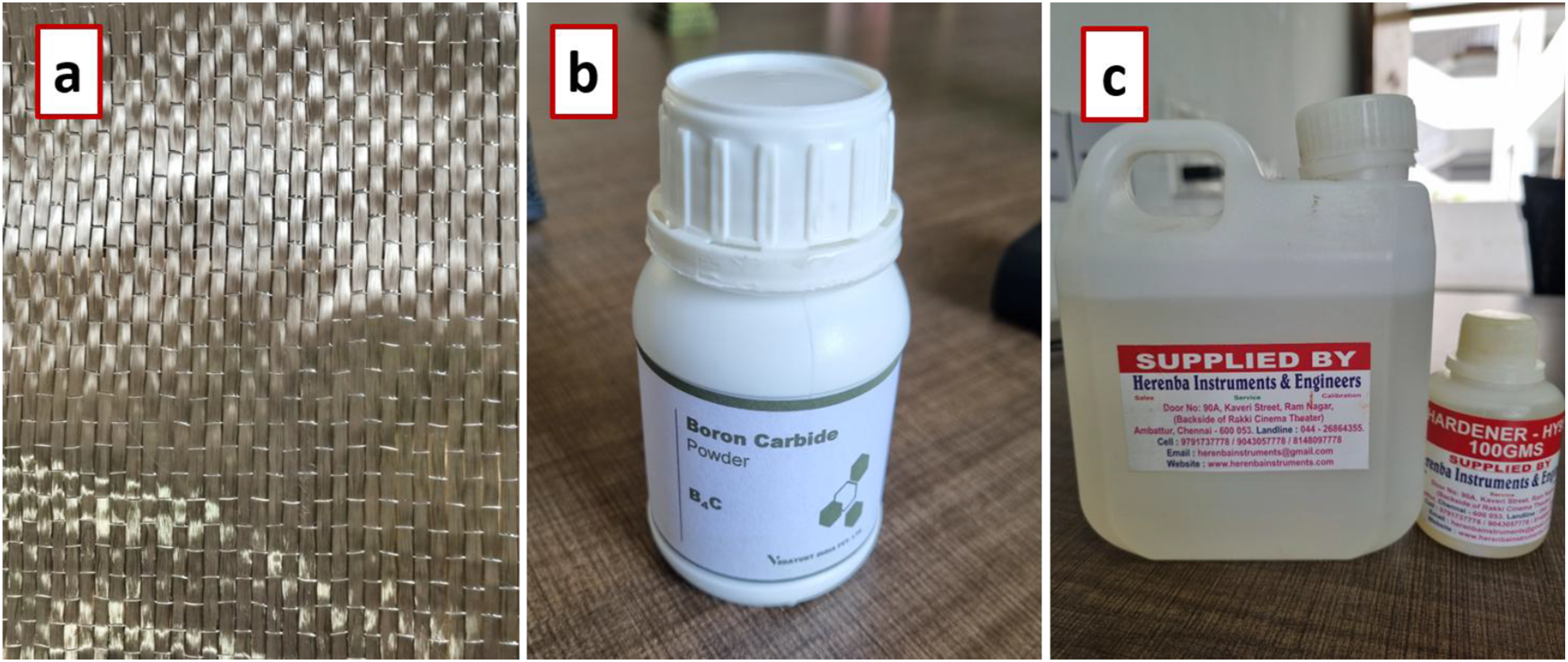
Fabrication process
The composite laminates were fabricated via a hand lay-up process (Figure 2), an easy and cost-effective way of performing the same in small-scale production, prototyping, or research. It is easy to customise the shapes and sizes, and hence it is suitable when dealing with detailed designs. It does not need much equipment, and it is flexible, as changes can be quickly made without having complex machines in use.40,41 The composition of the fabricated GFRP composite, including the weight percentage of each constituent, is shown in Table 1. Composite fabrication procedure: (a) schematic illustration of filler mixing with epoxy resin, (b) mechanical stirring of the resin-filler mixture, and (c) hand lay-up of the GFRP composite. Composition of GFRP composite.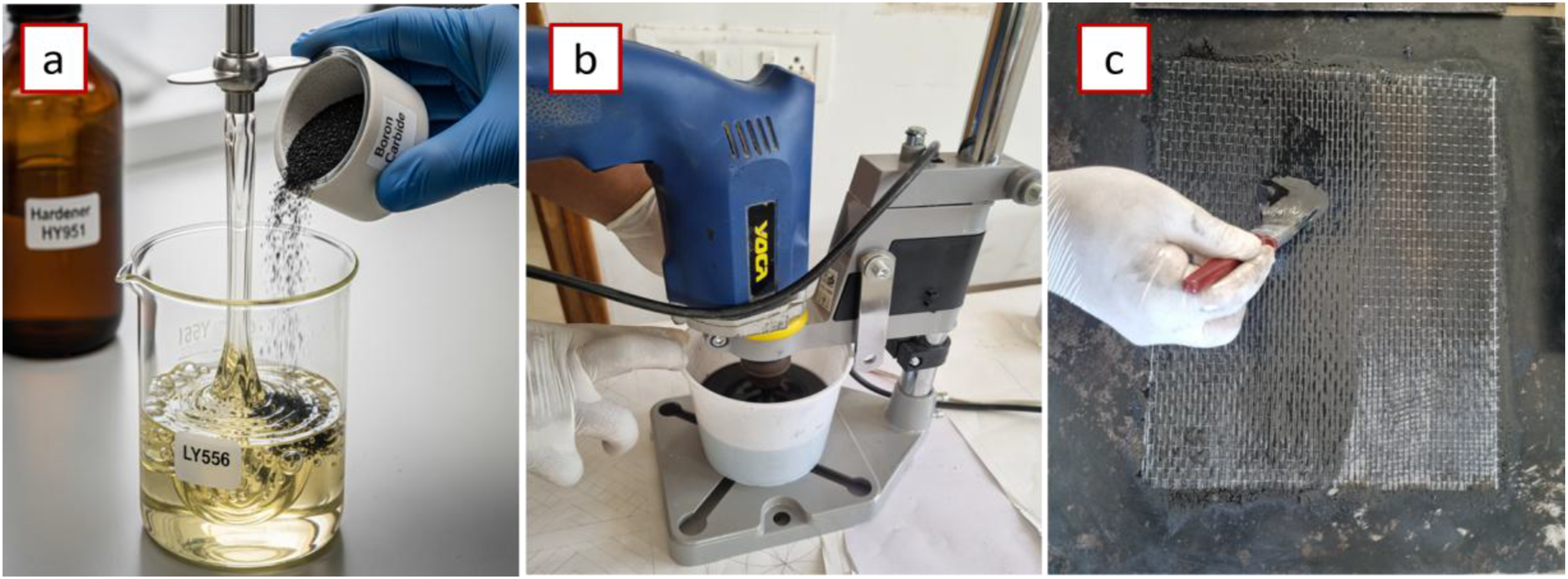
The B4C filler content of 1 wt% and 2 wt% was chosen on the basis of previous research on ceramic-filled polymer composites, which shows that low filler contents are useful to enhance mechanical and tribological properties, and high filler contents tend to cause agglomeration of particles, ineffective dispersion, and degradation of properties. The range selected thus was to obtain the shift between good reinforcement (1 wt%) to agglomeration-controlled behaviour (2 wt%), in order to obtain a systematic assessment of particle-size effects with low filler content conditions.
To assure uniform dispersion of B4C particles in a matrix of epoxy resin, a controlled multi-step mixing procedure was adopted. The epoxy resin (LY556) and the hardener were first thoroughly mixed, and then the necessary amount of B4C powder was added slowly under constant mechanical stirring to avoid the sudden agglomeration of the particles and promote relatively uniform particle dispersion within the matrix and minimise particle agglomeration. This was followed by mechanical stirring (Figure 2(b)) at constant speed over a prolonged period of time, which permitted good wetting of the B4C particles in a resin. Care was taken not to allow excessive shear, which might cause air entrapment. Periodic scraping of the resin-filler mixture off the container walls was also done to further encourage uniform dispersion. The resulting mixture was slowly mixed to achieve a uniform, bubble-free consistency before the hand lay-up process was undertaken. This procedure was always followed for all filler contents and particle size to minimise agglomeration and ensure good dispersion quality. The particle distribution evaluation of the present work was largely conducted on SEM observations obtained from multiple representative regions of the composites sample. These observations indicated that dispersion was fairly uniform for lower filler content and that there was some agglomeration at higher filler content; however, no quantitative image-processing analysis or particle distribution index was conducted. These quantitative methods could offer a more rigorous evaluation of dispersion quality and are recommended for future research.
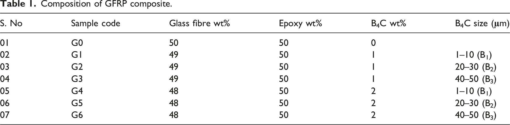
A clean metal plate was used as the mould base, and a mould release wax was applied to the plate to make it easier to remove after the curing process. The glass fibre sheets were cut to the recommended size and stacked accordingly at a 0-degree angle. The epoxy and B4C mixture were manually applied to each layer of the fibre using a brush and roller to eliminate air bubbles accurately. A metal sheet is placed over it and subjected to a uniform load. The laminates were subsequently cured under ambient conditions for 24 h. After curing, the composite laminates were taken out of the mould and cut into the desired shape by using abrasive water jet machining (AWJM) as shown in Figure 3. The cutting was carried out at a speed of 200 mm/min with 80 mesh garnet as the abrasive material. This technique provided precise, clean cuts without causing thermal damage or delamination.42,43,44 The specimens were subjected to both mechanical and tribological testing in accordance with the relevant ASTM standards. Specimen preparation and machining sequence: (a) fabricated GFRP composite laminates after curing, (b) abrasive water jet machining (AWJM) used for specimen cutting, and (c) final test specimens prepared according to relevant ASTM standards.
Tensile testing
Tensile testing (Figure 4) of B4C-filled glass fibre reinforced polymer (GFRP) was carried out according to standard ASTM D3039 to assess its tensile values. Two specimen configurations, non-holed specimens, and holed specimens (10 mm diameter, centrally located hole) were fabricated to investigate how the stress concentration affects tensile performance. The testing was carried out with the help of CIPET Raipur on a 100 kN load range servo electro-mechanical universal testing machine (UTM) at a constant crosshead speed of 1 mm/min under a static tensile load environment. Tensile testing of GFRP composites: (a) universal testing machine (UTM) setup, (b) close-up view of the gripped specimen during testing, and (c) fractured specimen after tensile testing.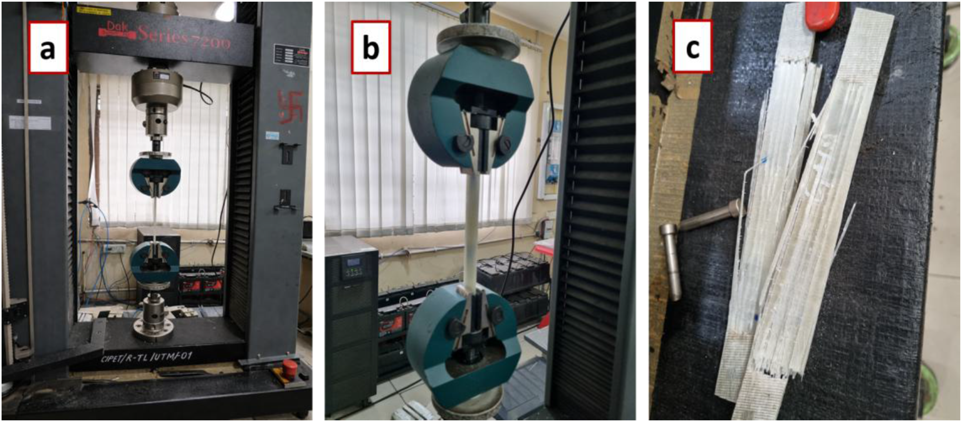
Specimens were securely fastened to ensure correct alignment and prevent slippage, thereby avoiding early failure. The key parameters, ultimate tensile strength (UTS), Young modulus (E), stress concentration factor of holed specimens (Ktexp), as well as strain at failure (ℇfailure %), were calculated by the formulas below using equations (1)–(4), where Fmax is the maximum load at failure (N), A is the cross-section area of the specimen (mm2), E is the tensile modulus (GPa or MPa), F1 and F2 are two previous points in the elastic zone (N), δ1 and δ2 are corresponding elongations (mm), L0, and ΔL is the gauge length (mm) and elongation at fracture (mm), respectively, σholed is the ultimate tensile stress of the holed specimen (MPa), and σunholed is the ultimate tensile stress of the non-holed specimen (MPa).
Ultimate tensile strength (UTS):
Tensile modulus (Young’s modulus):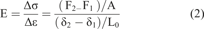
Strain at failure (% elongation):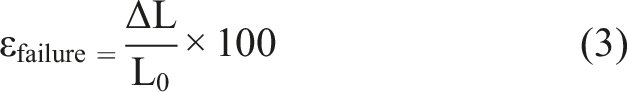
Stress concentration factor (for holed specimens):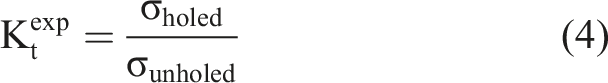
A comparison study between holed and non-holed specimens was also done to know how geometric discontinuities influence the load-bearing capacity, stress distribution of the composite materials and fractures.
Izod impact testing
The composite specimens were tested in Izod impact testing (Figure 5) with notched samples according to the ASTM D256. Rectangular specimens were prepared with a conventional V-notch to achieve crack initiation at impact loading. The samples were placed upright in the Izod impact test equipment, whereby a pendulum hammer was used to impose an impulsive force to fracture the sample at the notch point. (a) Izod impact testing setup and (b) fractured GFRP specimen after impact loading.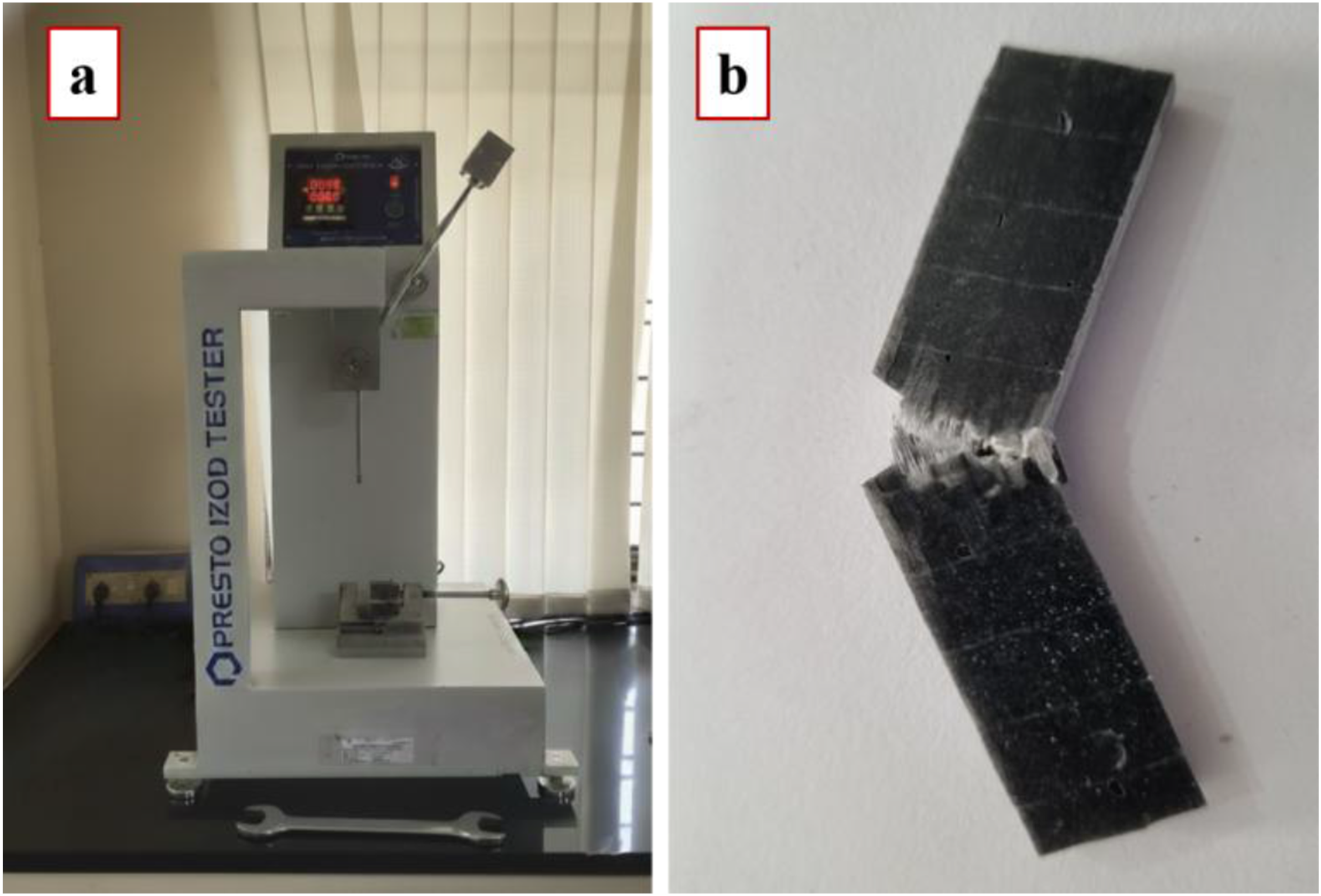
The energy absorbed (E) during fracture was recorded in Joules, and the Izod Impact Strength (Is) was calculated using the formula:
Tribological testing
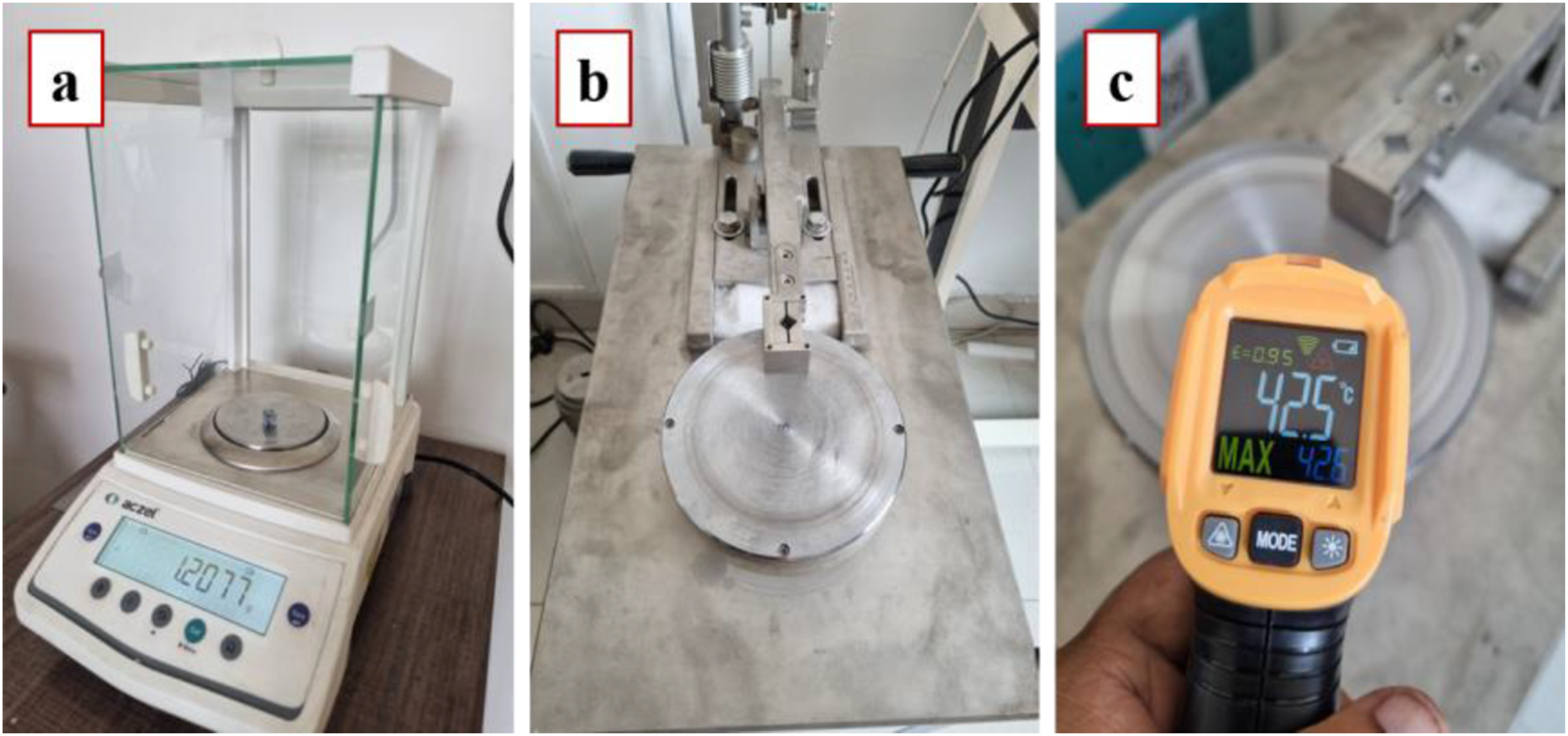
Wear tests were conducted to determine the tribological characteristics of the materials based on the ASTM G99 standard using the Pin on Disk Apparatus with a disk roughness of 7.5–10 μm, as shown in Figure 6. Composite pins that are square, 10 mm across, were made and slipped under dry sliding conditions and on a rotating EN31 steel disk. A pin-on-disk tribometer was used to perform the tests, during which the following parameters were controlled: applied loads of 140 N, 160 N, and 180 N, at different sliding velocities of 4 m/s, 5 m/s, and 6 m/s with a constant sliding distance of 2000 m, as per the experimental plan. The mass loss of the pin specimens before and after the test was determined using a high-precision digital balance. The wear-rate (W) was then determined by the formula. Experimental setup and testing: (a) specimen weighing, (b) pin-on-disk wear testing machine, and (c) temperature measurement during testing.
The disk temperature and coefficient of friction (μ) were measured throughout the test. The worn surfaces were analysed after the test to determine the wear mechanisms: matrix degradation, fibre pull-out, abrasive wear, and ploughing effects of B4C filler particles. The wear resistance and frictional behaviour of the GFRP composites with filler addition were assessed using the test results.
Results and discussion
Morphological characterisation and elemental mapping
The surface morphology and size of boron carbide particles were examined by scanning electron microscope (SEM). Figures 7 and 8 present SEM images and successive EDS elemental maps of the boron carbide (B4C) powders of various particle sizes: (a) 1–10 μm, (b) 20–30 μm, and (c) 40–50 μm. SEM micrographs of boron carbide (B4C) powder with different particle sizes: (a) 1–10 μm, (b) 20–30 μm, and (c) 40–50 μm. EDS mapping of boron carbide powder with different particle sizes: (a) 1–10 μm, (b) 20–30 μm, and (c) 40–50 μm.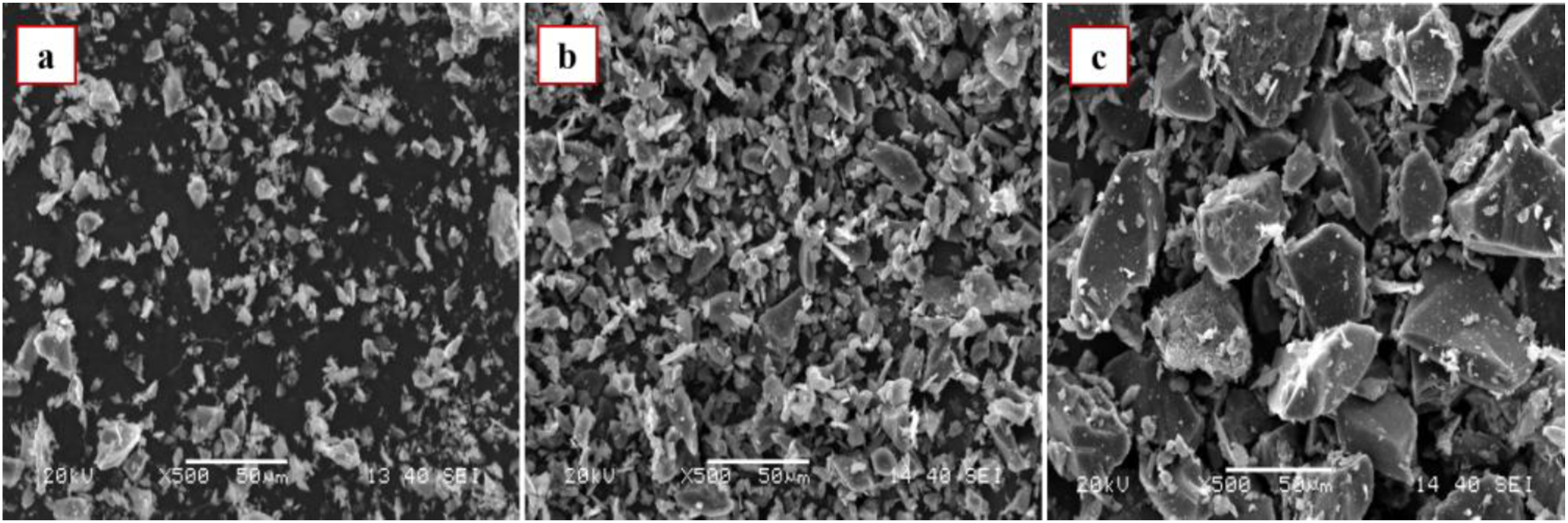

The EDS mapping confirms the distribution of boron (red) and carbon (green) throughout the samples. Although the size of the particles varies, no significant elemental segregation appears to happen, which establishes the compositional stability of the boron carbide powders.
Tensile testing
The tensile stress-strain response of glass fibre/epoxy composites with different sizes and weight fractions of B4C particles is shown in Figure 9. The neat composite (G0) showed the standard non-linear stress-strain curve of fibre-reinforced epoxy with an ultimate tensile strength (UTS) of 439 MPa at around 6.3% strain. The addition of 1 wt% B4C was found to improve tensile strength considerably, and the 1–10 μm size composite (G1) showed the highest UTS value of 478 MPa, which may be associated with improved stress distribution and enhanced interfacial interaction between the matrix and reinforcing constituents. Tensile stress-strain behaviour of GFRP composites reinforced with 1 wt% and 2 wt% B4C of varying particle sizes.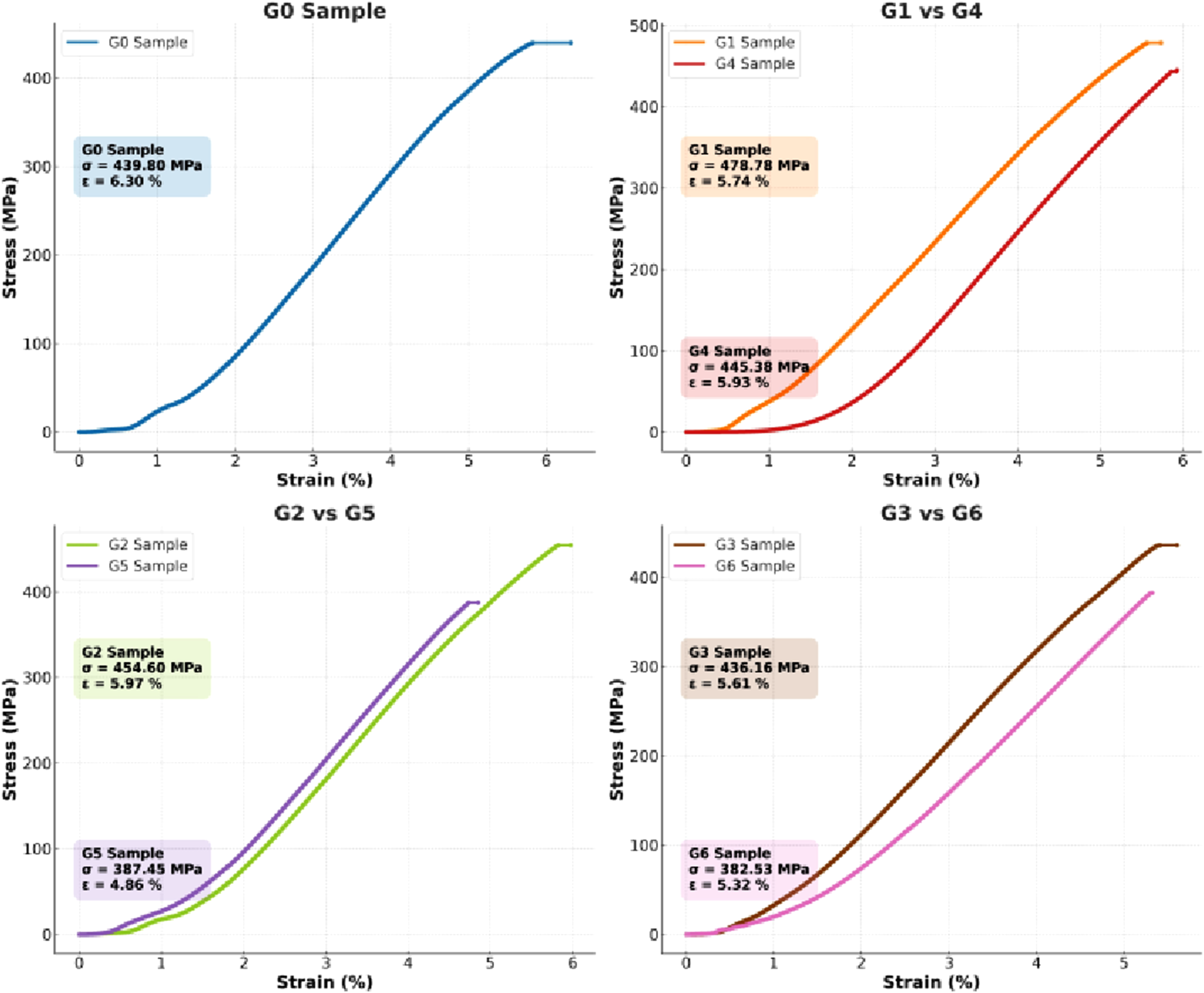
The 20–30 μm B4C composite (G2) exhibited moderate enhancement at 454 MPa, whereas the 40–50 μm specimen (G3) exhibited the lowest strength of 436 MPa with poor bonding and localised stress concentration. The enhancement of tensile strength for composites with a fine particle size of 1 wt% B4C was attributed to the effective stress transfer between matrix and fibres by the uniform dispersion of the particles and the increase of interfacial integrity.
In contrast, increasing the filler content to 2 wt% promotes particle agglomeration, which, together with possible impairment of fibre wettability and reduction in matrix continuity, may generate localised stress concentration sites that initiate premature failure and reduce tensile performance. The fine particle composite (G4) maintained the UTS value at 445 MPa, while G5 and G6 reduced to 387 MPa and 382 MPa, respectively. Towards the beginning, the stress-strain curves indicated a non-linear region attributed to deformation of the matrix and slight debonding of the filler, and the linear increase, which reflected the effective load transfer between fibre, matrix and filler. Composites with B4C loading of 1 wt% exhibited a higher slope and strength, while the 2 wt% samples exhibited a lower slope and brittle failure. Overall, the results validate that finer B4C particles at an optimum 1 wt% loading improve interfacial bonding, tensile strength, and energy absorption capability of GFRP composites due to a uniform stress distribution and crack propagation retarding.
It is also noted that composites containing 1 wt% filler were, in all cases, consistently better than those containing 2 wt% for all particle sizes, suggesting that multi-loading induced particle agglomeration and micro-defect formation, which degraded the tensile properties. Based on these results, the 1 wt% series was chosen for comparison without and with holes under optimal filler conditions. The composite specimens containing a 10 mm central hole, prepared for tensile testing, are shown in Figure 10. The specimens were to investigate the effect of a central hole on stress concentration and failure mechanism in cases of tensile loading. Fractured tensile specimens of (a) G0, (b) G1, (c) G2, and (d) G3 composites with a 10 mm central hole.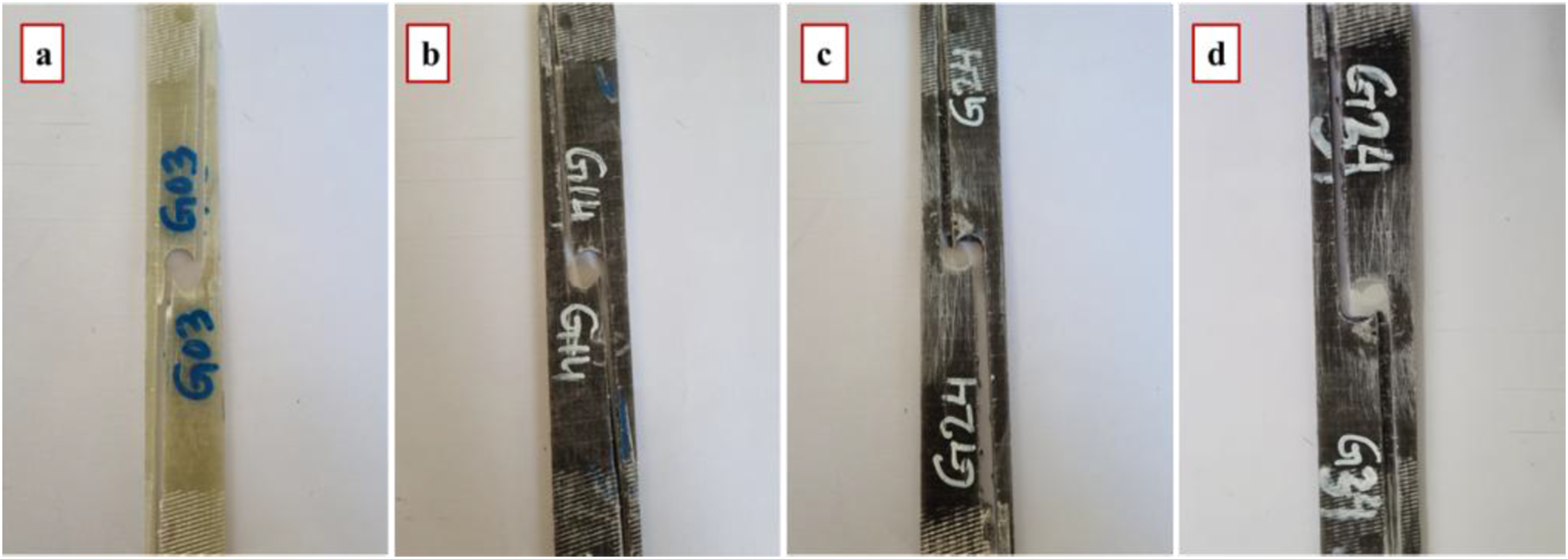
The tensile stress-strain curves for G0, G1, G2, and G3 composites with and without a 10 mm central hole are shown in Figure 11. The tensile behaviour of holed specimens has demonstrated a predictable decrease in strength relative to the non-holed material, in accordance with stress concentration effects. The presence of a hole resulted in a significant decrease in ultimate tensile strength (UTS) and strain at break, demonstrating the adverse effect of the stress concentration. Overall, the average UTS reduction from introducing the hole was between ∼38 and 44% from specimens without a hole. The pure GFRP without filler (G0) showed a UTS of 439 MPa at about 6% strain. In contrast, for the specimen with a hole, the yield strength value was 274 MPa at around 4% strain and thus decreased by about 38% in response to the stress concentration. Stress-strain response of GFRP composites with and without a central hole, illustrating the influence of geometric discontinuity on tensile behaviour.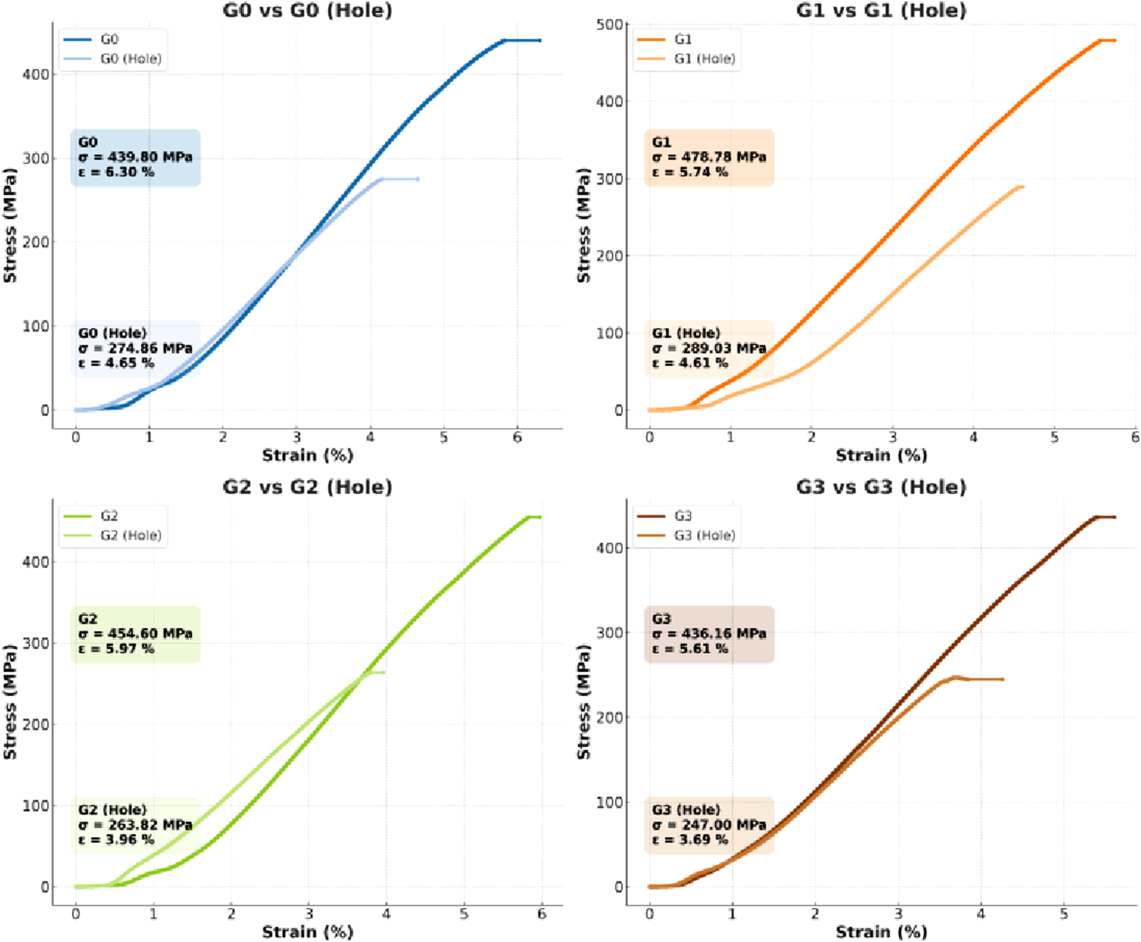
The comparative tensile strength of all neat and B4C-filled GFRP composite samples, with and without a central hole, is presented in Figure 12. The highest tensile strength of 478 MPa was obtained for the composite with 1–10 μm B4C particles (G1) without the hole, and this showed good stress transfer and good fibre-matrix bonding due to the fine dispersion of particles. The corresponding hole specimen was only 289 MPa (∼39% lower). The sample with 20–30 μm particles (G2) had an initial strength of 454 MPa in the intact state and 263 MPa with a hole (a reduction of ∼42%). Similarly, for the composite of 40–50 μm particle size (G3), 436 MPa was obtained without a hole and 247 MPa with a hole (∼43% reduction). The stress-strain curves show a non-linear response in the initial region due to deformation of the matrix and small-scale debonding of the fibre-matrix interface, and then a linear increase related to effective load transfer between the fibre and matrix. The tensile properties of the unholed composites are greater, and the post-peak behaviour is smoother, suggesting slower pull-out of fibres and greater energy absorption. Observed behaviour was also confirmed by the experimentally determined stress concentration factor (Ktexp), which is the ratio of the tensile strengths of unholed and holed specimens. The value of Ktexp was 1.60 for the pure GFRP composite (G0) and 1.65, 1.73, and 1.77 for the B4C-filled GFRP composites, G1, G2, and G3, respectively. The rising trend of Ktexp as B4C particle size increases, shows that Ktexp is more sensitive to localised stress concentration around the hole region. If the larger particles contribute to non-uniformities in the stress distribution, and to early crack initiation, then the reduction in tensile strength due to the presence of these particles would be greater in specimens containing these particles. Tensile strength comparison of neat and B4C-filled GFRP composites with and without a central hole.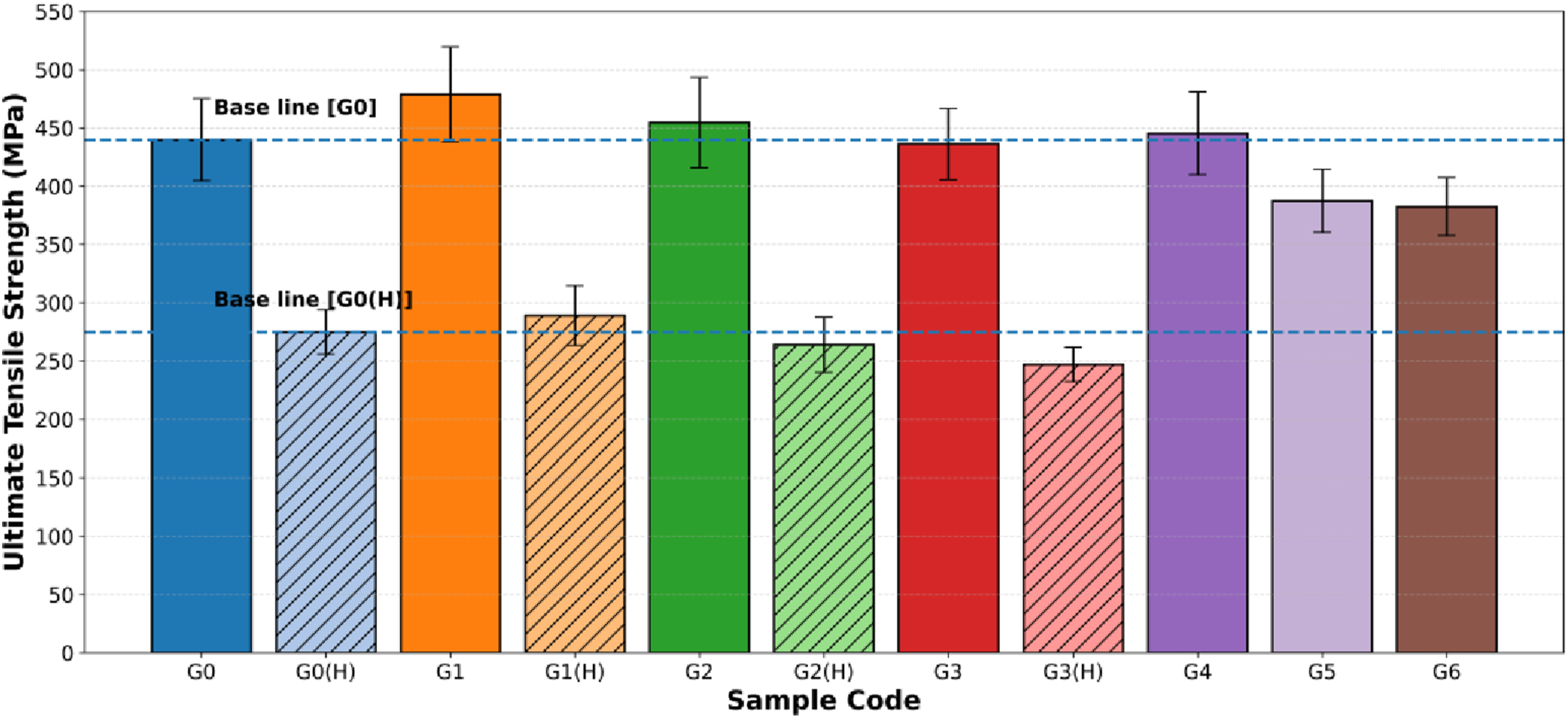
On the other hand, the holed specimens exhibit lower strength and strain with a more pronounced post-peak drop due to the localised stress concentration around the hole and premature crack initiation and brittle failure. This trend indicates the negative effect of the hole on the load-carrying capacity and ductility. However, composites with smaller B4C particles retain more residual strength, which means they have better damage tolerance. This behaviour indicates that small-sized particles help in smoothing out localised stresses along the boundary of the hole, thereby delaying crack initiation and propagation.
The Young’s modulus of GFRP composites with and without a central hole shows a consistent reduction of stiffness caused by the introduction of a geometric discontinuity. The neat composite (G0) has a Young’s modulus of 10.5 GPa, but this Young’s modulus falls to 8.9 GPa for the corresponding holed specimen G0(H). A similar trend is observed for the filled composites, where the modulus of G1 decreases from 10.8 GPa to 9.4 GPa, G2 from 11.1 GPa to 8.7 GPa, and G3 from 10.4 GPa to 8.1 GPa with the introduction of a central hole. This reduction gives confirmation to the negative effect of stress concentration on the elastic response of the composites, as shown in Figure 13. Among all the specimens, we observe that G4 has the highest stiffness with a Young’s modulus of 11.6 GPa, followed by G5 (11.1 GPa) and G6 (11.0 GPa), which highlights the contribution of fibre reinforcement and composite design in increasing the elastic stiffness. Variation of Young’s modulus (GPa) of GFRP composites for different samples. Hatched bars represent holed (H) specimens.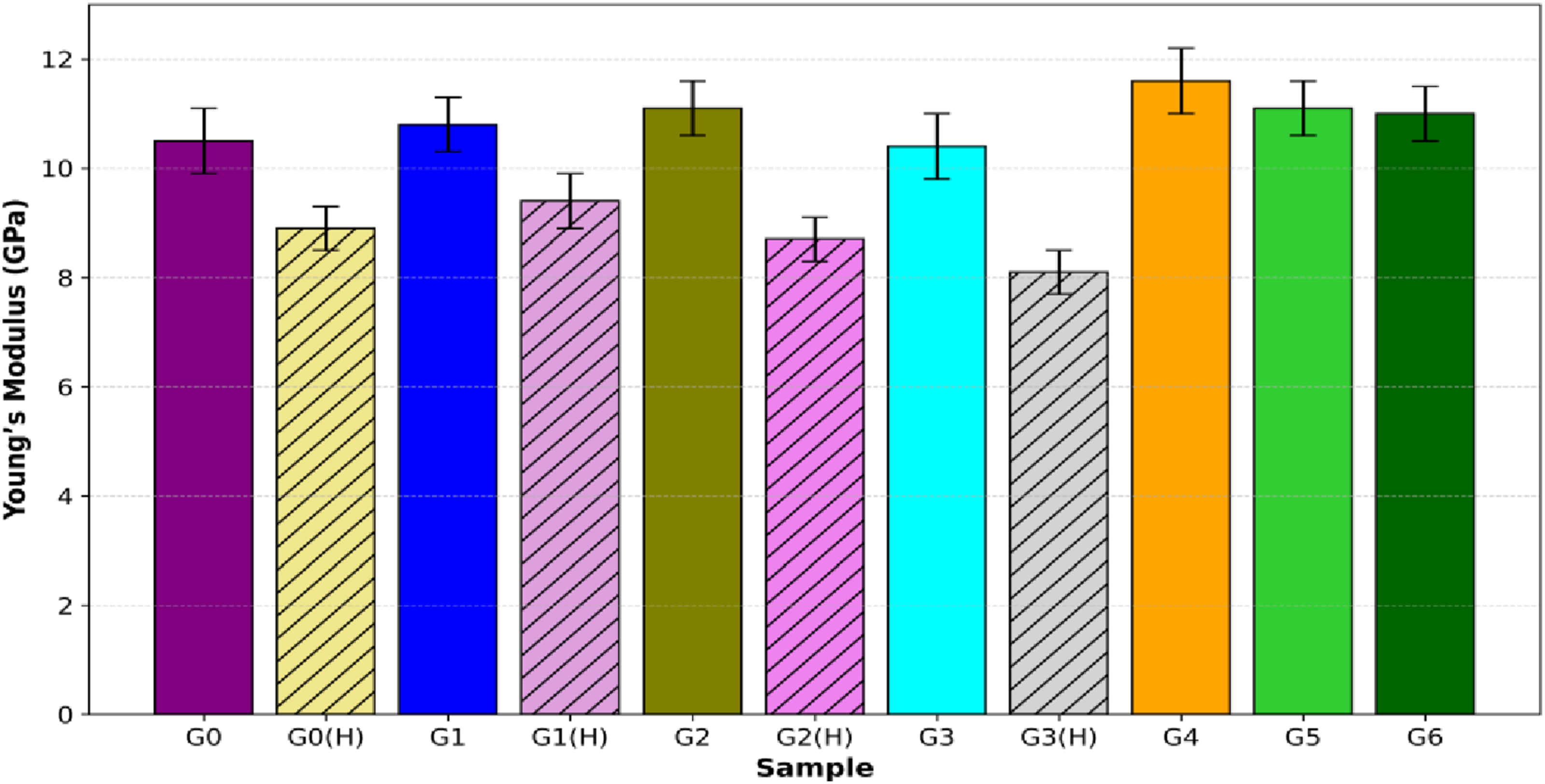
The tensile fracture morphology (Figure 14) of the neat GFRP composite (G0) which exhibits the typical broom-stick-type fracture. This is characterised by the longitudinal separation of fibre bundles in the loading direction, indicating step-wise fracture propagation. At higher magnifications, clear evidence of fibre breakage and multiple broken threads further confirm fibre-dominated failure. The broom-stick fracture is due to a progressive failure mechanism consisting of matrix cracking initiated first, interfacial debonding and gradual fibre fracture under tensile loading. Effective fibre-matrix bonding permits the load to be transferred to the fibres, resulting in longitudinal splitting, fibre pull-out, and splaying as opposed to sudden breakage. This sequential damage evolution promotes energy absorption and results in a fibre-dominated, non-catastrophic fracture morphology. Tensile fracture morphology of the neat GFRP composite (G0) observed under microscopic examination.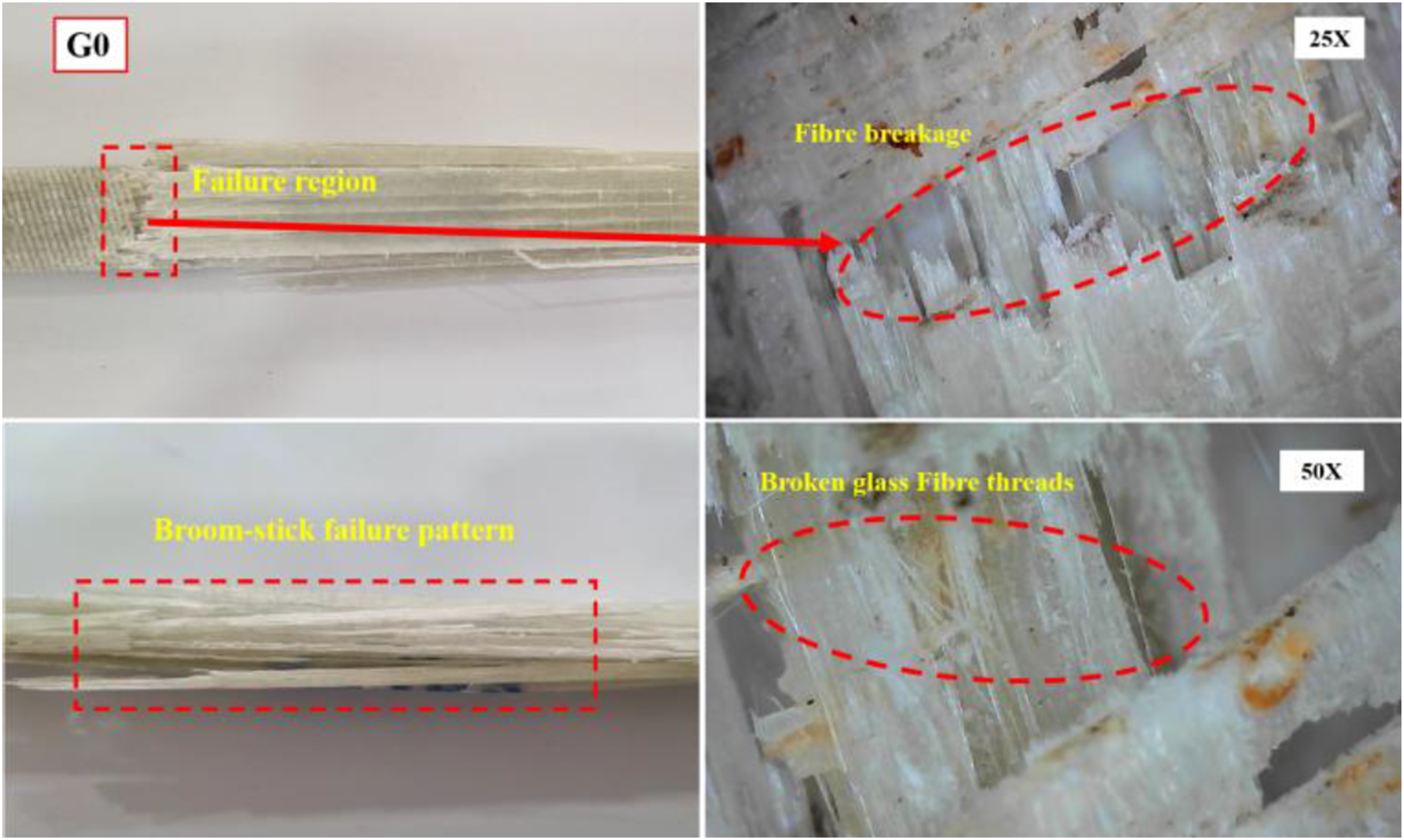
When 1% B4C is added (Figure 15), the fracture behaviour varies with particle size. In G1 (1–10 μm), the existence of long and stable crack paths and gradual cracking of the matrix, as well as the controlled fibre pull-out, are related to the higher tensile and flexural strengths of G1, indicating efficient stress transfer and a more ductile failure mechanism. The finer fillers distribute well within the matrix, improving stress transfer but also encouraging micro-crack growth, which leads to gradual failure. In G2 (20–30 μm), both fibre and matrix-level damage appear. The larger particles enhance load transfer but also act as stress concentrators, causing a mix of fibre rupture and partial pull-out. In contrast, G3 (40–50 μm) undergoes brittle fracture with severe fibre fragmentation, as coarse particles may contribute to localised stress concentration, reduce crack-arresting ability, and trigger sudden fibre failure. Tensile fracture morphology of 1 wt% B4C-filled GFRP composites (G1–G3) observed under optical microscope.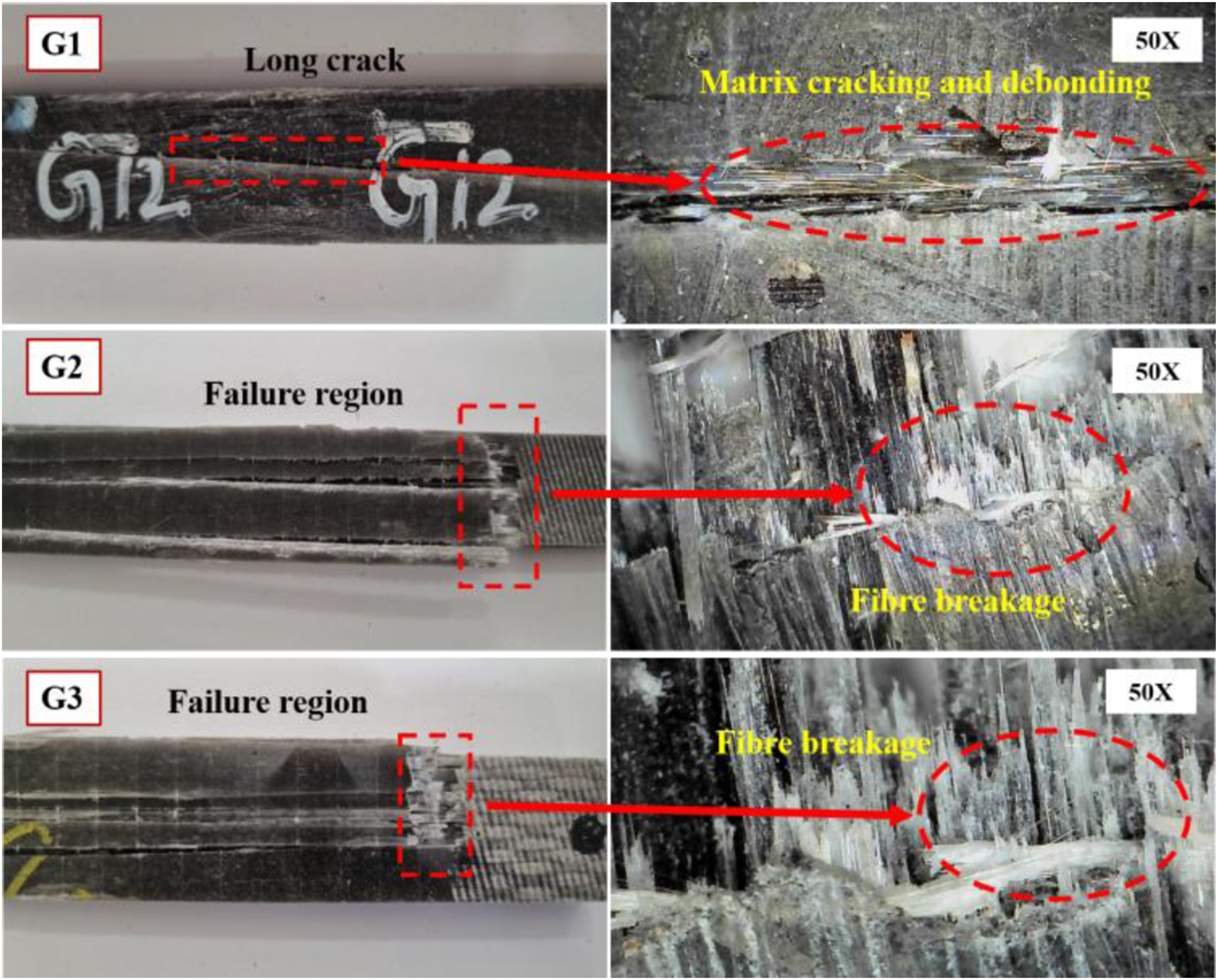
With 2% B4C content (Figure 16), the damage mechanisms become more complex. G4 (1–10 μm) mainly shows fibre breakage, reflecting the ability of fine particles to strengthen bonding and distribute stresses evenly, until the composite fails abruptly. G5 (20–30 μm) demonstrates long cracks and extensive delamination, as intermediate particles weaken interlaminar bonding and create stress accumulation zones, thereby lowering tensile strength. G6 (40–50 μm) displays multiple parallel cracks, fibre pull-out, and matrix cracking, since coarse fillers intensify stress concentration and deteriorate interfacial bonding, leading to premature separation of fibres from the resin. Tensile fracture morphology of 2 wt% B4C-filled GFRP composites (G4–G6) observed under optical microscope.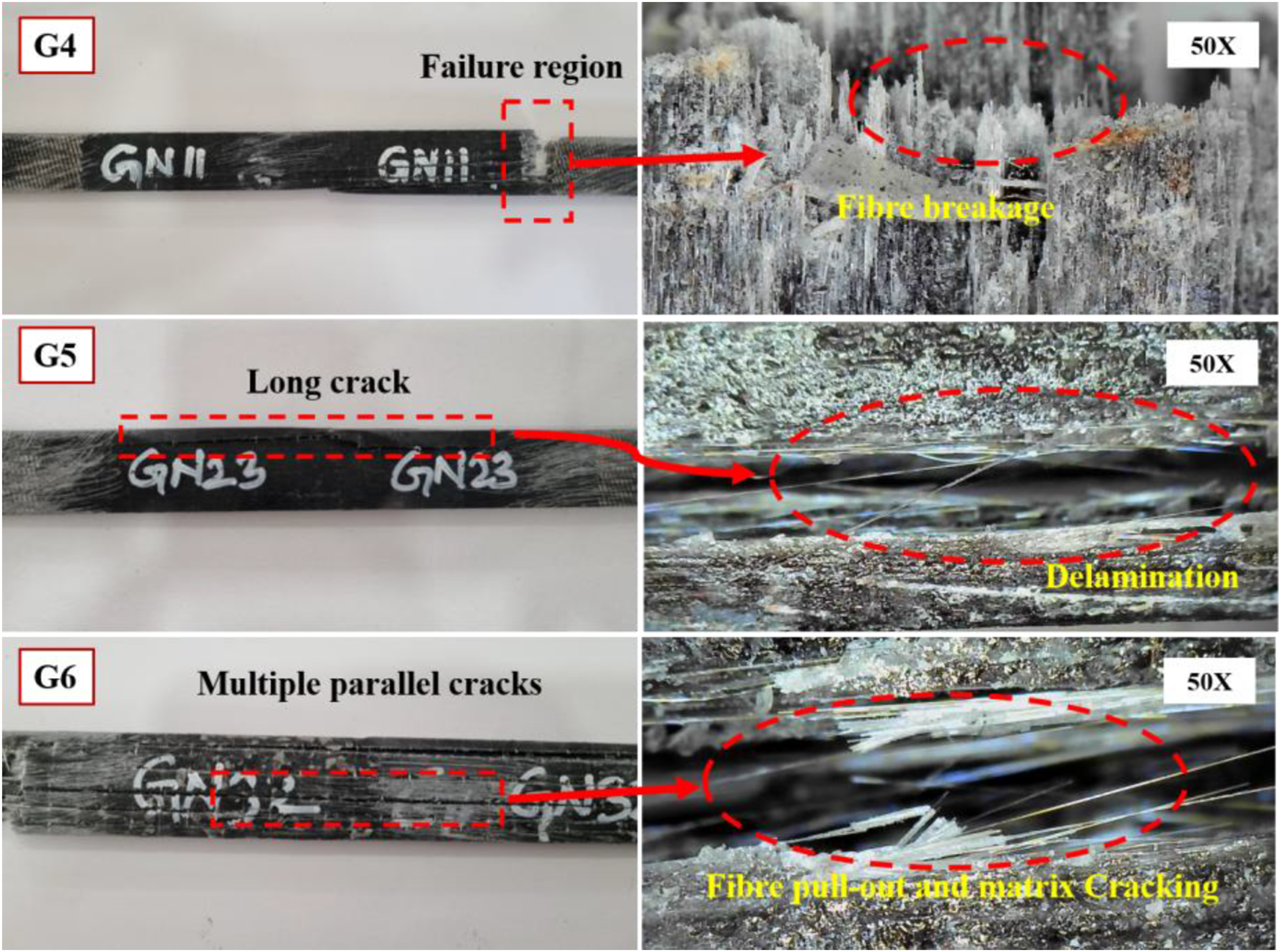
The enhanced mechanical performance of GFRP composites reinforced with finer B4C particles (1–10 μm) is mainly controlled by physical interfacial mechanisms and not by direct chemical bonding. Reducing the particle size increases the effective surface area of B4C and promotes better wetting by the epoxy matrix material during fabrication, resulting in more intimate interfacial contact. This increases wetting, which ensures that the stress transfer and mechanical interlocking between the matrix and filler are effective. Moreover, the finer particles have good load-transfer ability, suppress localised stress concentrations, and delay crack initiation. Conversely, B4C particles with coarser particle size are more likely to interfacial debonding hence influencing as stress concentrators during mechanical loading. Although the present study assesses interfacial integrity through FESEM-based morphological analysis, further investigation using advanced interfacial characterization techniques would provide a more comprehensive understanding of the bonding mechanisms between the B4C particles and the epoxy matrix.
Izod impact test
The Izod impact test was carried out to analyse the toughness of the fabricated composites in terms of absorbing and dissipating the sudden impact energy. The results of this assessment show the effect of the boron carbide filler on the impact performance of GFRP composites. Figure 17 shows the Izod impact strength of all the composite samples compared to the base pure GFRP. The findings show how the integrated boron carbide (B4C) fillers of various particle sizes and 1 wt% or 2 wt% concentration affect the impact strength, the corresponding increase or decrease in performance compared to the neat GFRP. Izod impact strength comparison of neat and B4C-filled GFRP composites with different particle sizes and filler contents.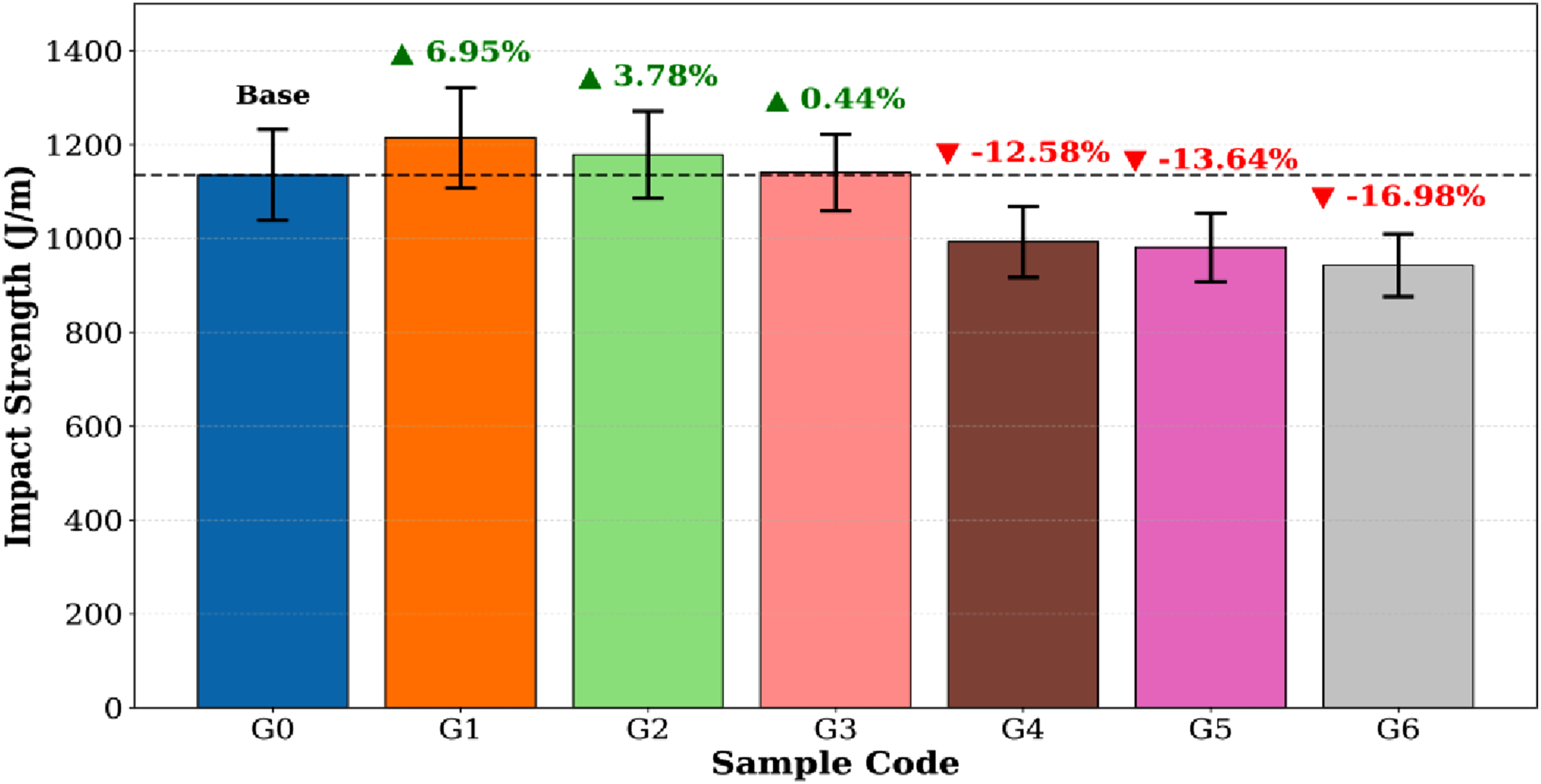
The unfilled composite (G0) had an impact strength of 1136 J/m, which was used as a reference. The optimal improvement was found at 1 wt% filler content for the smallest particle size range (1–10 μm, G1), with the improvement value following 1215 J/m, which is equal to an increase of 6.95% compared to G0. Medium particle size (20–30 μm, G2) and large particle size (40–50 μm, G3) at the same filler content also improved impact strength but to a lesser extent (improvement of 3.78% and 0.44%, respectively). In general, the impact performances decreased as the filler content increased to 2 wt% (G4–G6), while G4 (1–10 μm), G5 (20–30 μm), and G6 (40–50 μm) showed the decreases of −12.58, −13.64, and 16.98%, respectively. These results indicate that the smaller B4C particle sizes at low filler content are more efficient for improving impact resistance. In contrast, a high filler content or large particle sizes can have an adverse effect.
The fractured surface of the neat composite specimen (G0) tested under Izod impact test (Figure 18) shows a clear fibre bundle separation mechanism, such as those observed under 50× magnification. Fracture morphology has wide fibre pull-out and debonding of the adjacent matrix, which points to a low fibre-matrix interfacial bond. The impact energy provided is mostly lost in the cracking of the matrix and separating the fibre bundles gradually due to the absence of a secondary reinforcement. This leads to extensive, large-scale fibre pull-out areas and flowing smooth matrix areas, which are indicative of low crack propagation resistance. Fractured microscopic image of the pure GFRP composite (G0) under the Izod impact test.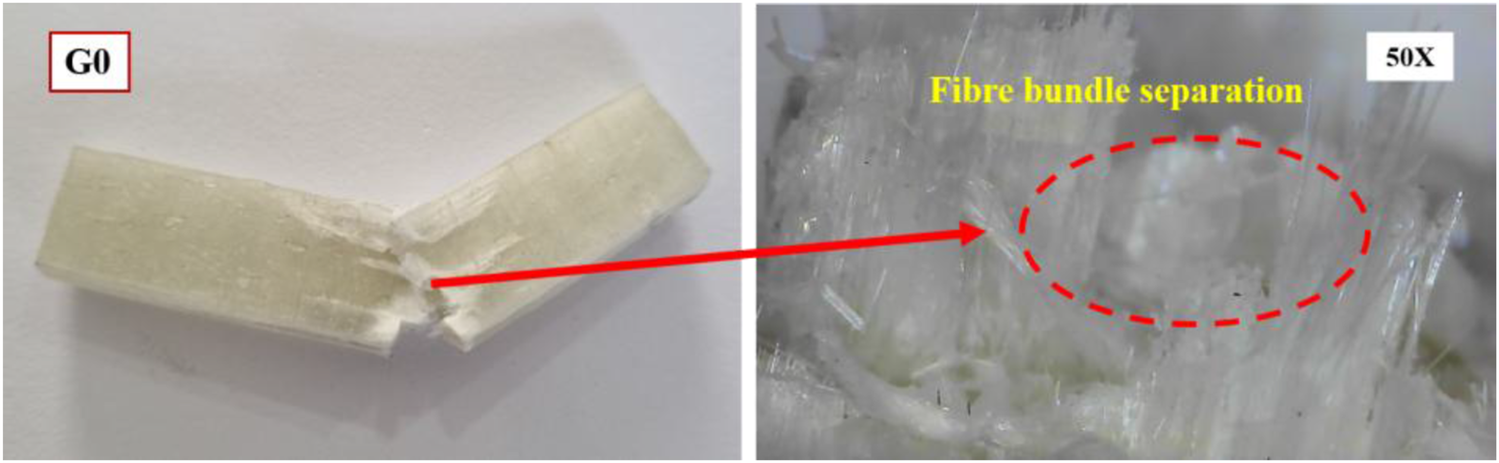
Figures 19 and 20 show the cracked specimens of the Izod impact test reinforced with 1% and 2% B4C particles of different sizes (1–10, 20–30, and 40–50 μm), and the observed specimens under 50× magnification. In the case of the 1% sample (G1), the fibre pull-out of the sample (1–10 μm) is uniform, and the sample exhibits excellent interfacial bonding, demonstrating effective stress transfer and energy absorption. In the G2 sample (20–30 μm), the fracture mode is mixed with medium adhesion, whereas G3 (40–50 μm) shows uneven pull-out and weaker bonding with the cracks spreading along the interface because of the concentration of stress around bigger particles. Conversely, the 2% reinforced specimens have unfavourable fracture behaviour. In G4 (1–10 μm), good pull-out and crack deflection are still observed, but in G5 (20–30 μm), there is partial pull-out with localised matrix cracking, whereas in G6 (40–50 μm), extensive pull-out of the fibre bundles and brittle failure are observed. This situation can be explained by the inferior performance of the composites with 2% filler compared to that of the 1% group due to the agglomeration of particles at high filler content, resulting in low interfacial efficiency, concentration sites, and premature crack initiation. In general, a smaller particle size is preferred to improve the stress distribution and energy absorption; however, higher loading and coarse particles result in brittle fracture attributes and low-impact resistance. Fractured microscopic images of Izod impact-tested GFRP composites reinforced with 1 wt% B4C particles of varying sizes: (a) 1–10 μm (G1), (b) 20–30 μm (G2), and (c) 40–50 μm (G3). Fractured microscopic images of Izod impact-tested GFRP composites reinforced with 2 wt% B4C particles of different sizes: (a) 1–10 μm (G4), (b) 20–30 μm (G5), and (c) 40–50 μm (G6).

The decreasing of the impact strength for the 2 wt% B4C-filled composites can be explained in terms of change in the dominant energy absorption mechanisms during dynamic loading. While fine B4C particles at low filler content (1 wt%) induce crack deflection and enhance matrix constraint, thus energy dissipation by controlled matrix cracking and fibre pull-out, an increase of filler content brings about a different regime of failure. Due to the intrinsically hard and brittle nature of B4C, agglomerated particles at 2 wt% behave as local stress concentration points, which allows rapid initiation and unstable propagation of cracks. These hard inclusions limit plastic deformation of the epoxy matrix and inhibit energy-absorbing mechanisms such as fibre pull-out and interfacial debonding, resulting in premature brittle fracture. As a result, the degradation of impact strength in increased filler content is controlled mostly by stress concentration and diminished energy absorption due to matrix influence as opposed to reinforcement-controlled toughening.
Based on the combined tensile and impact performance, the composite with 1 wt% B4C particle size of 1–10 μm (G1) is found to be the optimal formulation in the current study. Specifically, the presence of long and stable crack paths and uniform fibre pull-out seen in G1 is directly related to its highest measured impact strength (1215 J/m) and thus suggests a more ductile and energy-absorbing fracture mechanism compared to the brittle and short-crack-dominated failure seen in higher filler-content composites. Compared to neat GFRP, this composition has 8.9% higher ultimate tensile strength, 6.95% higher impact strength, as well as enhanced damage tolerance and interfacial integrity, which proved the fine B4C particle’s effective function at low filler content.
Morphological analysis of fractured samples
The impact fracture surface SEM images of neat GFRP composites without B4C filler are presented in Figures 21(a) and 21(b) at 1000× magnification. The images reveal typical features such as pull-out of the fibre, marks of river lines, cusps, and debonding of the fibre-matrix. These characteristics show poor interfacial bonding between fibre and matrix, and the cracks propagate easily along the interface, leading to brittle fracture under impact. SEM micrographs of impact-fractured surfaces of neat GFRP composite (G0).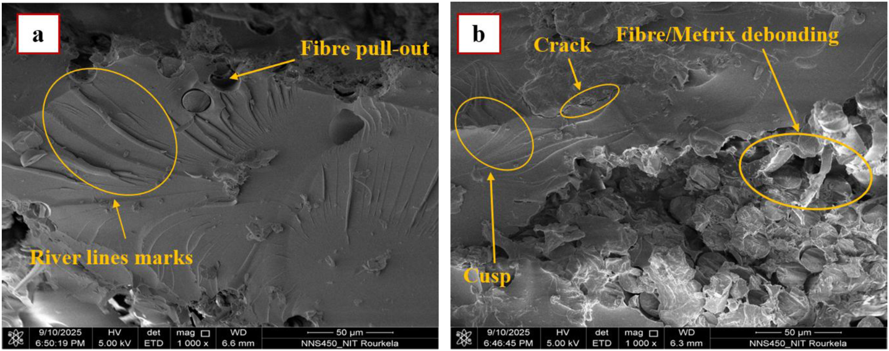
When the filler is 1% B4C particle, the fracture morphology is drastically changed. In the G1 sample (Figures 22(c) and 22(d)), with fine B4C particles of 1–10 μm, uniformly distributed fillers can be observed. The fine particles have the effect of increasing stress transfer between the matrix and fibres, thereby enhancing crack resistance. Although micro-cracking is visible, the fracture is more energy absorbing because effective crack deflection and stress redistribution are achieved by the fillers. But there are some chipping and localised fibre fractures with interfacial debonding shown in the sample SEM image. SEM micrographs of impact-fractured surfaces of GFRP composites reinforced with 1% B4C particles of varying sizes: (c, d) G1 sample; (e, f) G2 sample.
In contrast, the G2 sample (Figures 22(e) and 22(f)), which was reinforced with relatively larger 20–30 μm B4C particles, shows fibre-matrix debonding, rupture of matrix and fibre pull-out. Although these larger-sized particles also serve a role in load transfer, they act as stress concentrators and create localised weak zones that can cause them to break. This means that the fracture mode is mixed, with fibre rupture and matrix cracking. However, the presence of these particles still leads to enhanced impact resistance with respect to the neat composite since the particles hinder direct crack propagation.
On the other hand, the 2% B4C composites (G4 and G5) show noticeable defects that degrade the impact resistance. Figures 23(g) and 23(h) show the fracture surface in the G4 sample containing fine 1–10 μm particles, which showed river line signs, long cracks, and notable agglomeration of B4C particles. These inclusions impair proper stress transmission and act as crack initiation sites, and enhance brittle fracture. The G5 sample (Figures 23(i) and 23(j)) reinforced with larger 20–30 μm particles exhibits even more severe damage with extensive agglomeration of B4C, voids, fibre-matrix debonding and broken fibres. Aggregation of coarse particles and voids weaken the fibre-matrix interfacial strength and thus impacts the energy absorption of the composite. These flaws may propagate the cracks through the weak areas, which could be the reason for the poor performance of 2% B4C composites compared to the 1% counterpart. SEM micrographs of impact-fractured surfaces of GFRP composites reinforced with 2% B4C particles of varying sizes: (g, h) G4 sample and (i, j) G5 sample.
From this analysis, it could be seen that the better performance of the 1% B4C composites is due to fine and well-distributed particles, which improve the interfacial bonding, stress transfer, and crack deflection. Conversely, in 2% filled composites, the excess particles are more likely to agglomerate, form voids and increase stress concentration, resulting in early crack nucleation and brittle fracture. Moreover, the B4C addition at low filler content shows a beneficial effect on mechanical properties, whereas the microstructural defects at higher filler content are found to counteract the reinforcing effect.
The FESEM image (Figures 23(g)–(j)) clearly shows the pronounced agglomeration of B4C particles in the 2 wt% composites, along with micro-voids and extensive crack networks. Such agglomerated regions become the localisation points of stress, which facilitates crack formation and enhances crack propagation along the fibre–matrix interface. The existence of interconnected cracks in the area of B4C clusters verifies that agglomeration has a predominant role in the deterioration of mechanical performance at a high filler volume.
Tribology testing
Measured tribological responses of GFRP composite samples (G0–G3) under varying test conditions.
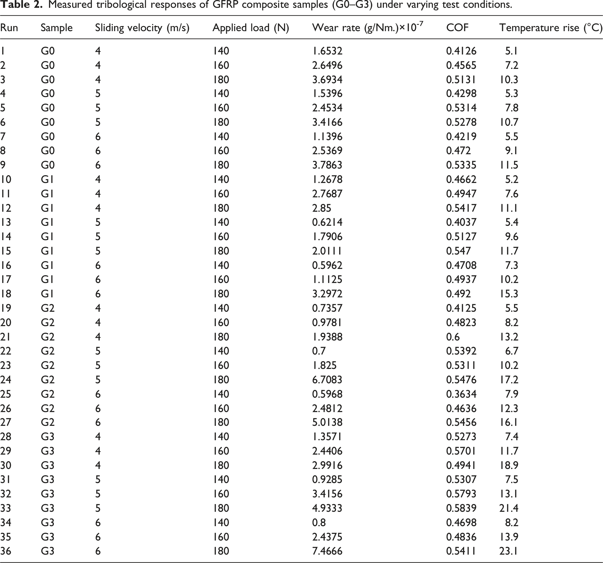
The wear testing results for the four composite samples, G0, G1, G2, and G3, demonstrate different tribological performances under varying loads (140, 160, and 180 N) and sliding velocities (4, 5, and 6 m/s). The main findings are revealed through analysis of the wear rate, coefficient of friction, and temperature rise.
The wear rate results (Figure 24) show a more complex interaction between load and velocity. For the G0 sample, wear increases steadily with both parameters, confirming the lower wear resistance of the unfilled composite. It is evident that wear rate is affected by operating conditions; load is more effective than velocity, as shown in the results of GFRP composites under various loads and velocities. Optimum performance is obtained at G1 with 140 N and 6 m/s, at which the wear rate is as low as 0.5962 × 10⁻⁷ g/Nm, indicating the protective action of fine B4C particles. Conversely, the maximum wear rate in the worst case of G3 at 180 N and 6 m/s is 7.47 × 10⁻⁷ g/Nm, which is almost 10 times higher. Overall, increasing load consistently raises the wear rate for all samples. Additionally, velocity has a secondary effect that becomes significant at higher loads, especially for G2 and G3, due to particle fragmentation and abrasive interactions. Wear rate heatmaps of GFRP composites (G0–G3) under varying loads and sliding velocities.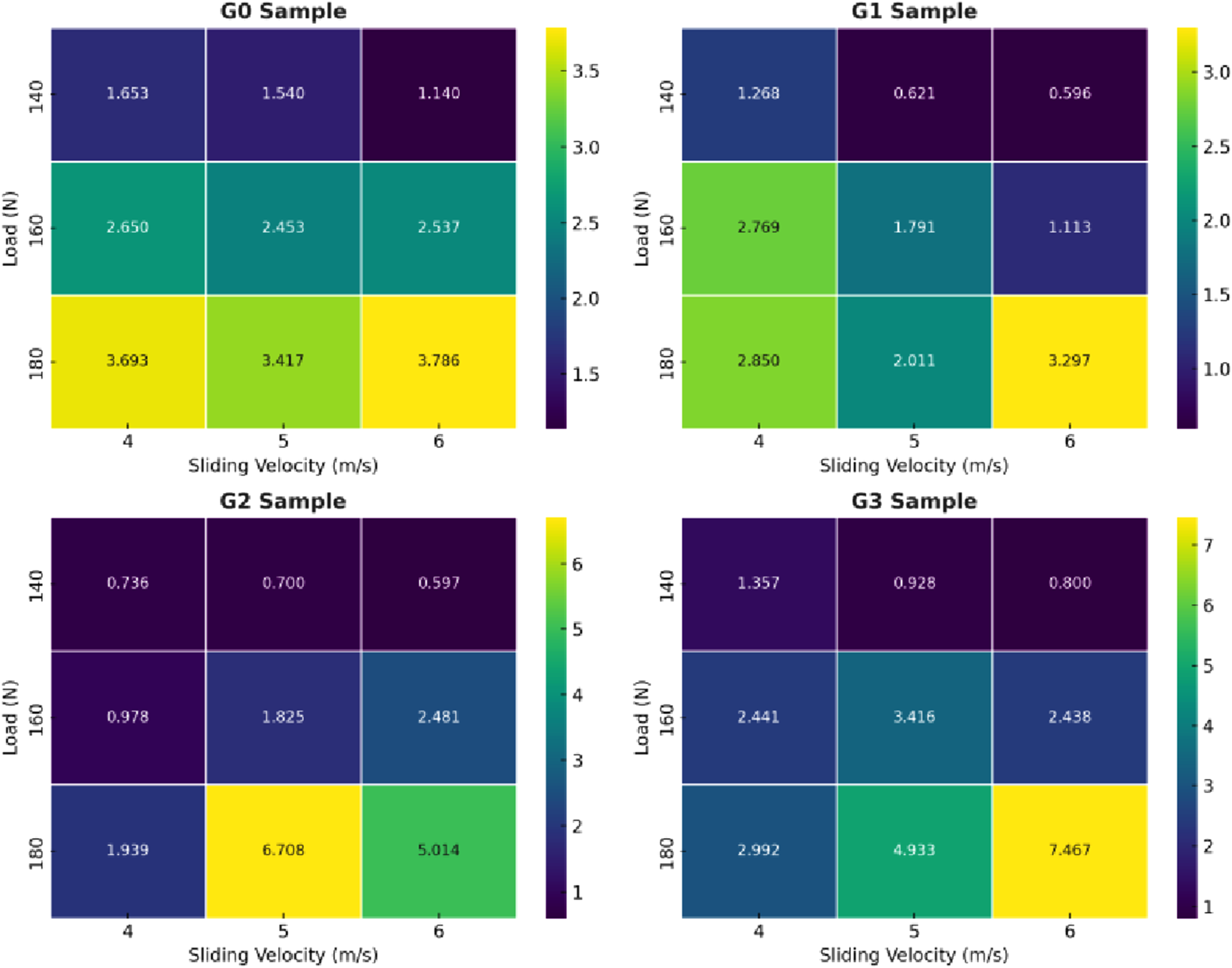
The coefficient of friction (Figure 25) is strongly dependent upon the load and velocity. The minimum COF is reported for the G2 sample, having 140 N and 6 m/s speed, with approximately 0.3634. On the other hand, the maximum COF is obtained for G2 at 180 N and 4 m/s, which is 0.60, due to the severe micro-abrasion induced by larger B4C particles. This interpretation is further supported by the FESEM observations of the worn surface of G2 (Figure 30), which show prominent abrasive grooves, fibre-matrix debonding and embedded wear debris, in confirmation of the predominance of micro-abrasive wear mechanisms that are responsible for the high coefficient of friction. Coefficient of friction heatmaps of GFRP composites (G0–G3) under different loads and velocities.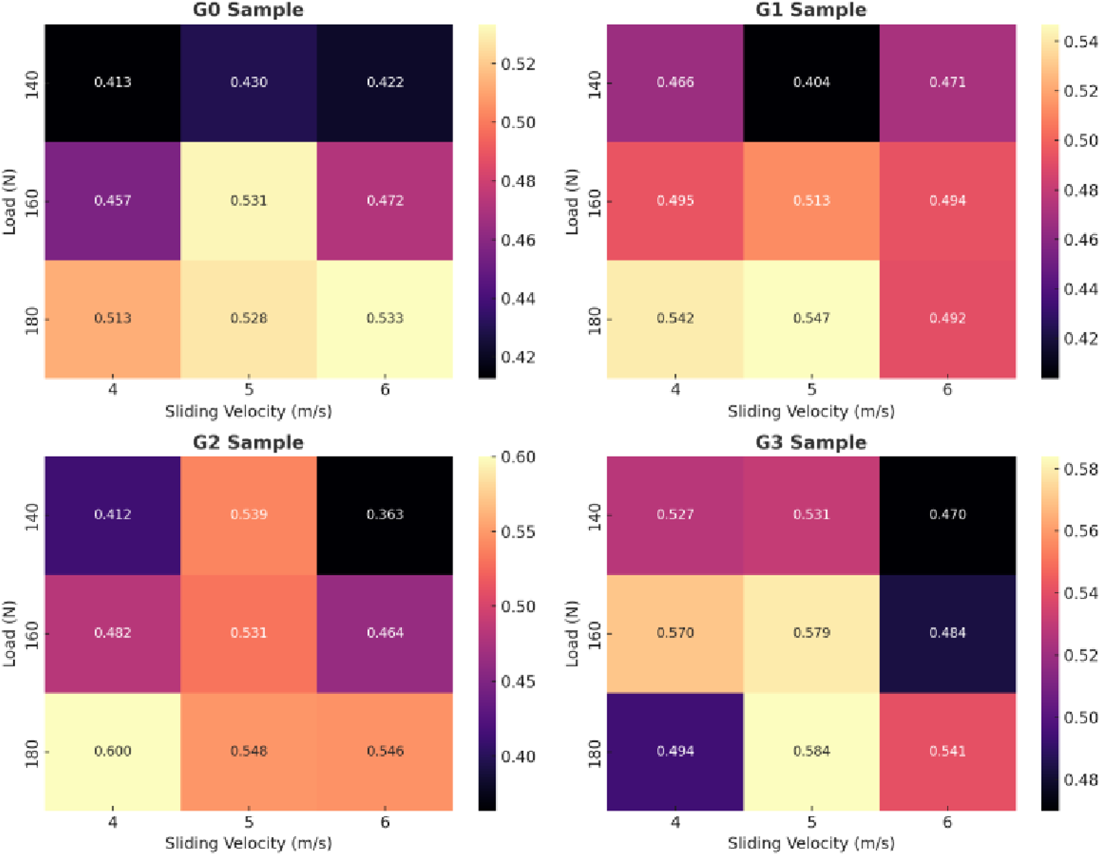
It is found that the COF increases monotonically with load for all the samples, whereas velocity has relatively less effect and is noticeable only at higher loads. These results are consistent with previous research on GFRP composites, where load was found to be the controlling factor on COF for dry sliding conditions.
The temperature increase (Figure 26) in the composites is found to be directly proportional to load and sliding speed, and load is found to have a greater effect on the temperature increase. The minimum temperature rise results shown in the G0 sample at 140 N load and 4 m/s velocity are approximately 5.1°C. On the other hand, G3 produces the highest temperature rise at 180 N and 6 m/s, which is approximately 23.1°C, resulting in the maximum temperature increase due to increased interfacial friction and abrasion caused by the bigger size fillers. Generally, temperature increases with load. Additionally, the effect of velocity is significant only at higher loads, especially for G2 and G3, where the larger B4C particles contribute to micro-cutting and heat generation. These findings are consistent with previous tribological studies on composites, which also identify load as the main factor influencing temperature rise during dry sliding. Temperature rise heatmaps of GFRP composites (G0–G3) under different loads and velocities.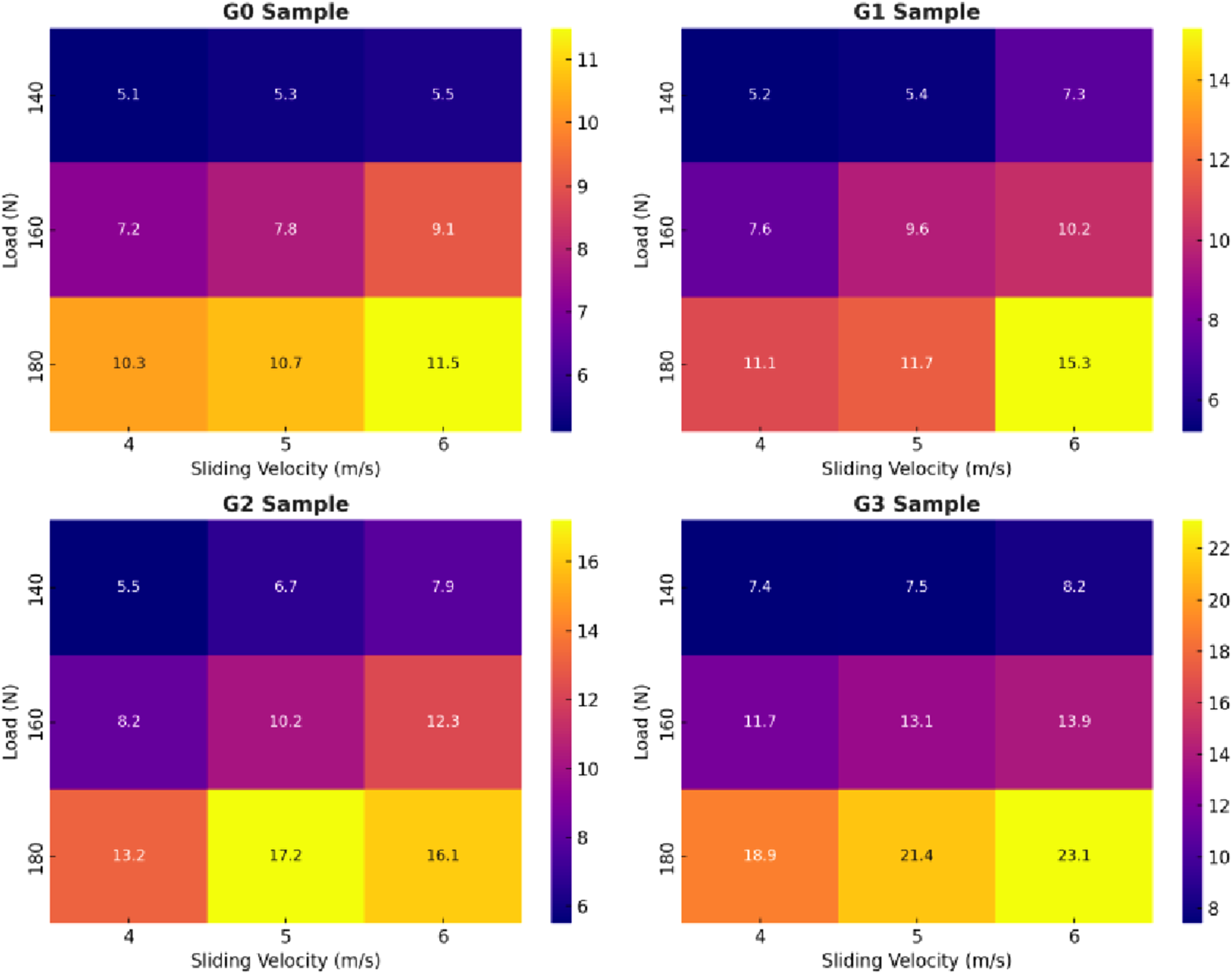
The observed decoupling between wear rate and coefficient of friction can be attributed to competing tribological mechanisms. In composites with fine B4C particles (G1), the filler behaves mainly as a load-bearing phase, contributes to the improvement of surface hardness, and forms a compact and stable tribolayer. This tribolayer prevents the underlying matrix and fibres from degradation, and therefore, a low wear rate is achieved with the severe material removal being suppressed. However, the existence of hard ceramic particles and compacted debris at the sliding interface is contributing to moderate interfacial shear resistance due to mild third-body interactions, resulting in a moderate coefficient of friction. In contrast, the formation of unstable tribolayer, micro-cutting, and abrasive interactions, which promote coarser B4C particles, is increasing the wear rate and friction. These results indicate that wear resistance and frictional behaviour are influenced by different, and sometimes competing, mechanisms, with fine B4C particles optimising wear protection rather than friction minimisation.
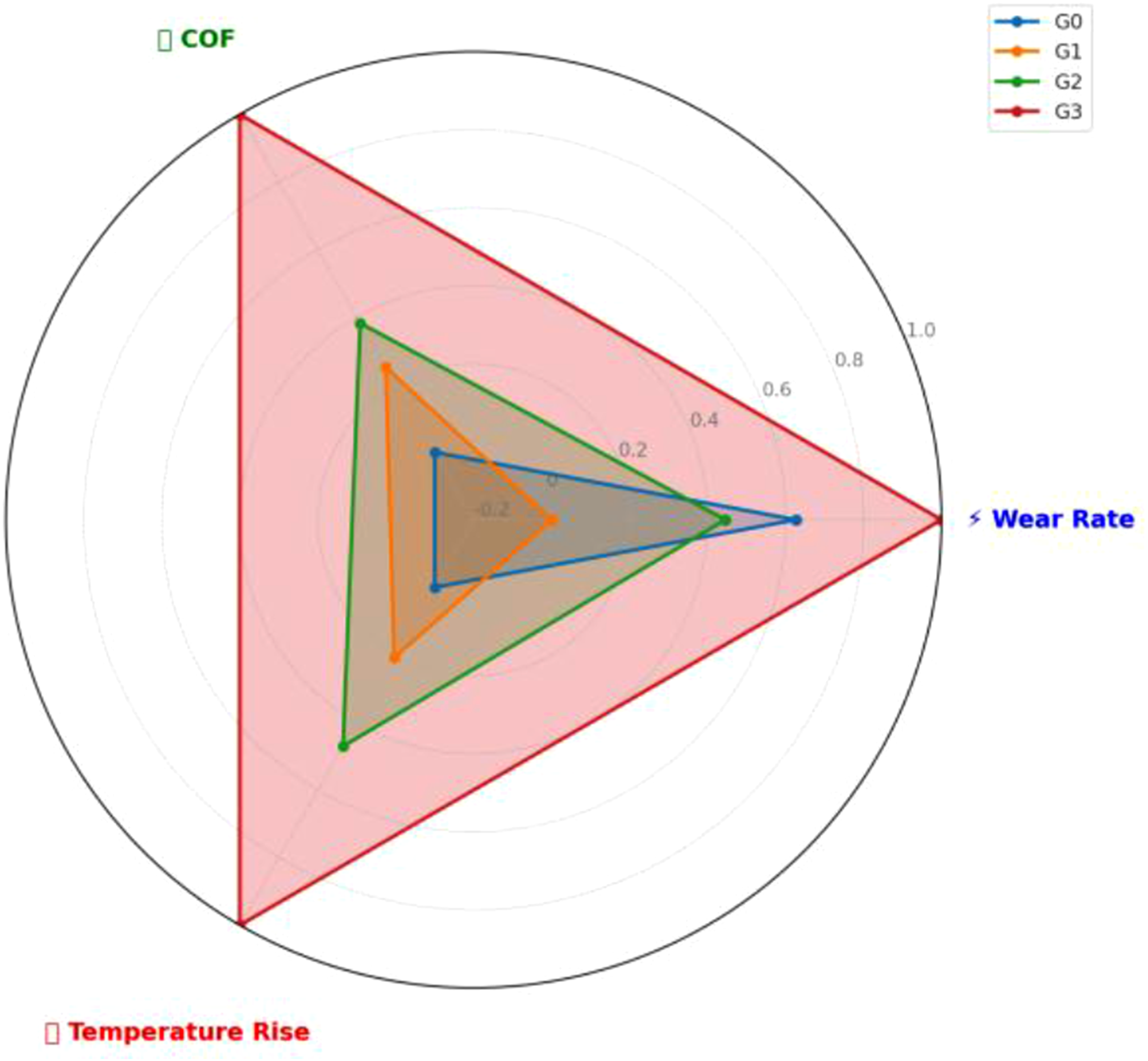
The radar plot (Figure 27) compares the performance of composite samples G0–G3 in terms of Wear Rate, Coefficient of Friction, and Temperature Rise. For the radar chart comparison, the average values of Wear Rate, Coefficient of Friction, and Temperature Rise were calculated for each sample (G0–G3) across all test conditions (three loads × three velocities). These average values were then normalised using min-max normalisation. Performance radar of GFRP composites (G0-G3) showing normalised wear rate, coefficient of friction, and temperature rise. The values are normalised using min-max normalisation, where 0 represents the best performance and 1 represents the worst performance among the samples. The average values (across all 9 runs per sample) and their normalised values.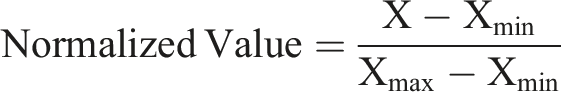
The radar chart is used to compare the tribological performance of the G0–G3 composites. The unfilled composite (G0) shows the second-highest wear rate. However, for the other two parameters, COF and temperature rise, it records the lowest values, indicating weak wear resistance but relatively stable friction and reduced heat generation. The best balance is found in the G1 sample, where the wear rate is lowest, moderate COF and the temperature rise, indicating that the fine B4C fillers have a protective effect. The G2 composite shows a moderate performance, as there are slight wear and an increase in temperature, but slightly higher COF, because of the micro-cutting of more discrete particles. On the contrary, G3 has the highest radar profile, the highest wear rate, COF, and temperature increase, which proves that the larger B4C filler size increases frictional interactions and heat generation under harsh conditions. In general, the radar chart indicates that G1 is the most tribologically stable. In the meantime, G3 is the least favourable in terms of response, and G0 still has poor wear resistance compared with G1 and G2, but has the lowest COF and a temperature rise among all.
The lower wear rate and stable coefficient of friction obtained for finer B4C-filled composites can be attributed to a stable tribo-layer formation and suppression of severe abrasive ploughing. Uniformly dispersed fine particles are responsible for controlled debris formation and lower interfacial shear stress, leading to higher sliding stability. Conversely, coarse particles and higher filler content promote third-body abrasion and surface fragmentation.
Although the present study focuses on dry sliding conditions, the tribological performance of B4C-filled GFRP composites is expected to be influenced by environmental factors, such as moisture and lubrication. The presence of moisture or a lubricant usually reduces direct contact between the composite surface and the counter face, and this may reduce both the wear rate and coefficient of friction for all compositions. Under such conditions, the sensitivity of friction to B4C particle size may be reduced because of the dominant role of the interfacial fluid film. However, composites containing finer B4C particles are anticipated to retain their relative performance advantage due to more uniform load sharing and greater surface stability, whereas coarser or agglomerated particles may lead to less stable sliding behaviour. Consequently, although the environmental conditions may alter the absolute values of wear and friction, the overall ranking of tribological performance as a function of the B4C particle size is expected to be adjusted very little. Future studies with controlled humid and lubricated testing conditions would further increase the applicability of the present findings.
Surface morphology analysis of wear-tested composite samples
A field emission scanning electron microscope (FESEM) was used to examine the worn surfaces of composite samples after the pin-on-disc wear test. The high-resolution FESEM images taken at magnifications of 250×, 1000×, and 5000× were used to provide detailed information about surface morphology and wear-induced damage characteristic features. Commonly observed phenomena included matrix deformation, fibre fracture, pull-out, interfacial debonding, delamination and transfer film formation on the wear tracks.
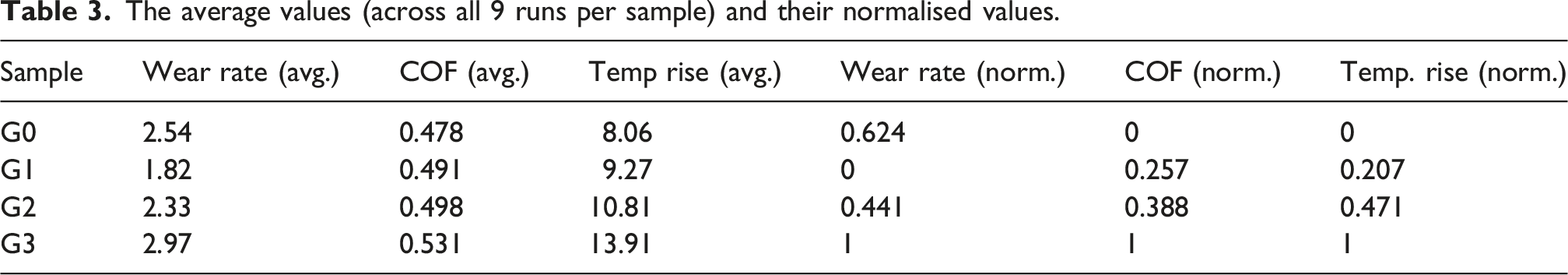
The FESEM micrographs of the worn neat GFRP composite (Figure 28) clearly show the characteristic wear features developed during sliding against the steel counter face. At 250× magnification (Figure 28a), the surface is characterised by significant fibre-matrix debonding and fibre pull-out, which are oriented in the direction of sliding, suggesting a high level of shear-induced wear. The fracture of the fibre-matrix interface is seen at 1000× magnification (Figure 28b), indicating that the interfacial debonding and fracture of the fibres occur due to repeated frictional loading. Abrasive grooves and small wear debris can easily be observed at 5000× magnification (Figure 28c), indicating that we have a mixed wear of adhesive and abrasive wear, and localised smearing of the matrix and fibre breakage. All these characteristics are pointers to the fact that the neat GFRP suffered extreme surface degradation owing to severe adhesive interactions and high contact stress during the wear process. FE-SEM micrographs showing worn surface morphology of neat GFRP composite at different magnifications.
The worn surface morphology of the 1 wt% B4C (1–10 μm)-filled GFRP composite is shown in Figure 29, and it clearly shows that it has a moderate wear behaviour. There are well-developed sliding marks and fine abrasive grooves on the surface, and minor damage to the matrix. During sliding, fibres are still largely intact and well bonded to the matrix, which implies that during interfacial adhesion, and load sharing is better. The fact that there is compacted fine debris indicates a stable tribological response wherein there is controlled material removal. Morphological analysis confirms microscopically that with the addition of 1 wt% B4C particles, a smooth and uniform worn surface is obtained, and the wear process is controlled mainly by a mild abrasive wear mechanism. The improved wear resistance observed in composites reinforced with fine B4C particles may also be associated with the possible formation of a stable third-body layer (tribo-layer) during sliding conditions. This compacted wear debris layer can reduce direct surface interaction and enhance wear stability. However, this mechanism was not directly characterised in the present investigation. FESEM micrographs of the worn surface of G1 composite (1 wt% B4C, 1–10 µm).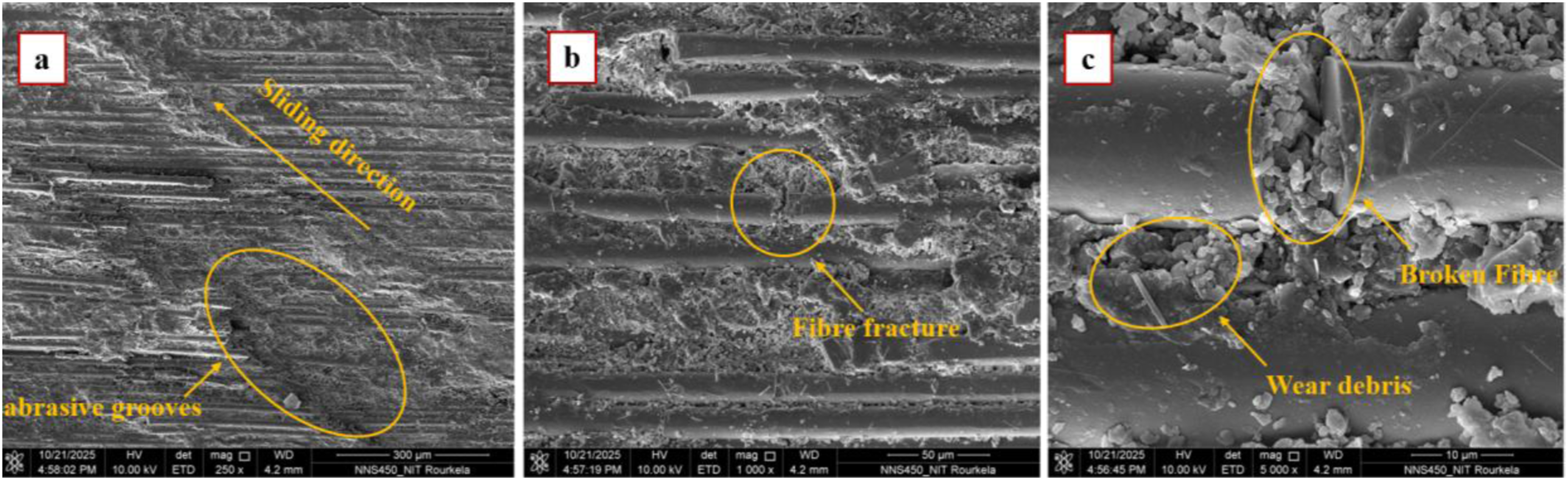
The worn surface morphology of the filled GFRP composite (1 wt% B4C, 20–30 μm) in G2 is represented in Figure 30. The surface shows clear signs of fibre breakage, fibre-matrix debonding and lots of exposed reinforcement, which shows a localised failure of interfaces during sliding. Broken fibres and accumulated wear debris are visible, suggesting mechanical fragmentation under frictional stress. The large-magnification picture depicts eroded surfaces of the fibres with some evidence of the matrix adhesion, suggesting the partial protection of the filler particles. The general morphology of the FE-SEM image indicates a combined wear mode of adhesive-abrasive, with the erosion of the matrices and fibre fracture playing a role in eroding the material and retaining a reasonable state of the surface. FESEM micrographs of the worn surface of G2 composite (1 wt% B4C, 20–30 µm).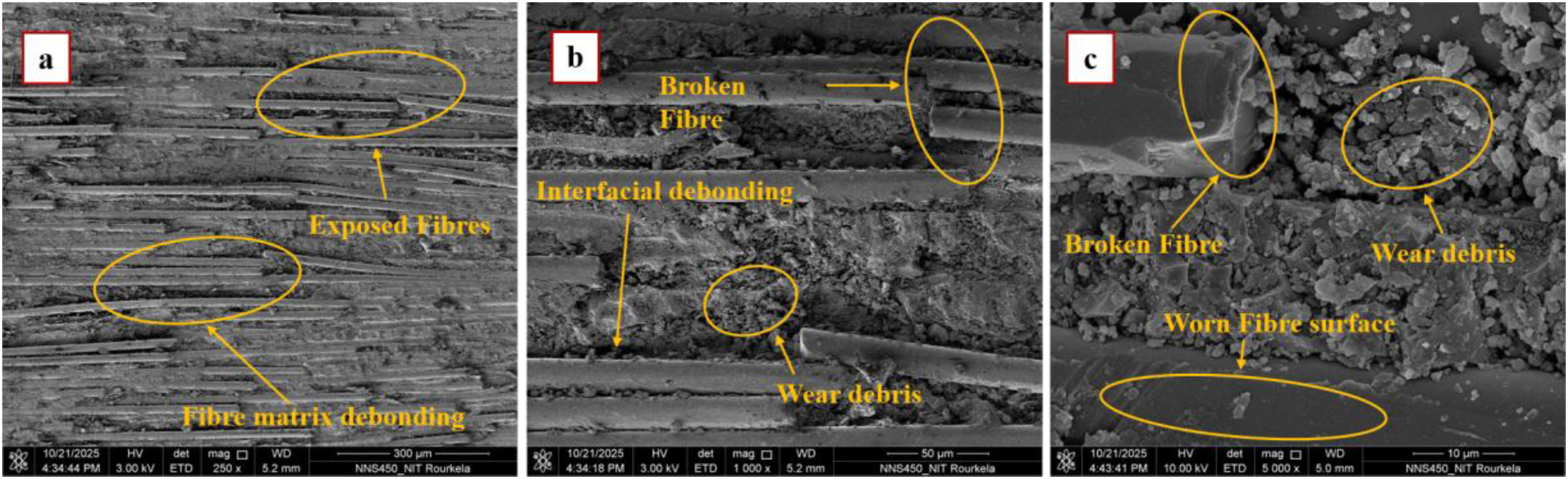
The worn surface morphology (Figure 31) of the G3 sample (1 wt% B4C, 40–50 μm)-filled GFRP composite, which had the highest wear rate, coefficient of friction, and temperature rise during testing. A low-magnification image reveals that the surface of the matrix is very deformed and rough, which implies very strong sliding contact and thus the severe removal of the material. The evidence of matrix smearing, cracking and delamination indicates that the epoxy matrix is highly adhesively interacting and also thermally softening of the epoxy. The formation of transfer film and the build-up of surface debris are seen at higher magnifications, indicating the unstable tribo-layer behaviour at high temperature and frictional conditions. The magnified image reveals fibre-matrix debonding and fractured fibres, which establish interfacial failure and brittle fracture due to recurrent shear loads. FESEM micrographs of the worn surface of G3 composite (1 wt% B4C, 40–50 μm).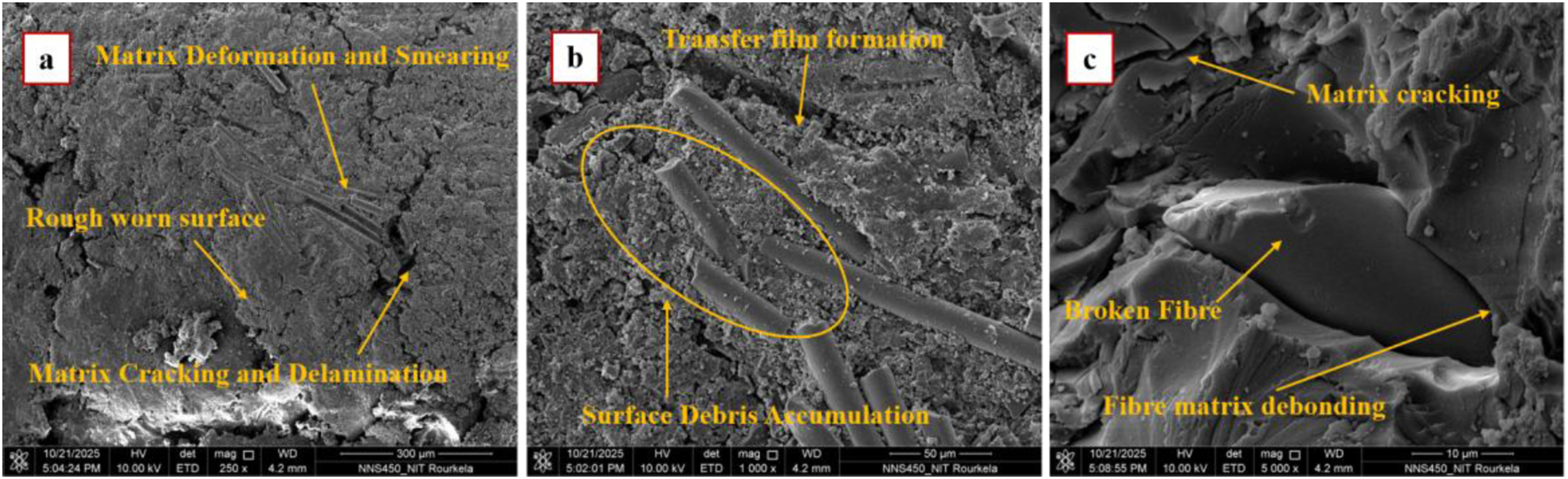
The morphological evidence supports the wear resistance ability of the B4C filler in the presence of finer particle size (1–10 μm), such as G1, by improving interfacial bonding, load distribution, debris stability, and suppressing extensive fibre pull-out. The larger particles (20–30 and 40–50 μm) in G2 and G3 caused stress concentration and interfacial weakening, resulting in increased surface damage and leading to accelerated material removal during sliding. Thus, the G1 composite exhibited the most stable and uniform wear morphologies, which confirmed the positive effect of fine B4C fillers in enhancing the tribological properties of GFRP composites.
Overall, the combined results from the mechanical, tribological and microstructural analyses showed that the B4C particle size controls the transformation from effective reinforcement and wear stabilisation to agglomeration-induced damage in GFRP composites.
Conclusion
Based on the experimental study of B4C-filled GFRP composites with different particle sizes and contents of filler, the following conclusions can be drawn: ▪ The mechanical response of GFRP composites strongly depends on the particle size of B4C, where the finer particles at low filler content result in effective load transfer and enhanced tensile and impact characteristics. The most favourable response was observed with composites reinforced with 1 wt% B4C, particle size range (1–10 μm) showing an increasing ultimate tensile strength of about 8.9% and impact strength of about 6.95% over neat GFRP. ▪ Increasing filler content to 2 wt% causes particle agglomeration and formation of micro-voids, thus reducing ductility and causing premature failure, especially for coarser particle sizes. ▪ Holed tensile specimens show a predictable decrease (∼38–44%) in strength as well as reasonable damage tolerance, which indicates the applicability of fine-particle-filled composites under stress-concentrated conditions of machining and assembly. ▪ Tribological performance is strongly affected by the particle size, whereby fine B4C particles aid in a low wear rate, improved surface stability, and suppressed severe abrasive damage. Among all compositions, the composite reinforced with 1 wt% fine B4C particles (1–10 μm) exhibited the most favourable wear performance, achieving nearly a twofold reduction in wear rate compared with unfilled GFRP under severe sliding conditions, whereas composites containing coarse B4C particles showed accelerated wear and higher frictional heating due to increased abrasive interaction and surface degradation. ▪ SEM analysis shows that particle size-controlled dispersion is a critical factor affecting interfacial integrity, fracture behaviour and wear mechanisms in B4C-filled GFRP composites, with the fine particles at 1 wt% allowing for uniform dispersion, strong fibre-matrix bonding, crack deflection and stable tribo-layer formation, whereas increased particle size and filler content result in agglomeration-induced interfacial failure and severe surface damage.
This work highlights a qualitative relationship between the mechanical and tribological behaviour of particulate-filled GFRP composites, providing practical insight into the trade-off between structural integrity and tribological durability for advanced engineering applications. These insights highlight the importance of carefully controlling filler size and loading to tailor the performance of composites for next-generation high-performance material systems. The findings also further emphasise the need for controlled filler dispersion at low concentrations to realise potential performance benefits, while not experiencing the detrimental effects of excessive loading.
Footnotes
Acknowledgements
The authors Shubhra Vishwas and Yugendra Kumar Sahu express their sincere gratitude to the All-India Council for Technical Education (AICTE), Government of India, for providing fellowship support. The authors are also thankful to the National Institute of Technology (NIT) Rourkela for providing access to SEM and FESEM facilities, the Central Institute of Petrochemicals Engineering & Technology (CIPET), Raipur, for facilitating tensile and impact testing, and the Department of Mechanical Engineering, Guru Ghasidas Vishwavidyalaya (GGV), Bilaspur, for providing the pin-on-disc wear testing facility.
Author contributions
Funding
The authors received no financial support for the research, authorship, and/or publication of this article.
Declaration of conflicting interests
The authors declared no potential conflicts of interest with respect to the research, authorship, and/or publication of this article.
Data Availability Statement
The data supporting the findings of this study are available from the corresponding author upon reasonable request.
Declaration of Generative AI
During the preparation of this manuscript, the authors used ChatGPT (OpenAI) and Grammarly to assist with language editing and to improve clarity and readability. All content was subsequently reviewed and edited by the authors, who take full responsibility for the accuracy, integrity, and originality of the work.