






Abstract
Carbon fiber reinforced polymer (CFRP) laminates inevitably undergo bending loads during service, but bending failure modes are complex and not fully understood. This study investigates the quasi-static progressive damage of CFRP laminates under three-point bending primarily through finite element analysis, with experiments serving to validate the overall trends and final failure modes. The influence of interlaminar shear strength (ILSS) and stacking thickness on the flexural properties is studied. Experimentally, as the stacking thickness increases from 0.6 mm to 1.2 mm, the flexural strength decreases from 2099 MPa to 1790 MPa. When ILSS increases from 20 MPa to 80 MPa, the peak load increases by approximately 1.4–1.9%, and the simulation indicates that the predominant failure mode tends to shift to fiber fracture. To analyze the damage evolution behavior of the interlaminar interface, an interlaminar interface catastrophic failure model based on Taylor expansion is established. The damage of the interlaminar interface exhibits a power-law characteristic in the simulation with a power exponent of 0.5. At ILSS20 MPa, the damage coefficient λ increases from 1.88 to 4.70 as the stacking thickness increases. As the displacement approaches the failure point, the damage rate rises rapidly, suggesting a power-law singularity (−0.5).
Introduction
Carbon fiber reinforced polymer (CFRP) laminates are widely used in aerospace, automotive, wind energy, and other industrial sectors due to their high specific strength, specific stiffness, and excellent fatigue resistance.1,2,3 These mechanical advantages arise from the anisotropic nature of the material, which allows engineers to tailor fiber orientations and stacking sequences to meet specific loading requirements.4,5,6 However, this same anisotropy also introduces complex failure mechanisms—such as fiber fracture, matrix cracking, and delamination—that are not fully understood, particularly under bending loads. 7 Among various service conditions, bending is a prevalent loading mode for laminates, and two key factors—stacking thickness and interlaminar shear strength (ILSS)—critically influence their damage evolution and failure behavior. 8
The failure mode of composite laminates is influenced by numerous factors, encompassing interface characteristics, material thickness, fiber ply angle, 9 stacking sequence,10,11 interlaminar hybridization,12,13,14,15 fiber treatments, 16 weave patterns, 17 surface scratches, 18 temperature, 19 and other service conditions. Carrillo et al. 9 found that composite ply orientation had only a minor effect on the flexural properties of fiber-metal laminates. In contrast, Husain et al. 10 and Gai et al. 11 demonstrated that interlaminar angle and stacking sequence differences significantly influence stress distribution, damage evolution, and flexural strength in pure CFRP composites, indicating a strong effect of material combination. Numerous scholars engage in the hybridization of each layer of materials and modify the stacking sequence to examine their impacts on flexural properties and failure modes. Studies on carbon/glass, 12 jute/madar/glass, 13 carbon/basalt, 14 and aluminum/basalt/pineapple 15 hybrids collectively show that fiber hybridization improves failure modes and toughness, but flexural strength and modulus are still dominated by the longitudinal fiber type. Moreover, some studies suggest that the flexural performance of composite materials is controlled by the strength of the surface material, and by altering the stacking sequence, it is possible to delay the propagation of cracks in the thickness direction.13,14 In addition to the surface material, surface scratches on CFRP laminates suppress delamination, promote trans-laminar fracture, and reduce load-bearing capacity in a geometry-dependent manner. 18 Beyond these factors, the mechanical behavior of CFRP laminates is also influenced by interface characteristics and layer thickness considerations, which will be discussed below.
The interface of composite laminates comprises both interlaminar and in-plane interfaces, both of which have a significant impact on the damage modes of composite laminates. Numerous scholars improve the mechanical properties of composite laminates by enhancing the properties of interlaminar interface, employing methods such as reinforcement with carbon black, 20 toughening modification of epoxy resin 21 , matrix modification with carbon nanotubes, 22 fiber surface modifications,16,23 nanoparticle surface coatings, 24 and the use of electrospun nanofiber interleaves. 25 Nevertheless, under various loading conditions, the influence of the interlaminar interface on mechanical properties is different. Li et al. 26 discovered that the interlaminar interface properties had a greater impact on the flexural strength than on the tensile strength of glass fiber reinforced aluminum laminate. Additionally, composite laminates also encompass interlaminar interfaces. Numerous scholars have noted that weak interlaminar interface properties lead to delamination fracture in unidirectional laminates, whereas strong interlaminar interface properties result in a stepwise fracture behavior in unidirectional laminates.23,27,28 The main cause of the damage in the composite laminates is a result of both in-plane and interlaminar damage mechanisms competing with each other. Under bending loads, the laminate is more susceptible to interlaminar damage. 29 Although many scholars have discussed the influence of interfaces on the mechanical properties of laminates, there are few studies on damage failure at the interface. The main reason for this is that the damage evolution process is challenging to capture experimentally.
Furthermore, material thickness is also a crucial factor influencing the mechanical properties of composite laminates. 30 Laux et al. 31 investigated the impact of thickness on quasi-isotropic carbon/epoxy composites under multiaxial loading. The findings revealed that laminate thickness had a greater effect on the failure behavior under tensile shear load, whereas its influence is less significant under compressive shear load. Liu et al. 32 examined how the thickness of carbon fiber reinforced thermoplastic unidirectional laminates affects their tensile and flexural properties. Upon reducing the thickness of the single layer from 0.105 mm to 0.045 mm, the tensile strength exhibited a 79.8% increase, while the flexural strength increased by 24.8%. The investigation of bending performance in the aforementioned study solely considered the impact of single-layer thickness, overlooking the effects of total layer count and overall thickness. Therefore, it is essential to investigate the influence of layer count and thickness on bending performance.
Despite the valuable contributions of the above-mentioned studies, certain aspects remain relatively underexplored. First, most existing studies on flexural behavior have focused on symmetric, quasi-isotropic, or surface-damaged laminates, while fewer investigations have systematically addressed pristine unidirectional laminates under three-point bending. Second, although the effects of hybridization and stacking sequence on mechanical properties have been widely studied, the effects of stacking thickness and interlaminar shear strength (ILSS) on damage evolution have received relatively less attention. Third, while experimental observations of final failure modes are common, quantitative characterization of the damage evolution process, particularly the progressive damage of the interlaminar interface, is still limited due to experimental difficulties. Finite element analysis (FEA) is considered to be helpful for the analysis of material properties.33,34,35 It is crucial to develop numerical simulation methods to predict the mechanical response of laminates, particularly for conducting in-depth analyses of the damage and failure processes of the interlaminar interface.
Despite the valuable contributions of previous studies, three specific research gaps remain unaddressed. First, most existing flexural studies focus on symmetric or quasi-isotropic laminates; the progressive damage evolution of pristine unidirectional (UD) CFRP laminates under three-point bending has not been systematically quantified. Second, although the effects of hybridization and stacking sequence on final strength are well documented, how stacking thickness and interlaminar shear strength (ILSS) influence the damage evolution process (rather than just peak load) remains unclear. Third, and most importantly, no quantitative model exists to describe the catastrophic failure behavior of the interlaminar interface from damage initiation to complete fracture, limiting the mechanistic understanding of bending-induced delamination.
To fill these gaps, this work combines finite element simulations with three-point bending to achieve three objectives: (1) To systematically quantify the effects of stacking thickness (4, 6, and 8 layers) and ILSS (10–80 MPa) on both the flexural properties and the progressive damage evolution of pristine UD CFRP laminates. (2) To establish an interlaminar interface catastrophic failure model based on Taylor expansion, which reveals that interface damage follows a power-law characteristic with an exponent of 0.5. (3) To quantitatively link the damage rate to stacking thickness, demonstrating that at ILSS20 MPa, thicker laminates exhibit faster damage progression and more brittle failure.
These findings provide new insights into the damage evolution mechanisms of CFRP laminates and offer practical guidance for structural design.
Numerical model
Three-point bending finite element model
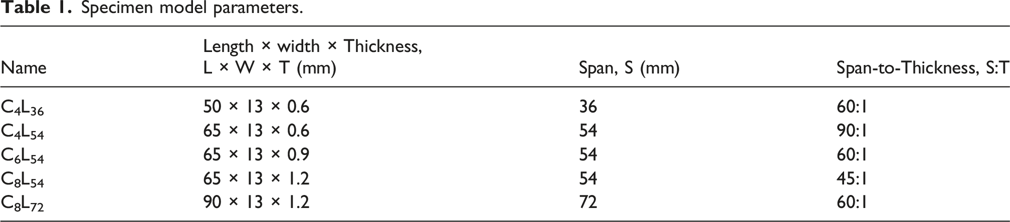
Specimen model parameters.
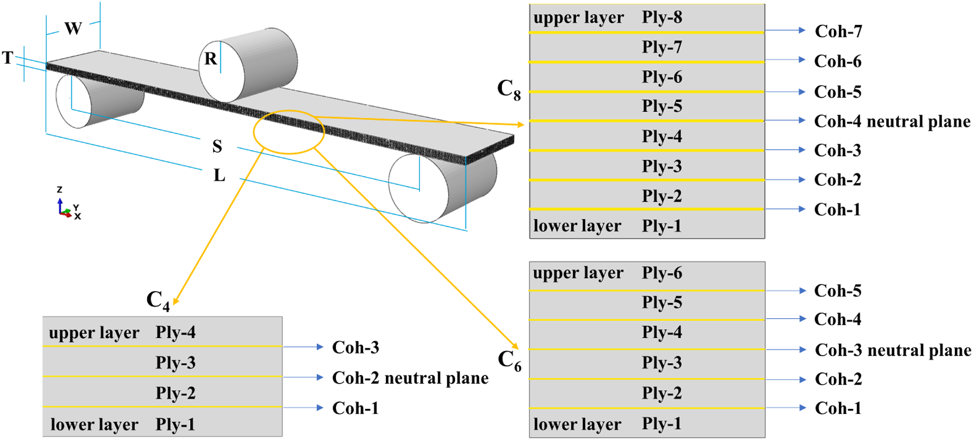
Geometric models of laminates with different stacking thickness under three-point bending.
Damage constitutive of composite laminates
The damage modes of composite laminates are complex, including fiber damage, matrix damage and interface cracking. 37 Therefore, a constitutive model based on in-plane failure and interlaminar failure is introduced in this study. Damage in composite laminates arises from the interplay between interlaminar and in-plane mechanisms. Interlaminar damage, characterized by delamination at ply interfaces, is typically triggered by shear stresses and weak interfacial bonding. In contrast, in-plane damage, such as fiber breakage and matrix cracking within individual plies, is governed by the material’s tensile and compressive strength.
In-plane damage constitutive model
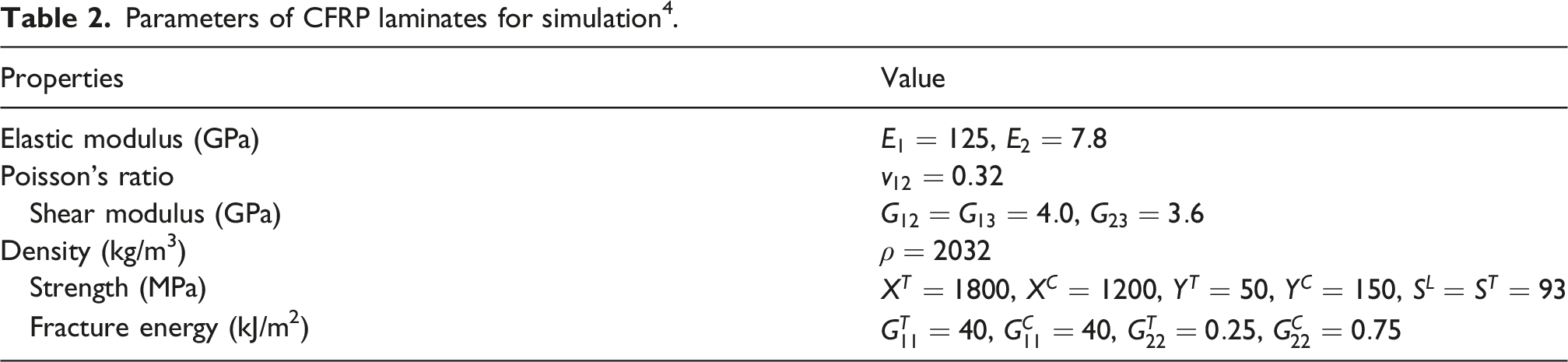
Parameters of CFRP laminates for simulation 4 .
Hashin damage initiation criteria 38 .
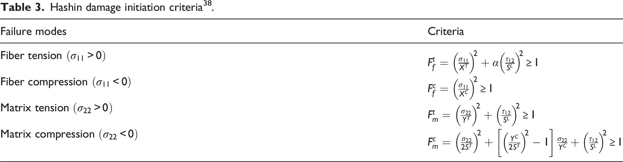
In Table 2 and Table 3, σ11, σ22 and τ12 are the stress tensions, X T , X C represent the tensile and compressive strength in the x-direction, and Y T and Y C represent the tensile and compressive strength in the y-direction. Additionally, S L and S T represent the longitudinal and transverse shear strength. The coefficient α determines the contribution of the shear stress to the fiber tensile initiation criterion.
Before damage occurs, the material behaves linearly elastic. When damage reaches the initiation criterion, the material stiffness degrades, and the damage variable at this time can be expressed as d
i
. Relationship between equivalent stress and equivalent displacement.
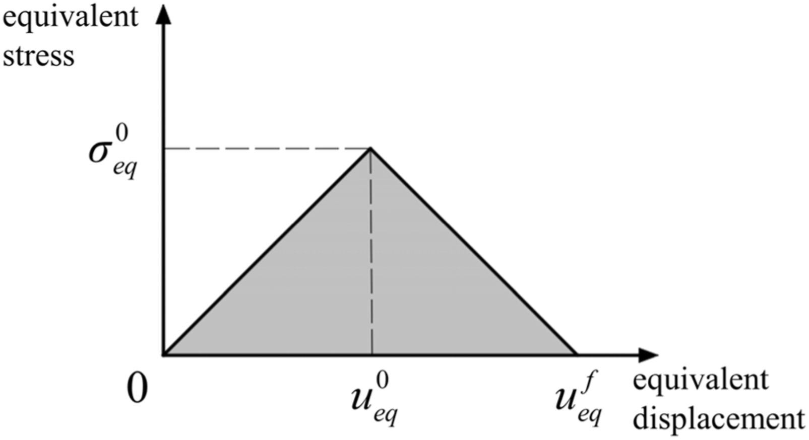
Interlaminar interface damage constitutive model



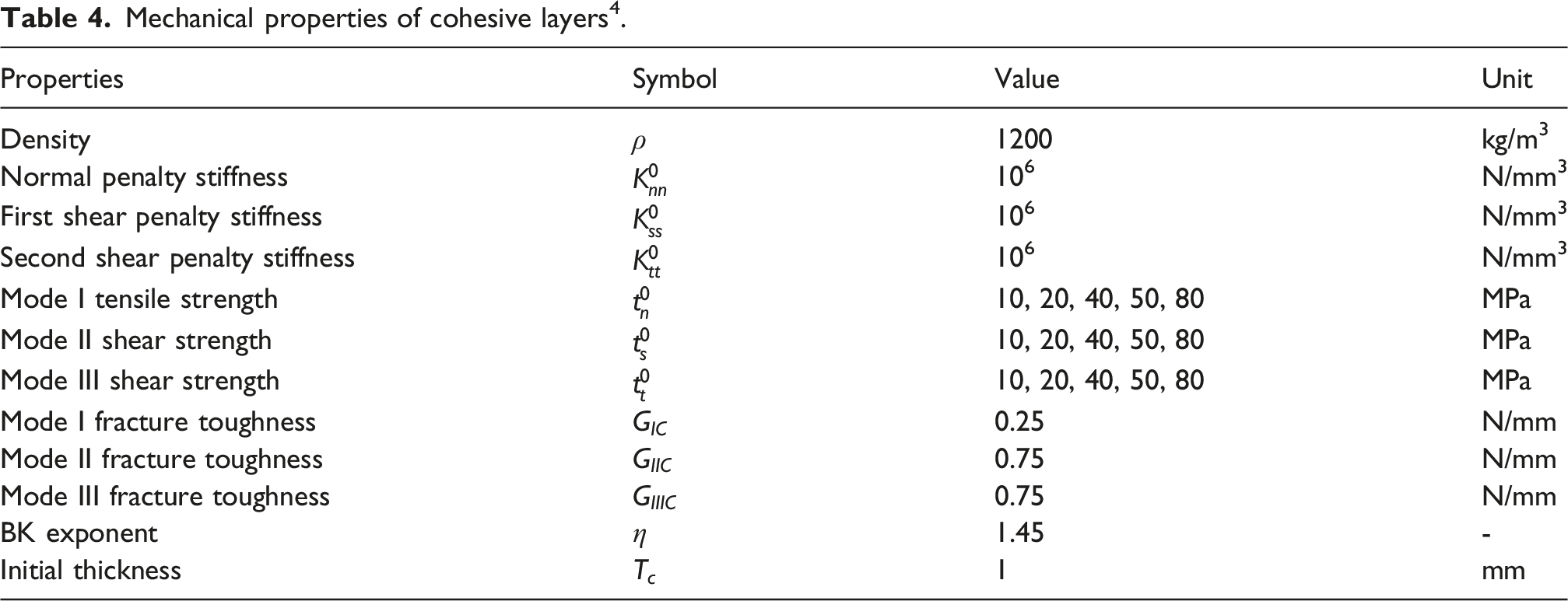
Mechanical properties of cohesive layers 4 .
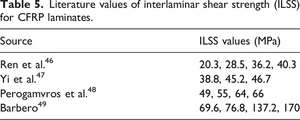
Literature values of interlaminar shear strength (ILSS) for CFRP laminates.
Mesh and boundary condition
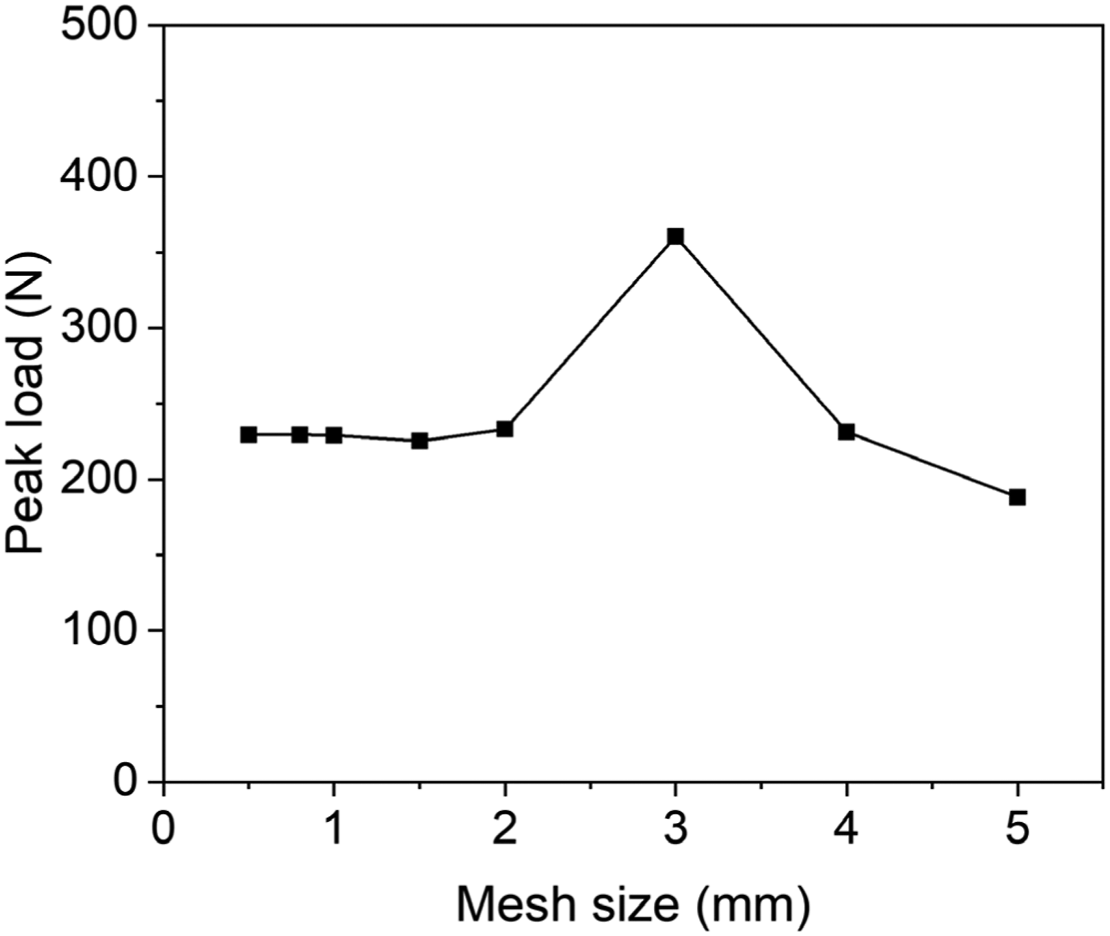
The boundary conditions are as follows. As shown in Figure 3, face1 and its opposite face: U2 = 0; Face2 and its opposite face: U2 = 0, UR1 = 0, UR3 = 0; Supports: U1 = U2 = U3 = UR1 = UR2 = UR3 = 0. The displacement load is applied in the U3 direction. U1, U2 and U3 are the axial displacements in 1, 2 and 3 directions, respectively. UR1, UR2, and UR3 are rotations on the 1, 2, and 3 axes, respectively. The contact properties between the loading nose and the laminate are set as face-to-face contact. The fiber layer utilizes an eight-node continuous shell element (SC8R), and the interlaminar interface employs an 8-node three-dimensional cohesive element (COH3D8) with a thickness of zero. As shown in Figure 4, simulations of the C6 laminate with different mesh sizes indicate that the results stabilize when the mesh size is smaller than 2 mm. The peak load difference between the 0.5 mm and 0.8 mm meshes is less than 1‰. Therefore, balancing computational time and accuracy, a mesh size of 0.5 mm × 0.5 mm is adopted. Finite element mesh and boundary conditions. The variation of the peak load with mesh size for the C6L54 laminate with an ILSS of 50 MPa.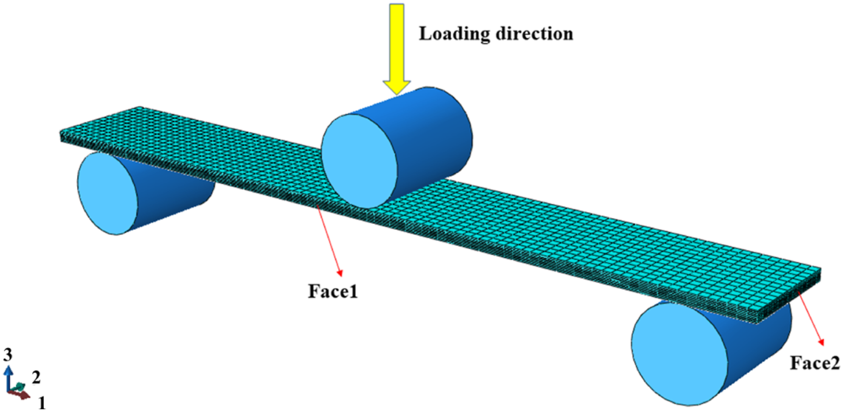
In order to ensure calculation accuracy and prevent non-convergence, an explicit dynamics solver is employed for quasi-static analysis. Mass scaling is not used in the simulations. A smooth step loading function is applied with a total loading time of 1 s. Furthermore, the quasi-static condition is verified by examining the kinetic energy relative to the internal energy. As presented in Figure 5, the kinetic energy constituted only 0.28%, 0.09%, and 0.46% of the internal energy at the peak load for the C4L36, C6L54, and C8L72 laminates, respectively. Such low ratios justify that the kinetic energy is negligible and the analysis accurately represents quasi-static behavior. Changes in internal energy and kinetic energy over time in simulation.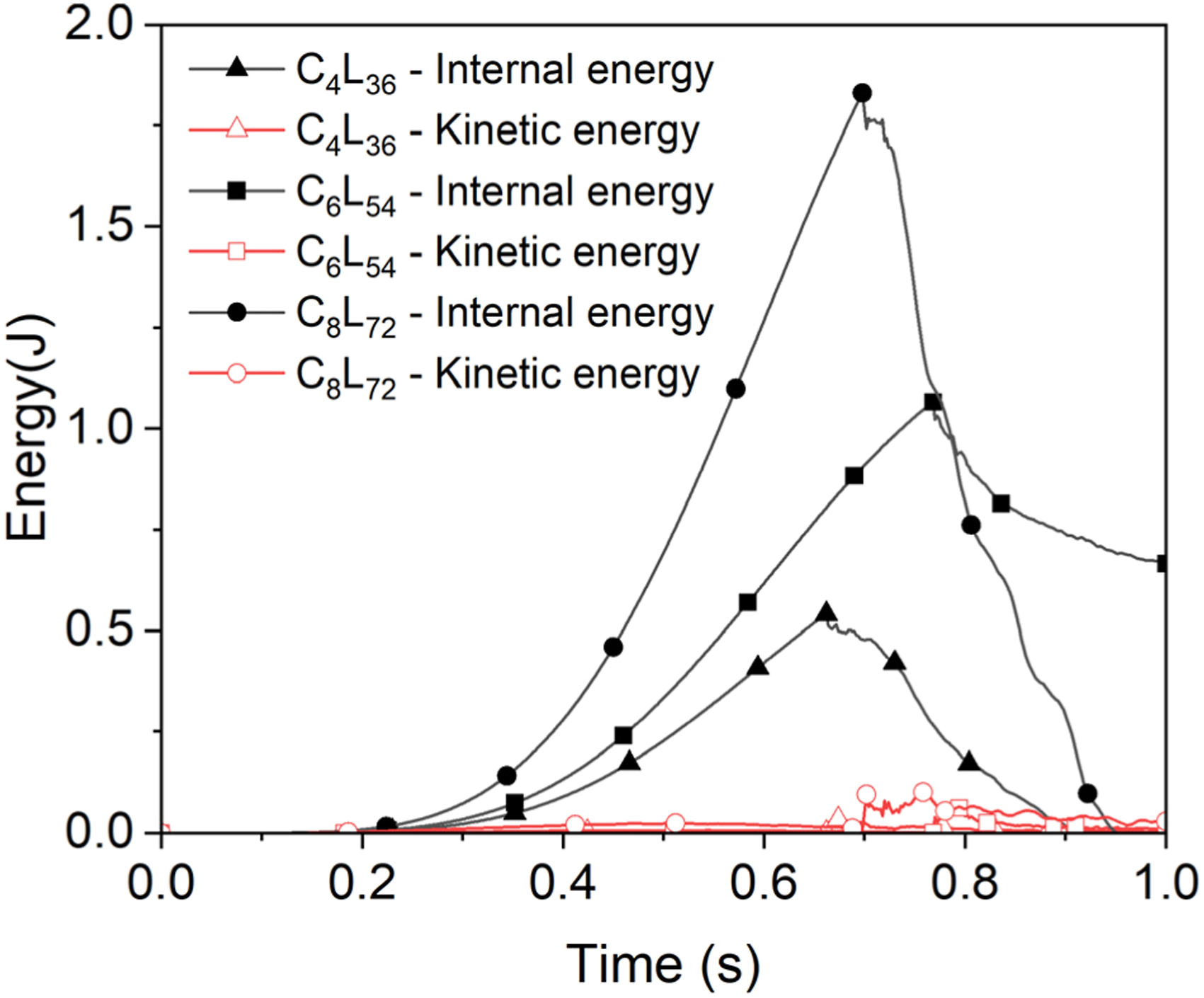
Experiment
Materials and sample preparation
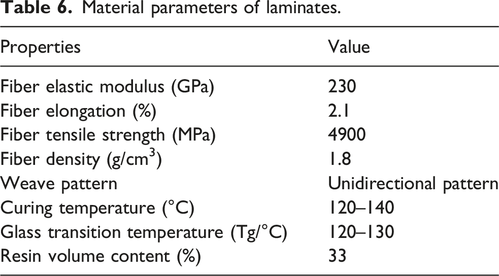
The CFRP unidirectional laminates with three different stacking thicknesses used in this study are manufactured by Dezhou Blue Label Composite Materials Technology Co., Ltd. According to the manufacturer’s description, the laminates are produced using a hot-press consolidation process with wet lay-up techniques. The thickness of a single fiber layer is 0.15 mm. The manufacturing equipment is shown in Figure 6. The material parameters provided by the manufacturer are presented in Table 6. Manufacturing equipment: (a) Autoclave; (b) Cutting machine. Material parameters of laminates.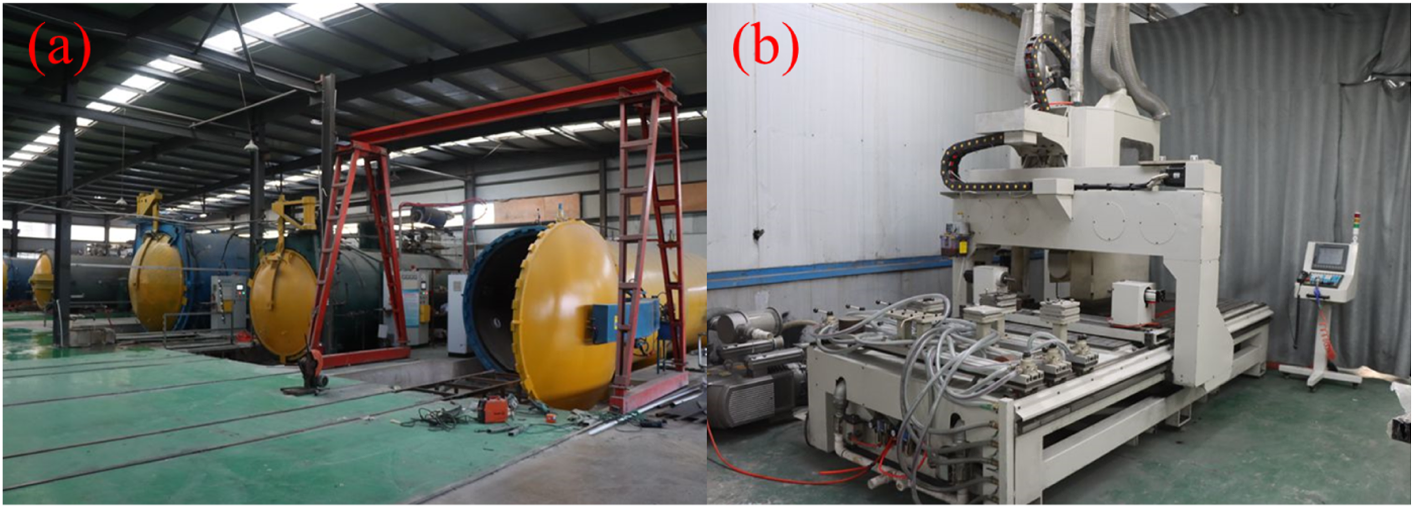
The preparation process involves the following steps: Mixing the resin and hardener evenly, and setting it aside for later use. Placing a layer of T700 carbon fiber cloth in the mold and using a roller to evenly spread the mixed resin on the surface. Repeating the steps of stacking carbon fiber cloth and applying resin until the desired number of layers is achieved. Place the stacked materials in a vacuum box to remove residual air bubbles from the resin. Place the degassed material into an autoclave for solidification at a temperature of 150°C and a pressure of 1.5 MPa. After 10 h, when curing is complete, taking out the CFRP laminate and cutting it.
The fiber volume content of the CFRP laminate prepared in this experiment is 67%. The fiber volume content used in the simulation is 60%. The effect of fiber volume fraction is discussed in Section 4.1. The mechanical properties of the CFRP laminate in the experiment are higher than those given by the simulation data, with a difference value ≤12%. The objective of this study is to investigate the patterns of quasi-static progressive damage evolution, rather than to achieve accurate strength predictions. Therefore, despite this difference, and considering the experimental conditions and simulation convenience, no corrections are made to the simulation data. It’s important to note that this discrepancy does not affect the comparison of various parameters, as the comparison is conducted within the experimental group and the simulation group.
Flexural test
According to ASTM D7264 testing standards,
36
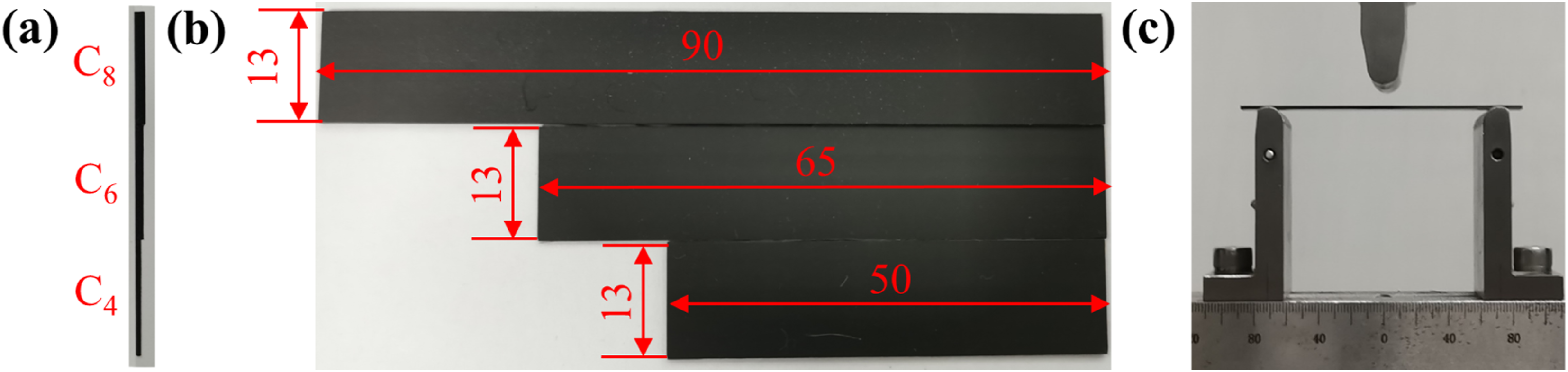
a three-point bending test is conducted. The diameter of the loading nose and supports is 10 mm, and the span-to-thickness ratio (S:T) of all the specimens is 60:1. The quasi-static loading rate is 1 mm/min. The thickness of the prepared laminates is as follows: C4 (0.6 mm), C6 (0.9 mm), and C8 (1.2 mm), as shown in Figure 7. Each group tested 4 samples and the flexural strength is calculated as follows: (a) Side view of the specimens; (b) Top view of the specimens; (c) Test equipment.
Results and discussion
Load-displacement curves and damage evolution
Firstly, a comparison is made between the simulated and experimental load-displacement curves under three different stacking thicknesses using the constant span-to-thickness ratio models (C4L36, C6L54, C8L72) that follow ASTM D7264. The additional constant span models (C4L54, C6L54, C8L54) are then used to isolate the pure thickness effect, as discussed in Section 4.4. Subsequently, numerical simulations are conducted to analyze the damage evolution process of C4L36 laminate. The notations in Figure 8 are defined as follows: fiber tensile initiation criterion (FT), fiber compression initiation criterion (FC), and interlaminar interface damage (SDEG). Their values range from 0 to 1. Figure 8(a) illustrates the simulated load-displacement curves of the laminates. It is evident that with increasing stacking thickness, the peak load and fracture displacement of the laminate also increase. Figure 8(b)-(d) present a comparison of the simulation and experimental load-displacement curves of C4L36, C6L54, and C8L72 laminates. The simulation and experiment curves exhibit a good fit. It is noteworthy that the peak load and fracture displacement of the simulation curves are smaller than those of the experiment. This discrepancy may be attributed to the inconsistency in fiber volume content between the simulation and the experimental setup, as mentioned in section 3.1. The fiber volume content is 67% in the experiment and 60% in the simulation. According to the rule of mixtures formula, the relationships between the longitudinal modulus E1, the longitudinal strength σ1, and the fiber volume fraction V
f
can be obtained as follows
49
: (a) Simulated load-displacement curves of the laminates; (b) Comparison of simulation and experimental load-displacement curves for C4L36 laminate; (c) Comparison of simulation and experimental load-displacement curves for C6L54 laminate; (d) Comparison of simulation and experimental load-displacement curves for C8L72 laminate; (e) Damage evolution cloud diagram of C4L36 laminate with ILSS of 50 MPa. Effect of fiber volume fraction on simulated peak load with ILSS of 50 MPa.

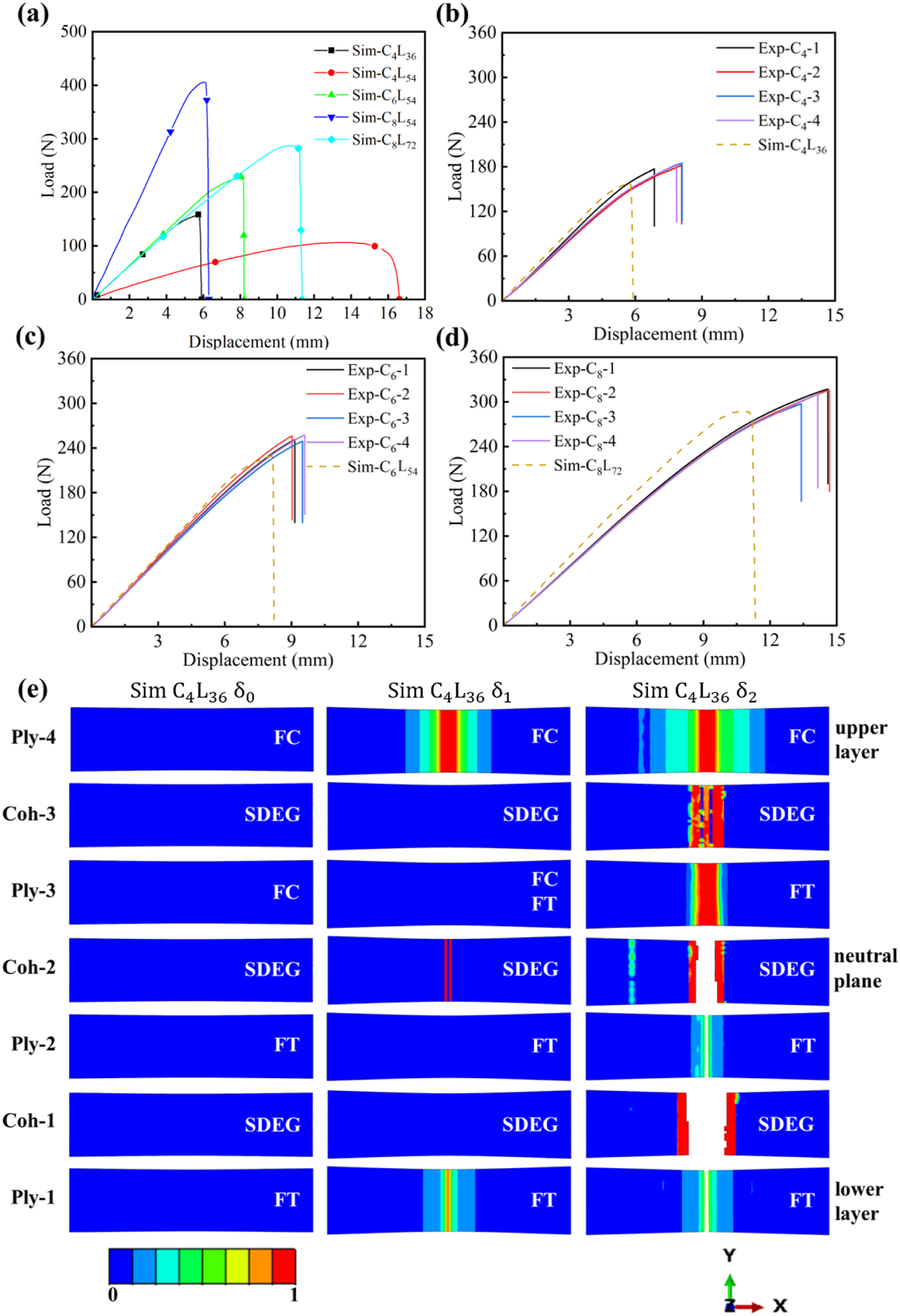
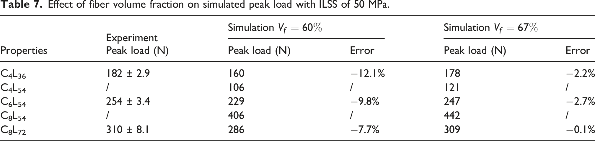
Figure 8(e) illustrates the damage initiation and evolution process of each layer (Ply) and interface (Coh) of the C4L36 laminate under simulation conditions with an interlaminar shear strength (ILSS) of 50 MPa. The C6L54 and C8L72 laminate exhibit similar phenomena; hence, the damage initiation and evolution process of only C4L36 is presented. δ0, δ1, and δ2 represent different displacement loadings, corresponding to Figure 8(a). When the displacement is loaded to δ1, damage initiation is relatively large below the loading nose of the upper and lower layers (Ply-4, Ply-1), and damage occurs at the neutral plane Coh-2. After reaching displacement δ2, fiber layers Ply-1 and Ply-2 below the neutral plane are fractured, resulting in interface Coh-1 cracking, and the damage evolution of interface Coh-1 is rapid. This may be attributed to the higher ILSS, which could lead to a less distinctive evolution process of interface damage. Therefore, the subsequent analysis in the following sections assesses the impact of ILSS on laminate damage evolution.
Influence of ILSS on damage and failure
Differences in interface strength can influence the fracture mode. Therefore, numerical simulations are employed to conduct a parametric analysis of the ILSS. In the cohesive zone model,
Figure 9 illustrates the load-displacement curves of the C4L36 laminate under five different ILSS values. The curves demonstrate that as the ILSS increases from 10 MPa to 40 MPa, both fracture displacement and peak load increase. However, the fracture displacement and peak load remain essentially unchanged as the ILSS increases from 40 MPa to 80 MPa. Key positions are marked: δ0 represents a specific moment in the rising section of the curve before the peak load, δ1 represents the peak load of each curve, δ2 represents the fracture, δ1.4 and δ1.7 represent two displacement loading moments between δ1 and δ2 in ILSS80. Load-displacement curves under different interlaminar shear strengths (ILSS).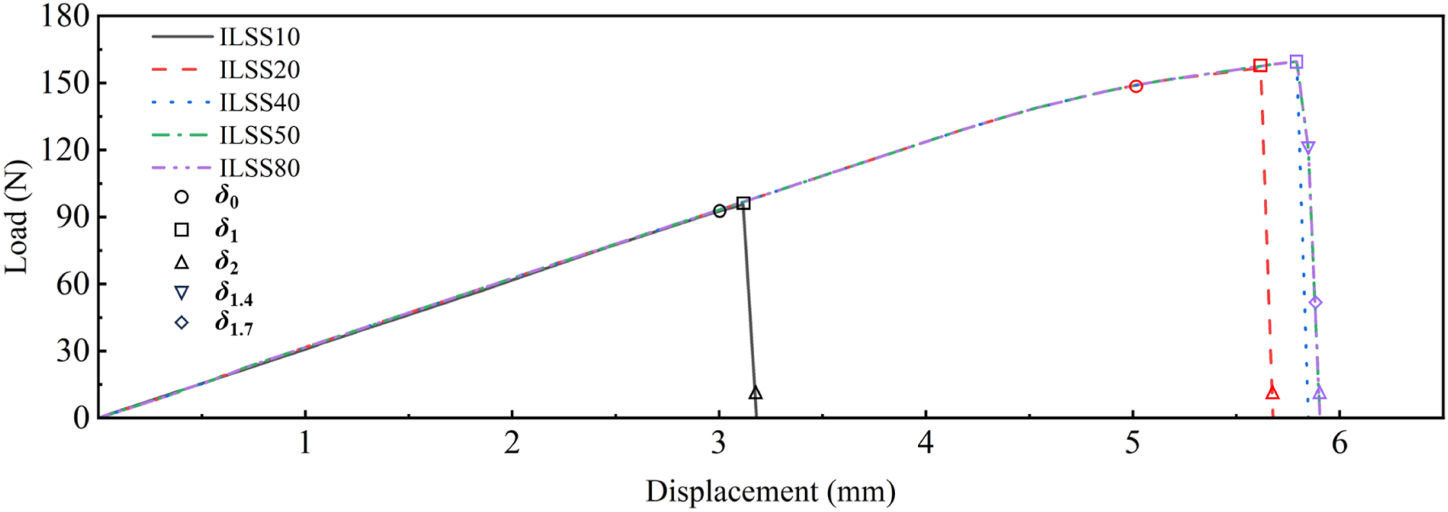
According to Figure 10, it is observed that the Mises stress at the neutral plane (Coh-2) is the highest among all interfaces. The figure only provides Mises stress under ILSS10/20 MPa, but the stress distribution under ILSS40/50/80 MPa is generally consistent with that under ILSS20 MPa. From this, it can be inferred that the neutral plane is prone to damage. Interlaminar interface Mises stress: ILSS10/20 MPa.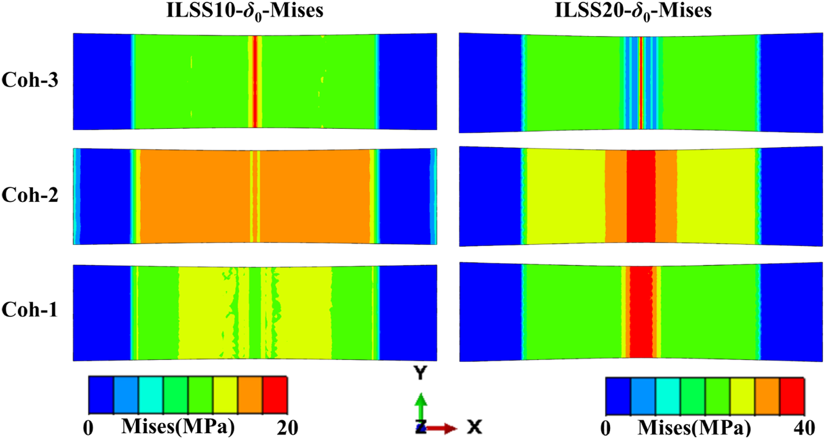
Delamination is a typical failure mode of composite laminates. High interlaminar shear forces or low ILSS can lead to delamination, resulting in the material losing its load-bearing capacity.
50
Figure 11(a) illustrates the damage evolution process under ILSS10 MPa. At the moment δ0, Coh-2 is damaged first. As the displacement progresses to δ1, Coh-1 and Coh-3 also experience damage, but due to the greater extent of damage in Coh-2, it leads to the failure of Coh-2 at δ2. At this point, Ply-1 and Ply-4 have not reached damage initiation. Therefore, the simulation suggests that the laminate experiences delamination failure under this condition. Additionally, observing Figure 9, the slope of the rising section of the ILSS10 curve does not change, and no stiffness attenuation occurs. This is because the Ply-4 fiber layer has not been damaged, which means that the part where the loading nose contacts the upper surface layer remains intact. Damage evolution cloud diagram and fracture morphology of C4L36 laminate: (a) ILSS10 MPa; (b) ILSS20 MPa; (c) ILSS40 MPa; (d) ILSS80 MPa; (e) Fracture morphology under different ILSS.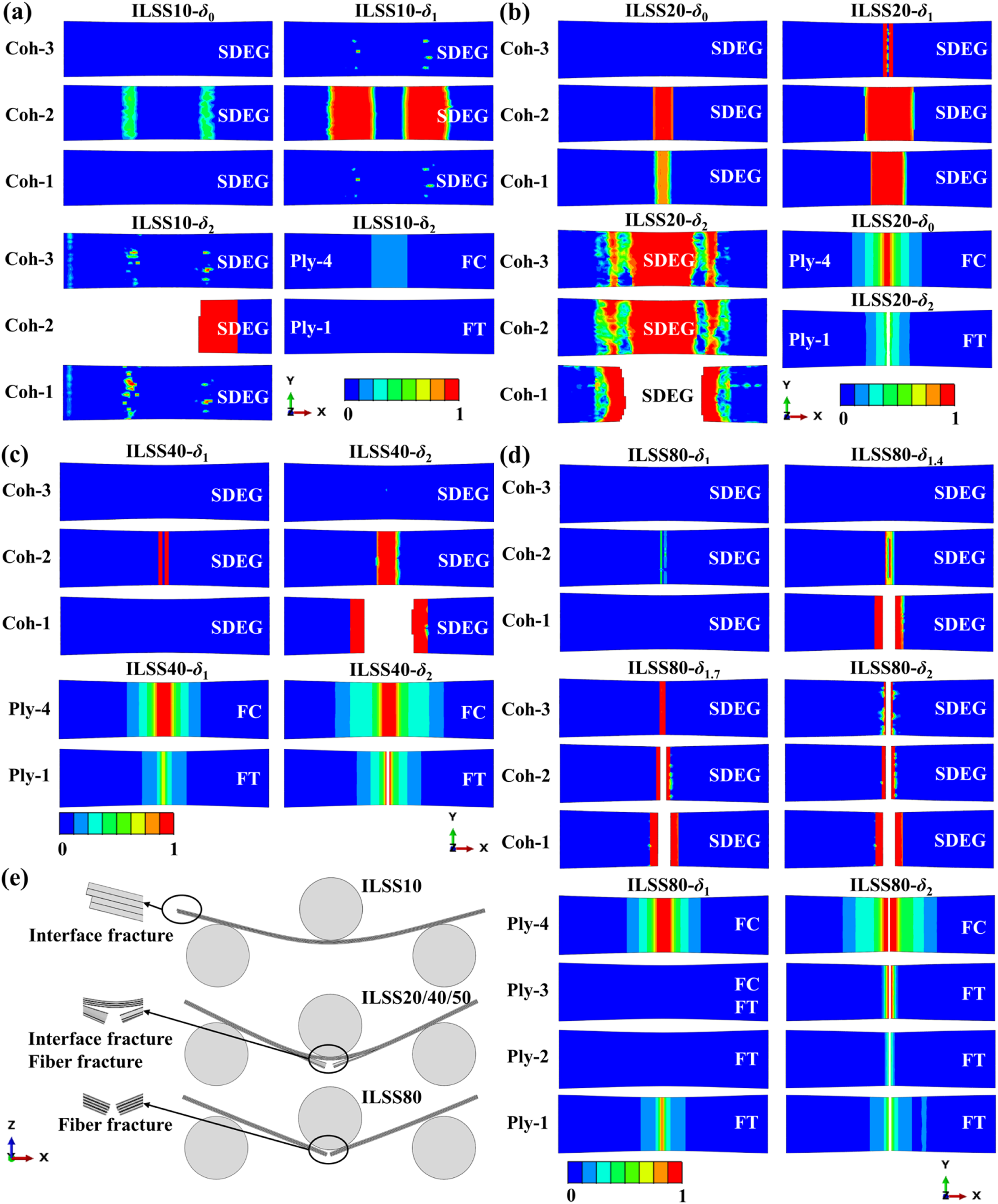
In Figure 11(b), the ILSS is increased to 20 MPa. It is observed that although Coh-2 experiences the most damage at moments δ0 and δ1, Coh-1 cracks first at moment δ2. This is because at moment δ2, the fibers in Ply-1 fracture, leading to interface cracking. Additionally, the location of interface damage under ILSS20 MPa is different compared to that under ILSS10 MPa. The damage location of each layer interface under ILSS10 MPa is in the middle area between the loading nose and the support, while the damage location under ILSS20 MPa is directly below the loading nose. Observing Figure 10, the maximum stress distribution under ILSS10 MPa is mainly between the loading nose and the support, while under ILSS20 MPa, it is more concentrated under the loading nose. Additionally, combining with Figure 9, it is evident that under ILSS20 MPa, there is stiffness degradation in the peak load region of the curve. This is attributed to the compression damage (FC) initiation criterion in the fibers of Ply-4 reaching 1 at moment δ0.
In Figure 11(c)-(d), it is observed that when the ILSS rises to 40 MPa or 80 MPa, it becomes challenging to detect the failure of the interface, and only minor damage occurs when the displacement is loaded before the peak load. Beyond ILSS40 MPa, the peak load and fracture displacement no longer increase, as at this point, the factor controlling the material strength becomes the strength of the fiber layer.
Figure 11(e) illustrates the final fracture morphology of the laminate under different ILSS. The failure mode of ILSS10 MPa laminates is interface delamination cracking, ILSS20 and 40 MPa result in interface cracking when fiber fracture occurs, and ILSS80 MPa primarily exhibits fiber fracture. Consequently, the simulation results suggest that when the interface strength is weak, the fracture mode of the laminate tends to be delamination failure. Conversely, if the interface strength is high, the laminate is more susceptible to fiber fracture.
Figure 12 presents a comparison between the simulation and experimental failure modes of C4L36 laminates. The experimental laminates predominantly exhibit fiber fracture, which is qualitatively consistent with the simulation result of ILSS80. This suggests good interlaminar bonding quality, although direct ILSS measurement is not performed. Comparison of simulation and experimental fracture morphology of C4L36 laminates.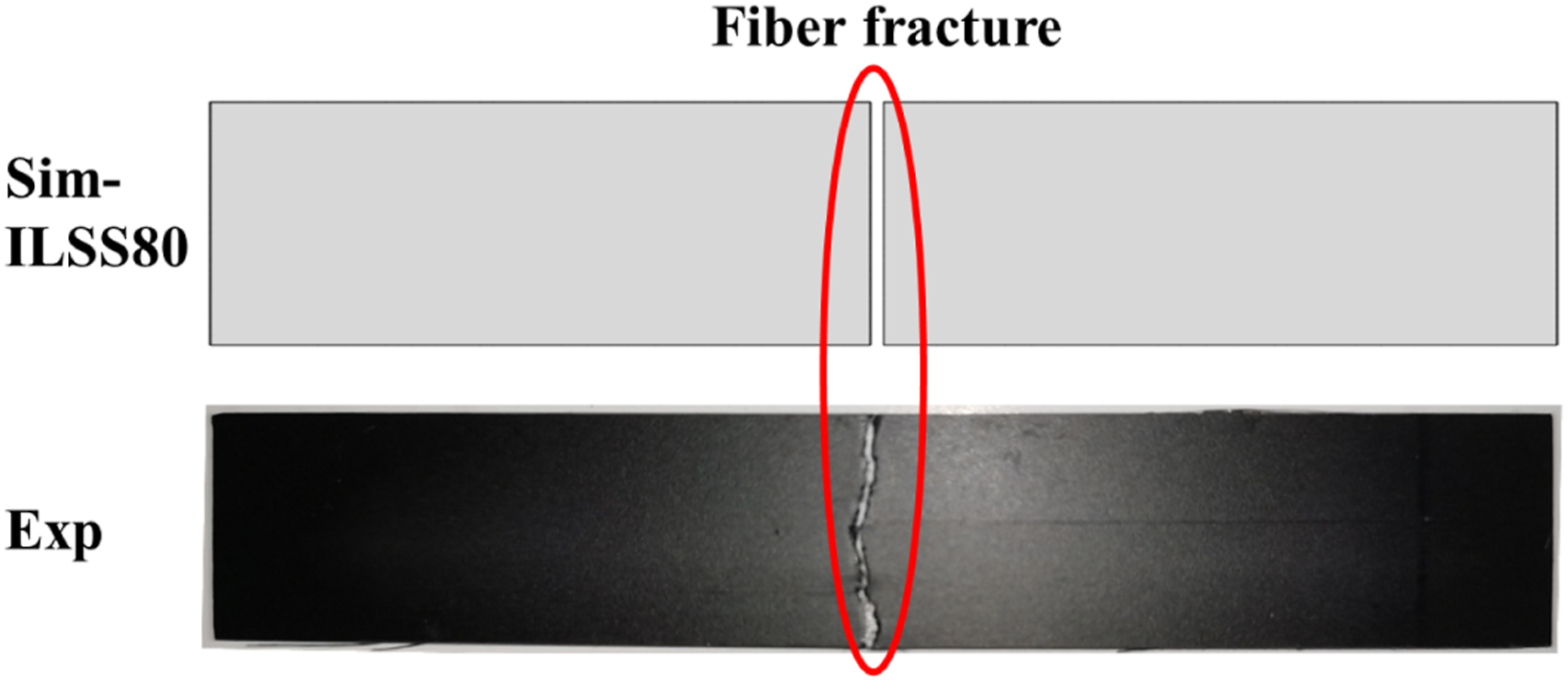
Under higher ILSS conditions (40–80 MPa), the interface damage rate is extremely fast, making it difficult to capture the progressive damage process numerically. Therefore, an ILSS of 20 MPa is selected for the parametric study, as the relatively slower damage rate allows for clearer observation and quantitative characterization. To further investigate the influence of stacking thickness on interface damage, three different stacking thicknesses are established by FEA, namely, C4L36, C6L54, and C8L72, under ILSS20 MPa. The following analysis and conclusions are specific to this ILSS condition.
Interlaminar interface catastrophic failure model
The failure mode of CFRP laminates is typically considered as brittle fracture, and the damage occurring at the interface of each layer can be seen as catastrophic failure. Therefore, a catastrophic damage model is employed to explore the damage evolution rules of the interface of laminates under different stacking thickness.51,52 The purpose of the “interlaminar interface catastrophic failure model” is to analyze and predict the damage evolution and failure behavior of the interlaminar interface in CFRP laminates under bending loads. By characterizing the brittle fracture mechanism, the model identifies the power-law relationship governing damage progression and its rapid increase near the fracture point. It aids in understanding the sensitivity of damage rate to displacement, providing insights for optimizing laminate design to enhance mechanical performance and durability under varying stacking thicknesses and interlaminar shear strengths.
Damage definition
The initial damage N0 is defined as the number of elements with an interface damage degree SDEG exceeding a given threshold at the point of deviation from linearity during the loading process, and the complete damage N
f
is defined as the number of elements with an interface damage degree SDEG exceeding the threshold at the peak load. To examine the sensitivity of the damage statistics to the threshold selection, three SDEG values (0.6, 0.7, and 0.8) are analyzed and compared. The results for the SDEG threshold of 0.7 are shown in Figure 13(a). The initial damage variable is represented by (a) Damage evolution cloud diagram at the neutral plane of laminates under different stacking thickness; (b) Relationship between normalized damage rate and displacement; (c) Relationship between damage rate and normalized displacement; (d) Logarithmic relationship between damage rate and displacement.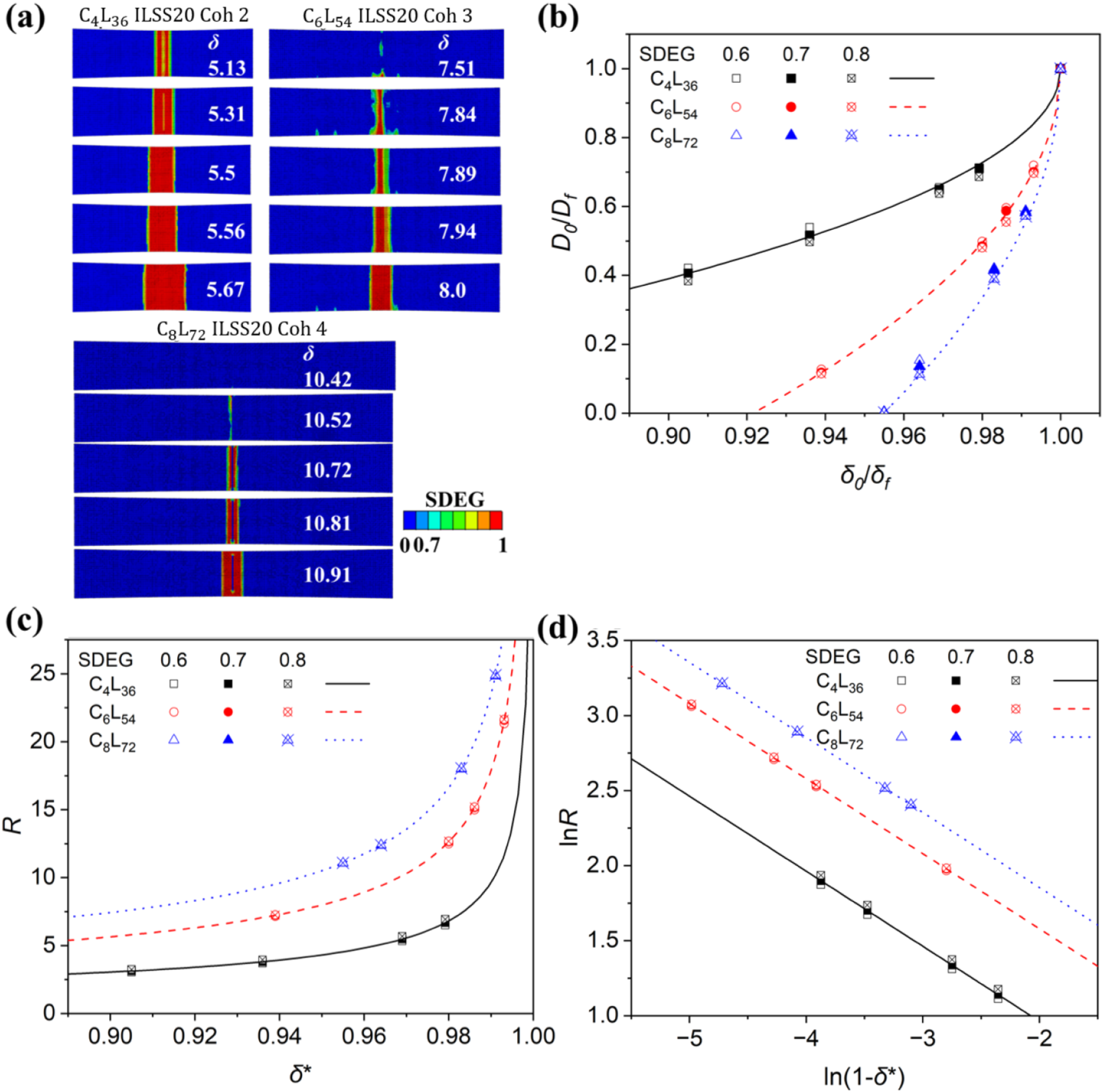
The normalized damage variable
Damage model: If the control variable of a system, such as the laminate displacement δ, is continuous and differentiable before catastrophic rupture, then damage D can be expanded using Taylor’s formula as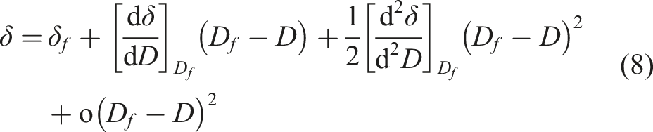

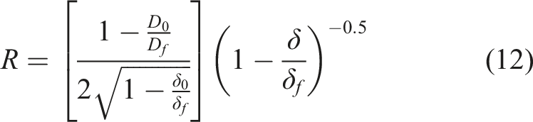
In addition, the interface damage rate of the laminates can be obtained from equation (9).
Equation (10) shows that when δ approaches δ f , the damage rate R increases sharply.
Comparison of simulation results and damage model
Equation (11) is derived from equation (9). It can be seen from Figure 13(b) that the simulation results (symbols) agree with the theoretical power-law function curve of equation (11). It can be observed that although the initial damage points of each stacking thickness are different and the dispersion is large, the dispersion of all damage points becomes smaller when the interface tends to be completely damaged, and the damage model is more effective. For catastrophic damage, it is difficult to obtain the failure point near the fracture displacement. Therefore, by collecting partial failure points using this model, it is possible to infer the damage failure pattern.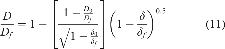
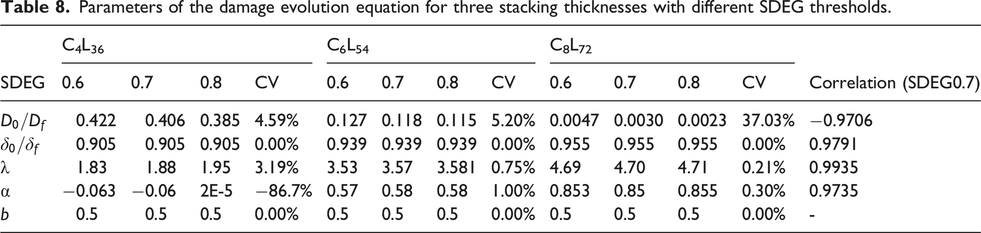
Parameters of the damage evolution equation for three stacking thicknesses with different SDEG thresholds.
Simulated and experimental flexural properties.
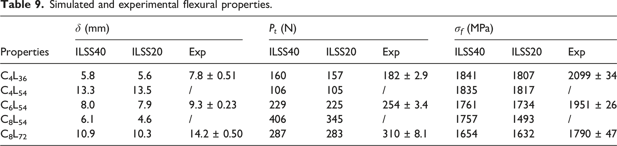
Figure 13(d) shows the logarithmic relationship between the simulation results and the damage model. The figure suggests that the interface damage rate follows a power-law singularity of −0.5 as indicated by the model, for various stacking thicknesses.
Influence of stacking thickness and ILSS on flexural properties
Understanding the influence of stacking laminate thickness and ILSS on flexural properties contributes to the design of composite materials. Based on the simulation results, when ILSS is increased to 40 MPa, the load-displacement curve of the material remains unchanged. Therefore, ILSS20 and ILSS40 are selected for analysis. Table 9 presents the average mechanical properties of each specimen under simulation and experimental conditions, where “Exp” represents “experimental.”
In combination with Figure 14(a), for the constant span-to-thickness ratio group (C4L36, C6L54, C8L72), which follows ASTM D7264 for simulation-experiment validation, the fracture displacement and peak load increase with stacking thickness. Changing ILSS from 20 MPa to 40 MPa leads to limited improvements in peak load (1.4–1.9%) and fracture displacement (1.3–5.8%). As depicted in Figure 14(b), the flexural strength decreases with increasing stacking thickness. To statistically validate this trend, a one-way analysis of variance (ANOVA) is conducted on the experimental flexural strength across the three thicknesses (C4L36, C6L54, C8L72). The results show a significant effect of stacking thickness on flexural strength (F (2,9) = 3735, p < .001), confirming that the decrease is statistically significant. Curves of different stacking thickness and ILSS: (a) Load-displacement curves; (b) Flexural strength-stacking thickness curves.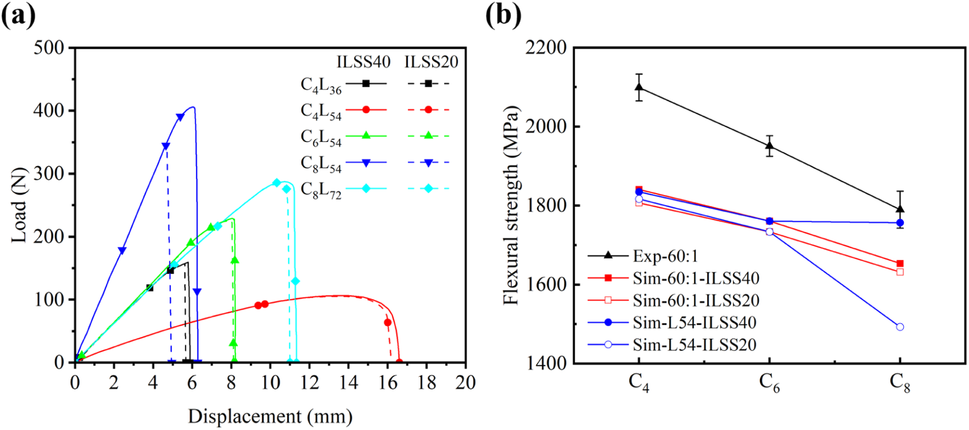
To isolate the pure thickness effect from structural scale effects, the constant span group (C4L54, C6L54, C8L54, span fixed at 54 mm) is examined. In this group, as stacking thickness increases from 0.6 mm to 1.2 mm, the peak load increases from 106 N (C4L54) to 406 N (C8L54) at ILSS40, while the flexural strength decreases from 1835 MPa to 1757 MPa (see Table 9), consistent with the trend observed in the constant span-to-thickness ratio group. This confirms that the thickness-dominated reduction in flexural strength is not an artifact of changing span length.
Combining Figure 15(a)-(b), it can be observed that with increasing stacking thickness, compression damage to the upper layer material gradually increases, leading to a decrease in the overall flexural strength. According to the weakest-link theory of Weibull,
53
a thicker specimen has a higher probability of encountering the weakest link during failure, resulting in lower overall strength. This phenomenon is consistent with Qiu et al.’s
54
study on the mechanical properties of nacre in Hyriopsis cumingii. In addition, increasing ILSS can also enhance flexural strength, though the effect is relatively small within the studied range. (a) Fiber compression damage cloud diagram on the upper layer before fracture; (b) Fracture morphology in the experiment.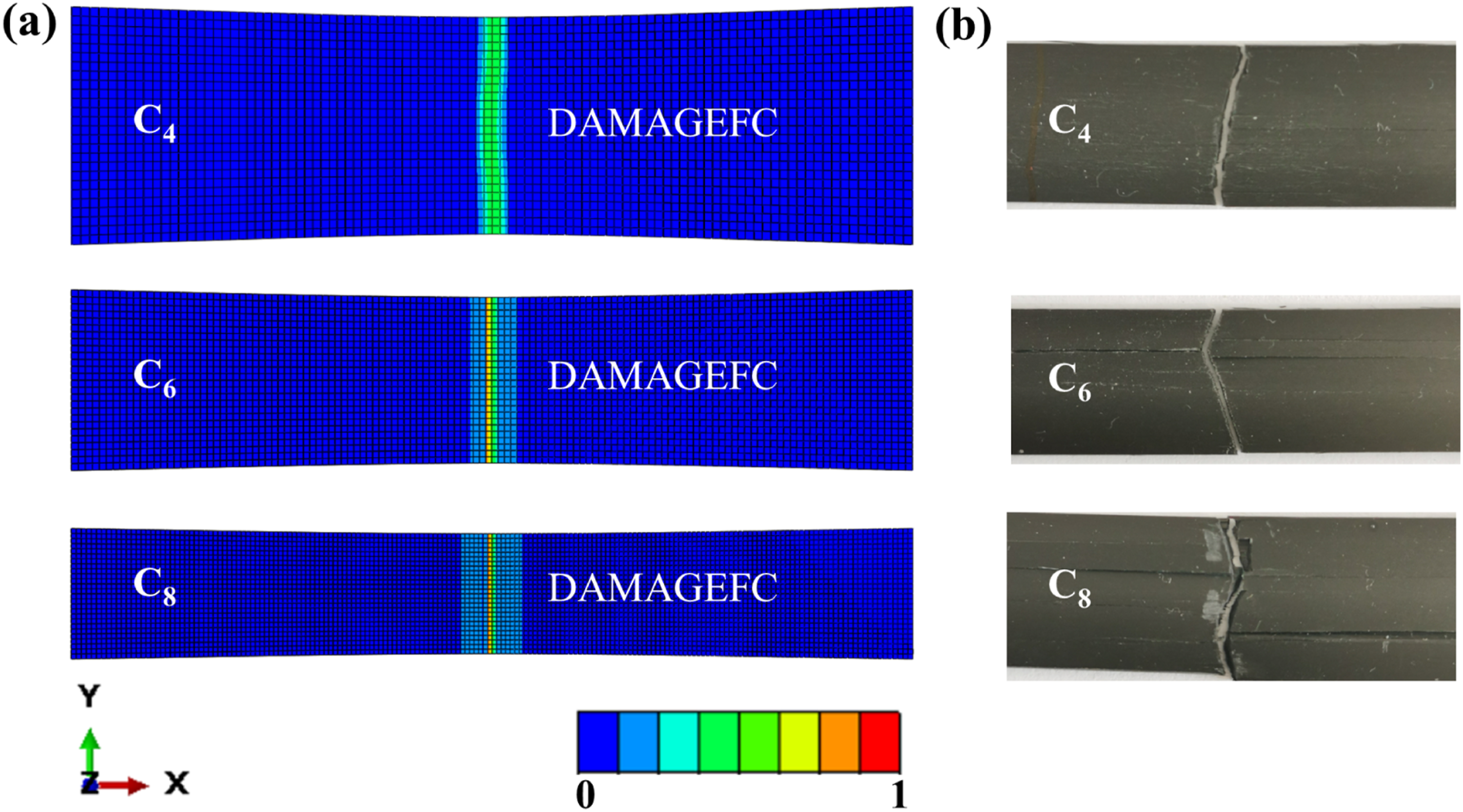
Upon comparing simulation results with experimental data (C4L36, C6L54, C8L72), the overall trends are consistent. Although some discrepancies exist, they do not significantly affect the representation of the material’s overall performance. As discussed in Section 4.1, these discrepancies are primarily attributed to the difference in fiber volume fraction between simulation (V f = 60%) and experiment (V f = 67%).
Conclusion
In this study, the three-point bending damage evolution process of unidirectional carbon fiber reinforced polymer (CFRP) laminates is characterized through finite element analysis, experiment, and a catastrophic failure model. The effects of stacking thickness and interlaminar shear strength (ILSS) on the damage evolution and flexural properties of unidirectional CFRP laminates are investigated. The key findings of this research can be summarized as follows: (1) As the stacking thickness increases (0.6 mm–1.2 mm), the experimental flexural strength decreases from 2099 MPa to 1790 MPa (see Table 9). The compressive stress on the upper layers increases, leading to more compression damage to the fibers and thereby causing a decrease in the flexural strength of the unidirectional CFRP laminates. Simulations with constant span length confirm that this thickness-induced trend is not caused by concurrent changes in span length. (2) Simulation results indicate that for laminates with high ILSS (20, 40, 50, and 80 MPa), the predominant failure mode is fiber fracture. In contrast, laminates with low ILSS (10 MPa) primarily exhibit delamination failure and their neutral plane is most susceptible to damage (see Figure 11). (3) At ILSS20 MPa, the catastrophic failure model reveals that the damage and failure of the interlaminar interface of unidirectional CFRP laminates obey power-law characteristics with a power index of 0.5 (see equation (11) and Table 8), indicative of brittle fracture behavior. As the displacement approaches the fracture point, damage becomes complete, and the damage rate increases dramatically without bound. The damage coefficient λ increases from 1.88 for C4L36 to 4.70 for C8L72 (see Table 8), indicating that under this specific interlaminar strength condition, thicker stacking thickness leads to faster damage progression, with initial damage points closer to the fracture point. This finding is drawn from ILSS20 MPa, where the slower damage rate enables numerical tracking; at higher ILSS levels (e.g., 80 MPa), the damage evolves too rapidly for such quantitative comparison.
The insights gained from this paper provide useful guidance for optimizing the design of carbon fiber structural components, enhancing their safety, and ensuring stability in practical engineering applications. While this study focuses on unidirectional CFRP laminates, further investigation for multidirectional or quasi-isotropic laminates is already underway. In addition, it should be noted that the conclusions regarding damage evolution mechanisms are predominantly simulation-based and should be interpreted as such. Direct experimental measurement (e.g., in situ observation of damage progression, short-beam shear testing for ILSS) is therefore recommended for future work.
Footnotes

Author contributions
Chengyu Guan: Conceptualization, Methodology, Software, Writing - Review & Editing, Funding acquisition.
Huanyu Li: Conceptualization, Methodology, Software, Investigation, Writing - Original Draft.
Shuai Wang: Writing - Review & Editing, Funding acquisition.
Lihong Liang: Supervision, Writing - Review & Editing, Funding acquisition.
Funding
The authors disclosed receipt of the following financial support for the research, authorship, and/or publication of this article: This work is supported by the National Natural Science Foundation of China through Grants #91860102, #12402149, #12172035, #92160203, the Fundamental Research Funds for the Central Universities of China (buctrc201930, BH202422), and Postdoctoral Fellowship Program of CPSF (GZC20230204).
Declaration of conflicting interests
The authors declared no potential conflicts of interest with respect to the research, authorship, and/or publication of this article
Data Availability Statement
Data will be made available on request.