
Abstract
Waste management in Greece relies heavily on unsustainable waste practices (mainly landfills and in certain cases uncontrolled dumping of untreated waste). Even though major improvements have been achieved in the recycling of municipal solid waste during recent years, there are some barriers that hinder the achievement of high recycling rates. Source separation of municipal solid waste has been recognised as a promising solution to produce high-quality recycled materials that can be easily directed to secondary materials markets. This article presents an innovative miniature waste separator/compressor that has been designed and developed for the source separation of municipal solid waste at a household level. The design of the system is in line with the Waste Framework Directive (2008/98/EC), since it allows for the separate collection (and compression) of municipal solid waste, namely: plastic (polyethylene terephthalate and high-density polyethylene), paper (cardboard and Tetrapak) and metal (aluminium and tin cans). It has been designed through the use of suitable software tools (LS-DYNA, INVENTROR and COMSOL). The results from the simulations, as well as the whole design process and philosophy, are discussed in this article.
Keywords
Introduction
Waste management in Greece relies heavily on unsustainable waste practices (landfills and to some extent uncontrolled dumping of untreated waste). According to data from May 2013, 73 illegal landfills remain active and 366 inactive illegal landfills need rehabilitation. Even though significant improvement has been achieved in the recycling of packaging waste during recent years, there are still barriers that hinder the achievement of higher recycling rates. The collection coverage for municipal solid waste (MSW) is 100%. According to the latest data available (2011), the composition of MSW is as illustrated in Figure 1.
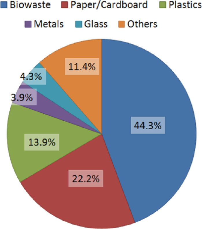
Compositional analysis of MSW in Greece (2011 data) (Hellenic Republic, 2013).
The recycling sector was established in December 2001 and was steadily developed since then, with a decrease after the economic recession (BiPRO, 2013). In Greece, recyclable packaging waste is jointly collected together, as a single (mixed) stream by the Greek ‘Green Dot’ system (HE.R.R.CO). HE.R.R.CO has developed in collaboration with local authorities, a wide network of bins for separate collection of recyclables from other MSW streams. In 2011, the scheme of HE.R.R.Co was extended to certain islands (22 islands in total) (BiPRO, 2013). The collected recyclables are transferred to central separation facilities (material recovery facilities (MRFs)) for their separation. Today, 28 MRFs are in operation in Greece.
Shortcomings of the Greek recycling sector
According to Article 11(1) of the Waste Framework Directive, by 2015 separate collection shall be set up for at least the following: paper, metal, plastic and glass (European Parliament, 2008). The current ‘Green Dot’ scheme has not foreseen such source separation operations for the recyclable part of MSW yet. What is more, a decrease in the amount of the recyclable waste collected has been observed since 2010. This is partially attributed to the economic crisis, as consumers consume less than before, but also to the removal of valuable materials from the bins. More particularly, a large number of economic immigrants remove the most valuable materials from the bins and leave the low value recyclables (BiPRO, 2013). Finally, the recyclables are characterised by low density, resulting in increased transportation needs and costs.
This article presents an innovative miniature waste compressor that can address the shortcomings of the Greek recycling sector, especially for areas where high transportation costs predominate, such as islands and remote areas. The high innovation character of this technology lies in the fact that it comprises a household device that enables the source separation and compression of recyclables, namely plastic, metal and paper. Since the process involves compression of the recyclable items, glass is not considered. To the best knowledge of the authors, no such system exists at a global level. A similar system has been developed by Bigbelly in 2003. This system allows separate collection and compression of municipal waste streams. However, this technology is applied at a district level within a Municipality and not at a household level. To this end, the compressor applied in the Bigbelly system is larger than the one presented in this article and, thus, it cannot satisfy the practical requirements of a typical household.
The miniature recycling unit presented in this article was designed and constructed by the working team of the Unit of Environmental Science and Technology of the School of Chemical Engineering at the National Technical University of Athens, in the framework of the Recycling@Home project (LIFE11 ENV/GR/000950). The laboratory of Manufacturing Technology, which belongs to the School of Mechanical Engineering, assisted in the simulation of the recyclable material compression process. The methodology and the design – along with the simulations for the optimisation of the system and the process involved – are discussed in the following sections.
Methods
The methodology that was followed for the design of the miniature waste separator/compressor comprises the following stages.
Determination of design parameters and specifications.
Determination of main components.
Selection of the household waste to be separately collected and treated.
Simulation of the compression of household waste.
Preliminary design of the unit.
Stress analysis and optimisation.
Final design and production of engineering drawings.
The aforementioned stages of the design process are discussed next.
Design of the home recycling unit
During the first stages of the design procedure the main components of the system were determined. For the selection of the components the following criteria were used.
Construction simplicity
The design of the system does not involve complex geometries. The size and shape of the system must be selected so that the manufacturer can easily construct the device, using simple and cost-effective materials.
User-friendly operation
The system will be operated through a control device that will be able to regulate the pressure and thus the compression ratio per waste stream. The operator will use different buttons for applying different pressure to the sorted waste streams.
Durability and materials
The materials that will be used comprise mainly stainless steel. The main purpose is to ensure durability and enhanced aesthetic appearance at the same time.
Minimum energy consumption
The optimum compression ratio per waste stream must be determined for minimising the energy requirements of the recycling system. This was performed through the use of a software tool (LS-DYNA). The target is to limit the energy requirements at low levels, that is much less than 1 kWh, on a daily basis.
Compression ratio
Target > 3:1.
Practicality
The size and shape of the system were selected so as to be easily integrated, both in a kitchen area or outdoors.
Cost-effectiveness
Efforts must be made to reduce the overall cost of the equipment, so as to enhance its viability. To this end, the separation level will reflect market specifications and prices. The materials pricing was considered, so as to separate materials with high market values (see Table 1).
Materials pricing (June 2014).
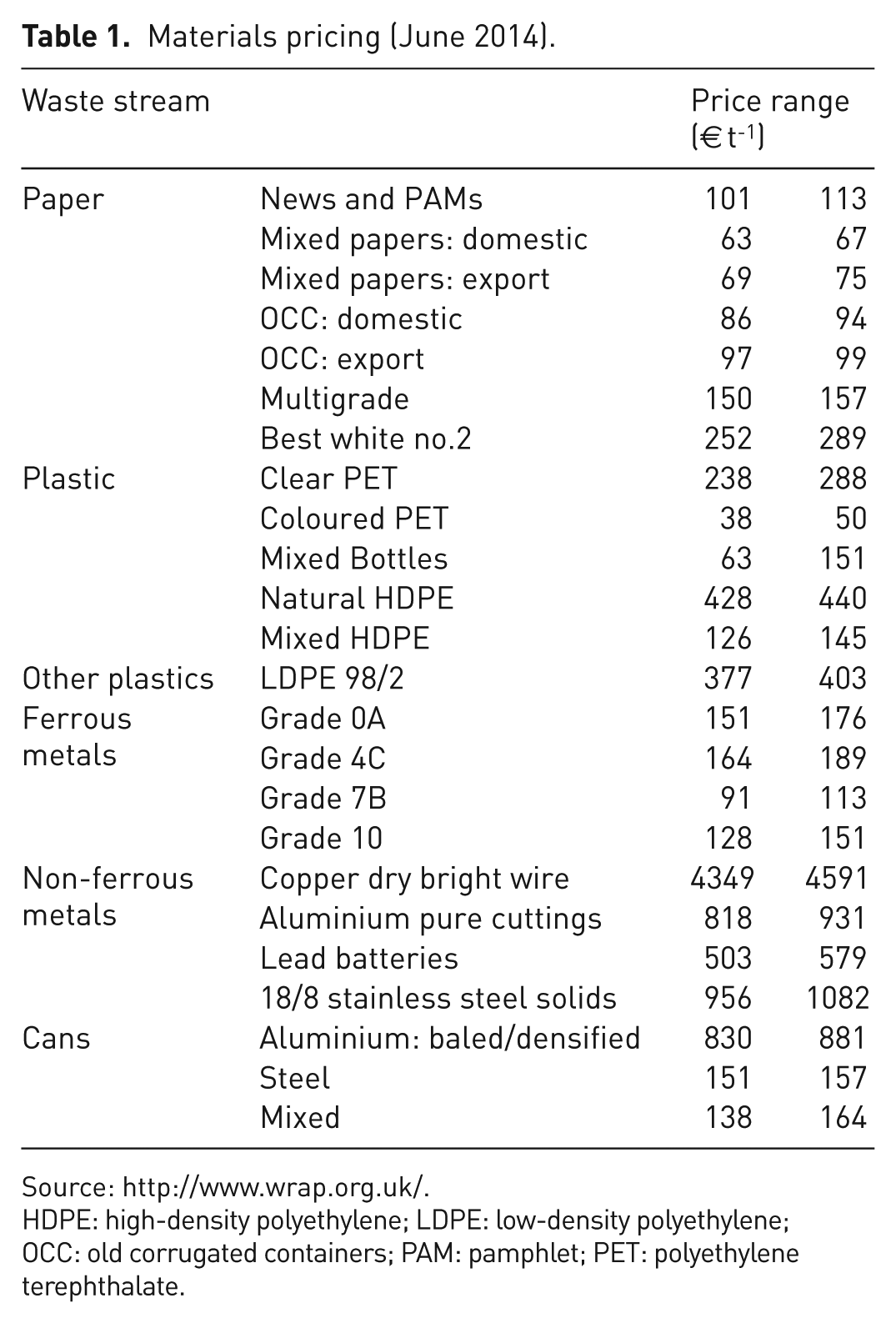
Source: http://www.wrap.org.uk/.
HDPE: high-density polyethylene; LDPE: low-density polyethylene; OCC: old corrugated containers; PAM: pamphlet; PET: polyethylene terephthalate.
Determination of main components
As discussed in the previous section, this ‘miniature’ compressor must: (a) be capable to compress recyclable waste in high ratios; (b) have minimal design; (c) be controlled easily and automatically using only a button; (d) be safe in operation; and (e) be lightweight.
Two major components are required in order to compress the various wastes:
(a) the compression chamber;
(b) the piston/compression foot.
The piston moves on two directions (up and down) using an electrical motor and an oil pump in a closed loop. The hydraulic compression offers very high compression ratios, automated operation and high speed during compression and release of the compressed items. The main chamber (box) must be rigid, lightweight and corrosive resistant. A detachable secondary box is placed in the main box, in order to press and store the wastes simultaneously. At the bottom of the secondary box, a large open is designed for easily removing the compressed wastes. The recycler is covered with a metal cover in order to be electrical protected by water. Finally, four small wheels must be mounted on the main box for easy handling and transportation of the whole equipment.
Final selection of waste streams
Taking the above mentioned into consideration, six different waste streams will be separately sorted:
ferrous containers (e.g. tin cans);
aluminium;
plastic made of high-density polyethylene (HDPE);
plastic containers (such as water bottles);
drink cardboard boxes (such as milk containers);
printed paper (collected, not compressed).
For conducting the simulation of the compression process, a typical four-member family was considered. According to the most recent data provided by Eurostat (2013) (code: tsdpc240), in Greece each person generates around 503 kg of MSW per year, which corresponds to 1.38 kg capita day-1 (2012 data). Thus, a four-member family would generate approximately 5.51 kg of household waste per day, 2.44 kg of which represent recyclable packaging waste.
Typical household waste items considered
In order to design the system, it was necessary to assume a number of recyclable waste items that are generated by a typical four-member household. This data provided the necessary input for the simulation of the compression process (see next section). The simulation involved the generation of a finite element model for specific waste items that are commonly found in a typical household. It was outside the capacity of the study to simulate every waste item that is generated by households, since the waste generation varies significantly by household and consumer preferences. Also, the results depend mostly on the size and type of material simulated, e.g. plastic, hard plastic (HDPE), paper, tin and aluminium.
To this end, it was decided to choose one representative packaging waste for each material (see Figure 2) and then estimate the total effect of all packaging waste generated by a four-member family.
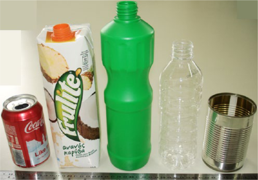
Packaging recyclable household waste simulated and tested.
Based on field data acquired from a visit to existing MRFs within the Attica Region, the following breakdown by material applies.
Metals
This represents approximately 6.2% of the total recyclables collected and transferred to the MRF for separation. The separate waste streams comprise:
aluminium, 10.5%;
ferrous materials, 89.5%.
Plastics
This represents approximately 17.5% of the total recyclables collected and transferred to the MRF for separation. The separate waste streams recovered, include:
Polyethylene terephthalate, 27.3%;
High-density polyethylene, 9.1%;
Polypropylene/polysterene, 13.6%;
Low-density polyethylene, 50%.
Paper
This represents approximately 71.4% of the total recyclables collected and transferred to the MRF for separation. The separate waste streams recovered, include:
cardboard, 29.8%;
mixed paper, 68.3%;
Tetrapak, 1.9%.
Mixed paper includes newspapers, catalogues, flyers, print paper, etc.
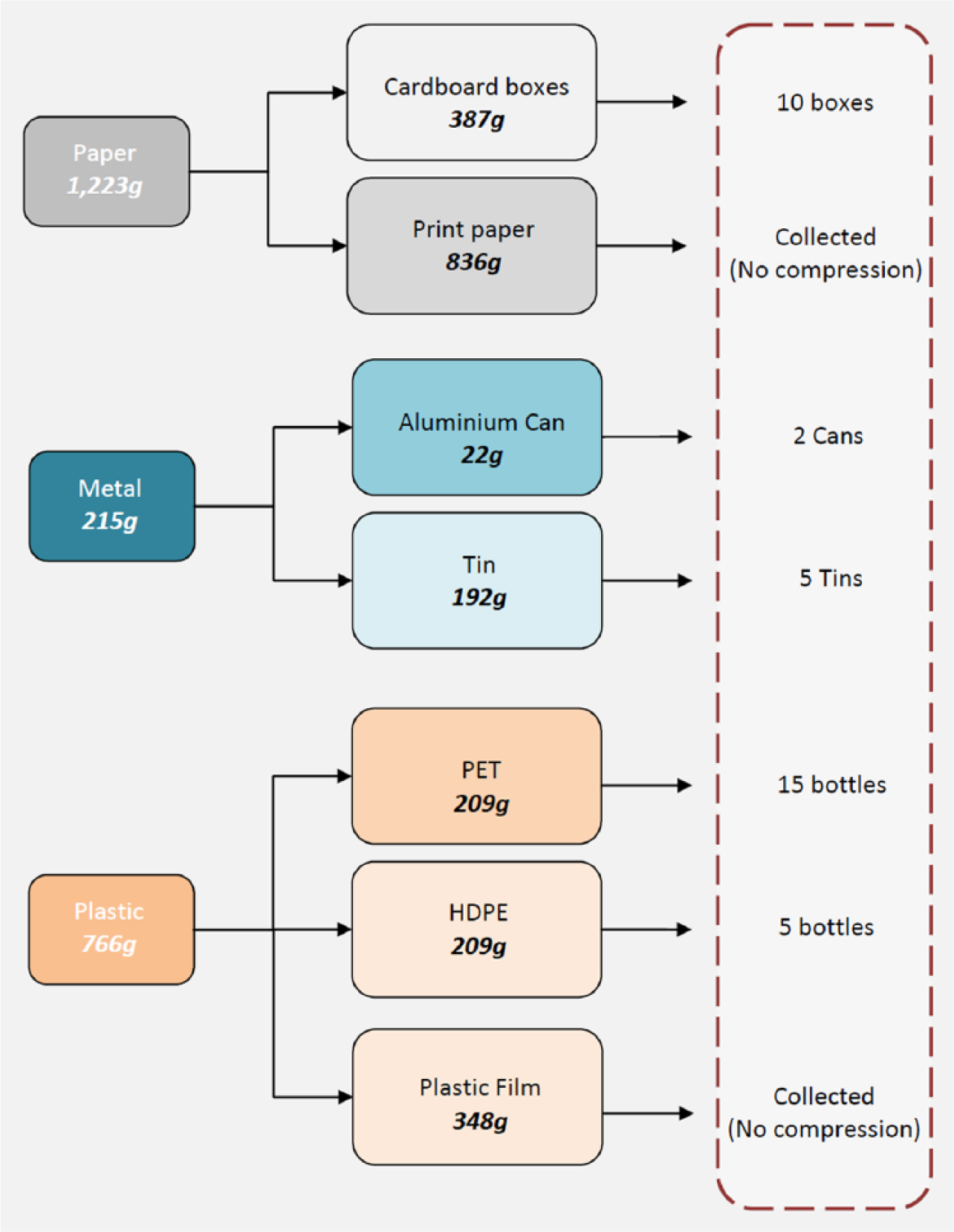
Even though the mass quantity can be safely estimated by the data provided by the MRFs, the number of packaging waste per material is not known. Since the simulation for the design requires the number of packaging waste items generated daily, the simplified daily profile illustrated in Figure 3 was assumed. For translating the mass quantity into waste items, certain typical packaging wastes were used (see Table 2).
Recyclable waste items assumed to be generated in a typical four-member family.
Dimensions and weigh of typical packaging waste used for the design study.
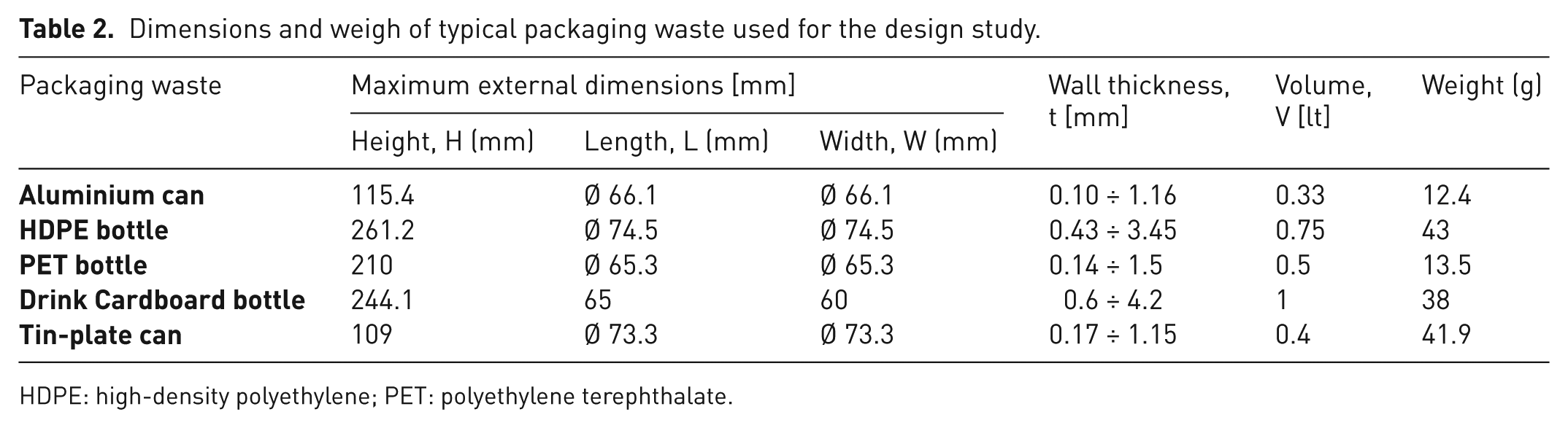
HDPE: high-density polyethylene; PET: polyethylene terephthalate.
For example, for estimating the number of tin cans generated by a four-member family, the following calculation was made.
Metals represent 6.2% of the household recyclable waste produced daily.
A four-member family produces 2.44 kg of recyclable waste daily and, thus, 215 g of metal packaging waste are produced.
Tin (or ferrous metals) represents 89.5% of metals or 192 g.
Since the tin packaging waste considered (see Table 2) weighs 41.9 g, it is assumed that around five tins are produced daily from a four-member family.
Note that the recyclable waste items illustrated in Figure 3 were estimated on the basis that all recyclable waste generated from the household comprises packaging waste material. This assumption results in more recyclable waste items and thus to increased energy requirements for the operation of the prototype system, providing a worst-case scenario for the design calculations.
Simulation of the compression of selected recyclable waste items
This section deals with the implementation of the explicit finite element (FE) Code LS-DYNA to the simulation of the crash behaviour and energy absorption characteristics of the mentioned thin-walled recyclable household waste (i.e. bottles/cans) subjected to static axial compressive loading. The obtained numerical results are compared with the corresponding actual experimental data in terms of deformation modes, energy absorption capability and load-deflection (shortening) history.
Through the experimental procedure, the household waste shells were axially compressed between two parallel steel platens in a fully automated INSTRON 4482 Universal Testing Machine of 100 kN loading capacity (Figure 4), in ‘dry’ boundary conditions. The top end (or bottleneck) was always placed in contact with the upper moving platen, while the lower end was always placed in contact with the down stationary platen. It must be noted that in certain cases, namely aluminium, tin-plate, PET and HDPE bottles/cans, very small holes were cut to prevent air entrapping and compression inside the corresponding bottles/cans during axial collapse experiments. These notches were cut at the strongest areas of the shells (bottleneck, bottom area, top or bottom contour ring) in order not to affect their global mechanical response during tests.
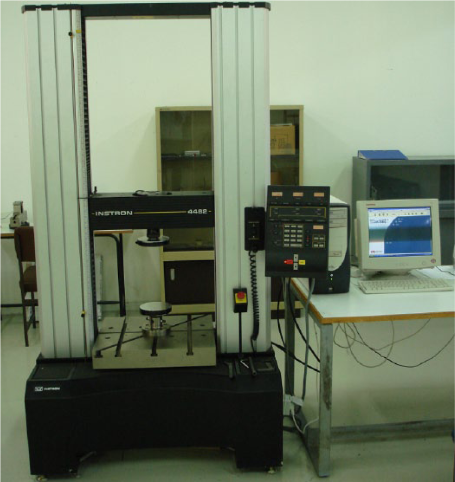
Experimental equipment/set-up.
In order to model the axial compression and the collapse of the waste items, numerical modelling based on finite element method (FEM), namely the explicit FE Code LS-DYNA (Livermore, 2006), was employed. The following main assumption were made throughout the simulation process of such geometrically complex (shape, dimensions, wall thickness distribution) shell structures: geometrical imperfections and material defects, occurred from fabrication inaccuracies or packing and storing conditions of the actual specimens tested, were not taken into consideration, leading to a finite element model configuration based on the typical design concept dimensions. Owing to the lack of manufacturers’ (detailed) engineering drawings and specifications, the geometric representation and measurements (dimensions, wall thickness distribution) of the bottles/cans were carried out manually.
The finite element simulation of the case described was performed in the following steps.
Finite element model generation, types and properties of elements for the various parts of the model.
Material properties creation and assignment.
Contact interfaces definition between the interacting parts and within each of them, individually.
Definition of the boundary conditions.
Both experimental and corresponding simulation results (load–displacement curves and a series of photographs/views of the crushing modes during various crumpling stages of the specimens) are presented in Figures 5 to 10, while the related crashworthy characteristics are tabulated in Table 2.
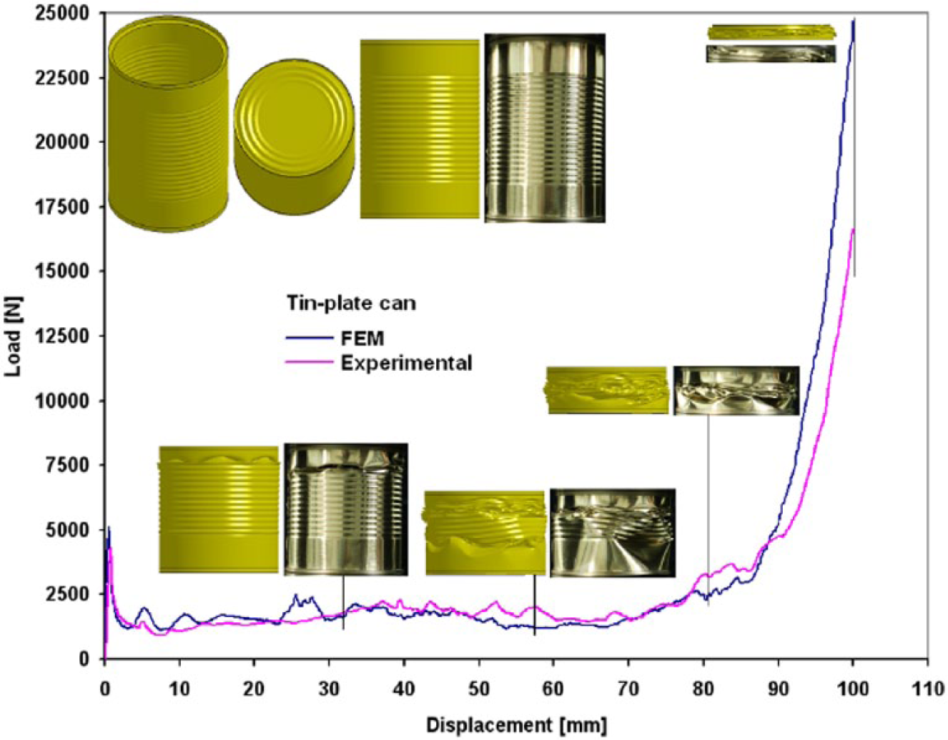
Load–displacement curves (experimental versus FEM analysis) of tin-plate can axial collapse with representative progressive views.
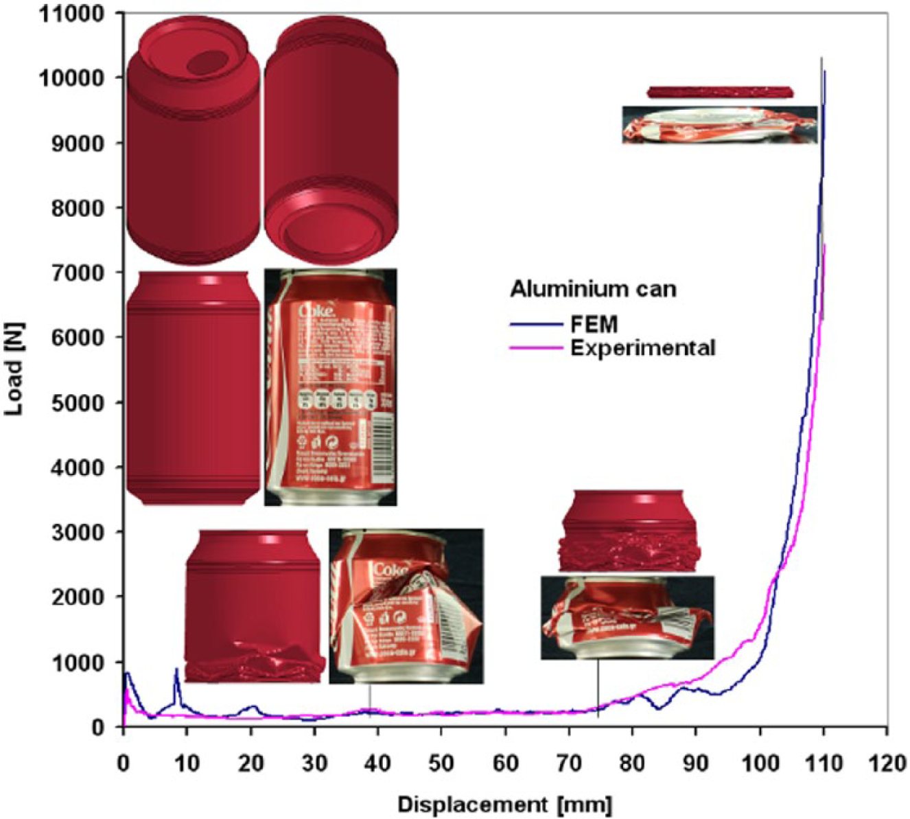
Load–displacement curves (experimental versus FEM analysis) of aluminium can axial collapse with representative progressive views.
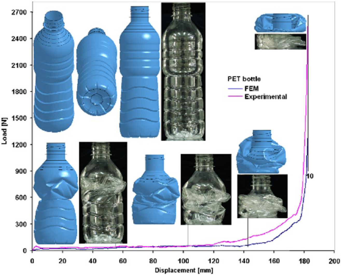
Load–displacement curves (experimental versus FEM analysis) of PET bottle axial collapse with representative progressive views.
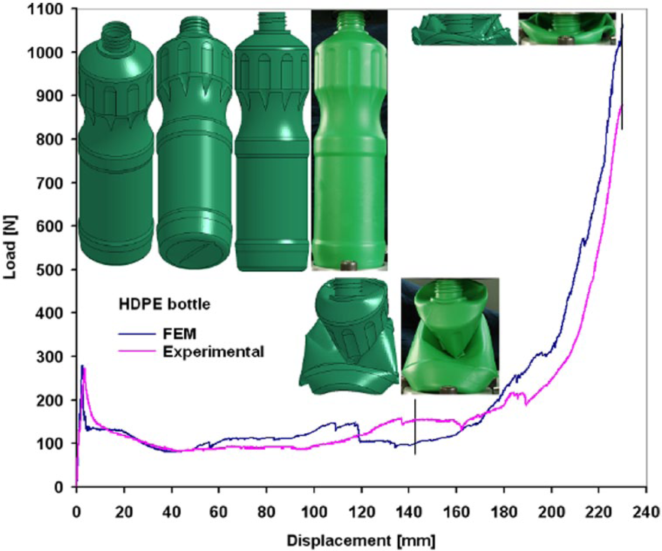
Load–displacement curves (experimental versus FEM analysis) of HDPE bottle axial collapse with representative progressive views.
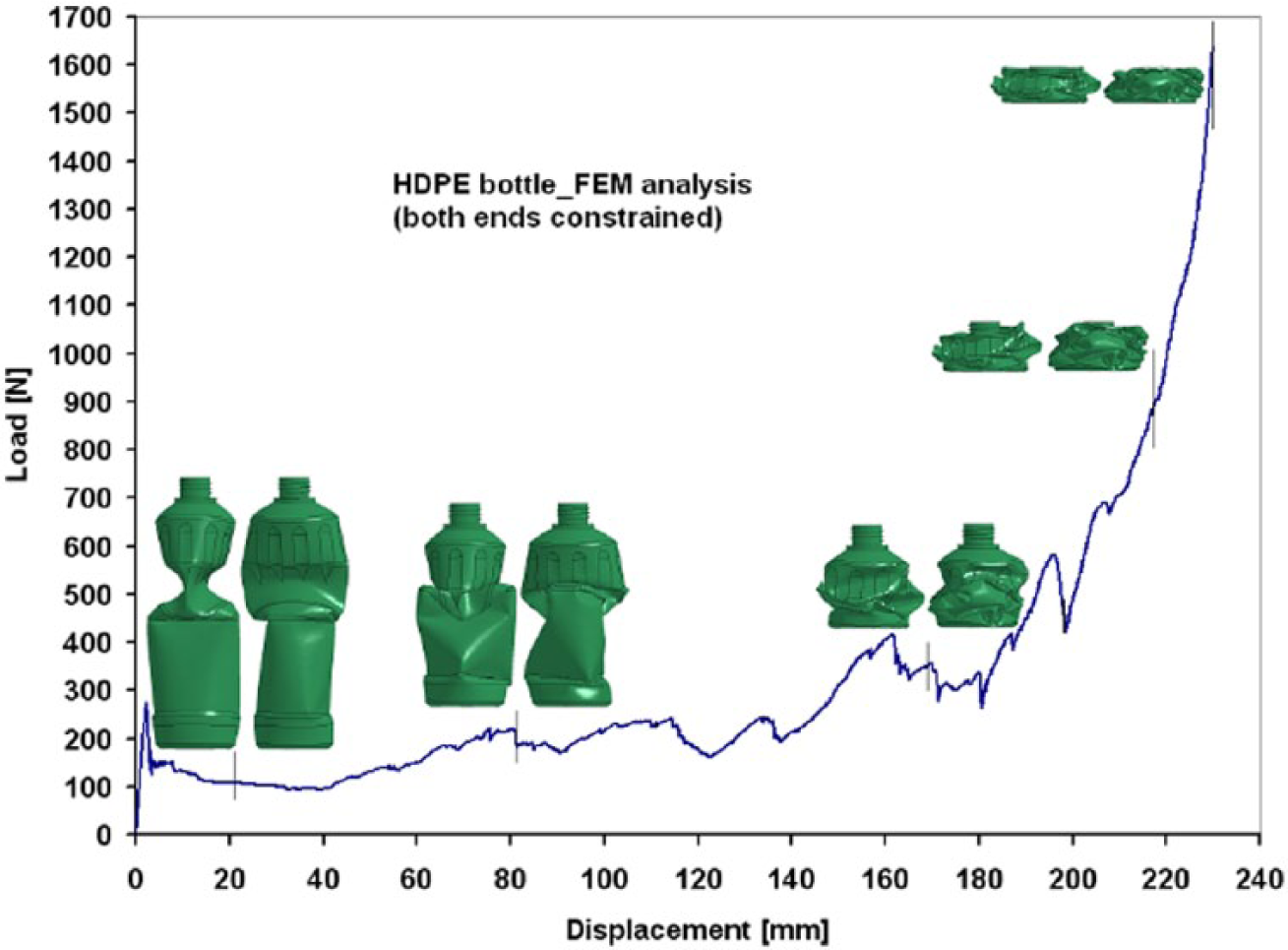
Load–displacement curves (FEM analysis – both ends constrained) of HDPE bottle axial collapse with representative progressive views.
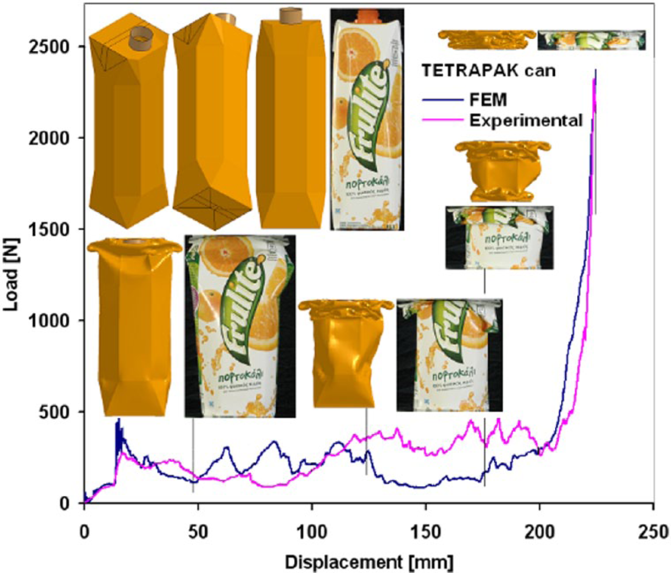
Load–displacement curves (experimental versus FEM analysis) of Tetrapak can axial collapse with representative progressive views.
As far as the deformation mechanism – in the various crumbling stages during testing and simulation – is concerned, in almost all the bottles/cans examined herein, some common characteristics are apparent.
Initially, the shell behaves elastically and the load rises at a steady rate up to an initial peak load.
At this first peak load, the material yielding begins at the weakest region (cross section) of the shell and as instability develops, the load falls off rapidly, in a manner similar to that of column-buckling, while a fold into a non-axisymmetric (‘diamond’) type of failure is developed, which then proceeds to deform to its greatest degree.
While deformation proceeds with subsequent loading, the shell post-buckling phase initiates, where the initial plastic non-axisymmetric buckle is followed by similar collapse patterns in the neighbouring regions (the non-axisymmetric folds succeed each other), depending on the whole geometric configuration and wall-thickness distribution of the shell (Figures 5 to 10). Measurement of the formed circumferential lobes at any level indicates no significant increase in the circumference (inextensional mode of collapse).
The post-buckling region of the load–deflection/displacement curve is characterised by a series of fluctuations about a mean post-buckling load (up to the last phase of compression where the load increases rapidly owing to the compression of the most stiff – with the largest thickness – regions of the shell). The peaks and troughs are directly related to the formation of buckles and folding at the various buckling levels (Figures 5 to 10). The mean post-buckling load is determined from the plastic work done (absorbed energy Eabs, see Table 3), by measuring the area under the load–deflection curve (Eabs) for the post-buckling region and dividing it by the corresponding deflection (or punch advance/displacement). The secondary peak loads are lower in magnitude compared with the initial one, but of increasing magnitude as the compression (deformation) proceeds in its final phase.
Although the buckling and instability are synonymous from a mechanics point of view, the folding and stretching that accompanies a propagating buckle does not lead to geometric instability in general (except the HDPE global buckling owing to the down end boundary conditions – low friction and sliding) because the mean collapse load – of each folding at the various buckling levels – in the post-buckling region of the load–deflection curve is approximately constant throughout the entire collapse process (Figures 5 to 10). In the case of HDPE bottle axial collapse, global buckling – after some local deformation – and sliding on the compression platens were occurring. In order to circumvent these phenomena, a metallic plug was inserted to the bottleneck and a metallic ring was fixed around the bottom of the bottle (see Figure 8). However, the under axial compression mechanical response of the shell has still resulted in global buckling owing to its geometric configuration. From an FEM modelling examination point of view, both ends constrained boundary conditions were enforced in the HDPE bottle (by ‘tying’ the top – bottleneck – and the bottom of the shell to the compression platens) to provoke steady and progressive axial collapse without global buckling (see Figure 9).
The experimentally observed and proposed prevalent failure mechanism of inextensional plastic collapse and the above-mentioned macroscopic effects seem to be verified with very good accuracy by numerical FE analysis using LS-DYNA code, for all specimens modelled, giving quite similar failure mode configurations. A comparison between the relevant load–displacement curves obtained from the simulation process and the corresponding experimental ones (Figures 5 to 10) indicates that FEM modelling estimates with good accuracy the load history and energy absorption (i.e. mean buckling load) of the axially crushed bottles/cans (Table 3). Some minor discrepancies between experimental and simulation results (particularly in the case of a PET bottle), such as number and pattern of buckles or plastic deformation sequence along the specimen axis, variation of buckling load with the amount of compression (arrangement of fluctuations and position of final – highest – compression phase) and also crashworthy characteristics values (absorbed energy) may be attributed to the following modelling and specimens parameters: manual geometric representation and measurements (dimensions, wall thickness distribution) of the bottles/cans, mesh density/distribution of specimens discretisation, implementation of a higher loading speed compared with the experimental one (due to the ‘explicit’ formulation of the FEM code used), assumptions about the contact and relative sliding between interacting parts and also material defects and geometrical imperfections and discontinuities occurring in the specimens during their fabrication or packing and storing. However, some assumptions and simplifications have always to be considered for an effective FEM analysis in a reasonable amount of Central Processing Unit (CPU) time with no significant loss in accuracy.
Total daily energy requirements of the prototype system.
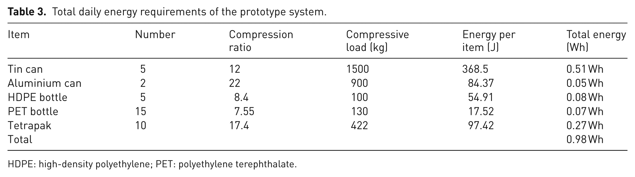
HDPE: high-density polyethylene; PET: polyethylene terephthalate.
Energy considerations
Based on the aforementioned results of the simulation, the total energy requirements for the compression of the daily produced and source-separated packaging waste, through the use of the prototype, were estimated at 0.98 Wh (see also Table 3).
Design and stress analysis of the home recycling unit
The home recycler (compressor) consists mainly of: (a) the main box); b) the compressor element and hydraulic piston; (c) the detachable secondary box; (d) the cover; (e) plastic wheels; and (f) the electrical/hydraulic system (see Figure 11 and Appendix). The compressor is capable of compressing various types of wastes simultaneously, using the secondary box, or one by one, without the use of the secondary box. The recyclable waste items can be mounted at any region of the main box without possible failure of the structural elements. The total cost, the weight and the practicality constitute the most important design criteria. The total cost is related to the assembly, material, machinability, dimensions, maximum force and environmental factors. The dimensions of the main and secondary boxes were calculated according to the maximum waste dimensions and the waste volume, as can be seen in Figure 12. The compressibility of five different types of wastes has been investigated. The maximum applied force was calculated taking into consideration the elasto-plastic numerical analysis of the various types of wastes, and was set equal to F = 15,000 N. The compression force leads to different compression ratios according to the previews numerical and experimental results. The compression ratios (CR) for various materials are: (a) CR(Tin) = 12; (b) CR(Al) = 22; (c) CR(HDPE) = 8.4; (d) CR(PET) = 8; and (e) CR(Tetrapak) = 17.4. According to Figure 12, each secondary box can store: (a) 7 kg of Tin; (b) 5.6 kg of Aluminium cans; (c) 1.6 kg HDPE bottles; (d) 1 kg of PET bottles; or (e) 4.5 kg of Tetrapak.
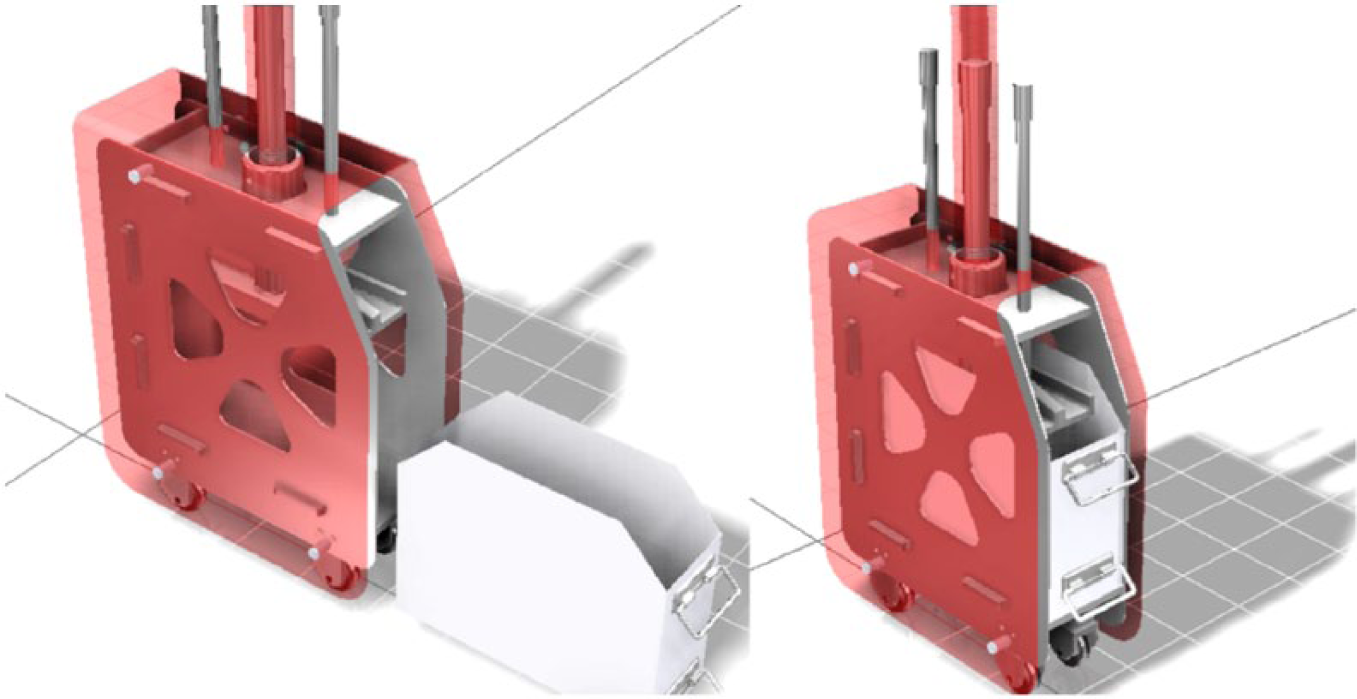
Drawing of the recycler compression system.
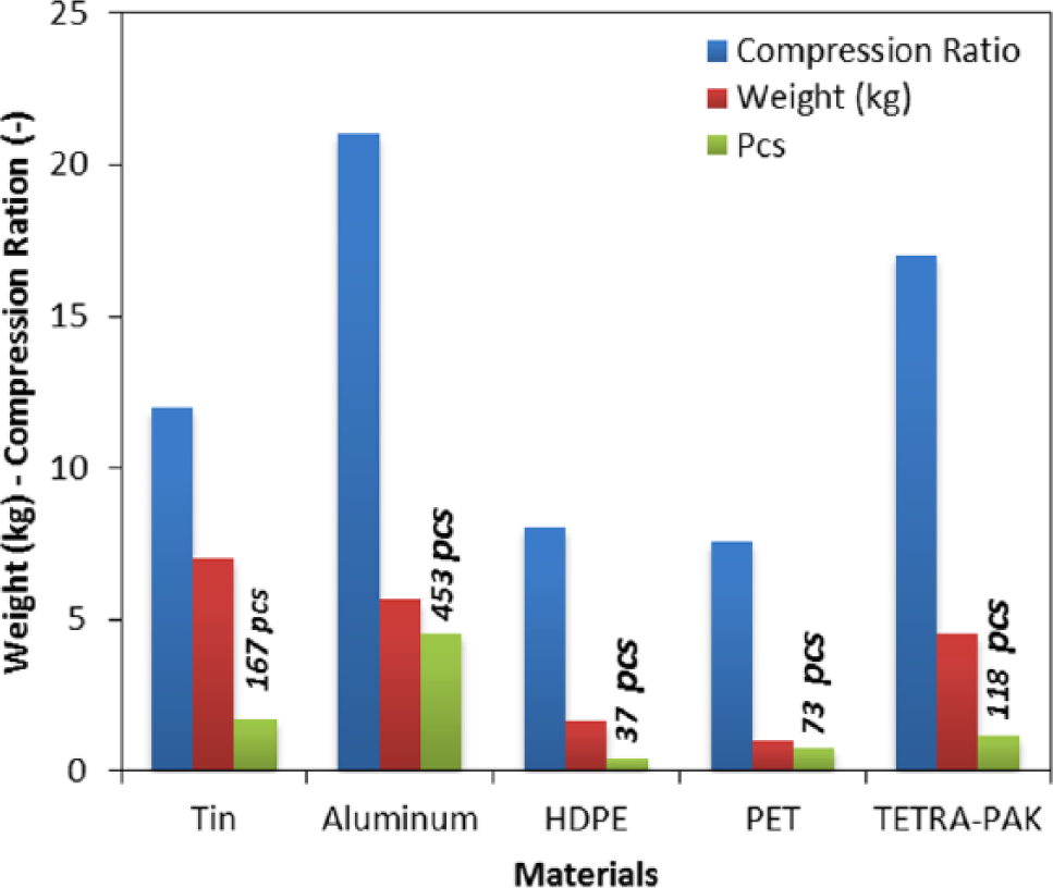
Total stored items and compression ratios for each type of waste.
A puzzled assembly approach was adapted in order to avoid extra tooling costs and assembly apparatuses. The puzzle parts can be assembled very fast and can be locked using special hedges or spot welding. The minimum thickness of the parts was determined using FEM software, concerning the maximum deflection and the overall safety factor of the compressor. The importance of the material selection of each part of the compressor is crucial. The device’s materials must be resistant to weather conditions, salt and water, and must be well designed in terms of aesthetics. For the aforementioned reasons Aluminium 6065 and Plexiglass were selected for the majority of the parts.
The maximum applied force was applied as described next, Figure 13. The worst-case scenario was examined, in order to predict the maximum stress and the minimum safety factor of the recycler. For this reason the force was placed off-axis, because it is very unpractical to put the waste exactly at the centre of the compressor each time.
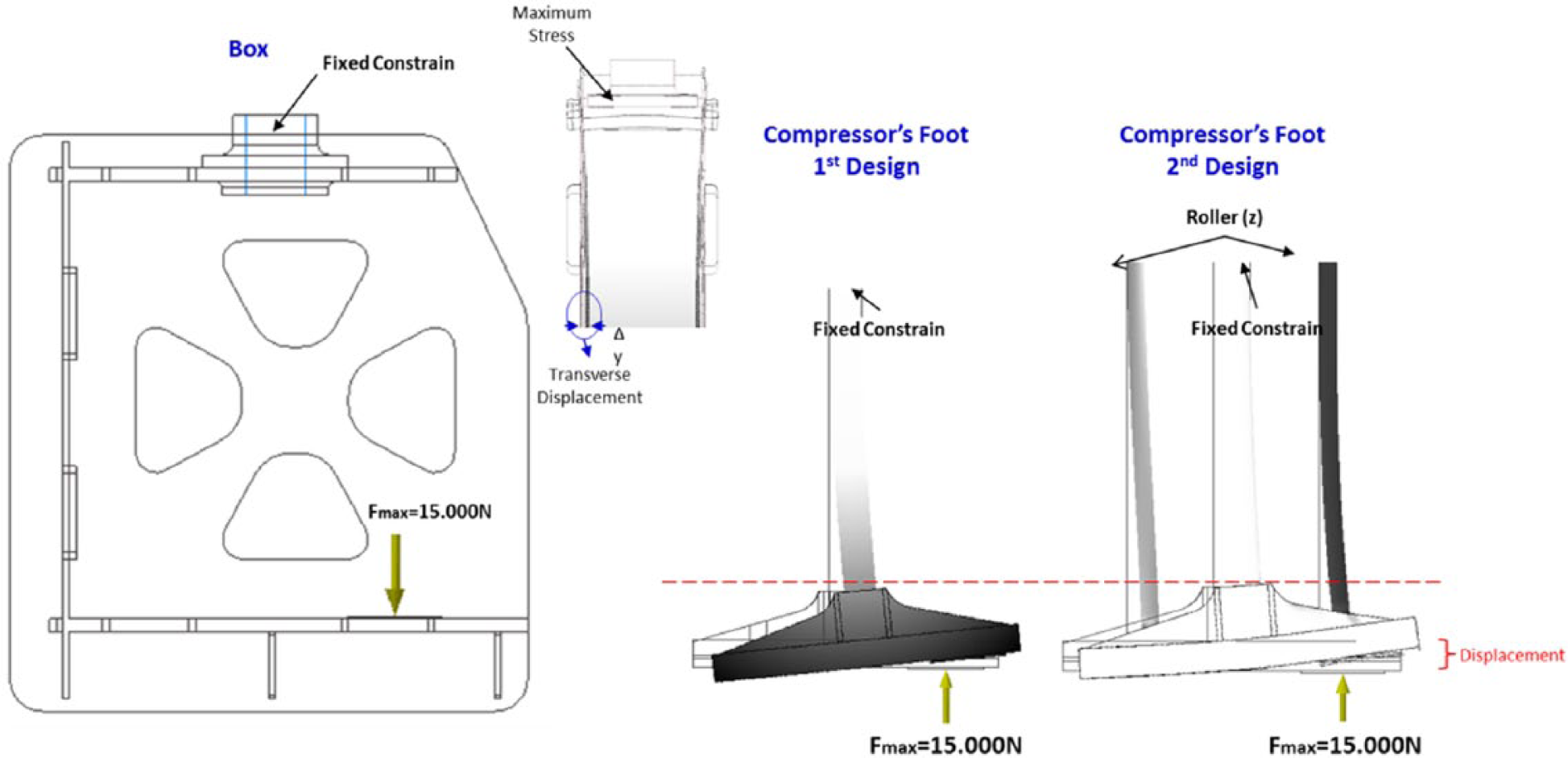
Applied force and constrains.
Two different design approaches were studied, regarding the piston and compression element, because of the worst case approach (off-axis load) in order to avoid high deformation and stresses during compaction.
The main box and the piston/compression element were modelled using FEM software. The main box consists the 75% of the overall system material. For this reason, the reduction of total weight is correlated strongly to the reduction of the main box’s weight. The main box was optimised concerning the thickness of Parts 1, 2 and 3 (Figure 14). An initial guess regarding the thickness of each part was assumed. After the first simulation, the maximum stresses were located (as expected) near the fixed constrain taken a value at 180 MPa using Aluminium’s 6065 material properties.
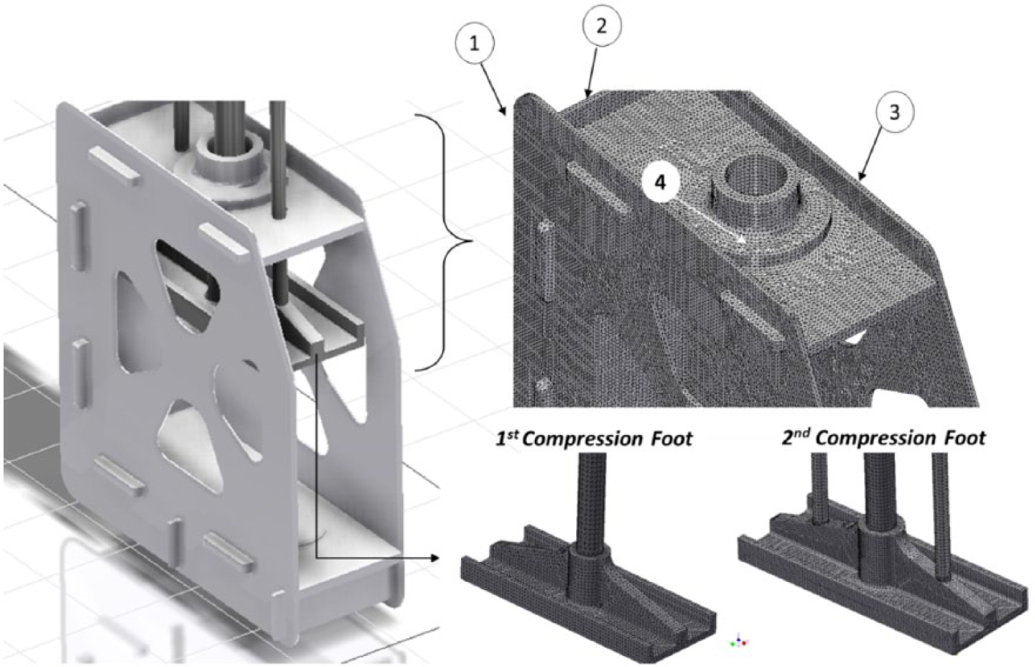
Compressor system and meshing of the main box and the two different design approaches of the piston/compression element.
The stress fields at Parts 1, 2 and 3 are at low levels in comparison with Part 4, where the maximum stress was presented. For the aforementioned reasons, the thickness of Part 4 remained constant and the thickness of the Parts 1, 2 and 3 was reduced from 5 mm to (a) 3 mm to (b) 2 mm. The overall safety factor and the displacement of Parts 1 and 2 was examined in order to avoid contact with the secondary box. The overall safety factor was reduced from 1.51 to 1.13 (Figure 15). Setting a minimum safety factor equal to 1.1, the minimum thickness of Parts 1, 2 and 3 can be determined and is equal to 1.8 mm.
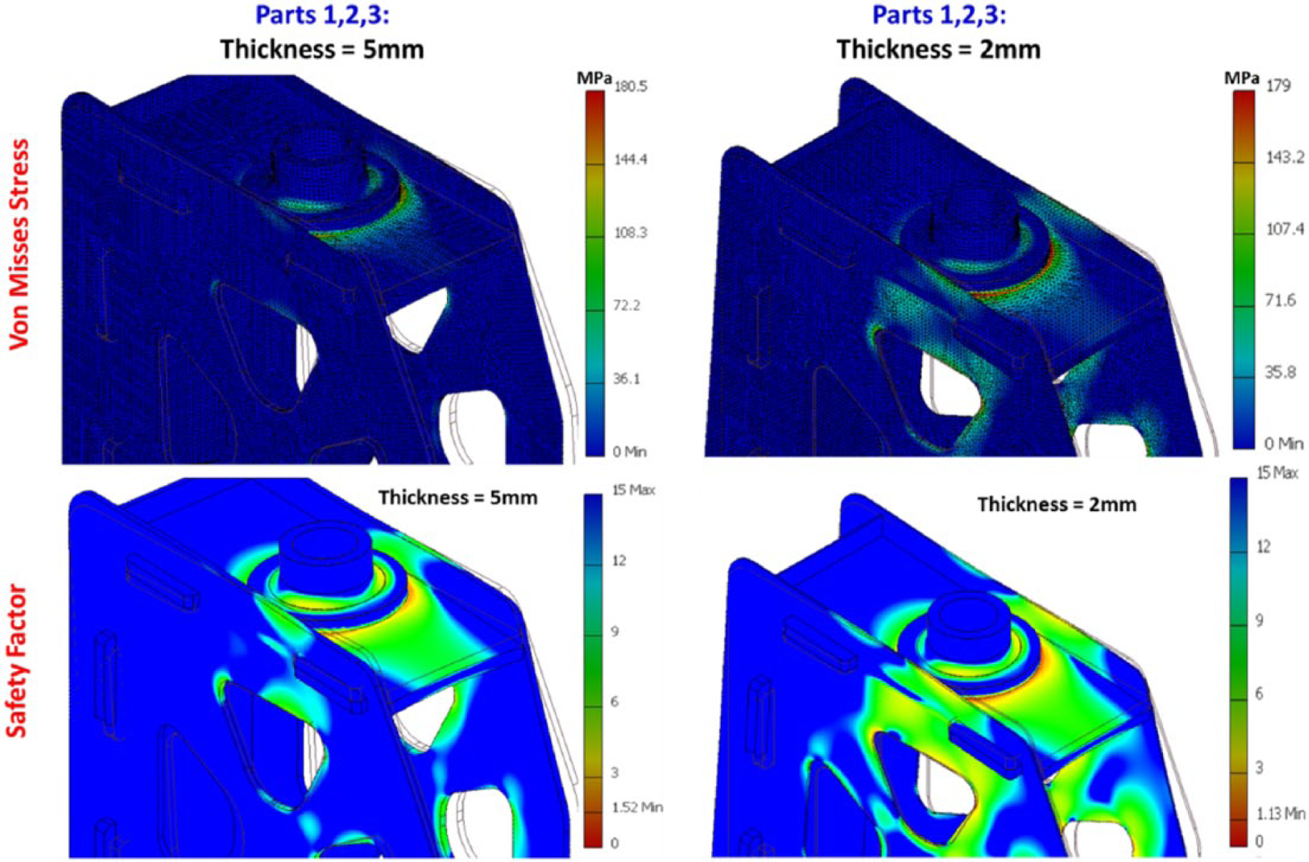
The calculated Von Mises stress and safety factor for the thicknesses (a) 5 mm and (b) 2 mm.
The main box and the piston/compression element were modelled using FEM software. The main box consists the 75% of the overall system material. For this reason, the reduction of total weight is correlated strongly to the reduction of the main box’s weight. The main box was optimised concerning the thickness of Parts 1, 2 and 3 (Figure 14). An initial guess regarding the thickness of each part was assumed. After the first simulation, the maximum stresses were located (as expected) near the fixed constraint value at 180 MPa using Aluminium’s 6065 material properties.
The stress field at Parts 1, 2 and 3 is at low levels in comparison with Part 4, where the maximum stress was presented. For the aforementioned reasons, the thickness of Part 4 remained constant and the thickness of Parts 1, 2 and 3 was reduced from 5 mm to (a) 3 mm to (b) 2 mm. The overall safety factor and the displacement of Parts 1 and 2 were examined in order to avoid contact with the secondary box. The overall safety factor was reduced from 1.51 to 1.13 (Figure 15). Setting a minimum safety factor equal to 1.1, the minimum thickness of the Parts 1, 2 and 3 can be determined and is equal to 1.8 mm.
The displacement (Δly) of Parts 1 and 2 was almost equal for all the cases (0.42–0.44 mm) as shown in Figure 16.
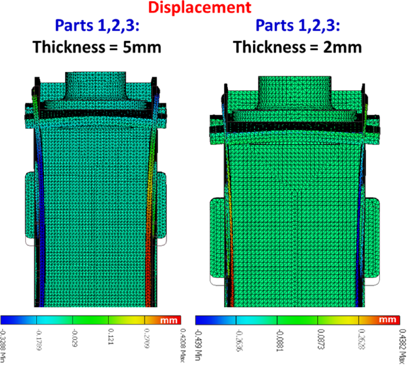
Displacement of the main box at Δy for the two different thicknesses 5 mm and 2 mm.
The stress field at the piston/compressor regarding the first approach is very high, with maximum stress equal to 639 MPa. Furthermore, the maximum displacement is approximately equal to 8 mm. The second design approach leads to a significantly lower stress field (see also Figure 17). The piston and compressor materials were steel and Aluminium 6065, respectively.
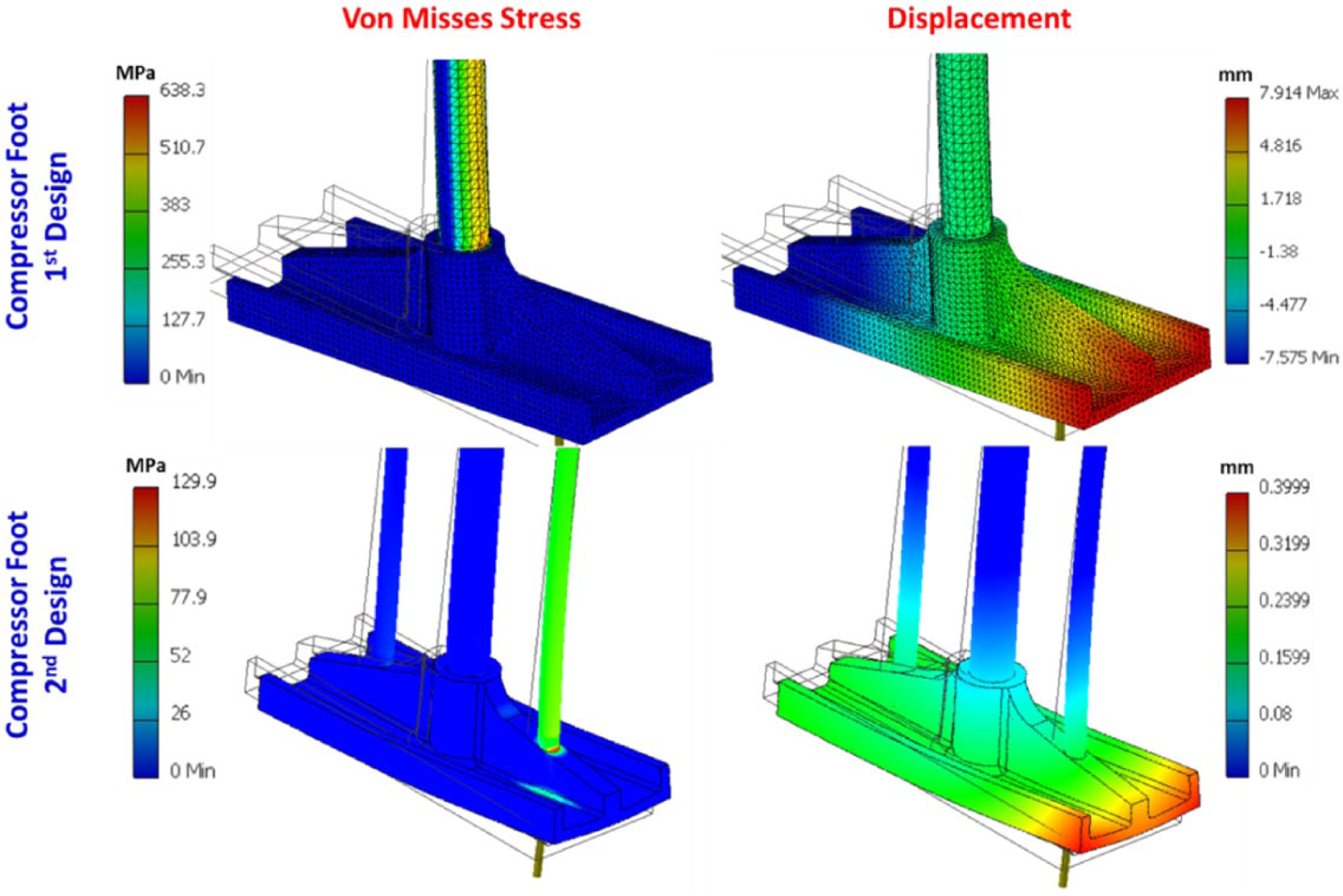
The calculated Von Misses stress and displacement of the piston/compression element.
Setting an overall safety factor equal to 1.1, the predicted allowed thickness of Parts 1, 2 and 3 is equal to 1.8 mm. The initial guess of the parts (1, 2 and 3) thickness was 5 mm and the final used thickness is 1.8 mm (see also Figure 18). This leads to a significant weight and cost reduction of the device without any other discrepancies between the assembled parts (deformations, maximum stresses, functionality, etc.). More specifically, the weight reduction is equal to 37%, in comparison with the initial guess, with a similar material cost reduction percentage. The total weight of the main box is only 4.8 kg.
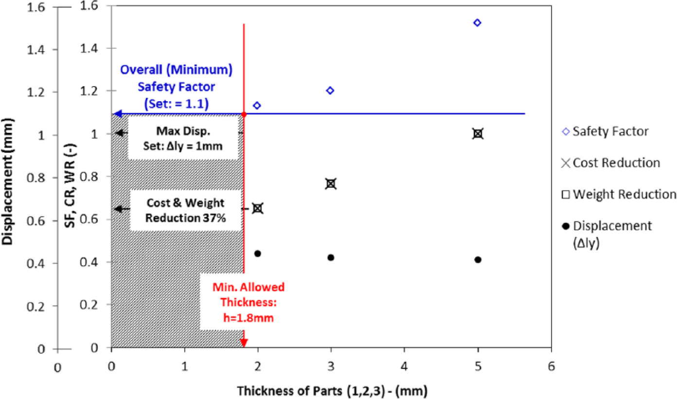
Calculation of the minimum thickness as a function of safety factor and cost/weight reduction of the main box.
Conclusions
This article presents the design of an innovative household device for the source separation and compression of household packaging waste.
The design was based on the following.
Coherent assumptions about household MSW synthesis and recyclable items generated daily.
Simulation of the compression process of the household recyclable waste (FEM analysis with LS-DYNA) in order to determine accurately the developed forces and the compression ratios.
Finite element analysis of the home recycling unit during the process using INVENTOR and COMSOL software.
With reference to the simulation of the compression, the mechanical response of thin-walled aluminium, tin-plate, PET, HDPE and Tetrapak bottles/cans subjected to axial plastic collapse has been studied and analysed both experimentally and numerically. The inextensional pattern mechanisms were the prevalent deformation modes in the specimens tested. The implementation of the ‘explicit’ FE Code LS-DYNA to simulate crush behaviour was found in good agreement with the corresponding actual experimental data.
With reference to the stress analysis, the minimum safety factor was determined as a function of material thickness, weight and materials’ cost for a specific design approach. The developed maximum displacements at crucial regions are in low levels in order to avoid any dysfunctionalties regarding the movement of the various parts.
Overall, the Recycling@Home system comprises an innovative solution for source separation and pretreatment of MSW that can easily be integrated at a household level. It is ideally suited for sparsely populated areas, where high transportation costs predominate. The energy requirements for its operation are less than 1 kWh per year for a four-member family, while it is very user-friendly.
Footnotes
Appendix
Declaration of conflicting interests
The authors declare that there is no conflict of interest.
Funding
This work has been carried out within the framework of the LIFE+ European project entitled ‘Development and demonstration of an ecological, innovative system for in house waste recycling’ (LIFE11 ENV/GR/000950) with the acronym Recycling@Home. Financial support by the European Commission under the European financial instrument for the environment, LIFE+, is gratefully acknowledged. The results of the project are available at: ![]() .
.