
Abstract
To evaluate thermal protective performance of fire proof garment under flash fire exposures, it is important to discuss garment heat transfer characteristics eliminating the effect of air gaps between garment and body. In this study, a test of flame manikin clothed with close-fitting garment was designed. And a three-dimensional transient heat transfer computational fluid dynamics simulation of the test was achieved to gain the garment surface temperature. By means of three-dimensional body scanner, Geomagic and Gambit software, we developed a method of three-dimensional geometrical modeling of the full-scale close-fitting clothed manikin. The accuracy of the computational fluid dynamics simulation was validated by actual experiments. It was found that the average incident heat flux to the exterior of the Nomex® IIIA garment is not 84 kW/m2, the value measured in nude manikin tests, but the value is 11% lower than it. This will help to set more accurate boundary conditions on garment surface in further simulations.
Keywords
Introduction
Advances in numerical computation have found increasing applications in assessing the thermal protective performance of fabrics during flash fire exposures. 1 Because realistic fire exposure environment can be provided in manikin chamber, flame manikin tests were regarded to be the only one test which can evaluate the overall performance of a firefighter’s turnout suit.2,3 But the non-uniform distribution of air gaps 4 between garment and body makes it hard to simulate the heat transfer through garment and air gaps by numerical simulation. For simplification, most heat transfer models which have been made up to now are one-dimensional. Heat is assumed to travel only in the direction perpendicular to the garments, and the transverse temperature gradients in the garments are neglected.5–7 For example, Song et al. 6 developed a one-dimensional difference model to simulate the heat transfer through garment, air gap, and human skin for the PyroMan instrumented manikin protective garment evaluation system. Jiang et al. 7 developed a general-purpose computational fluid dynamics (CFD) program that computes the fluid flow and heat transfer in an in situ fire event; however, the program that calculated the radiative–conductive heat transfer through the clothing and human skin was still one-dimensional.
In practice, under the simulated fire environment where the exposure is neither constant nor uniform over the surface of the manikin/garment, 3 the assumption that there are no transverse temperature gradients in the garments deviates considerably from the reality. Furthermore, the non-uniform distribution of clothing air gaps makes the heat transfer mechanism more complex. 8
On the other hand, although air gaps existing in protective garments play a very important role in providing thermal insulation when exposed to flash fire conditions, the role of the garment itself allow of no neglect. From the perspective of guiding for the thermal protection performance design of firefighter’s garments, the heat transfer characteristics of clothing itself have great significance in the research area of garment’s thermal protective performance.
Given this context, in order to study the thermal protective performance of fire proof garment itself under flash fire exposures eliminating air gaps effect, we attempted to design a close-fitting clothed manikin test based on Donghua flame manikin system in this research. As no information on garment surface temperature or heat flux can be obtained by means of only manikin tests, we conducted the full-scale three-dimensional (3D) transient CFD simulation of the test of flame manikin clothed with one-layer close-fitting garment made of Nomex® IIIA to gain the garment surface temperature. A method of geometrical modeling of the manikin clothed with close-fitting garment using a non-contact 3D body scanner, Geomagic studio and Gambit software, was developed in this study. And the prediction results were validated by comparing with the measured data of the clothed manikin tests.
Experimental
Donghua flame manikin protective clothing analysis system
Donghua flame manikin protective clothing analysis system, 9 which meets the requirements of both American Society for Testing and Materials (ASTM) F1930:2013 2 and International Organization for Standardization (ISO) 13506:2008, 3 was used in this study. The burn chamber is equipped with one flame manikin body and six sets of two burners around the body. The average incident heat flux density to the naked body can be 84 kW/m2. The instrumented manikin is made from glass fiber–reinforced ceramic matrix composite materials 9 and is equipped with 135 heat flux sensors distributed over its surface. Figure 1 shows the locations of sensors. These heat sensors are used to measure the heat flux variation with time and to determine the total energy absorbed over the data-gathering period. The information on the location of sensors is used to estimate the extent and nature of skin damage that a person would suffer under similar exposure conditions in order to evaluate the performance of the garment or protective clothing ensembles.
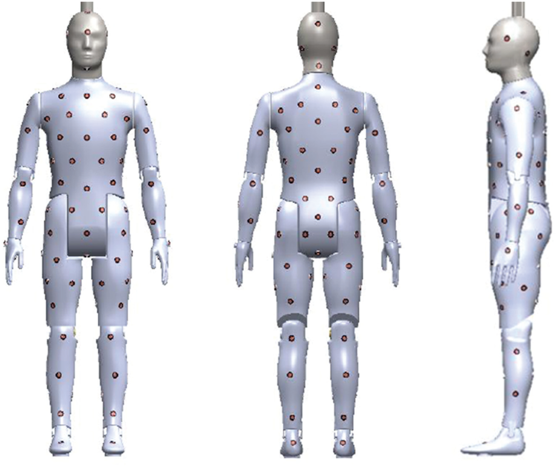
The locations of 135 sensors on the manikin.
Garments
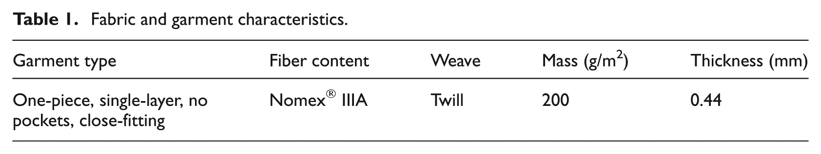
The experimental garments for flash fire testing are one piece, single layer and made from 200 g/m2, Nomex IIIA thermal protective fabrics that were common and commercially available. Details of the garment characteristic are shown in Table 1. In order to eliminate air gap effect, the garment style, as shown in Figure 2(a), is close-fitting and made by draping. Three garments of the identical design are used in manikin experiments.
Fabric and garment characteristics.
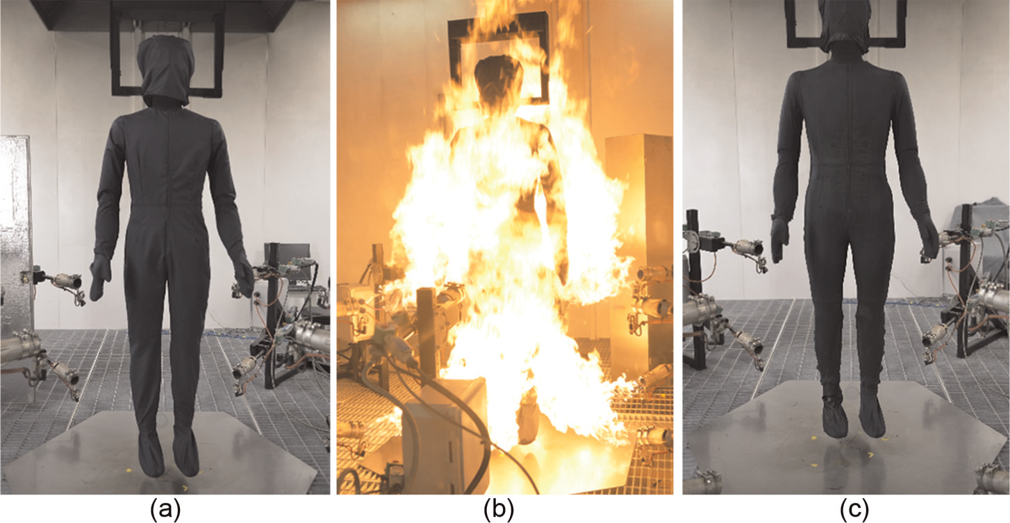
The manikin testing procedures of a close-fitting Nomex® IIIA garment: (a) before the exposure, (b) during the exposure, and (c) after the exposure.
Manikin testing procedure of close-fitting garments
In a typical experiment, the manikin clothed with single-layer garment is engulfed in flames for 4 s and then kept untouched in the room for 60 s. We conducted the naked manikin calibration experiment and three clothed manikin tests of 4-s flash fire exposure in sequence according to ASTM. The manikin testing scenes of a close-fitting garment is shown in Figure 2.
It should be noted that because the feet and hands are not equipped with sensors in ASTM and ISO, the manikin wear gloves, podothecas, and a headgear in our experiments and we mainly focus on the areas covered by the garment. Moreover, only the experimental data during the flash fire are our concern in this research. The CFD simulation, therefore, is only on the transient heat transfer process during the flash fire not including the cooling phase and the skin burn damage prediction.
The experiment is conducted with chamber initial temperature of 20°C ± 3°C, initial humidity of 65% ± 5%, and combustion duration of 4 s. The average heat flux is controlled at 84 ± 2.5 KW/m2, with standard flux variance of no more than 21 KW/m2. The manikin is with a standing posture in three experiments.
In response to the design needs, we assume that there are no air gaps between the garment and the body, even though this ideal state is inaccessible and a few of air gaps exist in the legs and some concave areas, for example, armpits and crotch. It is acceptable because the mean air gap thickness measured based on the 3D scan data of the manikin before and after dressing was only 0.6 mm. Due to thermal-induced shrinkage, the garment after exposure, as shown in Figure 2(c), is even very close to the ideal state of no air gaps. This illustrated that the garments’ experimental data are still appropriate for the validation of following CFD simulation of the heat transfer through the ideal close-fitting garments.
CFD simulation of the close-fitting clothed manikin test
3D geometric modeling of the manikin clothed with close-fitting garment
The numerical manikin, propane burners, and combustion chamber are built based on the prototype of Donghua Flame Manikin system. 10 First, the 3D shape information of the manikin is obtained by a 3D non-contact human body scanner. Since the point cloud gathered by the scanner is mass and disorder, further processing is required. The flow chart of processing is shown in Figure 3.
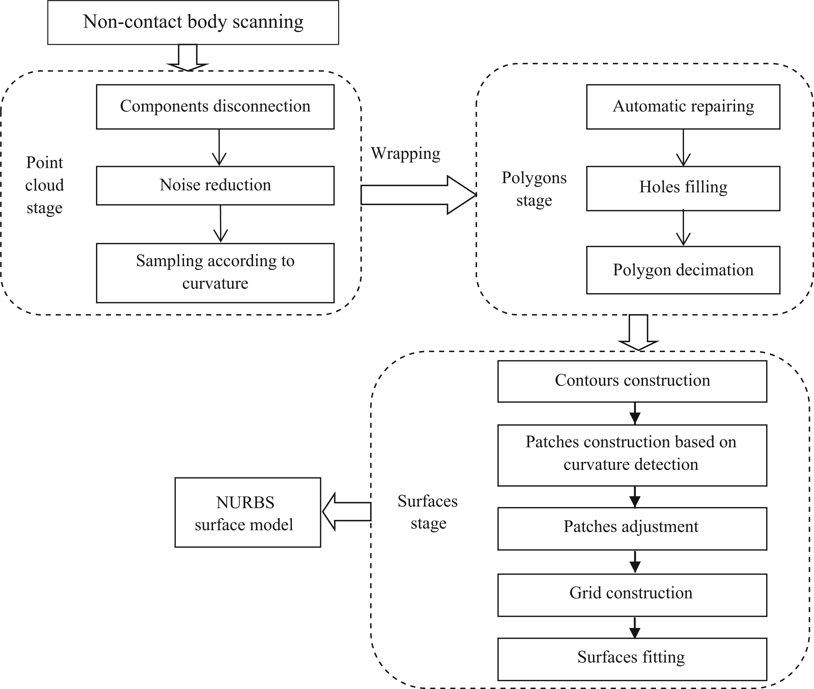
Flow chart of constructing the NURBS surface models.
Using Geomagic studio, a reversing engineering software, the non-uniform rational basis spline (NURBS) surface model of the manikin is created, as shown in Figure 4(b). The surfaces are very smooth, retaining enough characteristics of physiological shape.
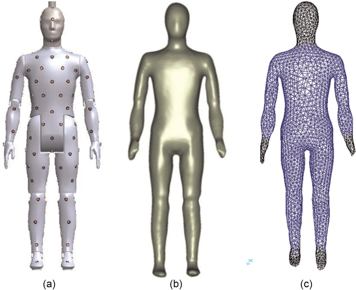
(a) The manikin prototype, (b) three-dimensional NURBS model, and (c) the meshed model of close-fitting clothed manikin.
Second, the full-scale combustion chamber is built using Gambit software and the NURBS manikin model is imported in the chamber. A cube (length 5 m × width 5 m × height 3.05 m) is built for simulating the combustion chamber. The manikin model is adjusted to be in the right place.
Third, 12 cylinders (radius 0.025 m × height 0.15 m) are built in Gambit for simulating 12 burners in 6 groups. The burner geometrical model established with the precise structure consists of two parts: nozzle and ejector, as shown in Figure 5(b). At the exit of the ejectors, 12 cylinders (radius 0.025 m × height 0.03 m) are built for simulating the seed area. Layouts of 12 burners in 6 groups are shown in Figure 5(a).
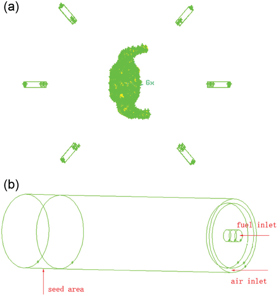
Layouts and structures of 12 burners in 6 groups.
Fourth, the manikin body is divided into two parts: the body covered by clothing and the uncovered parts. The actual operation will produce six individual parts: the head, four limbs, and the torso covered with the clothing, as shown in Figure 4(c).
Fifth, 3D grids are generated to obtain the geometrical grid model of the whole chamber, as shown in Figure 6. In consideration of the complex geometries of the manikin, hexahedral and tetrahedral (unstructured) mesh grids are produced. It is notable that the grids in the inner volume are denser than those in the outer volume because the inner volume is the key domain. The mesh refinement can smooth the node transition throughout the computational domains. The whole computational domain consists of about 4,052,000 grid cells. The maximum degree of grid distortion is 0.801 (<0.9), which means the mesh quality of the model meets the requirement of calculation in Fluent.
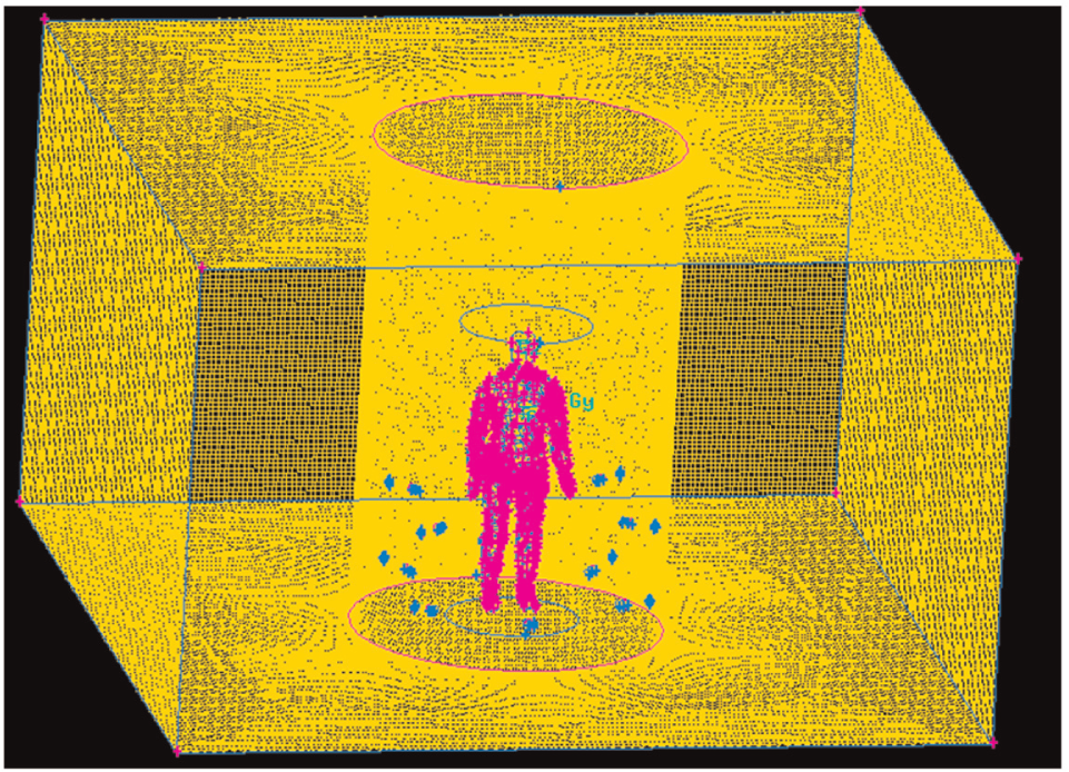
The mesh structure of the whole chamber.
Transient CFD simulation of the clothed manikin test
In this study, Fluent software is used to simulate flow field, heat transfer, and species transport in the naked manikin chamber and in the clothed manikin chamber during the combustion process of 4-s flash fire. Because the flow is time-dependent, the transient, pressure-based solver is used. For better prediction of the spreading rate of round jets, realizable k-epsilon model is selected as the viscous model. The realizable k-epsilon model satisfies certain mathematical constraints on the Reynolds stresses, consistent with the physics of turbulent flows. Detailed model parameters are shown in Table 2.
Numerical scheme (model parameter settings).
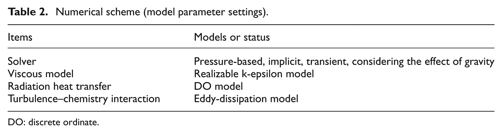
DO: discrete ordinate.
This reaction will be defined in terms of stoichiometric coefficients, formation enthalpies, and parameters that control the reaction rate. The reaction rate is determined assuming that turbulent mixing is the rate-limiting process, with the turbulence–chemistry interaction simulated using the eddy-dissipation model. Considering the front wall of chamber made of heat-resistant glasses is semi-transparent, discrete ordinate (DO) model is used to solve the radiative transfer equation (RTE). The DO model considers the RTE in the direction
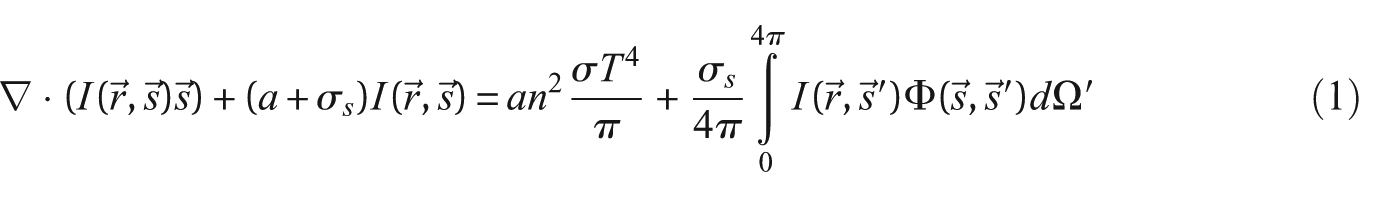
where
For simulation of clothed manikin test, the endothermic and exothermic properties of the garment are very important parameters in determining the outcome because of turbulent flash fire. 11 Considering the thermophysical properties of most protective fabrics under high temperature are found not constant, the specific heat and the thermal conductivity of Nomex IIIA fabric are all defined as piecewise-linear functions of temperature, as shown in Figure 7.
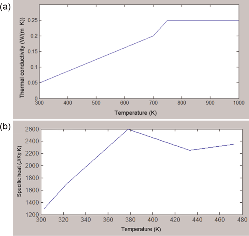
(a) Nomex® IIIA fabric’s thermal conductivity and (b) specific heat used in simulation.
The properties of the manikin body material are as follows: density of 8933 kg/m3,
The coupled algorithm is chosen for the coupling of pressure and velocity. The Green–Gauss node-based method is used as the solution method of the gradient spatial discretization for tetrahedral meshes. The pressure equation is discretized by the body-force-weighted scheme.
Using a time step of 0.02 s, 200 time steps are required for the 4-s flash fire process. Max iterations per time step are set to 15. Because the grid elements number is as high as 4,000,000, a large amount of calculation is required. The computation is executed in a PC by eight CPUs (memory frequency: 798 MHz). It takes roughly 2 days in total.
Results and discussion
Validation of the accuracy of the transient CFD simulation
It is crucial to validate the accuracy of the computed temperature and heat flux field before attaining proper simulations of the heat transfer phenomenon. The accuracy validation of CFD simulation we have done includes two stages. One is the simulation results’ validation of naked manikin test (the calibration test before the clothed manikin test) by comparing with the data of naked manikin test. And the other is the simulation results’ validation of the clothed manikin test using the data of three clothed manikin experiments.
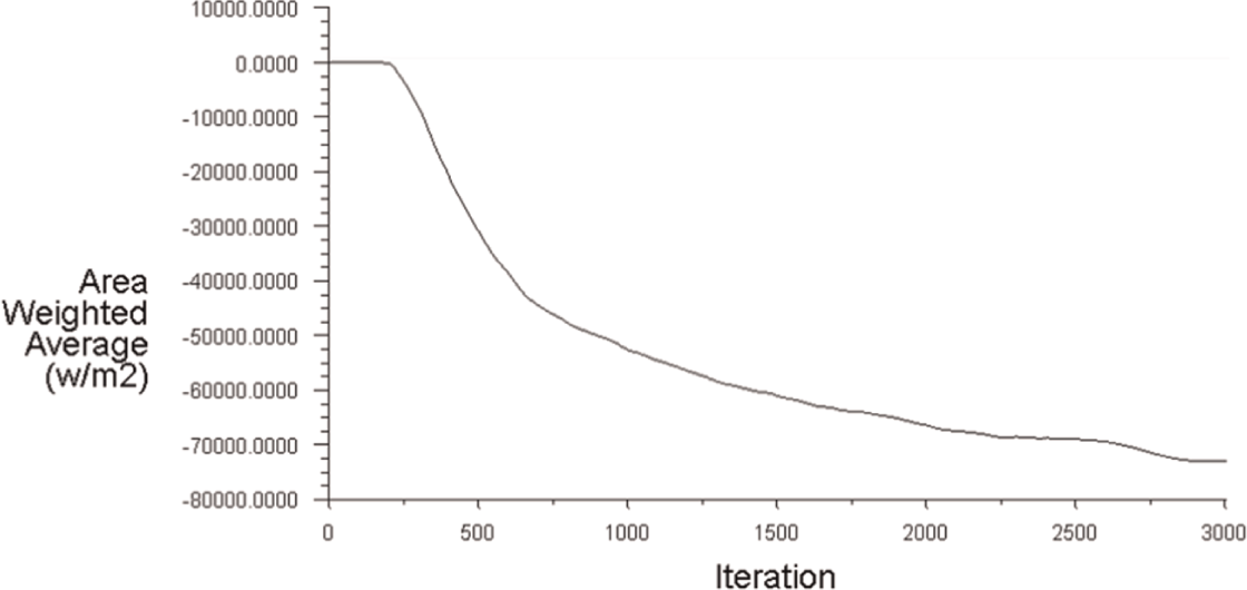
In the first stage, we drew a comparison of the mean heat flux history of naked manikin test simulation with that of an actual experiment during 4-s flash fire exposure, as shown in Figure 8(a). Note that the heat fluxes on the outer surface of the manikin in the iterative process are negative suggesting an endothermic process. Although the heat fluxes measured by sensors are changed to positive, we make these data negative and merge the two curves into one picture for better comparison.
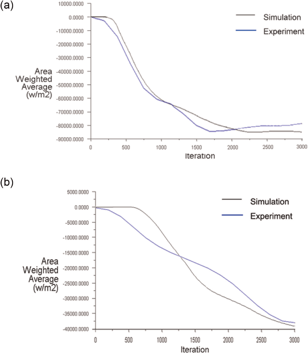
(a) Histories of total surface heat flux on the manikin surface of the naked manikin test and CFD simulation and (b) histories of surface heat flux on the manikin surface of a clothed manikin test and CFD simulation.
There is a steady region of heat flux and the average incident heat flux of the naked manikin surface is stable at 84 kW/m2 in CFD simulation. And the standard deviation is less than 19.3 kW/m2. These values perfectly correspond to the ASTM standard and the experimental results of naked flame manikin. Moreover, the comparison indicates that the overall trend of the total heat flux history on the manikin surface by CFD simulation is very close to the curve of mean heat flux measured by 135 sensors in actual experiments, suggesting that the CFD simulation predicts the heat transfer with a reasonable accuracy.
At the same time, the frequency of heat fluxes at the position of 135 sensors in CFD simulation is analyzed and shown in Figure 9. It is obvious that the intensity of the incident thermal energy is normally distributed over the surface of the manikin being consistent with previous researches. 6 Figure 9 also compares the frequency and cumulative curves of heat fluxes at the position of 135 sensors in CFD simulation with the experimental results. Although there exist some discrepancy of frequency distribution of heat flux between the simulation result and measurement, the cumulative curves of heat fluxes predicted by CFD are consistent with the actual manikin tests.
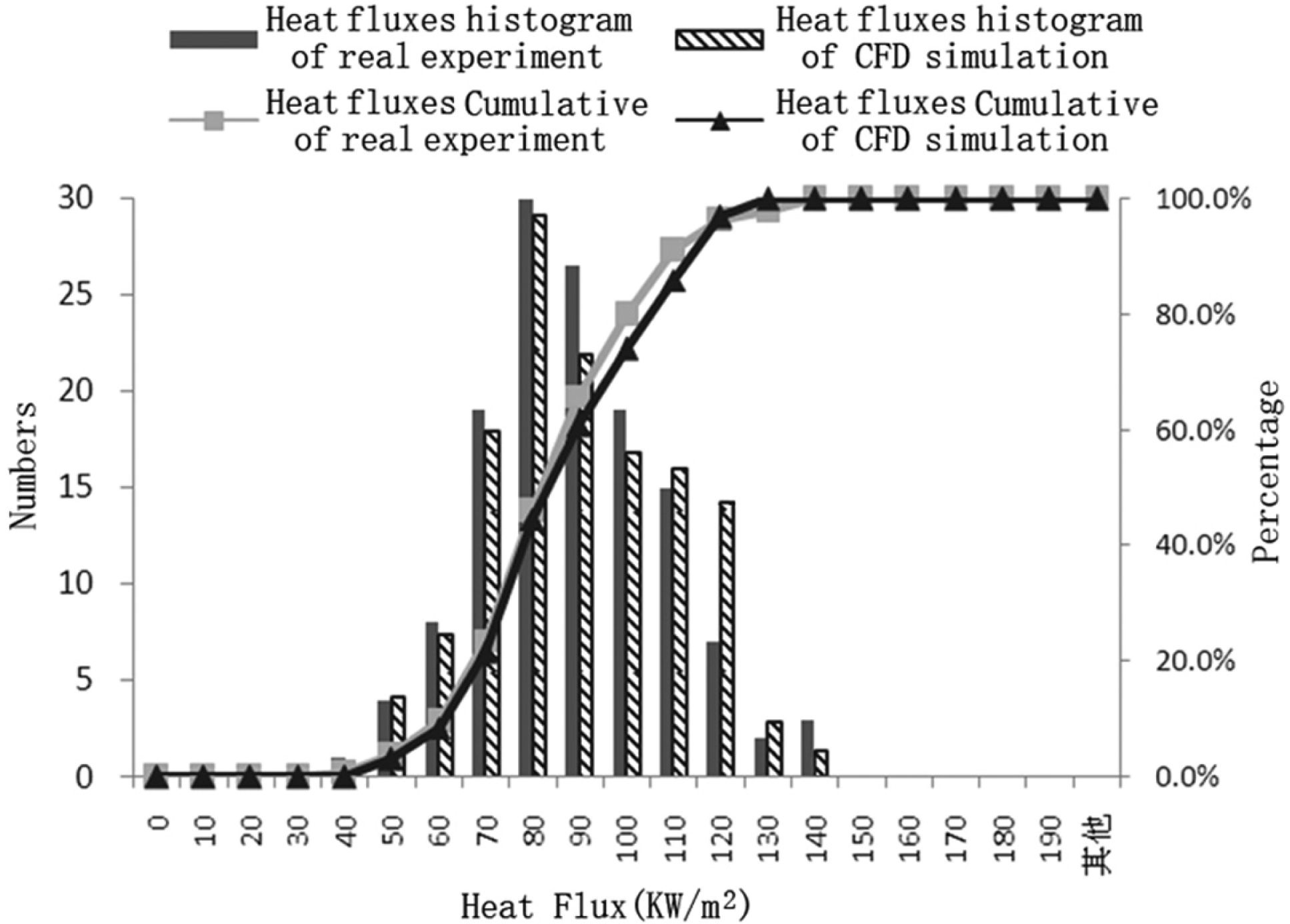
Comparisons of heat fluxes histogram of CFD simulation and those of actual manikin tests.
In the second stage, the heat flux histories’ comparison between the clothed manikin tests for three close-fitting garments and their CFD simulation is shown in Figure 8(b). The measured experimental data are the average of three clothed manikin tests. As a result of thermal protective effects of the Nomex IIIA garment, the surface heat flux of the manikin greatly decreases. The average heat flux on the manikin face at the end of 4-s fire exposure is about 40 kW/m2, which is on the same level of the heat flux measured by sensors in clothed manikin tests. The time-averaged heat flux of the two curves is similar. But the standard deviation of the simulated heat flux histories is 18.9 kW/m2, which is higher than that of the measured heat flux 12.5 kW/m2.
However, during the first 2 s after ignition, the average heat flux result of simulation is smaller than the measured value. This may be due to the porous media characteristics of garments. Under the propane jet combustion action, there will be low-speed porous flow through garments, 12 which increases heat transfer rate at the beginning of flash fire. But our model neglected the impact of the heat transfer caused by the porous flow. On the other hand, during the time of the second to 4th second after flaming, the heat flux result of simulation is larger than the experimental values. Considering Nomex IIIA fabric shrinkage usually occurs at about the second after fire ignition, 13 the reason should be that fabric shrinkage during exposure increased its compactness, reduced the permeability, 14 and attenuated the heat transfer caused by the porous flow in clothed manikin tests for close-fitting garment.
Figure 10 illustrates time variation of the heat flux on the garment surface of CFD simulation. It is noteworthy that after adding the garment, the average heat flux on the garment surface reaches only 75 kW/m2, which is 11% lower than the standard heat flux of the nude exposure. This is mainly attributable to the big difference of thermophysical properties between the fire proof garment itself and the manikin material, especially the thermal conductivity difference. Compared to the manikin body, the heat insulation of Nomex garment is much bigger, hindering the heat transfer from the fire to the body. However, the disturbance to the total heat flux caused by the presence of the garments had not received enough attention in previous researches.7,11,15 In most of the previous numerical simulation of clothed manikin tests, the value of 84 kW/m2 measured in the nude manikin experiment was used directly as the incident heat flux on the outer surface of the garments. The simulation results clearly reveal that this will bring errors.
Histories of garment surface heat flux of CFD simulation.
In order to further verify the exactness of the CFD simulation results, the comparison of temperature distribution over the manikin body between the manikin tests and their simulations at the end of 4-s fire exposure is made, as shown in Figure 11. It is shown that, as a whole, the simulated temperature distribution on the manikin surface is in accordance with that measured by 135 sensors for both naked manikin tests and clothed manikin tests. The surface temperature of the back is higher than the chest when wearing a close-fitting garment, which is in accordance with the experimental results.
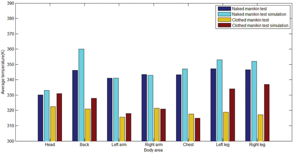
Comparison of temperature distribution over the manikin body between the manikin tests and their simulations at the end of 4-s fire exposure.
By comparison, an interesting phenomenon is found that the temperature of the head was the lowest in naked manikin experiment, but in clothed manikin test for close-fitting garment, the head temperature is higher than the temperature of the chest, back, and arms. This is due to the heat insulation effect of fire proof garment which slows the heat transfer in the direction perpendicular to the garments and strengthens the heat transfer in the upward direction along the garment surface. For clothed flame manikin tests, the simulated temperature of the legs is higher than the temperature of legs measured by sensors. This is due to the fact that the Nomex IIIA cover all shrinks significantly in areas around the legs of the manikin during a 4-s exposure to 84 kW/m2, thereby reducing the insulating air layer by a large amount which is compatible with Song’s 16 research.
Temperature results of transient CFD simulation of the clothed manikin test
The temperature filed in combustion chamber, including the temperature distribution of the garment surface, is obtained by CFD simulation. According to the propane adiabatic temperature of 2300 K, the simulated flame temperature, up to 2200 K, is reasonable. The front views of the temperature distribution of the garment and the manikin body at the moment of 4 s after ignition are shown in Figure 12(a) and (b), respectively. The highest temperature of the garment surface is up to 700 K, and the highest temperature of the manikin surface covered by garment is only 330 K. The right arm’s temperature is slightly higher than the left arm’s being in agreement with experiment results. Although the body is symmetrical, the layout of 12 burners is nearly symmetric, the body surface temperature field is not completely symmetrical because of the violently unsteady flame.
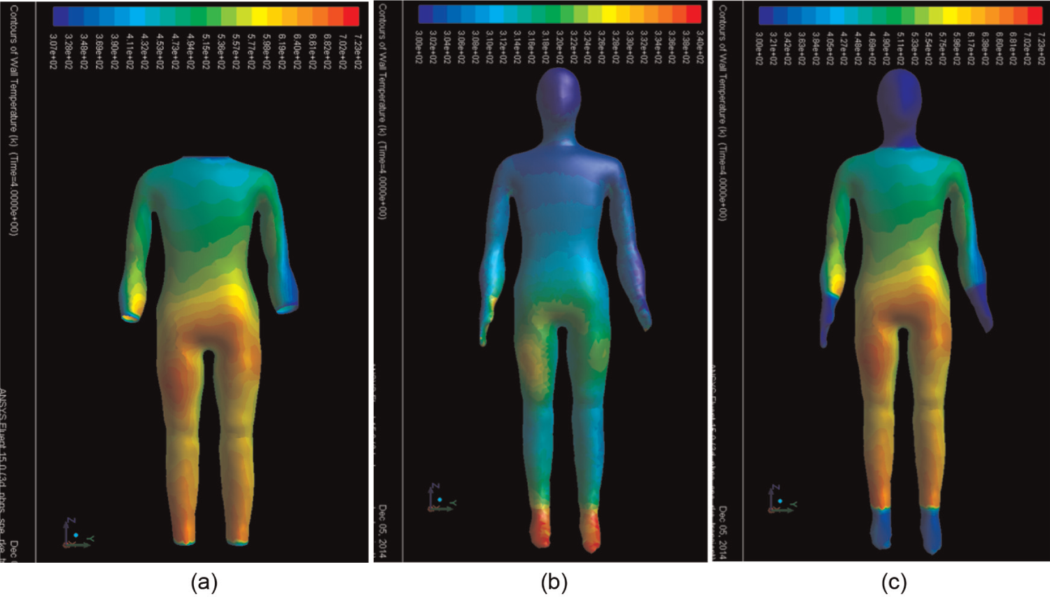
(a) The garment surface temperature distribution, (b) the manikin surface temperature distribution, and (c) the overall temperature distribution at the end of 4-s fire exposure.
Conclusion
In this article, we have designed close-fitting clothed manikin tests based on Donghua flame manikin system and have numerically simulated the clothed manikin tests for one-layer close-fitting garments made from Nomex IIIA by means of CFD techniques. We have developed a method of geometrical modeling of the manikin with close-fitting garment and the chamber using a 3D body scanner, Geomagic studio and Gambit software. The temperature field on the outside surface of the garment is obtained via the full-scale 3D transient CFD simulation of the clothed manikin test, which can help to discover the heat transfer characteristics of the garment itself during the flash fire exposure. The prediction results have been validated by comparing with the measured data of close-fitting clothed manikin tests. It can be concluded that the numerical model reasonably simulated the manikin test for a single-layer close-fitting garment.
Furthermore, the effect of adding garments on the incident heat flux was investigated. In the same fire environment, the average incident heat flux on the outer surface of the garment is not 84 kW/m2, which is used in most of previous numerical simulations, but significantly lower than this value. This can help to determine the more correct boundary conditions in the further numerical simulation researches.
Footnotes
Declaration of conflicting interests
The author(s) declared no potential conflicts of interest with respect to the research, authorship, and/or publication of this article.
Funding
This work was financially supported by the National Nature Science Foundation (51576038), the Fundamental Research Funds for the Central Universities, and the Open Funding Project of National Key Laboratory of Human Factors Engineering.