
Abstract
The fire resistance of composite slabs with steel decking, in Europe, is usually defined using simple calculation models provided by the Eurocode EN 1994-1-2. For assessing the methodology of these simple calculation methods, a new advanced calculation method is presented, using the software ANSYS. The numerical model is first validated with experimental data reported on bibliography and then a parametric analysis is conducted to better understand the effect of the load level on the composite structure under fire. The validation of the simulations consisted of three different models: the first model considers perfect contact between the steel deck and the concrete topping, and the two following models consider the existence of an air gap between these materials, acting as a thermal resistance on the temperature field through the thickness of the slab. The numerical results show good approximation to the experimental results, mainly when using the non-perfect contact model, reaching 3.88% and 16.91% of difference with respect to the insulation and load-bearing criteria, respectively. Based on the validation models, a parametric study is presented, modifying the load level from 10% up to 75%. New simple calculation models are presented to define the fire resistance of composite slabs, considering the load level, and the debonding effect between the concrete and the steel deck.
Introduction
Since 1980, a significant increase in composite slabs with steel decking has been recorded in every type of buildings. 1 A composite slab consists of cold-formed profiled steel deck which acts as a permanent formwork to the concrete topping. Normally, this composite solution requires the addition of other components such as steel rebars (placed within the ribs) for positive bending and steel mesh near the top for negative bending, also preventing cracks in concrete (Figure 1). The composite action between the concrete and the steel deck is generally achieved by indentations or embossments in the steel deck. Due to the external reinforcement provided by the steel deck, composite slabs generally require less additional reinforcement and less concrete as well, resulting in slender slabs. In addition, the reduction of the construction time, reduction or even elimination of struts and the simplicity of installation are other advantages of composite slabs in comparison to conventional flat concrete slabs.
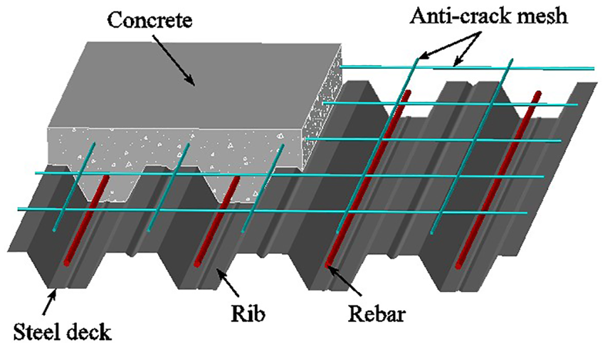
Typical layout of a composite slab with the trapezoidal steel deck.
The overall depth usually varies between 100 and 170 mm. Several types of steel deck are marketed in Europe, with thickness varying between 0.70 and 1.25 mm, usually made from galvanized steel to increase durability by preventing corrosion. 2
Composite slabs must meet fire-safety requirements in accordance with standards and regulations. Generally, standard fire tests using the standard fire curve ISO 834 3 are used to determine the fire rating of this structural element, accounting for load-bearing (R), integrity (E) and insulation (I).
The insulation (I) assessment shall be made on the basis of the average temperature rise on the unexposed surface limited to 140°C above the initial average temperature, or made on the basis of the maximum temperature rise at any point of the unexposed surface, limited to 180°C above the initial average temperature. The load-bearing resistance (R) assessment shall be made on the basis of limiting maximum vertical displacement (D = L2/400d (mm)) or limiting maximum rate of vertical displacement (dD/dt = L2/9000d (mm/min)), L being the clear span of the testing specimen in millimetres and d is the distance from the extreme fibre of the cold design compression zone to the extreme fibre of the cold design tensile zone of the structural cross section in millimetres. The integrity (E) is the capacity to withstand fire in one side of the slab, 4 and according to the Eurocode EN 1994-1-2, 5 it is always satisfied while steel deck works as a membrane to the structure.
Eurocode EN 1994-1-2 also considers that, if evaluated under the load-bearing criterion (R), the fulfilment of EN 1994-1-16 design requirements guarantee 30 min of fire resistance.
In practice, rebars should be applied to composite slabs with steel deck in cases when the required fire resistance time is higher than 30 min. When these elements are submitted to longer periods of fire exposure, the contribution of the steel deck to the load-bearing resistance decreases considerably, being part of this capacity transferred to the rebars.
The profile geometry of the steel deck and the existence of the ribs in composite slabs create an orthotropic profile, resulting in complex thermal gradients, hence presenting challenges in numerical modelling. 7 In recent years, several studies have been conducted in order to investigate the fire behaviour of these structural elements.
Based on the experimental results from different European laboratories, in 1983, the European Convention for Constructional Steelwork (ECCS) published the first recommendations applied to the design of composite slabs with profiled steel deck under standard fire conditions, 8 introducing simple calculation rules. Conservative assumptions were adopted, resulting in uneconomical solutions.
Between 1989 and 1993, more than 30 full-scale fire resistance tests were carried out on a wide range of structural assemblies in the United Kingdom, demanded by the Steel Construction Institute, and these were summarized in multiple publications. 9 One of these was made by Thomson et al. 10 concerning standard fire tests on composite steel and concrete slabs, using two types of slabs and two kinds of concretes (normal weight concrete (NWC) and lightweight concrete (LWC)), supported by thermal insulated steel beams capable of resisting heat effect for 90 min. The test was performed for 120 min, the furnace temperature was controlled to follow ISO 834 curve and the temperatures on slabs and beams profile section were measured.
Based on the ECCS publication, in 1990 the first draft of Eurocode 4 – Part 1–2 – included new design rules to composite slabs. This document was then revised and a final version was published only in 1993. 11
Hamerlinck 2 conducted a numerical and experimental study regarding the thermal and mechanical behaviours of reinforced composite slabs under fire conditions. Both numerical models were experimentally validated with loaded and unloaded tests. The testing programme took into consideration the most important parameters for fire resistance and a new computer programme was developed, enabling simulations at low computational cost (low time processing). It was concluded that the developed two-dimensional (2D) model provided satisfactory results, although not including three-dimensional (3D) thermal effects.
Both 12 carried out an investigation with the main objective of introducing easy-to-handle calculation rules as well as providing more insights on the fire behaviour and failure modes mainly of continuous composite slabs. The numerical models were validated against the results of experimental tests performed by the author and other researchers. A parametric study was performed, and simple calculation rules were derived from the results. The thermal model was able to describe the 2D and 3D heat flow in composite slabs during fire exposure, being used to improve the Eurocode EN 1994-1-25 simple calculation model to define the fire resistance of composite slabs (R) criterion, published in 2005.
Bailey and Guo 13 investigated the thermal and mechanical responses of composite slabs using trapezoidal steel decks, during heating and cooling stages, intending to provide data to future research on thermal resistance and numerical modelling. In their fire tests, seven different conditions were analysed, using the same structure but varying fire conditions, loading rates and cooling conditions. Different fire scenarios were used to simulate a natural fire, and the results showed that the process of heating and cooling the structure using different fire scenarios, in different loading conditions, influences not only the temperature distribution within the slab but also the residual deflections registered at the end of the tests.
Full-scale fire tests were carried out by Li et al. 14 on composite slabs with profiled steel deck. The investigation aimed to study the influence of the boundary conditions, reinforcement location, slab layout as well as the effect of unprotected secondary beams on tensile membrane action. A comparison between experimental results and Eurocode 4 provisions showed that the simplified calculation method for fire resistance results in conservative assumptions.
Piloto et al. 15 proposed new advanced 3D calculation models capable of simulating 3D composite slabs under fire situations using software ANSYS. The models were validated with experimental data from Hamerlinck 2 and Lim et al., 16 and for the first time the debonding effect of steel deck from concrete topping was introduced into the thermal models. Solid finite elements were used to simulate the air gap between solid elements used for concrete and shell elements used for steel deck. This method proved to be precise but requires longer times of simulation and the compatibility with the mechanical model is not easily achieved.
The importance of developing numerical simulation of composite slabs under fire situations can be demonstrated by the elevated costs of the experimental tests and the time consumed for this task. Simulation also provides more data, depending on the model complexity, being capable of simulating complex phenomena, such as the debonding of materials as proposed by Piloto et al. 15
In this work, the fire resistance of the composite slabs is defined with respect to standard fire ISO 834 exposure given below. The scope of this investigation concerns the fire resistance of composite slabs for R and I criteria. Numerical simulations with finite elements were developed, using ANSYS, to find out the thermal and mechanical effects of standard fire exposure, for the condition of perfect contact and non-perfect contact between steel deck and concrete topping, and the results of the numerical simulation are compared with experimental results from Hamerlinck. 2
The non-perfect contact models were developed using shell finite elements to simulate an air gap between concrete and steel deck. This thermal air gap model differs from the previously developed model by Piloto et al. 15 This new shell finite element model provides faster simulation and improves the compatibility with the mechanical model. This new interface layer is then removed, but the thermal loads are kept, keeping the effect of the thermal resistance defined by the air gap.
Two parametric studies are also presented, based on the model defined by Hamerlinck, 2 to include the effect of the load level on the fire resistance evaluated under the load-bearing (R) criterion, 17 considering perfect contact and also the non-perfect contact between the steel deck and the concrete topping.
Based on the parametric studies, new simplified calculation models are proposed to define the fire resistance of composite slabs with steel decking, depending on the load level.
Eurocode 4: fire resistance of composite slabs
In this section, the simplified method is presented to determine the fire rating of structural element, accounting for insulation (I) and load-bearing (R).
Fire resistance for insulation (I)
A simplified method is presented in the Annex D of EN 1994-1-25 for the estimation of the fire resistance of unprotected composite slabs subjected to fire exposure, using the standard fire curve ISO 834. The analytical expressions presented in the current version of this standard are based on the research conducted by Both 12 . During the last few years, no revisions were made to these methods. 7 The fire resistance (I) with respect to thermal insulation criterion shall be determined according to equation (1)

The rib geometry factor (A/Lr) of the composite slab shall be calculated as follows
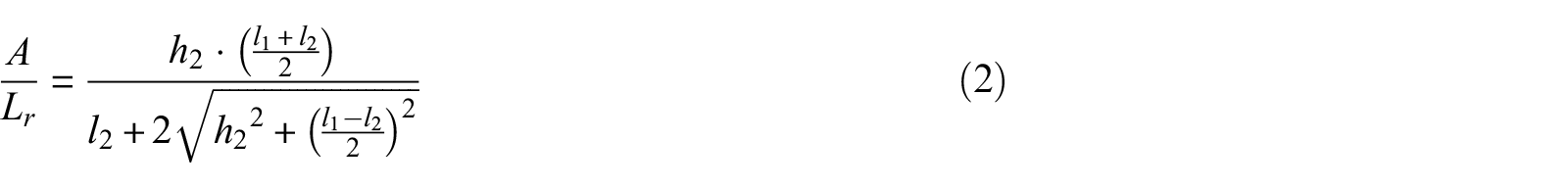
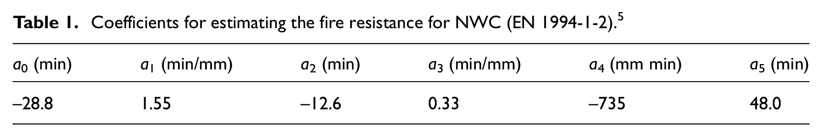
In addition to the geometric parameters of the composite slab, represented in Figure 2, the fire resistance (I) also depends on partial factors (ai). Table 1 presents these factors for slabs with NWC.
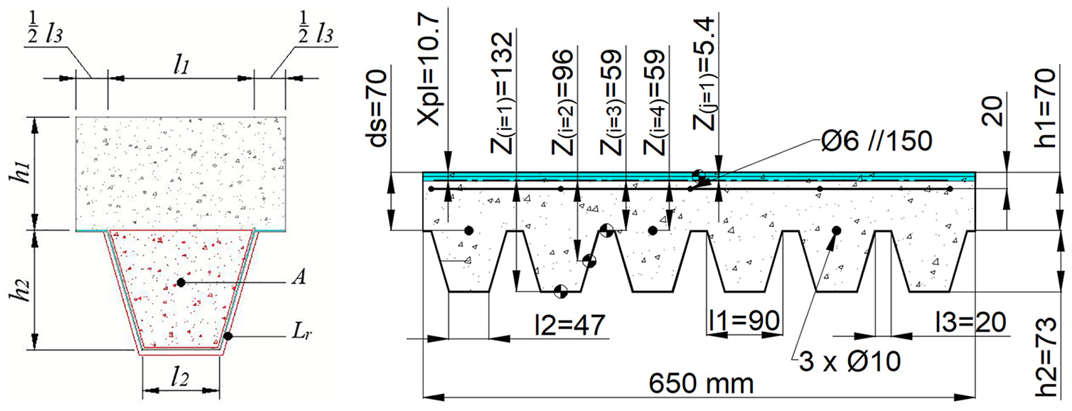
Model for the composite slab with steel deck.
Coefficients for estimating the fire resistance for NWC (EN 1994-1-2). 5
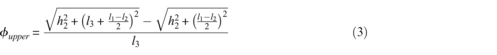
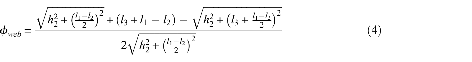
The view factor (ϕupper) of the upper flange, specified in equation (1), quantifies the geometric relation between the surface emitting radiation and the surface receiving, which depends on each surface area and orientation, as well as the distance between them. 18 The view factor at the lower flange of the composite slab is considered as ϕlower = 1. The view factor of the web ϕweb and that of the upper flange ϕupper of the steel deck are smaller than one, due to the obstruction caused by the ribs of the steel deck. These values can be calculated by Hottel’s crossed-string method, using equations (3) and (4)
Load-bearing resistance (R)
Following the calculation rules of mechanical behaviour of composite elements made of steel and concrete, the Eurocode 1994-1-25 provides general rules on the determination of composite steel-concrete slab load capacity. Based on a global plastic analysis, the design for bending resistance may be determined using equation (5)
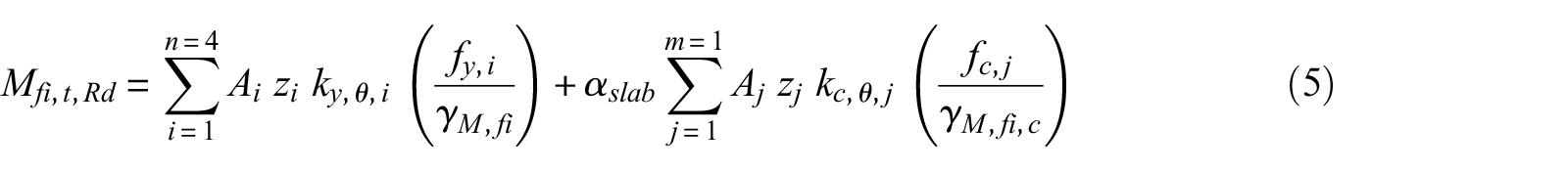
The coordinates zi and zj are the distances of the steel components and concrete, between the geometric centre of the components and the neutral axis of the slab, under fire conditions (Figure 2). Coefficients ky,θ,i and kc,θ,j concern the reduction coefficients for the yielding stress of steel and compressive strength of concrete, affected by the temperature of each component, being defined by standards for steel 19 and concrete. 20 ky,θ,i has different values, according to the type of steel (cold-formed carbon steel for the design of class 4 sections at elevated temperatures 5 and cold-formed carbon steel for rebars 19 ). The model assumes no reduction for concrete.
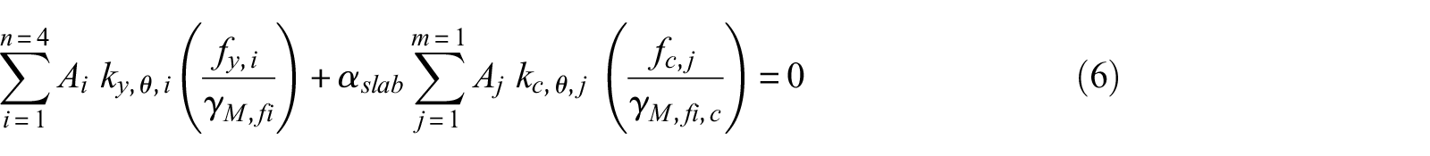
The neutral axis under fire conditions can be defined by the equilibrium of equation (6). 5 This axis modifies its position, moving from the hot region to the cold region, see Figure 2 for the position after 90 min of fire exposure
The fire-safety verification shall be made comparing the maximum bending resistance moment with the effect of the applied bending moment. In this study, for the case of a simply supported slab with a distributed load (q), the effect of the applied bending moment may be calculated using equation (7)

Numerical simulations
The methodology used to model and solve the thermal and mechanical behaviours on the composite slab is presented. Therefore, a brief description of the finite elements, thermal and mechanical properties of materials, boundary conditions and convergence criterion are given for both solution models.
An experimental test conducted by Hamerlinck 2 (test number 2) was selected to perform numerical validation for both mechanical and thermal models. The slab was composed of a trapezoidal steel deck, PRINS PSV 73 and a 70-mm thick concrete topping using NWC. The simply supported slab was submitted to the ISO 834 standard fire. The profile of the composite slab is shown in Figure 2. The NWC and the measured moisture content of 3.5% were used for the composite slab.
Thermal model
The composite slab is meshed in order to solve a non-linear transient thermal analysis, using 3D finite elements. The finite element method (FEM) requires the solution of equation (8) in the domain and the definition of the boundary conditions according to equation (9) in the exposed and unexposed sides of the slab


where T represents the temperature of each material; ρ(T) is the specific mass; Cp(T) is the specific heat; λ(T) is the thermal conductivity and αc is the convection coefficient. Tg represents the gas temperature of the fire compartment, using the standard fire ISO 834 applied on the bottom part of the slab; ϕ is the view factor (see the previous section); εm is the emissivity of each material; εf represents the emissivity of the fire and σ represents the Stefan–Boltzmann constant (5.67 × 10⁻⁸ W m−2 K−4).
The FEM is applied to solve numerically the heat transfer equation. For an arbitrary composite slab with the trapezoidal steel deck, the respective 3D mesh is presented in Figure 3.
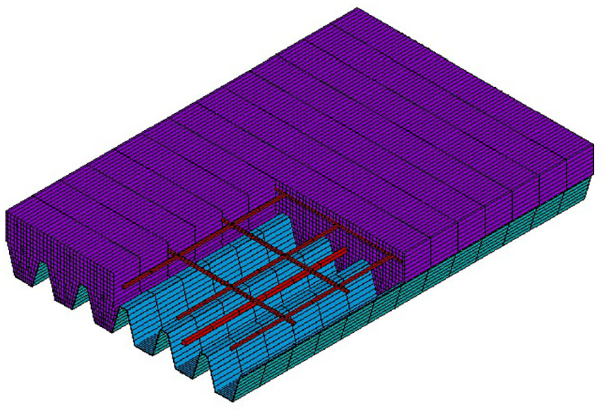
Finite element mesh of a composite slab with the trapezoidal steel deck.
The 3D model of the composite slab considers perfect contact between materials, namely, the concrete topping, the steel deck, the steel rebars and the steel mesh. Two alternative thermal models consider the air gap effect with a constant thickness (0.5 and 1.0 mm, each), being included between the steel deck and the concrete topping in order to simulate debonding effects.
The following three different finite elements are used: SHELL131, SOLID70 and LINK33. Compatibility between the nodal shell temperature and the nodal solid temperature is guaranteed using the paint option for SHELL131. The shell element is used to model the steel deck of the composite slab, and in the alternative models, a layer is added to this element to simulate the air gap that takes place between the steel deck and the concrete topping. The SOLID70 element is used to model the concrete topping, and the LINK33 element is used to model the mesh and the rebars.
The thermal properties of the materials are temperature dependent and vary according to the standards used for composite structures.5,19,20 The thermal properties of steel and concrete are presented in Figures 4 and 5, respectively. The upper limit for the conductivity was selected for the numerical simulations. The specific heat of concrete presents a peak value related to 3% of moisture content of concrete weight.
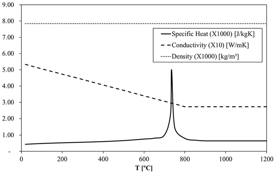
Thermal properties of carbon steel.
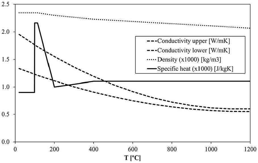
Thermal properties of concrete.
The thermal properties of air are depicted in Figure 6, based on values provided by Çengel and Ghajar. 21 These properties are also temperature dependent and were used in the air gap to simulate the effects of debonding between the steel deck and the bottom surface of the concrete. This model only considers the heat flow by conduction in the air gap, due to the very small air gap thickness.
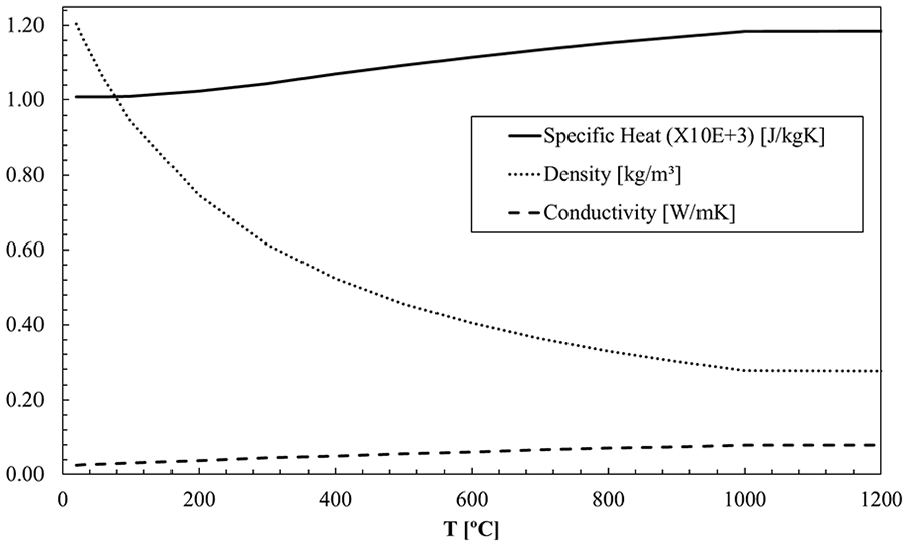
Thermal properties of air.
All the nodes of the numerical model are set with an initial condition for a temperature of 20°C. The exposed side of the slab was submitted to a heat flux by convection and radiation, see equation (9), using a convection coefficient of 25 W m−2 k−1, using different values for view factors and a bulk temperature following the standard fire. The unexposed side is subjected to a convective heat flux (which includes the radiation heat flux effect), using a convection coefficient of 9 W m−2 k−1 and a constant bulk temperature of 20°C (Figure 7).

Representation of the applied boundary conditions.
The heat flow condition was selected for the convergence criterion, using a tolerance value of 10−3 and a minimum reference value of 10−6.
Mechanical model
The mechanical simulation for the fire behaviour of the composite slabs is also presented. The model is validated using the experimental results from Hamerlinck. 2 The displacement and the rate of displacement are compared with the experimental results and compared with the criterion used for fire rating given by EN 1363-1. 17
The solution method is incremental in time and iterative, due to the non-linear behaviour of material and geometry. Here, one can assume the existence of an external load {F} (live and dead load), which must be in equilibrium with stress field in each material. The final version of the equilibrium equation may be expressed in every Cartesian coordinate, according to equation (10)

The external load {F} is assumed to be constant under fire conditions. The load-bearing capacity was determined for room temperature, using equation (11) for sagging moment resistance and assuming the neutral axis to be located above the steel deck. Mp,Rd represents the plastic bending resistance, Np,pl is the plastic tensile force for the effective section of the plate, Ns, pl represents the plastic tensile force for rebars, dp is the centroidal position for the plate measured from the top of the cross-section, xpl represents the position for the plastic neutral axis measured from the top and ds represents the position of the rebars measured from the top

The mechanical load is distributed over four lines of nodal loads (FY), with a spacing of 800 mm. This load represents the live load (used as parameter). The dead load is included by means of inertial effect (2800 N/m2). The composite slab is simply supported (restraining the displacements in vertical and out-of-plane directions at the left support and restraining all displacements in the right support). The lines of nodal forces were applied in accordance to the experimental setup (Figure 8).
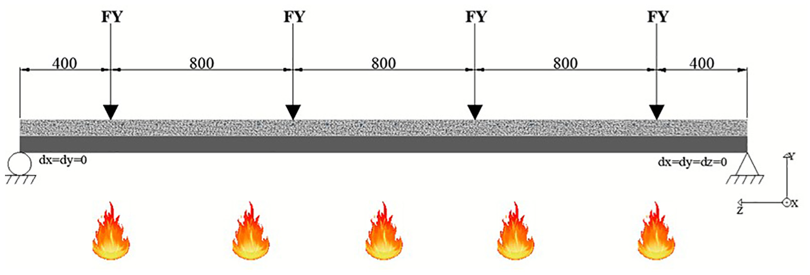
Representation of the mechanical model.
The thermal load effect introduces the incremental time effect, using different files with the corresponding temperature field for each time step.
The finite element model uses a full 3D finite element mesh, by switching the thermal SOLID70, SHELL131 and LINK33 finite element to the equivalent mechanical finite element SOLID185, SHELL181 and LINK180 (Figure 9).
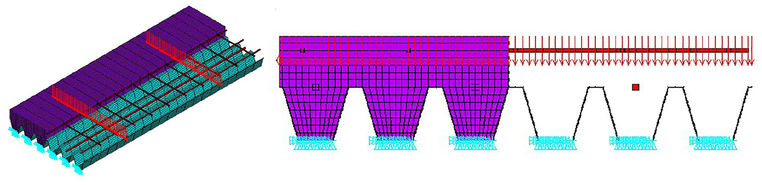
The finite element mechanical model.
The mechanical model was created based on the thermal model, modifying the thermal finite elements to compatible mechanical finite elements. The element SHELL181 was used to simulate the steel deck, the element SOLID185 was used to simulate the concrete topping and the rebars and steel mesh were simulated by the finite element LINK180.
Yet, on the alternative models, the upper layer of the shell finite elements, previously used to simulate the air gap between the steel deck and the concrete topping, is deleted, eliminating the direct effect of the air gap into the mechanical model behaviour.
The incremental solution, based on the Newton–Raphson method, is used, assuming the non-linear effect of geometry. The convergence criterion is defined by force and moment, using a tolerance value of 10−3 and a minimum reference value of 1. The elastic–plastic model was also assumed, considering the non-linear behaviour of the material properties. The thermal elongation for steel and concrete was also used, providing the capacity of simulating the thermal bowing effect due to the existence of a high thermal gradient on the slab thickness (Figure 10).
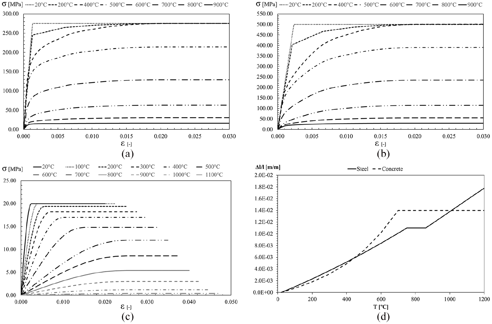
Mechanical properties for all materials: (a) mechanical properties of galvanized steel, (b) mechanical properties of reinforcement, (c) mechanical properties of concrete and (d) thermal elongations.
The mechanical properties of the materials are temperature dependent and vary according to the standards used for composite slabs, 5 steel structures 19 and concrete structures. 20 The concrete model also considers the partial confining effect by the steel deck, removing the negative tangent stiffness of the material behaviour, that is, presented in the traditional engineering curve for stress and strain, after reaching the maximum compressive strength, as suggested by EN 1992-1-2. 20 Similar modification was applied to both steel types, eliminating the negative tangent stiffness.
Results
The results of the 3D numerical simulations are presented in this section, resulting from the application of the preceding models. The thermal analysis presents the results obtained with perfect contact (PERF_C) and the models with an air gap of 0.5 mm (GAP_0.5) and 1.0 mm (GAP_1.0), between the steel deck and the concrete topping. These numerical results are compared with experimental results. A comparison of the fire resistance between the numerical, experimental and simple calculation method results is also presented.
A parametric analysis was developed to determine the effect of the live load. A new proposal is presented for the fire resistance (R), with respect to the load level.
Thermal simulation
Figure 11 illustrates the temperature development (numerical and experimental) at different points as well as the average and maximum temperatures at the unexposed side of the slab. It can be observed that the temperature development on the selected points at the exposed surface (point A and point H) is quite similar between the experimental and numerical models during the initial minutes of heating. Regarding the temperature development at points selected on the unexposed surface, the air gap models present better agreement with experimental results during all heating stages.
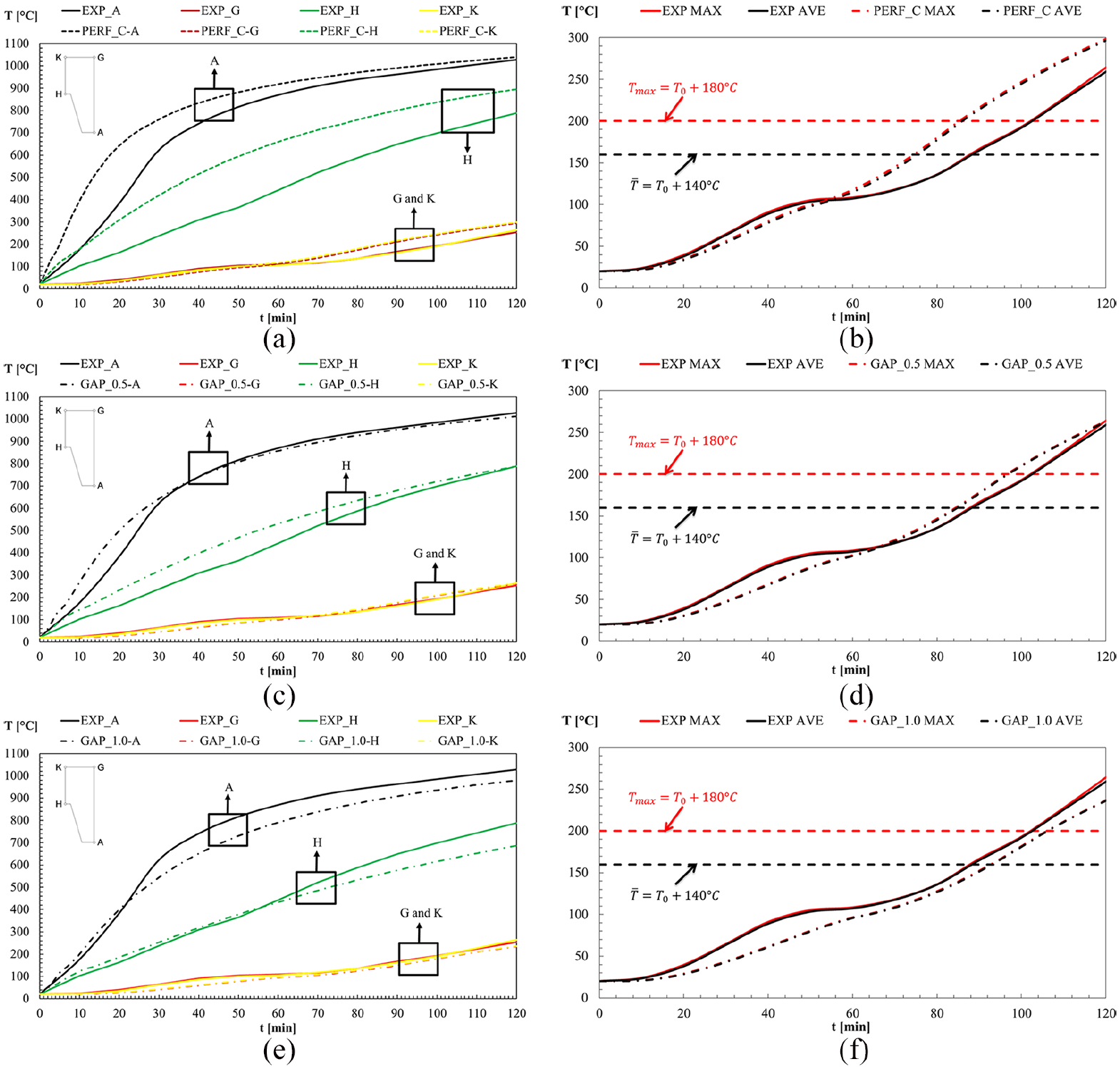
Comparison between numerical and experimental results: (a) selected points – perfect contact model, (b) unexposed side – perfect contact model, (c) selected points – 0.5-mm air gap model, (d) unexposed side – 0.5-mm air gap model, (e) selected points – 1.0-mm air gap model and (f) unexposed side – 1.0-mm air gap model.
Some important physical phenomena should be highlighted during the initial stages of heating. The existence of the moisture within the concrete is partially solved by the effect of the peak value used for the specific heat (Figure 5). The existence of the zinc layer on the exposed face of the steel deck may reduce the heating rate of the composite layer due to the melting of this material.22,23 Solutions to these physical phenomena are proposed by Hamerlinck, 2 assuming a variable emissivity value (ε) for the steel deck, changing from 0.1 to 0.7. The emissivity value has been considered constant during all the simulations (ε = 0.7), which may explain the temperature difference during the initial heating stages.
The experimental results show the existence of a plateau in the maximum and average temperature in the unexposed side of the slab, between 48 and 68 min, approximately. This can be explained by the evaporation effect and motion effect within the concrete. Higher values of moisture content result in longer periods for this plateau, which suggests that the moisture content of the experiment was higher than the value reported by the authors.
Table 2 presents the results obtained for the fire resistance (criterion ‘I’) of the slab with respect to the average temperature rise (tfiAve) and the maximum temperature rise (tfiMax) at the unexposed surface of the slab. The lowest value between the two criteria governs the fire resistance. The EN 1994-1-2 gives only one value, used to define the fire resistance
Fire resistance for insulation condition (I): numerical, experimental and analytical results.
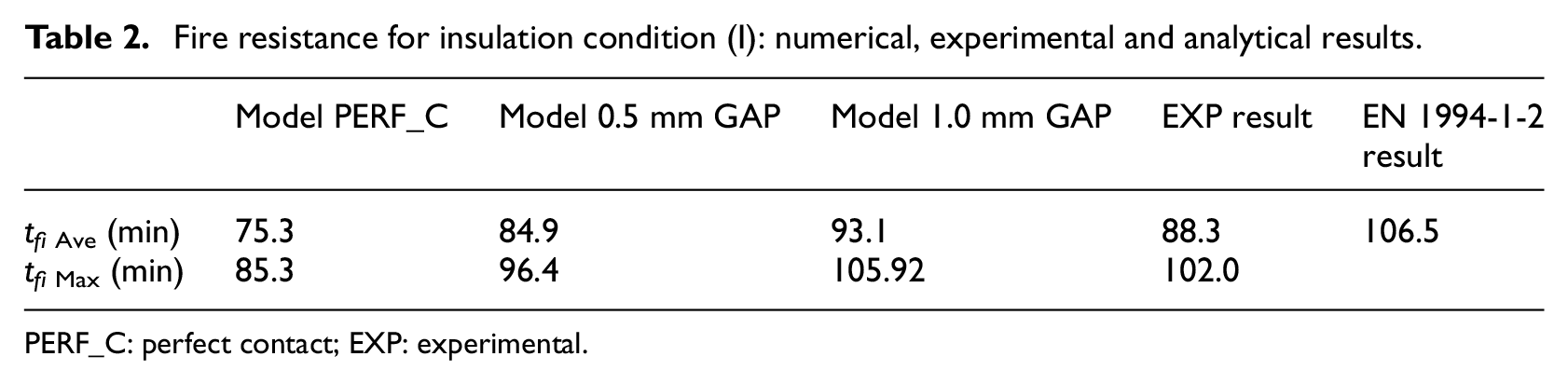
PERF_C: perfect contact; EXP: experimental.
Assuming the experimental result as a reference (88.3 min), it can be observed that the 0.5-mm air gap model underestimates the fire resistance, with a relative error of 3.88% and the 1.0-mm air gap model slightly overestimates the fire resistance, with a relative error of 5.41%. A bigger discrepancy was obtained using the perfect contact model, with a relative error of 14.72%. The EN 1994-1-2 proposal overestimates the fire resistance, providing an unsafe result with a relative error of 20.61%.
Mechanical simulation
The critical time was determined by the limiting conditions presented in EN 1363-1. 17 Figure 12 represents the comparison between the experimental results and the numerical results.
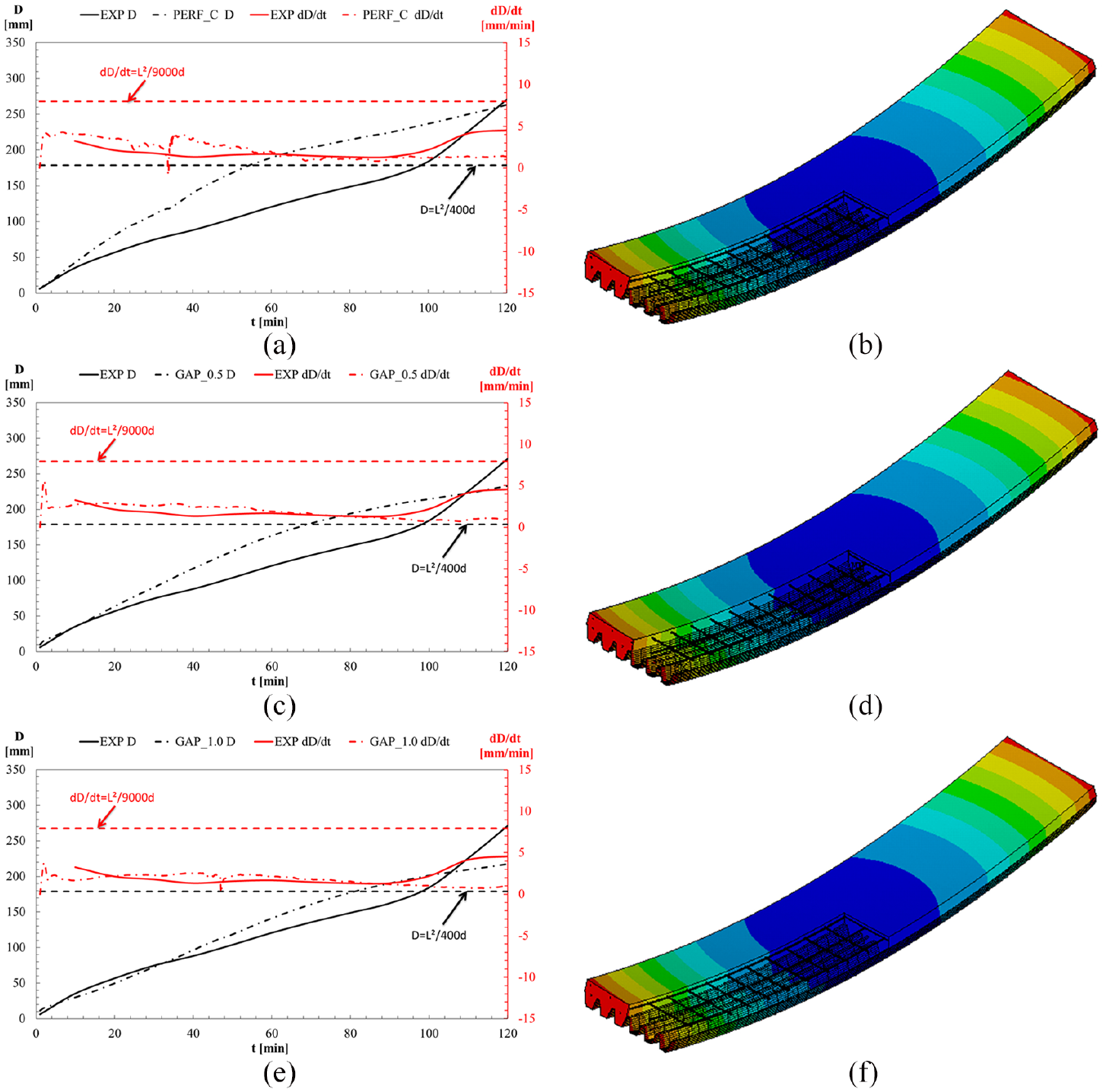
Analysis of the composite slabs with a live load of 2.7 kN/m2: (a) time history for displacement and rate of displacement for perfect contact model, (b) deformed structure of the perfect contact model after 2 h, (c) time history for displacement and rate of displacement for 0.5-mm air gap model, (d) deformed structure of the 0.5-mm air gap model after 2 h, (e) time history for displacement and rate of displacement for 1.0-mm air gap model and (f) deformed structure of the 1.0-mm air gap model after 2 h.
The vertical displacement of the slab increases with time and can be divided into three stages, as seen in the experimental results of Figure 12. In the initial stage, due to a high thermal gradient throughout the section of the slab, the curvature of the slab starts increasing rapidly and the deflection increases. In the second stage, the deflection rate decreases as the thermal bowing increases less, given a more homogenously distributed temperature in the cross section of the slab. Near the ultimate limit state, the deflection rate increases again due to the plastic material behaviour.
The model PERF_C presents higher temperature values for the materials and explains the higher values for the vertical displacement, in comparison with the GAP model. For both models, the displacement field is also represented in Figure 12.
As it can be seen, the numerical results show better approximation to the experimental results when using the air gap model. These models present lower temperatures through the thickness of the slab, which led to less impact of the temperature effect over the mechanical properties, and consequently, smaller deflections.
The difference between the results can also be related to several phenomena during the test (variation in the view factors, restrain effect in the supports, direction of the applied load during the test, among others).
The simplified calculation method, based on EN 1994-1-2, 5 overestimates the fire resistance when using equation (5). The fire resistance for this case is rated with R120, taking into consideration the existence of a bending moment of 4640.06 N m. The maximum sagging moment supported by this composite slab was determined for different fire ratings (Table 3).
Sagging moment capacity according to fire resistance class to normal weight concrete (EN 1994-1-2). 5
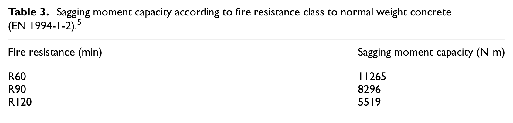
Table 4 presents the comparison for the mechanical models and experimental results concerning the load-bearing fire resistance (R).
Fire resistance for load-bearing condition (R): experimental, numerical and analytical results.
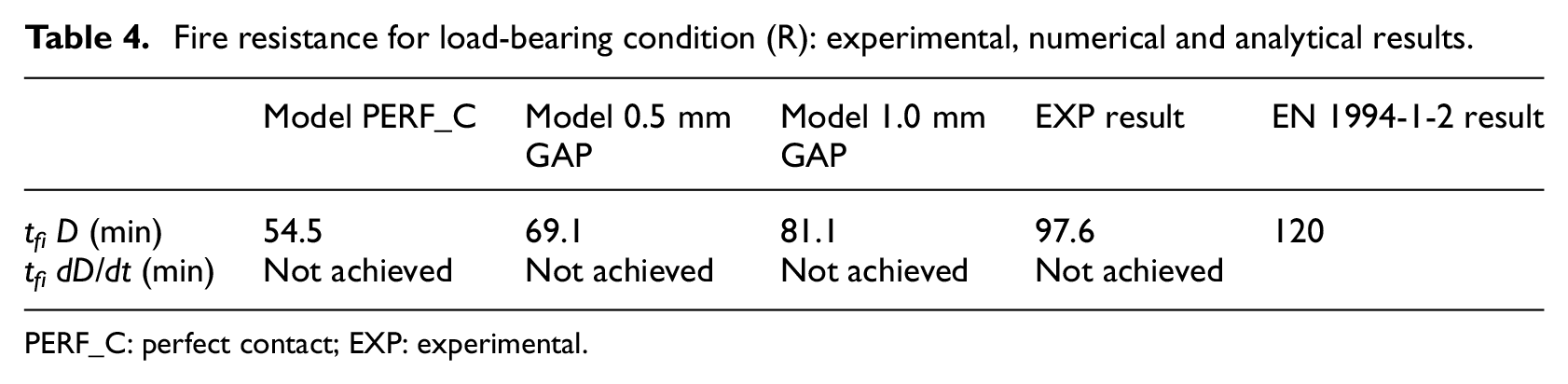
PERF_C: perfect contact; EXP: experimental.
All simulation results provided lower fire resistance in comparison to the experimental test. Taking results from experimental test as reference, the difference between them and the numerical results from perfect contact model (PERF_C) is 44%, the difference with the non-perfect contact model is 29% when using 0.5-mm air gap (GAP_0.5) and 17% when using 1.0-mm air gap model (GAP_1.0). The difference between simple calculation method and the experimental result is 23%. It is worth mentioning that the simple calculation method is only proposed for fixed fire rating periods of 60, 90 and 120 min.
Parametric analysis
Two parametric analyses were developed, one using the perfect contact model (PERF_C) and the other using the 1.0-mm air gap model (GAP_1.0), which was the model with best approximation to the experimental results. The load level, η, was determined by the ratio of the total load (live and dead) by the plastic load at room temperature, proposed by the Eurocode 1994-1-1. 6 The load level changed from 10% up to 75%, to predict the fire resistance of the composite slab not only under normal loading conditions on buildings but also under exceptional loading conditions. The fire resistance decreases with the increase in the load level (Figures 13 and 14). The critical temperatures of the steel components were determined based on the fire resistance criteria. These values also decrease with the load level. The fire resistance for load-bearing criterion was exclusively governed by the critical displacement value (D). It can be observed that for load levels above 40%, approximately, the simple calculation model from the Eurocode EN 1994-1-2 (Annex D) 5 underestimates the fire resistance of this structural element, leading to less economical solutions in fire design.
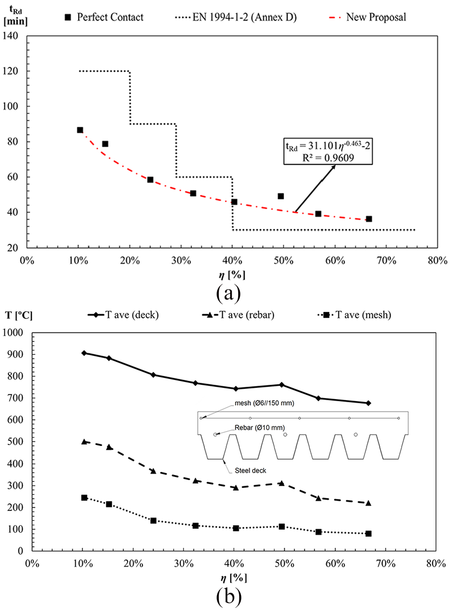
Fire resistance of the composite slab and critical temperature for the steel components – perfect contact model: (a) fire resistance and (b) critical temperature.
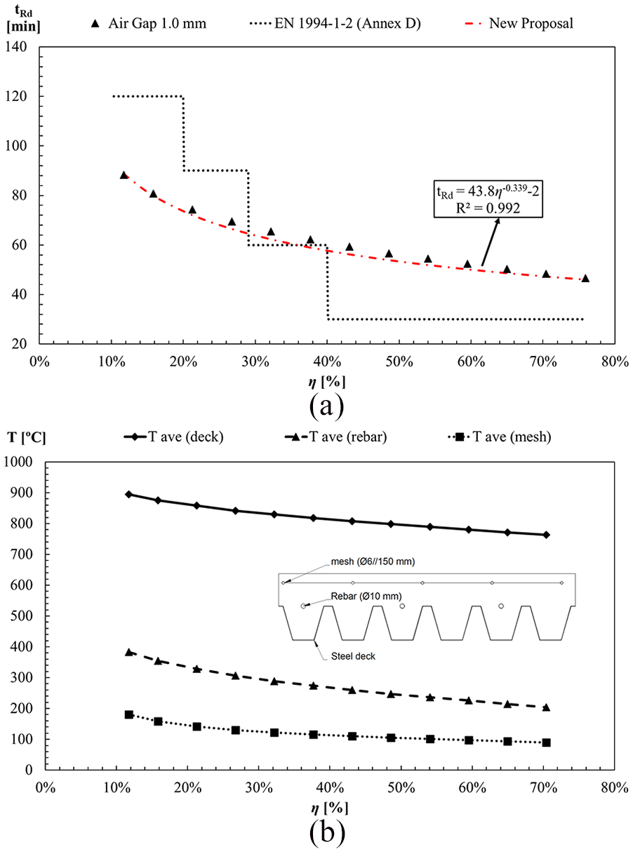
Fire resistance of the composite slab and critical temperature for the steel components – 1.0-mm air gap model: (a) fire resistance and (b) critical temperature.
Figure 13 shows the results of the parametric study conducted using the perfect contact model. The rate of displacement (dD/dt) did not reach the critical value for load level values below η = 40%. For higher load levels, the critical displacement rate becomes important, but never anticipates the time for the critical displacement. The thermal gradient can be easily determined for each load level, being approximately equal to 700°C/143 mm in the vertical direction. This value seems to be independent of the load level.
The fire resistance was approximated with the minimum safety level, considering the results of the new proposal below the line of the numerical results. The new formula is presented in equation (12)

This new formula, if evaluated at the load level applied on Hamerlinck experiment (η = 15%), indicates a fire resistance of 73 min, which indicates a safety level of 25%.
The results of the parametric study conducted using the 1.0-mm air gap model are shown in Figure 14. During the validation process, this model was the one with best approximation to the experimental results. Similar to the previous parametric study, and for every simulated loading condition, the critical displacement (D) was the criterion that governed the fire resistance of the composite slabs. The critical temperature of steel elements from the slab also decreases with the increase in the load level.
The numerical results were approximated with a curve capable of estimating the fire resistance of this structure, maintaining a minimum safety level. The new formula is presented in equation (13)

This new formula, if evaluated at the load level applied on Hamerlinck experiment (η = 15%), provides a fire resistance time of 81 min, which indicates a safety level of 17%.
The comparison between both proposals underlines the effect of the temperature field caused by the debonding between the concrete and the steel deck. When using the air gap model, lower temperatures are expected in all the components, as can be seen for the critical time of each simulation.
Conclusion
This study presents the description of the thermal and mechanical 3D finite element model and its validation against experimental results. The fire resistance according to the thermal insulation (I) and load-bearing (R) criteria was determined and compared to the experimental results and EN 1994-1-2. With the objective of simulating the debonding fire effect of the steel deck from concrete, an insulating layer (air gap) with a constant thickness was created between the concrete and steel deck. The effect of the thickness of this insulating layer was also tested using models with 0.5 and 1.0 mm of air gap.
Regarding the experimental results for the temperature development, a plateau at about 100°C (due to moisture evaporation) should be highlighted, resulting in a decrease in the rate of temperature increase. The numerical results do not present this pronounced plateau possibly because localized moisture concentrations in the test may be higher than the uniform moisture content introduced in the model (effective thermal property).
The fire resistance with respect to the insulation criterion was governed by the average temperature rise criterion for all the thermal models (PERF_C, GAP_0.5 and GAP_1.0) as well as for experimental test. The numerical models underestimate the fire resistance. In general, the results obtained with the air gap models presented better agreement with experimental results and satisfactorily simulated the debonding effect, mainly the model with 1.0 mm layer of air gap, reducing the temperature at the selected points.
The EN 1994-1-2 provisions for the fire resistance (I) and (R) are on the unsafe side, that is, the calculated fire resistance was greater than the fire resistance determined by experimental tests.
The fire resistance (R) determined by numerical simulation was always governed by the maximum displacement criterion. The numerical result underestimated the fire resistance (R) due to the higher temperature field achieved with these models.
The effect of the load level was also determined. The fire resistance (R) decreases with the load level and a new proposal is presented, based on the models with perfect contact and the models with 1.0-mm air gap, used to simulate the debonding of materials. The proposed calculation models provide a new and continuous fire resistance design formula, in comparison with the current version of Eurocode (step type). For small load levels, the fire resistance (R) determined by EN 1994-1-2 is higher than the fire resistance determined by the new formula. For higher load levels, the fire resistance determined by EN 1994-1-2 is smaller.
Future works should study the effect of other parameters over the fire resistance, such as the depth of the slab and the position of additional reinforcement.
Footnotes
Declaration of conflicting interests
The author(s) declared no potential conflicts of interest with respect to the research, authorship and/or publication of this article.
Funding
The author(s) received no financial support for the research, authorship and/or publication of this article.