
Abstract
We have designed a 2-spinnerette device that can directly electrospin nanofiber scaffolds containing a gradient in composition that can be used to engineer interfacial tissues such as ligament and tendon. Two types of nanofibers are simultaneously electrospun in an overlapping pattern to create a nonwoven mat of nanofibers containing a composition gradient. The approach is an advance over previous methods due to its versatility – gradients can be formed from any materials that can be electrospun. A dye was used to characterize the 2-spinnerette approach and applicability to tissue engineering was demonstrated by fabricating nanofibers with gradients in amorphous calcium phosphate nanoparticles (nACP). Adhesion and proliferation of osteogenic cells (MC3T3-E1 murine pre-osteoblasts) on gradients was enhanced on the regions of the gradients that contained higher nACP content yielding a graded osteoblast response. Since increases in soluble calcium and phosphate ions stimulate osteoblast function, we measured their release and observed significant release from nanofibers containing nACP. The nanofiber-nACP gradients fabricated herein can be applied to generate tissues with osteoblast gradients such as ligaments or tendons. In conclusion, these results introduce a versatile approach for fabricating nanofiber gradients that can have application for engineering graded tissues.
Introduction
Strategies for patterning cells and tissues are in high demand for replicating the hierarchical structures found in tissue and organs.1-4 Organs contain multiple tissues that interface with one another and can contain gradients in cells, growth factors, extracellular matrix proteins, or physical properties. Biomolecule gradients were first appreciated in development where gradients in morphogens are critical for pattern formation and generation of limbs. 1 In flies, localized secretion of the morphogen dpp establishes a spatial gradient of dpp concentration that induces a graded expression of the brk gene. This graded expression of brk leads to high omb and sal expression at low brk concentration, expression of only omb (no sal) at medium brk concentration, and no expression of either omb or sal at high brk concentration. The graded interplay between these fly genes leads to patterned development of wings for the fly. Avertebrate homologue of dpp is BMP-2 which is a key molecule for osteogenesis.
Another well-characterized example of a gradient in vivo is the byssal thread in mussels. 5 The byssal thread is a fibrous organ used by mussels to attach to rocks, which contains a gradient in mechanical properties. The mechanical gradient comes from a gradient in protein composition that exists along the thread. Expression of matrix proteins with different domains creates a gradient in stiffness that ranges from 50 MPa (soft) to 500 MPa (stiff). The soft end of the thread contains increased elastin-like domains which are soft, while the stiff end of the thread contains increased silk-like domains that are stiff. The mechanical gradient in the byssal thread mediates the stiffness mismatch between the mussel body and the stone to which the mussel must attach reducing contact deformation and interfacial stress.
Ligaments and tendons link soft and hard tissues and contain a gradation from calcified to noncalcified tissue.2,6 Specifically, ligaments have four regions as they transition to bone. The ligament itself contains fibroblasts in a matrix of collagens I and III. Next comes a noncalcified fibrocartilage region that contains fibrochondrocytes within collagens I and II. After that comes a mineralized fibrocartilage region that has a collagen X and hypertrophic chondrocytes. Finally, there is subchondral bone. This zonal organization of the interface contains a gradient in mechanical properties which enables efficient load transfer from bone to ligament.
Patterned scaffolds that can drive generation of patterned tissues can be used to tissue engineer these hierarchical structures.3,4 In order to advance methods for generating interface tissues, we have previously developed methods for fabricating 3D scaffold gradients for salt-leached scaffolds 7 and hydrogels. 4 Herein, we focus on nanofibers. Electrospun nanofiber scaffolds have shown promise because they mimic the nanotopography of native extracellular matrices.8,9 Collagen is the most abundant protein in mammals and it forms a matrix of nanofibers with a diameter of a few hundred nanometers.10,11 The majority of cells in vivo reside within this nanofibrous collagen matrix. Thus, we have developed a 2-spinnerette approach for fabricating nanofiber scaffolds with composition gradients.
Current approaches for fabricating nanofiber gradients require modification of nanofibers after electrospinning. The 2-spinnerette method described herein yields gradients directly. Previously, successive layers of different nanofibers were spun into a layered mat,12,13 assembly of nanofiber gradients were directed by a magnetic field 14 and nanofiber mats were differentially exposed to a reactive solution.15,16 The 2-spinnerette approach is versatile and can yield nanofiber gradients from any materials that can be electrospun including polymers, composites, nanoparticles, growth factors, peptides, natural proteins, or ceramic particles.
Herein, two spinnerettes were placed side-by-side todispense simultaneously two different types of nanofibers that lay down in an overlapping pattern to create a gradient in nanofiber composition. The device and gradient fabrication were characterized using dyesand absorbance measurements. To demonstrate the application of the nanofiber gradients, an orthopedic tissue engineering model was invoked using polymeric nanofibers with gradients in amorphous calcium phosphate nanoparticles (nACP).
Poly(ε-caprolactone) (PCL) was used as the polymer for the nanofibers since PCL scaffolds can support osteogenesis.17,18 Composition of nACP was varied in the nanofiber gradients since calcium phosphates are osteoconductive.13,15,17,19 The major inorganic component of bone is calcium phosphate (CaP) and bone tissue engineering scaffolds have used many different forms of CaP.20–25 Composites of polyamide and hydroxyapatite (HA) nanoparticles were osteoconductive in vivo. 22 Porous HA scaffolds laden with human bone marrow stromal cells also had excellent osteoconductivity in a 7-year clinical study of human long bone defects. 21 A calcium phosphate cement cleared for clinical use is a mixture of tetracalcium phosphate and dicalcium phosphate which can be fabricated into porous 3D tissue scaffolds. 24 Finally, a suspension of HA, tricalcium phosphate, and primary human bone marrow stromal cells can support ectopic osteogenesis when implanted subcutaneously in mice. 23 Calcium phosphate biomaterials can elicit their effects by releasing calcium ions which stimulate osteoblast proliferation through a calcium receptor or by releasing phosphate ions which stimulate osteoblast differentiation.26,27
Nanofibers with nACP gradients were fabricated and used to screen adhesion (1 d) and proliferation (7 d) of the MC3T3-E1 murine calvarial osteoblast cell line, a well-characterized in vitro model for osteoblasts. 28 The results show that the nACP-nanofiber gradients can induce a graded osteoblast response which can have application for engineering graded tissues such as ligament or tendon.
Materials and methods
Demonstration of nanofiber gradients by creation of a library Sudan red stained fibers
A new 2-spinnerette approach was developed that deposits two different polymer solutions into a nonwoven mat composed of a mix of two nanofiber types in the form of a gradient. The new method was characterized by fabricating gradients of Sudan IV red dye and measuring absorbance to determine composition. PCL (relative molecular mass 80,000 g/mol) was used to fabricate scaffold libraries using 10% (mass/volume, 1 g PCL in 10 mL solvent) solutions in 3:1 chloroform: methanol (volume ratio). One spinnerette spun PCL fibers (clear) while the second spinnerette spun PCL fibers with Sudan IV (0.03% mass/volume; red). Two beveled syringe tips (18 gauge, 10 cm) with bevels facing each other were used as spinnerettes. Spinnerettes were 2.5 cm apart and oriented vertically 17 cm above the target (aluminum foil, 32.5 cm × 33.5 cm). The spinnerettes were offset in the z-direction (vertical) so that thered spinnerette was 3 mm lower than the clear one. The flow rate was 2 mL/h per spinnerette (4 mL/h total) with voltage 16 kV (24°C, 50% relative humidity) for a1-h spin time. The ground was attached to the foil target. An insulated wire connected the two spinnerettes and was bared in the middle where it was connected to the positive lead from the power supply. Spinnerettes were mounted with plastics (no metal within 10 cm of the spinnerettes) since metals interfered with the electric field causing inconsistent gradients. The process repeatably yielded a gradient (17 cm × 6 cm). The nanofiber scaffold libraries were cut into sections (0.5 cm × 6 cm), sections were dissolved in solvent (3:1 chloroform:methanol) and dye absorbance was determined spectrophotometrically (plate-reader, 440 nm). Control nanofiber scaffolds of uniform composition of either pure ‘clear’ (PCL) or pure ‘red’ (PCL with red dye) were analyzed as controls. To generate control nanofiber mats, the 2-spinnerette system was used with the same solution in both syringes.
Preparation of nACP
Amorphous calcium nACP with Ca:P molar ratio of 1.5 were prepared by a spray-drying process. 29 Briefly, calcium carbonate and dicalcium phosphate were dissolved in acetic acid solution at a 1.5 Ca:P ratio. The solution was sprayed through a nozzle (SUC1120, PNR America) on a glass column. Filtered air was drawn from the top of the column, which removed volatile acid and water from the sprayed liquid generating fine particles suspended in the airflow, which were collected using an electrostatic precipitator. nACP crystallinity was assessed by powder X-ray diffraction (Rigaku DMAX 2200, 2θ uncertainty was 0.01°). nACP morphology was assessed by transmission electron microscopy (Philips EM-400T field emission gun TEM, accelerating voltage 120 kV) where nACP particles were dispersed in acetone by sonication and analyzed after deposition onto amorphous carbon-coated copper grids.
nACP-nanofiber gradients
Nanofiber scaffolds with gradients in nACP were fabricated. One syringe was loaded with PCL (10% mass/vol.; 1 g PCL + 10 mL of 3:1 chloroform: methanol), while the second syringe was loaded with a PCL/nACP solution (1 g PCL + 0.43 g nACP + 10 mL 3:1 chloroform: methanol). nACP gradients were fabricated as described above for Sudan red gradients. nACP gradients had dimensions of 22 cm × 6 cm, which was different from the Sudan red gradients which were 17 cm × 6 cm. The presence of nACP in the polymer solution during electrospinning affected nACP gradient fabrication making them 5 cm longer than Sudan red gradients. For characterization, gradients were cut into sections (0.5 cm × 6 cm, 5 mg) and nACP content was quantified by thermogravimetric analysis (TGA; 10°C/min, 30°C to 600°C, under nitrogen, TA Instruments Q500). The residual mass percent at 592°C was used as nACP composition. Control nanofiber scaffolds of uniform composition of PCL or PCL-nACP were prepared for some experiments using the 2-spinnerette system (same solution was loaded into both syringes). Nanofiber scaffold morphology was assessed by scanning electron microscopy (SEM) of sputter-coated (gold) specimens (15 kV, Hitachi S-4700-II FE-SEM).
Cell culture
For cell culture, scaffold libraries were cut into four gradient strips (1.5 cm × 22 cm), affixed 8 strips per dish (24.5 cm × 24.5 cm plastic dishes, nontissue culture treated) using silicone vacuum grease, sterilized with ethylene oxide, and degassed 2 d in a desiccator under vacuum. MC3T3-E1 murine pre-osteoblasts (Riken Cell Bank) were cultured in α-modification of Eagle’s minimum essential medium (α-MEM, Cambrex Bio Science) supplemented with 10% fetal bovine serum (Gibco) and 0.060 mg/mL kanamycin sulfate (Sigma).28,30 The medium was changed twice weekly and cultures were passaged with 2.5 g/L trypsin (0.25% mass fraction) containing 1 mmol/L ethylenedinitrilotetraacetic acid (EDTA; Gibco). Cells passaged four times after receipt from Riken and at 80% confluency were used for all experiments. Seven million cells in 175 mL medium were seeded into each dish (12,000 cells/cm2), left undisturbed for 1 h to allow cell attachment, and moved to the incubator for 1 d or 7 d culture (medium change at 3 d).
Cell assays
One qualitative assay (imaging by fluorescence microscopy) and one quantitative assay (Picogreen DNA) were used to assess osteoblast adhesion and proliferation on nanofiber gradients. A total of 8 PCL-nACP gradient strips (1.5 cm × 22 cm) were used for the cell culture experiments: four of each for 1 d and 7 d. After cell culture and at appropriate time points (1 d or 7 d), each strip was cut into 14 sections for cell assays. The two end pieces were discarded, six sections were used for fluorescence microscopy (Sytox green), and six were used for Picogreen DNA assay. For fluorescence imaging, sections were fixed for 5 min (0.5% mass fraction Triton X-100, 4% mass fraction paraformaldehyde, 5% mass fraction sucrose, 1 mmol/L CaCl2, 2 mmol/L MgCl2 in phosphate buffered saline (PBS), pH 7.4), postfixed for 20 min (same as fix but without Triton X-100), blocked for 1 h (1% mass fraction bovine serum albumin), and stained for 1 h in PBS containing 5 µmol/L Sytox green (green nuclei; Invitrogen). Wet scaffolds were imaged using inverted epifluorescence microscopy. For SEM of cells, cells cultured for 1 d on scaffolds were rinsed with saline, fixed with 1% glutaraldehyde, subjected to graded alcohol dehydrations, rinsed with hexamethyldisilazane, sputter coated with gold, and imaged (15 kV, Hitachi S-4700-II FE-SEM).
For Picogreen DNA assay, scaffold sections were incubated overnight with lysis buffer (1 mL, 0.2 mg/mL Proteinase K (19 Units/mg; Sigma), 0.2 mg/mL sodium dodecyl sulfate (0.02 % mass/vol) in PBS) at 37°C. One mL of the lysates was transferred to a 96-well plate, diluted 1:1 with a 200-fold dilution of the Picogreen reagent (Invitrogen), and fluorescence measured by plate-reader (excitation 485 nm; emission 538 nm). ADNA standard curve was prepared for calibration.
Calcium and phosphate ion release
In order to demonstrate that PCL-nACP nanofibers could release calcium and phosphate ions, calcium and phosphate release were measured after a 15-min incubation in medium. Control PCL or PCL-nACP nanofibers (15 mg of nanofibers) were added to 4 mL of cell medium (with serum) containing 10 mM HEPES (4-(2-hydroxyethyl)-1-piperazineethanesulfonic acid) (pH 7.4). After 15 min at 37°C with stirring (250 rpm), solutions were filtered (0.22 µm) for analysis of calcium and phosphate concentrations using spectrophotometric methods. 31 Blank solutions (no nanofibers) were used as controls to determine background.
Results
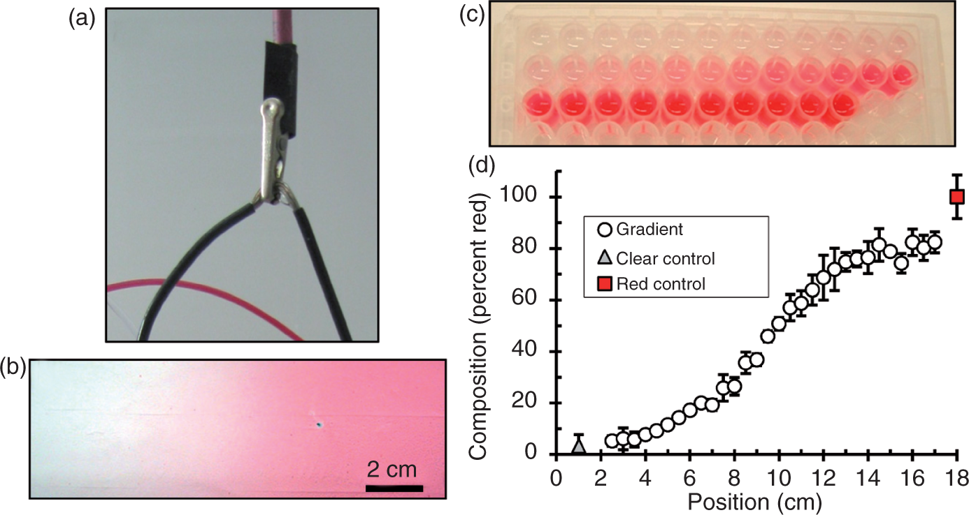
The 2-spinnerette system (Figure 1) was characterized by making PCL nanofiber scaffolds containing red dye (Sudan IV) gradients since the red dye is visible and can be quantified by absorbance measurements. Gradients were cut into sections and the red dye absorbance was measured to assess gradient generation (Figure 2). A plot of composition versus position for five red dye gradients shows that the composition went from 5% to 82% Sudan IV over a distance of 11 cm. The five gradients used for the data in Figure 2(d) were made on five different days and the average magnitude of the standard deviations for these data was 12%. Thus, the day-to-day variability in Sudan red gradient fabrication was 12%, demonstrating the repeatability of the custom-designed 2-spinnerette device (Figure 2).
A two-spinnerette device was designed to make nanofiber gradients. Two spinnerettes are placed side-by-side and used to electrospin two different polymer solutions to yield overlapping mats of nanofibers with different compositions. The two-spinnerette device for making nanofiber gradients was tested using red dye to enable easy characterization. (a)Photograph of wire connecting lead from power supply to the spinnerettes. A short piece of insulated wire (10 cm) was bared in the middle to connect to the power supply and the two ends of the wire were attached to the two spinnerettes. (b) Photograph of nanofiber scaffold gradient fabricated using two poly(ε-caprolactone) (PCL) solutions where one contained red dye. (c and d) Absorbance (440 nm) of dissolved scaffold sections were measured with a plate-reader to characterize the nanofiber gradient composition. Five libraries (17 cm × 6 cm) fabricated on different days were analyzed (n = 5). Error bars are SD.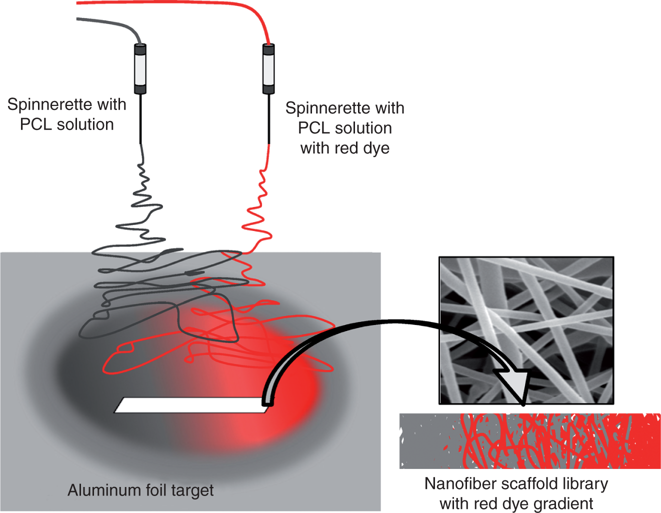
Getting repeatable gradients was challenging and a number of key parameters were identified that made the 2-spinnerette device effective. First, there cannot be any drafts. Electrospinning devices are commonly assembled in a hood (for solvent), but the draw of air into the hood leads to uneven fiber deposition and irregular gradients. Our unit was installed on a bench top, away from foot traffic, and was enclosed in plexiglass to shield from drafts. Second, there can be no metal parts (not even clamps) within 10 cm of the spinnerettes (only plastic or wood). Metal causes shorts and interferes with the electric field causing irregular electrospinning. Third, an insulated wire was used to connect the two spinnerettes to the power supply (Figure 2). This was critical to reduce the repulsion between the two spinnerettes so that the fiber jets would overlap and create a gradient. Fourth, having beveled syringe tips with bevels facing each other for the two spinnerettes and having the two spinnerettes offset 3 mm in the z-direction were essential for getting gradients. Without these modifications, the two streams repelled one another and their overlap wasminimal (no gradient). Thus, optimization of the 2-spinnerette design was demanding, but several modifications were implemented that made the device effective and reliable.
Next, nanofiber scaffolds with gradients of nACP were fabricated to demonstrate application of nanofiber gradients for tissue engineering. nACP powder was characterized by X-ray diffraction (XRD) and transmission electron microscopy (TEM; Figure 3) which showed that the nACP powder was amorphous and that it consisted of nanosized particles (≈100 nm). SEM was used to examine the morphology of the nanofiber scaffolds (Figure 3). Control PCL and PCL-nACP nanofibers had a similar morphology and a similar fiber diameter (control PCL diameter was 260 (95) nm and control PCL-nACP nanofiber diameter was 305 (151) nm as determined in scanning electron micrographs, means with standard deviation in parentheses, n = 10, not significantly different by t-test, p > 0.05). nACP particles were visible on the surface of the control PCL-nACP nanofibers. The morphology and diameter ofnanofibers with nACP gradients was similar to control nanofibers (not shown). In addition, little nACP was seen on fibers from nACP-poor regions of the gradients, while more nACP was visible on fibers from nACP-rich regions of the gradients (not shown).
Nanofiber mats containing a gradient in amorphous calcium phosphate nanoparticles (nACP) were fabricated to mimic an interface between bone and soft tissue. (a) X-ray diffraction (XRD) of nACP powder. (b) Transmission electron microscopy (TEM) of nACP particles. (c and d) Scanning electron microscopy (SEM) of control poly(ε-caprolactone) (PCL; 0 mass percent nACP) and PCL-nACP nanofibers (24 mass percent nACP). Arrowheads in (d) indicate nACP. (e) Higher magnification SEM showing nACP particle on the surface of a control PCL-nACP nanofiber.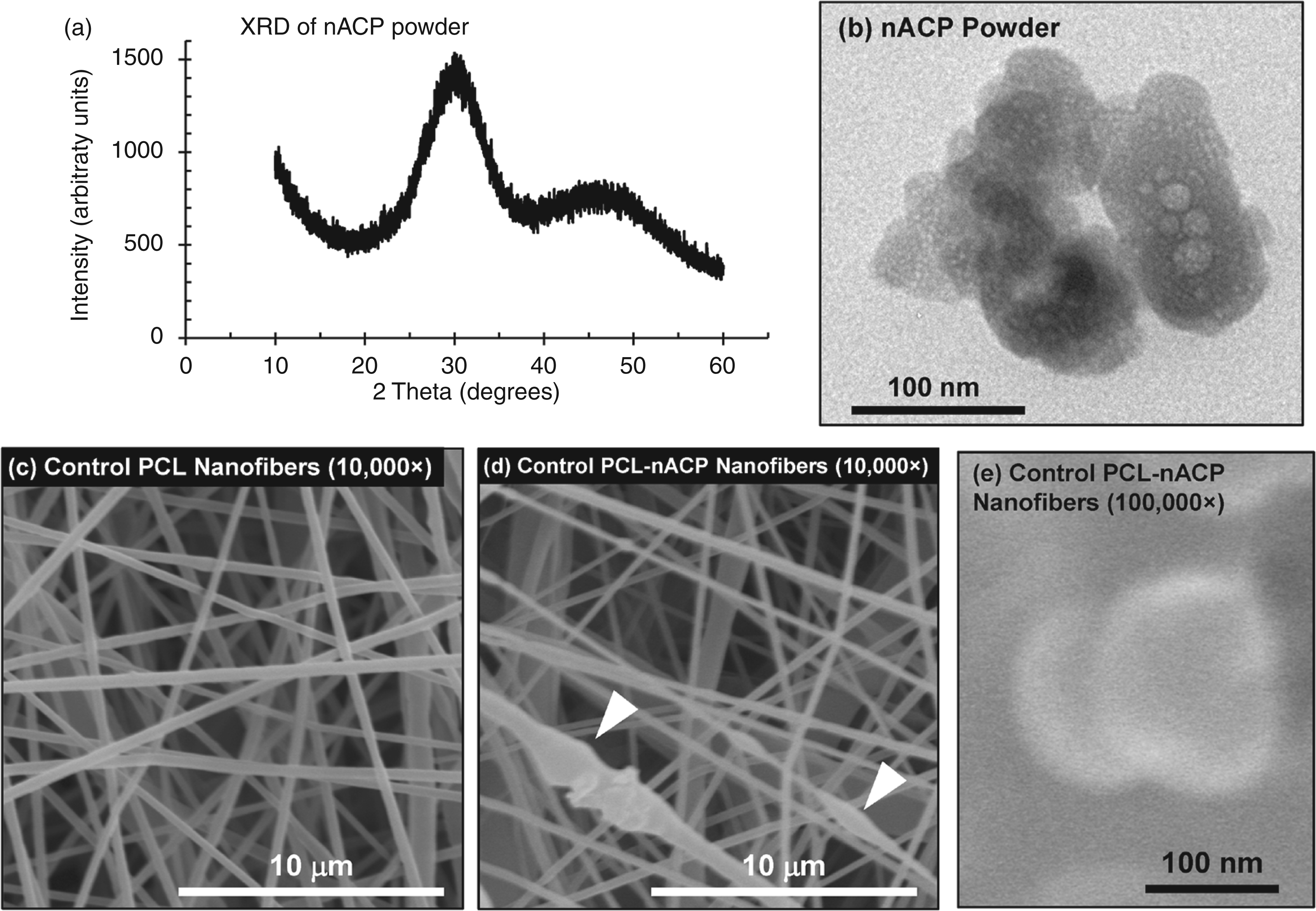
TGA yielded the composition of PCL-nACP nanofiber gradient scaffolds. Gradients went from 4% nACP to 20% nACP by mass over a distance of 13–15 cm. Electrospinning control PCL-nACP nanofibers using a polymer solution containing 30% by mass nACP (70% by mass PCL) yielded nanofibers containing 24% by mass nACP. Thus, gradients achieved 20% by mass nACP at the nACP-rich end of the gradient, even though control PCL-nACP nanofibers contained 24% by mass nACP. This was because the PCL-nACP nanofibers in the gradients were ‘diluted’ by the presence of some pure PCL nanofibers (coming from the spinnerette that was dispensing the pure PCL solution). Gradients fabricated on three different days had similar compositional profiles demonstrating the repeatability of the nACP gradient fabrication approach (Figure 4). The average magnitude of the standard deviations for thedata points in Figure 4(b) was 25%, giving a measure of the variability in the nACP gradient fabrication.
Composition of nanofiber mats containing an amorphous calcium phosphate nanoparticles (nACP) gradient was measured using thermogravimetric analysis (TGA). (a) TGA of nACP powder, control PCL-nACP nanofibers (24 mass percent nACP), and control PCL nanofibers (0 mass percent nACP). Poly(ε-caprolactone) (PCL) burns off during heating while nACP is stable, enabling determination of nACP content in PCL-nACP nanofibers. (b) nACP composition of nanofiber scaffolds determined by TGA. Solid circles are PCL-nACP nanofiber gradients (n = 3), open diamond is control PCL nanofibers (n = 5), and open triangle is control PCL-nACP nanofibers (n = 3). Error bars are SD. The three PCL-nACP nanofiber gradients were made on three different days to demonstrate the day-to-day variability in the nACP gradient fabrication.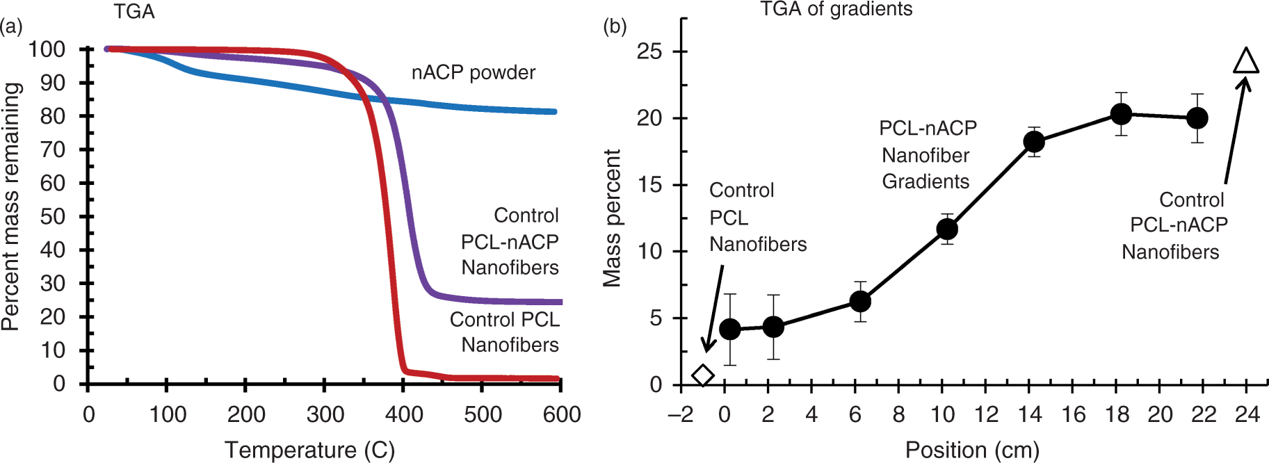
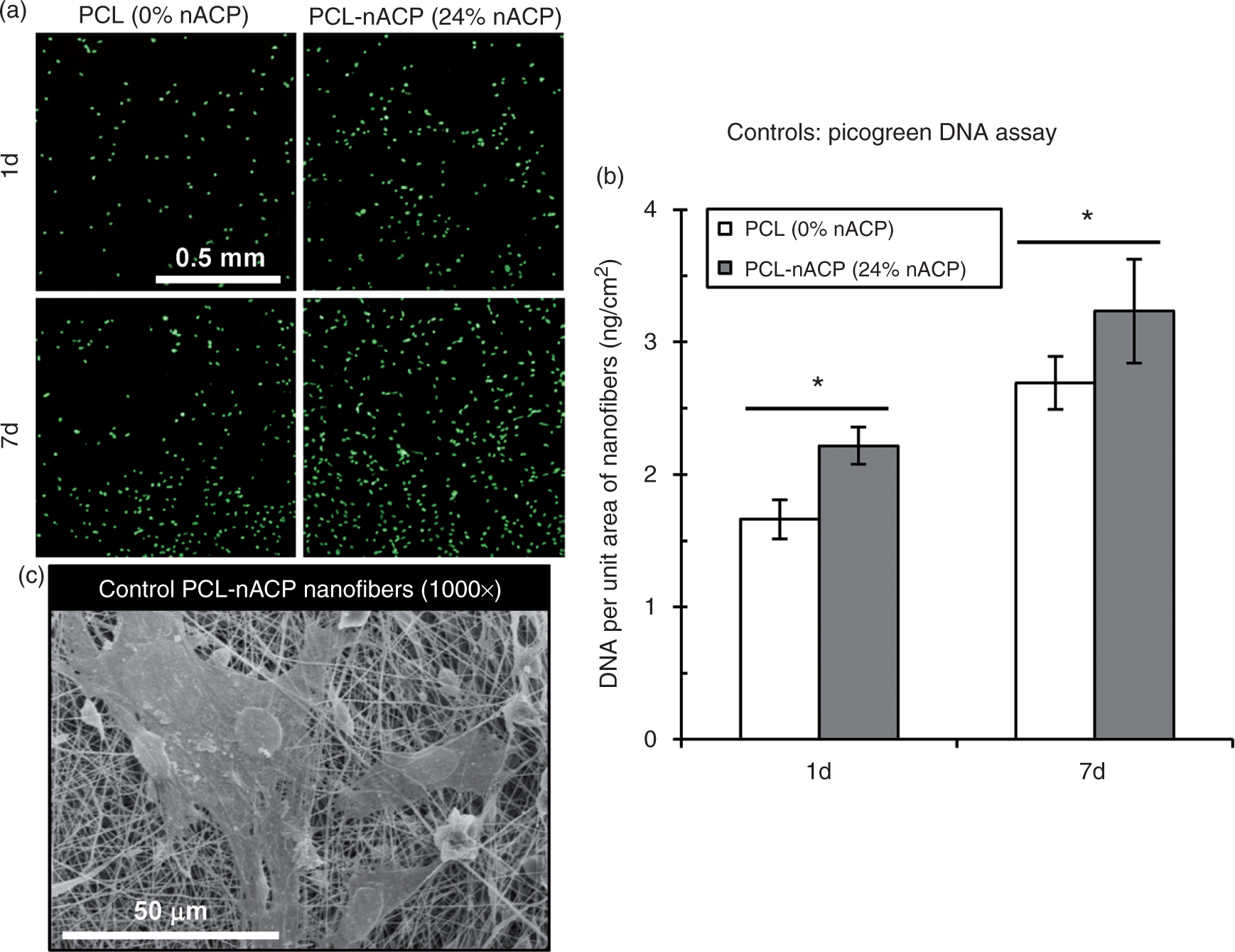
MC3T3-E1 osteoblasts were cultured on gradient nanofibers and fluorescence microscopy and the Picogreen DNA assay were used to assess cell response. Both cell adhesion (1 d) and proliferation (7 d) were enhanced on nACP-rich regions of the nanofiber gradients compared to the nACP-poor regions of the gradient (Figure 5). Increased cell numbers were detected with increasing nACP content by both fluorescence microscopy and by DNA assay. Statistical testing showed that differences in cell adhesion and proliferation were significant (p < 0.05). Control experiments using nanofiber specimens without gradients (uniform composition) were used to validate the gradient results (Figure 6). Cell numbers after 1 d and 7 d culture were significantly higher on control PCL-nACP nanofibers than on control PCL nanofibers (p < 0.05). Thus, nACP potentiated osteoblast adhesion (1 d) and proliferation (7 d) for both gradient and control nanofiber formats, which validates the gradient approach.
Adhesion and proliferation of MC3T3-E1 osteoblasts was enhanced with increasing amorphous calcium phosphate nanoparticles (nACP) content in the nanofiber gradients. (a) Photograph of eight PCL-nACP nanofiber gradients (22 cm × 1.5 cm strips) in a cell culture dish. (b) Nanofiber gradients were analyzed with cell culture assays. After culture, the two end sections were discarded (white) while the middle part was cut into 12 sections (1.5 cm × 1.5 cm) where 6 were used for Sytox green (‘SG,’ light grey) and 6 were used for Picogreen DNA assay (‘PG,’ dark grey). Note that SG and PG sections were paired into six positions and the nACP compositions are given. Compositions were determined from Figure 4(b) and the values are used in other figures. (c) Fluorescence images of green-stained nuclei of MC3T3-E1 osteoblasts cultured 1 d or 7 d on PCL-nACP nanofiber gradients. Scale bar applies to all images. Numbers indicate gradient position and mass percent nACP. (d) Picogreen DNA assay for cells cultured on PCL-nACP nanofiber gradients for 1 d or 7 d. Error bars are SD (n = 4). (e) Statistical analysis for Picogreen DNA data. Grey shaded boxes indicate significant differences for DNA amount from different positions in the nanofiber gradients (analysis of variance (ANOVA) with Tukey’s, p < 0.05). Control cell experiments using nanofiber specimens with uniform composition were used to validate gradient experiments. (a) Fluorescence images of Sytox green stained nuclei of MC3T3-E1 cells cultured 1 d or 7 d on control poly(ε-caprolactone) (PCL) nanofibers (0 mass percent amorphous calcium phosphate nanoparticles (nACP)) or control PCL-nACP nanofibers (24 mass percentnACP). The scale bar applies to all images in (a). (b) Picogreen DNA assay for cells cultured on control PCL nanofibers or control PCL-nACP nanofibersfor 1 d or 7 d. Error bars are SD (n = 12). Asterisks indicate significant differences (t-test, p < 0.05). (c)Scanning electron micrograph of MC3T3-E1 cells cultured 1 d on control PCL-nACP nanofibers.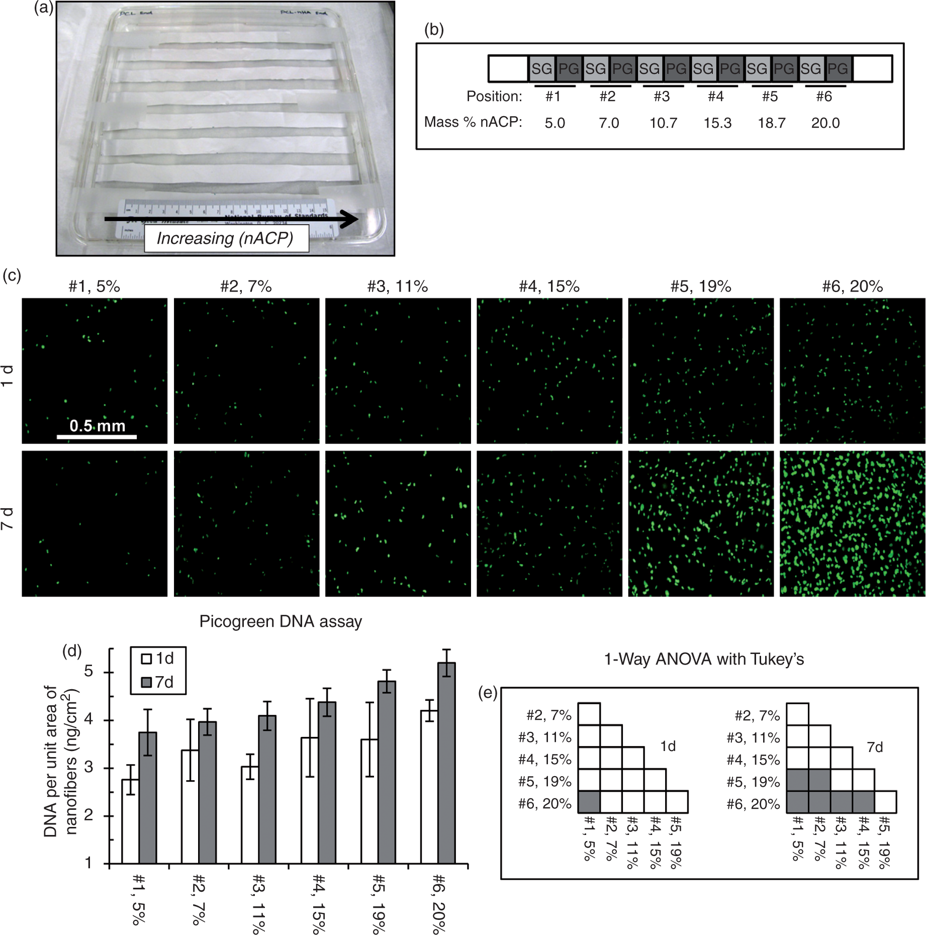
To explore the mechanism whereby PCL-nACP nanofibers promoted osteoblast function, the release of calcium and phosphate ions from nanofibers was measured (Figure 7). PCL-nACP nanofibers caused a significant increase in soluble calcium and phosphate concentration (p < 0.05) when incubated in cell medium whereas control PCL nanofibers did not (p > 0.05). These results show that nACP in the nanofibers partially dissolved during cell culture to release ions of calcium and phosphate which could stimulate osteoblast function. Calcium and phosphate ions have previously been shown to stimulate osteoblast proliferation and differentiation26,27 and an increase in these ions caused by nACP dissolution would be expected to do the same. In regard to calcium toxicity, MC3T3-E1 osteoblasts have previously been encapsulated in alginate hydrogels using 100 mmol/L CaCl2 crosslinking solution with no effect on MC3T3-E1 osteoblast viability indicating that osteoblasts can be tolerant of high calcium concentrations.
32
In addition, hepatocytes can be encapsulated in alginate using 100 mmol/L CaCl2 with only minor effects on cell viability.
33
Since calcium phosphate biomaterials can stimulate osteoblast function by release of calcium and phosphate ions, calcium and phosphate release from nanofiber scaffolds was measured. Change in calcium (a) and phosphate (b) concentration in cell medium after 15 min incubation with control poly(ε-caprolactone) (PCL) nanofibers (0 mass percent) or control PCL-nACP nanofibers (8 mass percent nACP). Error bars are SD (n = 3). Asterisks indicate that PCL-nACP nanofiber values were significantly different from blank controls and PCL nanofibers (1-way analysis of variance (ANOVA) with Tukey’s, p < 0.05). The percent change as compared to Blank is given on the bars for PCL and for PCL-nACP nanofibers.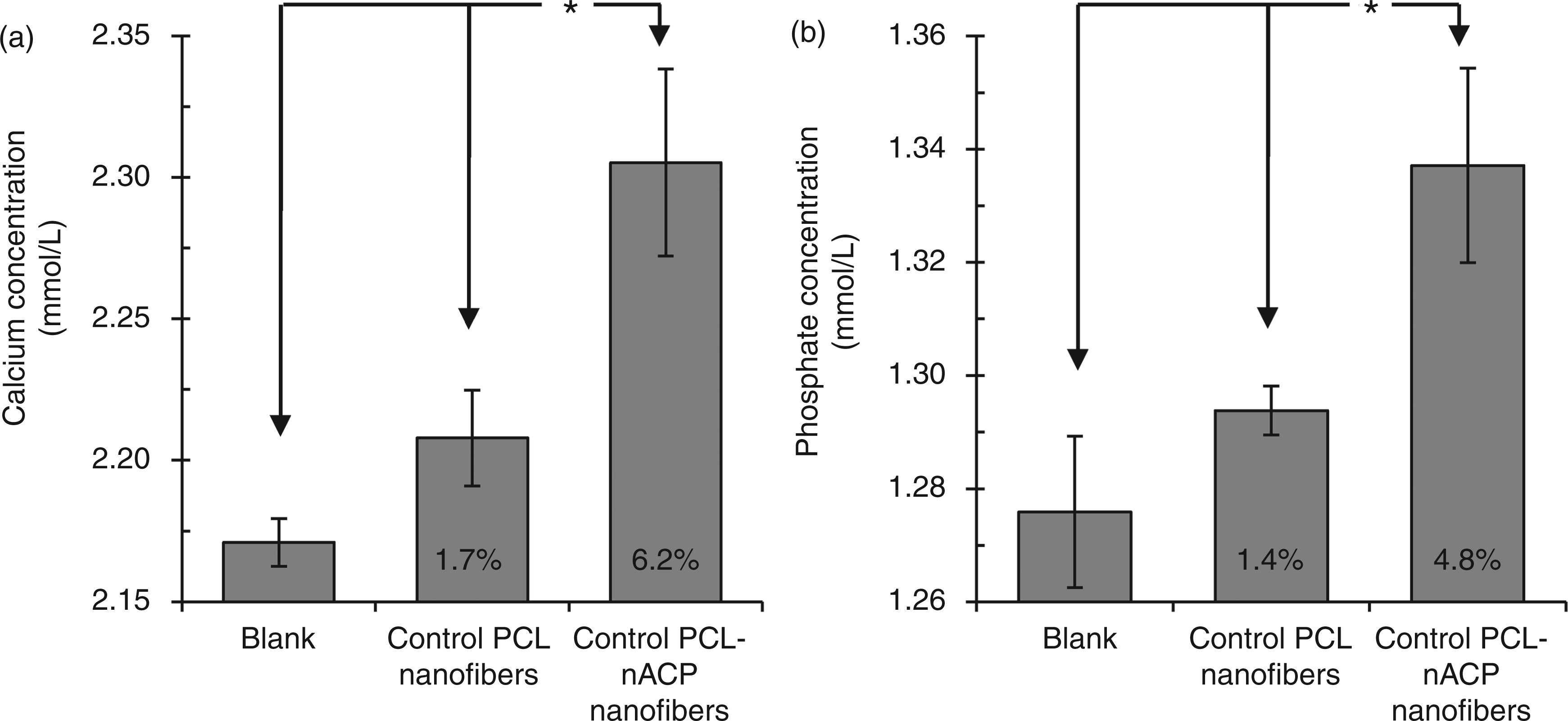
Discussion
We have demonstrated a new 2-spinnerette approach for electrospinning nanofiber gradients that is versatile and can yield nanofiber gradients from any materials that can be elctrospun (polymers, composites, nanoparticles, growth factors, peptides, etc.). Previously, successive layers of different nanofibers were spun into a layered mat,12,13 assembly of nanofiber gradients were directed by a magnetic field, 14 and nanofiber mats were differentially exposed to a reactive solution.15,16 These other nanofiber gradient approaches have required modification of nanofibers after electrospinning while the 2-spinnerette method described herein yields gradients directly.
Gradient nanofiber scaffolds can have application for engineering graded tissues.2--4 Ligaments and tendons join soft and hard tissues utilizing gradients from collagenous, fibrous tissue into hard bony tissue.2,3 The ligament to bone interface contains a gradation from noncalcified to calcified tissue. 2 The PCL-nACP nanofiber gradients fabricated herein induced a graded response in osteoblast adhesion and proliferation that could mimic these calcification gradients. The effective length of the current PCL-nACP nanofiber gradients ran from 4 cm to 17 cm as shown in Figure 4 (13 cm in length). For repair of Achilles tendon, 12 cm contructs have been used. 34 In addition, 10 cm grafts have been used for ligament reconstruction of the thumb. 35 Thus, the current PCL-nACP nanofiber gradients are in the appropriate size range for repairing Achilles tendon or thumb ligament in humans.
Many different approaches are being advanced forpatterned tissue regeneration. Self-assembly of microgels can be used to create hierarchically ordered hydrogel scaffolds.36,37 Photolithography can be used to generate microgels with different shapes, compositions, and cell types that can be assembled using physical phenomena such as the hydrophobic effect. 38 Freeform approaches can use focused light to photocatalyze polymeric gels with spatially patterned biomolecules with rationally designed architectures.39,40 Fluidic approaches can micromanipulate polymer solutions into heirarchical structures to yeild patterned hydrogel or porous polymer scaffolds.4,7,41--43 Each of these approaches has its own advantages that could help propel it to translation.
Nanofiber gradients can also have application for combinatorial screening.44–46 By making scaffold libaries where many scaffold formulations are contained in a single specimen, cell response to scaffold properties can be more efficiently and sytematically tested. 47 Biomaterials are frequently screened using a 2D format where materials are presented to cells as a flat surface. However, cells are responsive to the topography of their substrate and to scaffold architecture. Cells also behave more physiologically in a 3D envirnoment 48 than on a flat surface so that screening of biomaterials using a 3D scaffold can provide more relevant information. Thus, nanofiber gradients can be used for combinatorial screening of the effect of nanofiber properties on cell response.
Conclusions
In summary, a versatile 2-spinnerette method for fabricating nanofiber scaffolds with gradients in composition has been introduced that can be used to fabricate nanofiber gradients from any materials that can be electrospun. Several key device modifications were identified that make the approach reliable and effective. Application of the nanofiber gradients to tissue engineering was demonstrated by making gradients in nACP composition. Nanofiber scaffolds with gradients in nACP induced a graded response in osteoblast adhesion and proliferation. These results show that nACP nanofiber gradients may have application for engineering interfaces such as ligaments or tendons that transition from soft to hard tissue.
Footnotes
Acknowledgements
M.R., V.T., and K.C. acknowledge National Academies/NRC NIBIB/NIH-NIST Post-doctoral Fellowship program (National Research Council, National Institute of Biomedical Imaging and Bioengineering, National Institutes of Health). We thank G. Christopherson for help with figures. This work was supported by NIST, NIH/NIBIB R21 EB006497-01, NIH-NIDCR R01 DE16416, and the Intramural Program of the NIH/NIDCR (National Institute of Dental and Craniofacial Research). The ‘standard deviation’ (S.D.) is the same as the ‘combined standard uncertainty of the mean’ for the purposes of this work. The content is solely the responsibility of the authors and does not necessarily represent the official views of NIH, ADA (American Dental Association), NIBIB, NIDCR, or NIST. This article, a contribution of NIST, is not subject to US copyright. Certain equipment and instruments or materials are identified in the paper to adequately specify the experimental details. Such identification does not imply recommendation by NIST nor does it imply the materials are necessarily the best available for the purpose.