
Abstract
Heart valve-related disorders are among the major causes of death worldwide. Although prosthetic valves are widely used to treat this pathology, current prosthetic grafts cannot grow with the patient while maintaining normal valve mechanical and hemodynamic properties. Tissue engineering may provide a possible solution to this issue through using biodegradable scaffolds and patients’ own cells. Despite their similarity to heart valve tissue, most hydrogel scaffolds are not mechanically suitable for the dynamic stresses of the heart valve microenvironment. In this study, we integrated electrospun poly(glycerol sebacate) (PGS)–poly(ɛ-caprolactone) (PCL) microfiber scaffolds, which possess enhanced mechanical properties for heart valve engineering, within a hybrid hydrogel made from methacrylated hyaluronic acid and methacrylated gelatin. Sheep mitral valvular interstitial cells were encapsulated in the hydrogel and evaluated in hydrogel-only, PGS–PCL scaffold-only, and composite scaffold conditions. Although the cellular viability and metabolic activity were similar among all scaffold types, the presence of the hydrogel improved the three-dimensional distribution of mitral valvular interstitial cells. As seen by similar values in both the Young’s modulus and the ultimate tensile strength between the PGS–PCL scaffolds and the composites, microfibrous scaffolds preserved their mechanical properties in the presence of the hydrogels. Compared to electrospun or hydrogel scaffolds alone, this combined system may provide a more suitable three-dimensional structure for generating scaffolds for heart valve tissue engineering.
Introduction
Heart valve disease is a major ailment worldwide resulting in ∼300,000 surgeries annually, a number that is expected to increase over the next 30 years.1,2 Mechanical valves (MV) and bioprosthetic heart valves are currently the most common heart valve replacements.1,3 However, they are associated with a number of limitations. MV, although they rarely need replacement, are associated with an increased risk for thrombo-embolic complications and necessitate lifelong anti-coagulation therapy.1,3–6 Bioprosthetic valves have a shorter life span than MV (less than 15 years) due to mechanical failure and extensive calcification.1,3,7–9 However, the most important limitation of both mechanical and bioprosthetic valves is their inanimate nature, which inherently limits their use in pediatric patients because they do not grow along with the patient, necessitating recurring replacements. Tissue engineering strategies such as tissue-engineered heart valves can create autologous heart valve constructs that overcome these limitations by retaining the ability to grow and remodel over time.1,10–15
All four heart valves have a layered cellular structure, consisting of the valvular endothelial cells, the valvular interstitial cells (VICs), and valvular extracellular matrix (ECM). The ECM, the principal component of heart valves, consists of three layers: fibrosa, spongiosa, and ventricularis. These layers are composed of the fibrous macromolecules collagen, proteoglycans, and elastin, respectively, which confer the unique physical and mechanical properties of the native valve.3,7,16 Collagen accounts for ∼60% dry weight of the valve, elastin for ∼10%, and proteoglycans for ∼20%.16,17 VICs are located throughout all layers, from deep inside to the surface. ECM structure of heart valves is maintained by VICs. The VICs are not a homogenous cell population and are composed of cells from different phenotypes such as quiescent fibroblasts, activated myofibroblasts, and cells with progenitor-like phenotypes. 18 This unique three-dimensional (3D) environment can be mimicked by hydrogels, which can be generated via photocrosslinking and physical crosslinking to create homogenous encapsulated cell distributions within the structure. These structures can provide a suitable cellular niche for cell proliferation and differentiation through appropriate physical and chemical characteristics. Natural polymer-based hydrogels can be remodeled by cell-mediated enzymatic degradation. However, these polymers do not provide sufficient mechanical strength to withstand the constant stress that mechanically active tissues, such as heart valves, experience. Natural polymers can be chemically modified to incorporate photocrosslinkable moieties, such as methacrylates, so that they can form 3D hydrogel structures to control cellular activities. In our previous studies, we have developed photocrosslinkable natural polymers through acrylation chemistry. The modified natural polymers are cheap and cell-friendly material systems that are useful for biofabrication and can be used for creating hydrogel-based cell-laden tissue constructs.19–21
Hyaluronic acid (HA) is a natural, non-sulfated glycosaminoglycan that plays an important role in heart valve morphogenesis and wound repair.17,22–24 HA and its derivatives have been widely used as hydrogels for tissue engineering due to its inherent biocompatibility and biodegradability characteristics, as well as their gel-forming properties.22,25,26 Using HA as a heart valve tissue engineering material could provide key advantages because it has been shown to promote elastin secretion in VICs.24,27,28 Furthermore, HA can be modified to methacrylated hyaluronic acid (HAMA) and thus can be rendered photocrosslinkable upon ultraviolet (UV) exposure. However, HA alone does not promote cell spreading; thus, combining HAMA and methacrylated gelatin (GelMA) could provide a more suitable microenvironment for the cells. 17 However, these hydrogels lack the structural integrity necessary for heart valve tissue formation. The mechanical shortcomings of the hydrogel structure can be addressed by adding a microfibrous component to reinforce the structure and to provide contact guidance, which is essential for directing the internal organization of the cells.29–33 We recently engineered microfibrous poly(glycerol sebacate)–poly(ɛ-caprolactone) (PGS–PCL) synthetic scaffolds that could mimic the mechanical properties in the human aortic valve. 29 These fibrous scaffolds can be produced by electrospinning, resulting in a highly porous structure that retains desirable mechanical properties29,30,34–36 such that it can accommodate directional tensile loads while maintaining mechanical flexibility.6,9,33 However, the high porosity of the PGS–PCL microfibrous scaffolds allows seeded cells to migrate out of the structure. Furthermore, cells tend to attach only on the surface of the scaffold, which makes producing fully cellularized 3D structures difficult. 29
The goal of this study was to create a composite biomaterial that combines the advantageous properties of ECM-mimicking hydrogels and elastomeric PGS–PCL electrospun (ES) scaffolds to mimic the cellular environment and mechanical properties of native heart valve tissue. The hydrogel component of the composite scaffold developed in this study retains cells within the composite structure, while the PGS–PCL component provides mechanical strength and a porous structure to support tissue growth. A composite of gelatin and HA provides us with a similar ECM microenvironment to that of the VICs in vivo.16,17 However, in a hydrogel configuration, this structure lacks the mechanical properties necessary to withstand the dynamic environment of the heart valve tissue. Therefore, by inclusion of fibrous scaffold within the hydrogels, a more robust structure can be obtained. We used VICs to test the suitability of the composites’ physical and mechanical properties for heart valve tissue engineering by evaluating several physicochemical parameters, such as the swelling ratio, stiffness, porosity, and in vitro enzymatic degradation behavior, as well as the initial in vitro analysis.
Materials and methods
Synthesis of methacrylated HA and GelMA
HA sodium salt (Mn: 7.52 × 10⁵ kDa; Life-core Biomedical, Chaska, MN) was dissolved to a final concentration of 1% w/v in deionized water (dI H2O). The pH of the solution was monitored during this process. Methacrylic anhydride (Sigma-Aldrich, St. Louis, WI) was added dropwise (2 ml/200 ml) while maintaining the pH at 8.0. The solution was put on ice for several hours and was monitored every 15 min for checking the pH to be maintained at 8. The solution was agitated overnight in a cold room (4℃) and was then dialyzed for two days in distilled water (dI H2O) with multiple solution changes using 12–14 kDa molecular weight cut-off (MWCO) dialysis tubes. The solutions were lyophilized for one week, and the final product was stored at −80℃ for future use.
Porcine skin type A gelatin (Bloom index 300; Sigma-Aldrich, Madison, WI) was methacrylated as described previously. 19 Briefly, 10% (w/v) gelatin was mixed in Dulbecco’s phosphate-buffered saline (DPBS; Invitrogen, Grand Island, NY) and incubated at 60℃ until completely dissolved. Methacrylic anhydride (0.8 ml/g) (8 ml) was added dropwise at a rate of 0.5 ml/min into the gelatin (10 g) solution. The emulsion was agitated at 60℃ for 1 h. Warm 2× DPBS (40℃) was added to the solution to prevent any further reaction. The solution was dialyzed for one week in distilled water using MWCO dialysis tubes (12–14 kDa) with several solution changes. The freeze-drying of the solution for one week then resulted in white, porous foam that was kept at −80℃ to be used in the future.
PGS–PCL microfibrous scaffold formation
PGS–PCL microfibrous scaffolds were prepared by using a standard electrospinning setup. The copper wire was covered with a non-adhesive special tape with a glass slide on top, which acted as a framework. PGS (MW 12,000; gift from Langer Laboratory, Department of Chemical Engineering, MIT, Cambridge, MA) and PCL (MW70,000–90,000; Sigma-Aldrich, Madison, WI) were dissolved at a 2:1 ratio in anhydrous chloroform–ethanol (Sigma-Aldrich, Madison, WI) (9:1 v/v) and were electrospun at 12.5 kV. The total polymer was 33%. Pure PCL scaffolds were electrospun using 16% w/v polymer solution because it was difficult to electrospin the highly viscous 33% w/v PCL solution. 29 The fibers were fabricated, while the distance between the needle (21-gauge needle) and the collector was kept at 18 cm, at a flow rate of 2 ml/h. Each sample was fabricated in 20 min; the resulting scaffolds were dried overnight in a vacuum desiccator and all residual solvents were removed.
Hydrogel preparation
A hydrogel precursor solution (2.5% GelMA macromer, 0.5% HAMA macromer) was mixed with endothelial basal medium (EBM-2; Lonza, Walkersville, MD). The solution was crosslinked by adding the photoinitiator (PI) 2-hydroxy-1- (4-(hydroxyethoxy) phenyl)-2-methyl-1-propanone (Irgacure 2959, BASF, Ludwigshafen, Germany) to a final concentration of 0.1% (v/w) and exposing it to UV light (λ = 408 nm) for 45 s at 2.6 mW/cm2. The resulting hydrogel (20 μl initial solution volume, ∼6 mm diameter, ∼0.5 mm thick) was used as a control and was also used for making the composite scaffolds.
Fabrication of composite hydrogel/microfibrous PGS–PCL scaffolds
PGS–PCL bulk sheets were used to create 6-mm diameter scaffolds. The PGS–PCL scaffolds were put into contact with the precursor hydrogel solution (20 μl; 2.5% GelMA/0.5% HA/0.1% PI). Once the scaffold fully absorbed the solution, the resulting composite was crosslinked using UV light (λ = 408 nm, 2.6 mW/cm2, 45 s).
Hydrogel precursor solution soaking into PGS–PCL and PCL fibers
Scaffolds (6-mm diameter) were created from both PGS–PCL and PCL-only (negative control) and were then filled with 20 μl hydrogel solution (2.5% GelMA/0.5% HAMA/0.1% PI) by putting the solution volume on top of each scaffold. Soaking of the drop into the PGS–PCL actual fibers was imaged as both sequential series (1-s intervals) and in video format. PCL-only scaffolds were used as the negative control.
Physical characterization of the scaffold
Mechanical properties
For mechanical characterization of the samples, a uniaxial elongation test was performed on at least six samples using an Instron 544 (Instron, Norwood, MA) and a 10 -N load cell. ES meshes were cut into rectangular shapes (5 mm × 20 mm). In order to prepare composite samples for mechanical testing, PGS–PCL scaffolds were cut and placed in the molds. Molds were filled by pipetting 20 μl hydrogel solution (2.5% GelMA/0.5% HAMA/0.1% PI) on top of each ES scaffold. Composites were formed by exposing the mold to the UV light (λ= 408 nm, 2.6 mW/cm2, 45 s) and then detached from the mold. The composite samples were tested while still wet. Sandpapers were attached to the top and bottom of the composite samples to prevent them from slipping before failure. The samples were loaded at a rate of 7 mm/min. The elastic modulus (EM) was measured using the Young’s modulus based on the linear portion of the stress–strain curve. The ultimate tensile strength (UTS) was calculated using the maximum strength obtained from the stress–strain curve.
Swelling ratio
Hydrogels and composite scaffolds were prepared as described above. The swelling behavior of the hydrogel and the composite was studied after equilibrating the samples in PBS at 37℃ for 24 h. The excess liquid was removed from the completely swollen samples before weighing (swollen weight). The samples were then freeze-dried and weighed again (dry weight) (n ≥ 6). The swelling ratio was measured by dividing the samples’ swollen weight by the dry weight. For the composites, the dry weight of the PGS–PCL scaffold was measured and subtracted during the calculation of swelling ratio.
In vitro hydrogel and the composite scaffold’s enzymatic degradation
Hydrogel samples (n ≥ 6) were crosslinked as described above. Collagenase (1 U/ml) from Clostridium histolyticum (Sigma-Aldrich, Saint Louis, MO) and hyaluronidase type 1-S (100 U/ml) from bovine testes (Sigma-Aldrich, Saint Louis, MO) solutions were prepared in PBS from stock solutions. Samples were incubated in collagenase (1U/mg; n ≥ 6), hyaluronidase (100 U/ml; n ≥ 6), or PBS (n = 6) at 37℃ for 24 h. The samples were weighed before and after adding the enzymatic solution. After incubation, the samples were washed, lyophilized, and weighed again. The degradation was calculated by determining the decrease in mass. The samples were stored at 37℃ for 48 h before fixing them in 2.5% glutaraldehyde and observing the hydrolytic degradation via scanning electron microscopy (SEM).
Scanning electron microscopy
Scanning electron microscopy (SEM) images were taken with the use of a field emission scanning electron microscope (FE-SEM; JSM 6700, JEOL, Peabody, MA) to characterize the pore size of the scaffold and the fiber morphology. Images were taken from both surface and internal cross-sections of the hydrogel-only, the composite scaffold, and the PGS–PCL-only scaffold with and without cells (day 0, day 21). The samples were fixed in 2.5% glutaraldehyde and were frozen using liquid nitrogen. Then they were stored at −80℃. The samples were lyophilized before sputter coating them with an iron coater using palladium and platinum. The SEM was equilibrated at 40 mA for 40 s prior to taking the images.
Mitral valvular interstitial cells
Cell culture
Mitral valvular interstitial cells (MVICs; gift from Dr Bischoff, Children’s Hospital, Boston, MA) having passage numbers between 3 and 4 were maintained in EBM-2 (Lonza)supplemented with 10% fetal bovine serum (Sigma-Aldrich, Saint Louis, MO) and 1% penicillin–streptomycin (Gibco, Langley, OK) at 37℃ and 5% CO2. Cells were cultured on gelatin-coated flasks and were passaged weekly with media changed every other day.
Encapsulation of MVICs within hydrogels (GelMA/HAMA) and composite scaffolds
MVICs were trypsinized and re-suspended in the hydrogel precursor solution (2.5% GelMA/0.5% HAMA) containing 0.1% (w/v) PI at a concentration of 6 × 10⁶ cells/ml. The hydrogel and composite scaffolds were fabricated as previously described. The scaffolds and hydrogel precursor solution with cells were exposed to 2.6 mW/cm2 UV light (408 nm) for 45 s and were then incubated in medium (EBM2) under standard culture conditions for 21 days. The medium was changed every 30 min for the first 2 h to remove the remaining PI. The medium was then changed every other day.
Seeding MVICs on PGS–PCL scaffolds
PGS–PCL scaffolds were sterilized prior to seeding the cells by immersing them in 70% ethanol for 2 h. It was followed by UV exposure and washing with DPBS. Then, the cells were seeded onto scaffolds (0.6 cm × 0.6 cm) at a concentration of 2 × 10⁴ cells/scaffold. Cells were seeded onto scaffolds by adding 20 μl of cell suspension to scaffolds in 48-well plates and incubating them for 1 h to allow the cells to attach. The medium was changed every other day.
Cell viability, attachment, spreading, proliferation, and metabolism
Cell viability
The cell viability within the scaffolds was quantified with the use of a Live/Dead assay (Calcein-AM/Ethidiumhomodimer; Invitrogen, Carlsbad, CA) per manufacturer’s protocol. The viability of the cells was determined on days 1 (24 h after cell seeding/encapsulation) and 21 of culture for each type of sample. The samples were imaged using a Nikon Fluorescent microscope. Image J software was used to assess the percent viability.
Cell attachment and cell spreading
Cell adhesion studies were performed by encapsulating 6 × 10⁶ cells/ml MVICs with each scaffold mentioned above and incubating them for 21 days. Media of the samples were changed every other day. After 21 days, the scaffolds were fixed and stained by rhodamine-phalloidin (Invitrogen, Grand Island, NY) and 4, 6-diamidino-2-phenylindole (DAPI; Invitrogen, Grand Island, NY).The degree of cell attachment and spreading was assessed by FE-SEM.
Cell metabolism
The metabolic activity of cells on each scaffold or hydrogel at days 1 and 21 of culture was assessed with the use of the Alamar Blue (AB) assay according to manufacturer’s protocol (Invitrogen, Carlsbad, CA). Cells were seeded onto scaffolds or were encapsulated within plain hydrogels or composite scaffolds (n = 3/group). The cell-seeded scaffolds were then transferred to new wells to avoid counting cells that had adhered to the plate surface during seeding. One well, which contains only medium, was used to measure background signal, while two cell-free scaffolds/hydrogels were used as the negative controls. The control scaffolds had the same no-cell condition for each type, as the baseline readings were not the same and this was taken into account in calculations. AB was dissolved in 10% v/v medium and then added to each well. The samples were kept in an incubator in AB for 2 h at 37℃. Subsequently, solution from each well was transferred to wells in a 96-well plate (100 μl, n = 3/group), and the fluorescence was measured (excitation: 540 nm, emission: 590 nm). The 21-day measurements were normalized to the corresponding measurements from day 1.
Statistical analysis
Statistical analysis was performed using SPSS version 15.0 (SPSS Inc., Chicago, IL). Data are shown as the mean ± standard deviation (SD). Kolmogorov–Smirnov test was performed to determine if the factors are normally distributed. Three groups of PGS–PCL fiber, hydrogel, and composite were compared by one-way analysis of variance. This was then followed by Tukey HSD test. Independent T-test was performed for comparison of mean of composite, hydrogel, and PGS–PCL groups. A p value ≤0.05 was considered statistically significant. Data are shown as the mean ± SD.
Results and discussion
Physical characterization of the composite scaffolds
As we have previously demonstrated,
29
the presence of PGS renders PGS–PCL microfibrous scaffolds more hydrophilic which enable their further modification. In this study, this modification is combined with the addition of an ECM-like microenvironment within and around the microfibers by adding the hydrogel. We initially wanted to ensure that the hydrogel fully penetrated the pores of the microfibrillar PGS–PCL scaffold during the creation of the composite scaffolds to ensure that the encapsulated cells would be homogenously distributed. SEM images of the composites show that the scaffold fibers were completely encapsulated within a layer of hydrogel (Figure 1(b)). The PGS component of the microfibers was necessary to facilitate this complete interface because the GelMA/HAMA gel solution was unable to penetrate the PCL-only fibers (see supplementary Figure S1). Additionally, the gel solution was absorbed more quickly when the scaffold was immersed in the gel solution compared to directly adding it to the scaffold structure. Thus, the composite structures were synthesized using this immersion technique. Previously, fiber/hydrogel composite constructs were prepared by simultaneous electrospinning of the microfibers and electrospraying of the hydrogel because of the utilization of hydrophobic polymers.
37
The advantage of the currently presented method is due to the ability of the PGS–PCL microfibers to imbibe hydrogel precursor solution, the composite can be produced after electrospinning, and cells can be directly encapsulated within the composite during hydrogel crosslinking step.
Fabrication of the fiber-reinforced hydrogel (2.5% GelMA+0.5% HAMA) scaffolds. (a) Schematics of the design and fabrication. Simply, it is possible to immerse the electrospun fibers inside the hydrogel precursor solution (to which cells can be added) and then crosslink via light exposure to form a cell-laden hydrogel with electrospun fibers for reinforcement. Presence of PGS allows for rapid immersion of the fibers into the hydrophilic gel precursor (cf. supplementary Figure S1). (b) Surface and cross-section SEM images of hydrogel, PGS–PCL fiber, and composite showing the integration of the hydrogel with the electrospun fiber.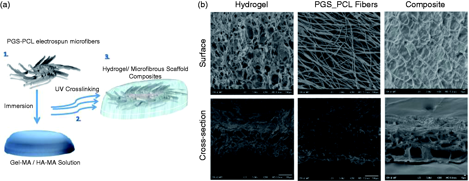
Another advantage of a hydrogel/ES scaffold composite is that the cells can remodel the structure without compromising its mechanical properties. The gel component will be enzymatically degraded in vivo during the remodeling process which is a crucial step in tissue healing. However, as enzymatic degradation of gelatin and HA happen at different rates, the stability of the composite under enzymatic degradation conditions was evaluated. The composite scaffolds were incubated with ECM-degrading enzymes to observe the changes in the network of crosslinked GelMA/HAMA. The gel component was almost completely degraded (92.0 ± 8.0%) after 24 h of collagenase treatment at 37℃, which showed that the enzymatic degradation of GelMA also partially removed the HA. Hyaluronidase treatment produced similar results, resulting in nearly 50% weight loss (45.94 ± 8.1%). The temporal and spatial degradation profile of a hydrogel affects kinetics of the remodeling process in vivo, thus illustrating the advantage of using a fibrillar scaffold/hydrogel composite. SEM images of the composite after collagenase degradation (Figure 2(a) and (b)) show that the overall shape of the scaffold was preserved even after the hydrogel component had been degraded. However, the gel component was left relatively intact after hyaluronidase digestion, and PBS incubation removed only a small amount of the gel via surface degradation, leaving the fibers completely embedded within the gel structure. The swelling ratio of the hydrogel component with and without the PGS–PCL scaffold was determined to evaluate the effect of the microfibrillar mesh on the degree of hydrogel crosslinking (Figure 3(a)). The swelling ratio of the composite samples significantly increased (p < 0.05), which could be caused by attenuated UV exposure, creating a low level of crosslinking in the areas beneath the fiber layer.
Degradation characterization of the composite scaffold fabricated by immersing PGS–PCL fibers into GelMA–HAMA hydrogel precursor solution. Hydrolytic and enzymatic degradation profile of the composite scaffold in PBS, collagenase, and hyaluronidase up on 24 h incubation. Degradation was (a) quantified through dry mass measurements of the samples incubated in enzyme (hyaluronidase or collagenase) or PBS (hydrolytic degradation) for 24 h (n = 6) and (b) examined using SEM. Physical characterization of the composite compared to the hydrogel and the fibers alone. (a) Swelling ratio of the composite compared to hydrogel (n = 6, p < 0.05). (b) Tensile mechanical properties of the composites compared to fibers (n = 6). Note that the composite scaffold has similar tensile mechanical properties to the fibers alone (p > 0.05). Such scaffolds might be preferable for cell applications that require high diffusion with high mechanical strength.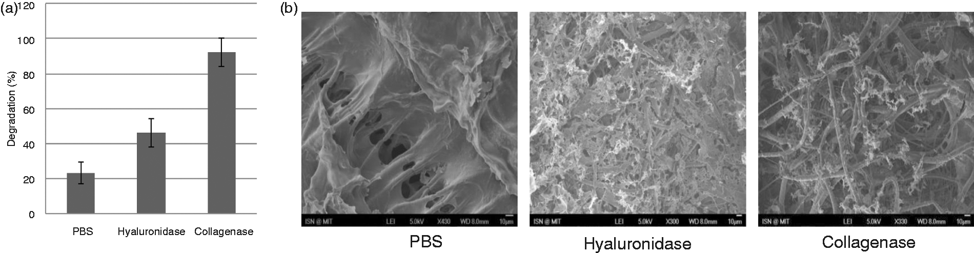
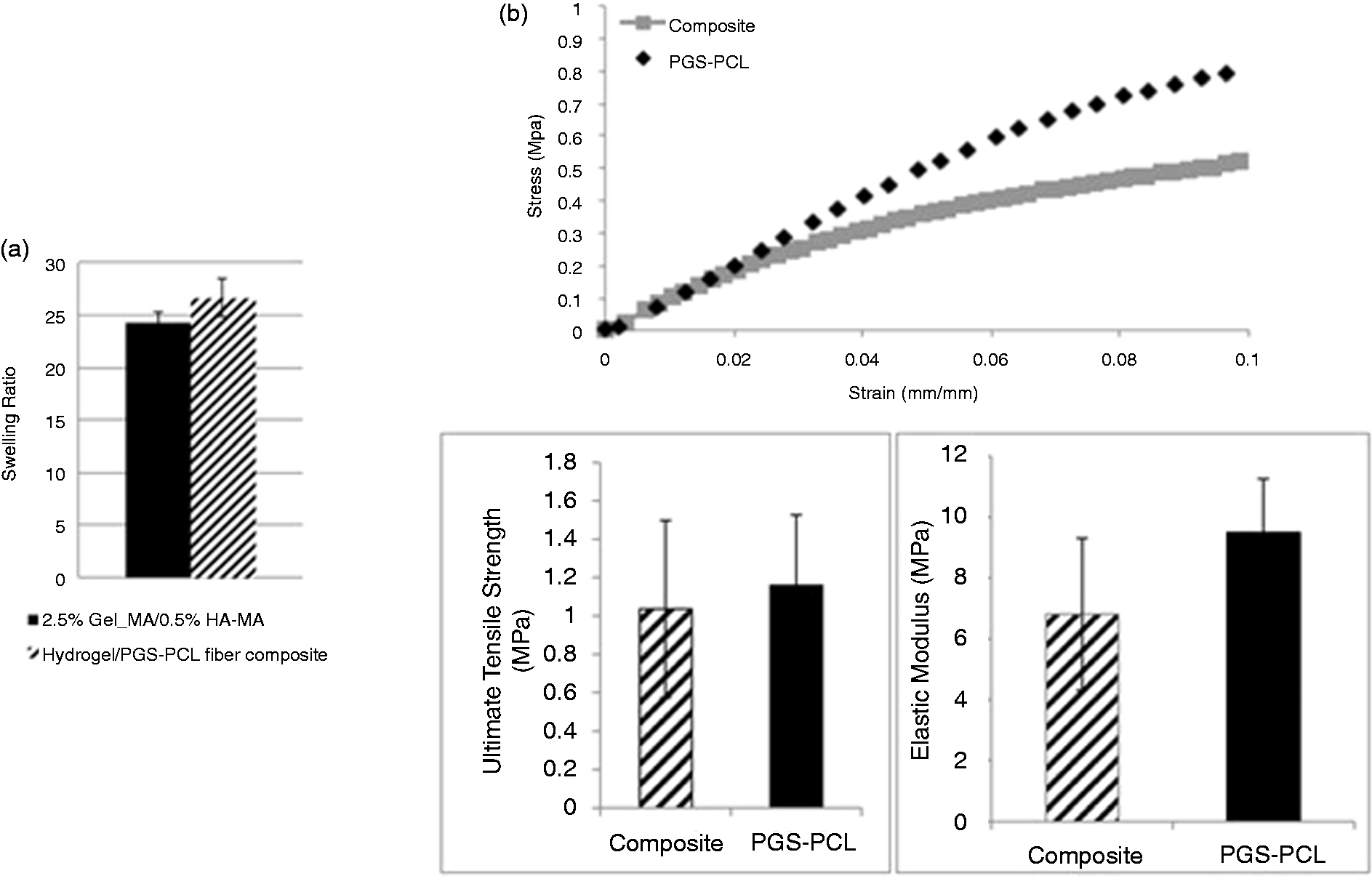
Native heart valves experience significant mechanical forces; therefore, the mechanical properties of a heart valve replacement must withstand the same forces. Native heart valves experience stretch and flexure during diastole and systole, respectively. 3 The stress and flexure distribution values have been described and recreated on precisely in Engelmayr et.al. scaffolds that were cultured in bioreactors. These forces are due to the cyclic loading stemming from the pulsatile nature of blood flow. There are also bending stresses due to the curvature reversal. Engelmayr et.al. 38 used a 1 Hz frequency at a flexure angle of 62° to mimic these stresses in vitro which is nearly equivalent to the normal heart beat rate. The heart valve ECM has a layered structure with fibrous, collagen-rich regions and glycosaminoglycan-rich regions. This layered structure contributes to a heterogeneous VIC phenotype. Previous studies have found that the shear forces and tensile stresses exerted during valve cycles within the heart valve are differentially distributed. 3 Our composite system mimics this structure, recapitulating the collagenous layers via the fibrous PGS–PCL scaffold, which provides mechanical strength while providing a 3D glycosaminoglycan-rich ECM-like microenvironment which can be remodeled by the cells in order to achieve a heterogeneous VIC phenotype. Our group has previously created PGS–PCL microfibrous scaffolds by comparing mechanical properties to those of native heart valves. 29 In this study, the base of the scaffold was microfibrous PGS–PCL scaffold. GelMA/HAMA was added to overcome the porosity issue and let the cells penetrate all the way inside the scaffold. Since PGS–PCL stiffness and ultimate tensile stress are in the order of MPa, and it was expected that adding GelMA/HAMA with much lower mechanical stiffness did not affect the overall mechanical properties of the composite compare to PGS–PCL scaffolds. Just the initial 10% of the stress–strain curve was depicted with which the stiffness of the scaffolds was measured (Figure 3(b)). However, as the deformation shown previously, 29 random PGS–PCL fibrous has a unique mechanical characteristic. The fibers can expand and specifically deform up to almost 600%. In this case, adding GelMA-HAMA may have less effect on the strain to failure of the composite. Adding GelMA-HAMA to PGS–PCL results in a composite that preserves the mechanical characteristic of PGS–PCL scaffolds which mimics the native values. 28 As expected, due to inconsiderable mechanical characteristic of GelMA/HAMA compared to PGS–PCL scaffolds, the mechanical properties of the composite scaffolds remained similar to that of PGS–PCL scaffolds. Therefore, adding the hydrogel component to PGS–PCL scaffolds did not significantly change the mechanical properties including the EM and the UTS.
In this study, it was confirmed that the overall hydrogel component provides an environment to encapsulate cells in 3D without significantly (p > 0.05) reducing the mechanical properties of the PGS–PCL structure and that the fibrous components still dominated mechanical properties of the composite (Figure 3(b)). Previously, porous PGS scaffolds had been used for culturing VICs, 39 but the Young’s Moduli and UTS of these scaffolds were lower than that of the dense ES scaffolds reported in this study. The mechanical property of our construct is in the range of the native heart valve tissue mechanical properties, where EM is 6.7 ± 1.1 MPa and UTS is 1.0 ± 0.21 MPa. 39 The advantage of porous 3D scaffolds over ES fibers with respect to the cell distribution is overcome in the hydrogel/ES composites by the encapsulation of the cells in the hydrogels.
MVIC encapsulation
From cell encapsulation point of view, adding a gel-based cell carrier to a microfibrous scaffold provides a higher scaffold volume without compromising the mechanical properties, which ensures that the cells are distributed within the entire volume of the scaffold rather than limiting the cells’ adhesion to the surface of the fibers, as it happens with bare fibrous structures. The hydrogel also provides a cellular niche that is more easily remodeled because it is enzymatically degradable and contains natural polymers present in the native heart valve. Environmental cues from events such as ECM damage change the phenotype of VICs within native heart valve tissue. A degradable hydrogel structure may help with the stimulation of the VICs to secrete ECM. Previous research has shown that adding glycosaminoglycans can increase VICs’ ECM production (collagen types I and III) within collagen gels. 40 However, the researchers incorporated uncrosslinked chondroitin sulfate, a glycosaminoglycan, which eluted quickly from the structure. Thus, our system is advantageous because it incorporates a crosslinked glycosaminoglycan component which forms crosslinks with the other ECM-like component, gelatin, thus it cannot be leached out during long cell culture periods.
HA is known to stimulate elastin production. 41 Furthermore, the presence of HA prevents calcified nodule formation by VICs in vitro. 42 GelMA/HA composites have been proven beneficial in other systems, such as HA hydrogels with encapsulated gelatin-conjugated particles. These HA-based structures were able to direct the osteogenic differentiation of mesenchymal stem cells, while HA gels alone induced cells to form unconnected spheroids. 43 A low level of HA was chosen for two reasons: (i) to obtain more robust structures and (ii) to prevent it from adversely affecting VIC phenotype. High levels of glycosaminoglycans were observed in the mitral valves of patients with congestive heart disease. 44 HA comprises 60% of glycosaminoglycan content of heart valves, and it has been implicated in myxomateous hearts, there is an increase in HA content of heart valves with aging process. 42 Suggesting that a high content of glycosaminoglycans might adversely affect VIC phenotype rather than facilitating ECM production.
After encapsulating the cells in either hydrogels alone or the composite hydrogel/PGS–PCL scaffolds, the MVICs were shown to be homogenously distributed and maintained their viability. The cellular distribution was uniform in the hydrogels, while the cells within the composite scaffolds were distributed more unevenly (Figure 4(a)). The cells initially assumed a rounded shape but then began to spread over time. By day 21, the cells had spread fully in both the hydrogel and composite structures; however, the bare PGS–PCL scaffold had cells spreading predominantly on its surface because the dense structure of the ES fibers temporarily limits cellular infiltration. Previous research using matrix metalloproteinase-degradable poly(ethylene glycol) gels showed that a high density of crosslinking can impede the encapsulated VICs’ spreading for up to 14 days
37
; thus, a low concentration hydrogel better facilitates cellular remodeling. After 21 days of culture, the composite scaffolds showed significantly more cells around the fibrillar component (Figure 4(b)), which may be caused by cellular migration toward stiffer substrates. The initial encapsulation process maintained a high level of cell viability (≥90%). At day 21, the viability of MVICs was still above 90% for all three scaffolds (Figure 4(c)), accompanied by a significant increase in the cell number. The metabolic activity of seeded cells was used as an indirect method for determining cell number. The cells within the composite scaffolds showed higher metabolic activity compared to those on the scaffold only or within the hydrogel samples at all time points (Figure 4(d)). The metabolic activity showed distinct peaks at various time points for the samples, which could be caused by the cells attaining a quiescent state when a certain cellular density was reached.
Behavior of cells encapsulated in composite scaffolds compared to cells encapsulated in GelMA/HAMA hydrogel and or seeded on PGS–PCL fibers alone. (a) Viability of the encapsulated or seeded cells as observed through Live/Dead staining of the MVICs on days 1 and 21. (b) Quantification of the Live/Dead images by Image J, (n = 3). (c) DAPI/phalloidin staining on day 21 showing cell spreading and distribution. (d) Metabolic activity determined using Alamar Blue (n = 3, p < 0.05).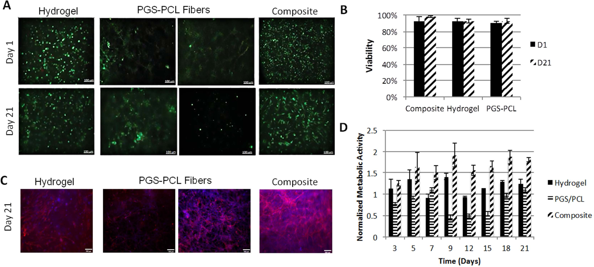
The results from SEM images of the scaffolds showed similar trends (Figure 5). VICs attached to single fibers or bridged adjacent fibers within the PGS–PCL-only scaffolds. The scaffold cross-sections show cells at different depths that are not well distributed throughout the scaffold (Figure 5). However, the VICs within the composite structures were observed at different depths and in greater numbers on the fibrous component due to the migration of cells within the hydrogel component.
SEM images of MVIC-seeded GelMA/HAMA hydrogel, PGS–PCL, and composite on day 21. Surface and cross-section images of the hydrogel, composite, and PGS–PCL scaffolds on day 21 with and without MVICs (arrows shows the cells). As visible in the last row, there are regions of the composite scaffold in which hydrogel appears degraded. In these images, arrows show that the cells remained on the fibers upon degradation of the hydrogel part of the composite scaffold.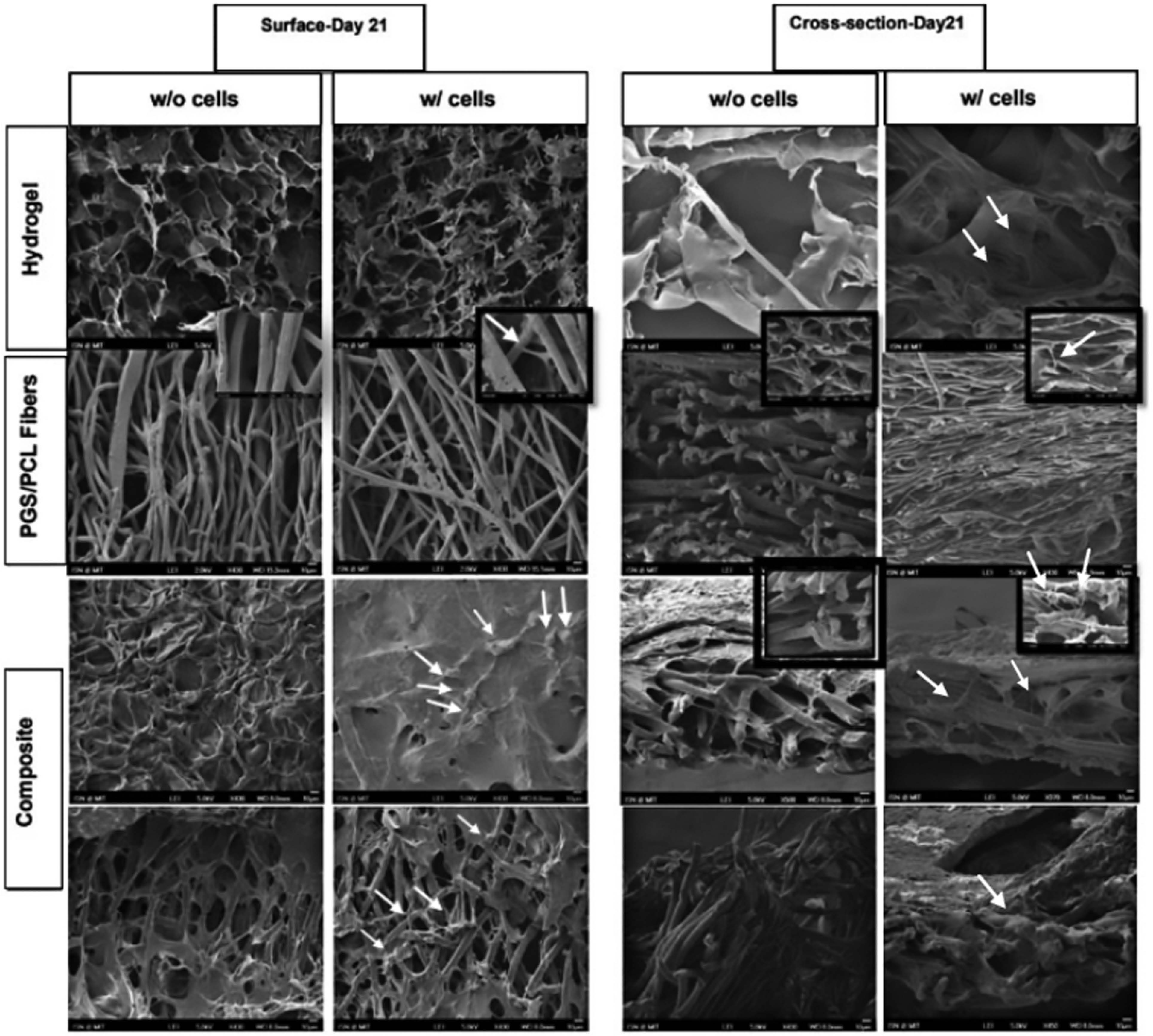
Previous research showed similar results for microfibrillar polyurethane/ECM-based hydrogel composites that were implanted in vivo as abdominal wall replacements. In this case, the bare ES scaffold samples showed limited cell infiltration, whereas the hydrogel/polyurethane (PU) composites showed cells infiltrating the full thickness of the scaffold by week 4. The mechanical properties of these structures were also determined by the fibrillar component, where a higher amount of ES fibers created higher tensile strength and suture strength. 45 Using highly crosslinked hydrogels, such as fibrin gels, together with a photocrosslinkable component can also cause changes in the overall mechanical properties of the composite. 46 However, the amount of time necessary to achieve such properties is not compatible with cellular encapsulation. Additionally, using fiber/hydrogel composites also allows fibers to be linked to each other by secondary crosslinking of the hydrogel component. Thus, the orientation of fiber bundles can be controlled at the micron-scale level to provide the necessary structural anisotropy. Moreover, the presence of a fibrillar component in a hydrogel system has been shown in previous research to result in more uniform drug release 47 by significantly decreasing the initial burst release and increasing the overall release period, which extends the delivery lifetime of growth factors, such as basic fibroblast growth factor, to encapsulated cells and provides more control over cellular phenotype. Nerve growth factor released in this manner from ES fibers improved PC12 cell spreading, 48 and a similar release method could be used to induce ECM secretion by VICs.
We have recently demonstrated that the presence of PGS in PGS–PCL scaffolds promotes ECM secretion, 49 and also in future studies, we aim to demonstrate that a 3D control over ECM secretion by VICs can be attained by their encapsulation in the composite scaffolds.
Conclusions
The composite scaffold described in this study addresses some of the limitations of current materials for heart valve tissue engineering. The hydrogel component provides an ECM-mimicking environment and efficient means of VICs’ delivery to the scaffold, while the fibrous PGS–PCL mesh allows the cells to spread and distribute themselves within the hydrogel by providing appropriate mechanical properties to the otherwise weak hydrogel scaffolds. Furthermore, adding the hydrogel component did not adversely affect the scaffold’s mechanical properties based on the similar values of both Young’s modulus and the UTS of the bare PGS–PCL scaffolds and the composites. The mechanical and biological advantages of this composite scaffold can motivate further studies using this technology for potential applications in heart valve tissue engineering.
Footnotes
Acknowledgments
The authors would like to thank Dr Bischoff for providing the Sheep mitral valve interstitial cells (MVICs). The authors also acknowledge Dr Su Ryon Shin, Dr Jesper Hjortnaes, Dr Mahshid Kharaziha, Dr Mohammad Ali Shokrgozar, Dr Naser Aghdami, and Arash Nasajpour for the scientific viewpoints.
Conflict of interest
None declared.
Funding
This study has been supported by the following grants from the National Institute of Health (EB007249, DE019024 and HL092836).