
Abstract
The aim was to develop a hybrid three-dimensional-tissue engineering construct for chondrogenesis. The hypothesis was that they support chondrogenesis. A biodegradable, highly porous polycaprolactone-grate was produced by solid freeform fabrication. The polycaprolactone support was coated with a chitosan/polyethylene oxide nanofibre sheet produced by electrospinning. Transforming growth factor-β3-induced chondrogenesis was followed using the following markers: sex determining region Y/-box 9, runt-related transcription factor 2 and collagen II and X in quantitative real-time polymerase chain reaction, histology and immunostaining. A polycaprolactone-grate and an optimized chitosan/polyethylene oxide nanofibre sheet supported cellular aggregation, chondrogenesis and matrix formation. In tissue engineering constructs, the sheets were seeded first with mesenchymal stem cells and then piled up according to the lasagne principle. The advantages of such a construct are (1) the cells do not need to migrate to the tissue engineering construct and therefore pore size and interconnectivity problems are omitted and (2) the cell-tight nanofibre sheet and collagen-fibre network mimic a cell culture platform for mesenchymal stem cells/chondrocytes (preventing escape) and hinders in-growth of fibroblasts and fibrous scarring (preventing capture). This allows time for the slowly progressing, multiphase true cartilage regeneration.
Introduction
Osteoarthritis is the most common condition with adverse effects on the articular cartilage of the human joints. Due to the limited potential of the adult articular cartilage to regenerate and repair, treatment of cartilage defects is one of the most important problems in orthopaedic surgery. 1 A technology able to achieve hyaline cartilage repair has been estimated to have a potential market worth of $300 million to $1 billion in the United State alone. 2
Articular cartilage has poor repair properties because it consists largely of avascular and aneural extracellular cartilage matrix, whereas cells occupy only 1–2% of the total cartilage volume. The metabolic and mitotic rates of the cartilage cells are low. Spontaneous cartilage regeneration is not possible after a significant cartilage injury. Attempts to repair cartilage defects have been made by drilling holes (‘microfractures’) into subchondral bone to stimulate healing by recruitment of bone marrow-derived mesenchymal stem cells (MSCs). 3 The first cell therapeutic approach for cartilage regeneration was autologous chondrocyte implantation (ACI), 4 in which autologous chondrocytes are harvested, expanded in vitro, injected into the cartilage defect and covered with a periosteal membrane or a collagen flap. Later on so-called combination products were developed, in which chondrocytes are grown on a carrier membrane (matrix-induced autologous chondrocyte implantation, MACI) 5 or in a scaffold.6,7
The materials most commonly used for scaffolds are the Food and Drug Administration-approved biodegradable polyglycolic acid, poly(
3D and highly porous scaffolds can be fabricated by fibre bonding, sintering, solvent casting, particulate leaching, membrane lamination, melt moulding, temperature-induced phase separation, gas foaming and rapid prototyping.12,13 The rapid prototyping techniques, such as fused deposition modelling, selective laser sintering, 3D printing and solid freeform fabrication (SFF), are particularly promising methods for production of customer-designed scaffolds with a patient-specific geometry and controlled internal architecture, which can be designed with Computer-Aided Design software. Electrospinning (ESP) allows production of biomimetic and bioactive nanofibre scaffolds for musculoskeletal (including bone, cartilage, ligament and skeletal muscle), skin, vascular and neural tissue engineering (TE). 14 Combining factors like fibre diameters, morphology, topology, alignment and biochemical properties tissue regeneration can be controlled.
Potential chondrocyte sources include articular cartilage, ear, nose and ribs. Chondrocytes can also be produced from embryonic stem cells, 15 foetal cells 16 and MSCs harvested from bone marrow, adipose tissue, synovium, muscle, tendon, periosteum or synovial fluid. 17 MSCs can differentiate to chondrocytes, resistant to terminal differentiation to bone and to dedifferentiation to progenitors. 18
Taking into account the advantages of SFF and ESP, we combined them to fabricate different hybrid micro–nanofibre scaffolds for cartilage regeneration. The hypothesis was that 3D microfibre/nanofibre hybrid scaffolds loaded with MSCs layer-by-layer and induced to chondrogenesis support colonization, viability, chondrogenesis and cartilage matrix formation.
Materials and methods
Production of the microfibre/nanofibre scaffolds in outline
A method called in-line fabrication was used for the fabrication of the final hybrid scaffolds. It consisted of the fabrication of microfibre scaffolds using the SFF method and then ESP a sealing nanofibre sheet around the supporting microfibre scaffold (Figure 1). The nanofibrous coating was then partially removed from the upper side of the scaffold in order to allow deposition of the cells in its interior. In this way, the part of the coating remains on the bottom side of the grate constituting its seal. All steps could be repeated and modified until the required height, architecture, biomechanical and biocompatibility properties would be achieved. For instance, in Figure 1 nanofibres are directly electrospun on a 3-layer support. Later these individual but manually manageable and sterilized small 3D-scaffolds were seeded with cells to a monolayer TE construct. Monolayer TE constructs were then, using the lasagne principle, piled up layer-by-layer to a multilayer higher 3D-TE constructs.
In-line fabrication method of making microfibre/nanofibre hybrid scaffold.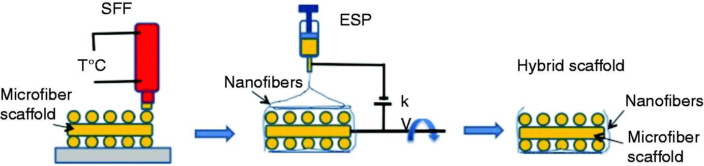
Production of supporting microfibre PCL scaffolds by a SFF
The microfibre scaffolds (Ø 6.4 mm × 1 mm) were made of PCL (the number average molecular weight Mn ca. 80,000; Sigma-Aldrich, Poznań, Poland) using SFF (BioScaffolder System; SysEng, Hünxe, Germany) according to the method described by Swieszkowski et al. 13 Although the melting point of PCL is ca. +60℃, the processing temperature was set to 95 ± 5℃ to properly extrude polymer melt. The polymer melt was extruded out through a 25-gauge needle (Ø = 250 µm) by an auger screw rotating with a speed of 250 rpm and using an air pressure of 8 bars. The designed strand distance was 600 µm. The lay-down patterns of 0/60/120° or 0/90° were programmed to form scaffolds with honeycomb-like patterns containing triangular or square macropores.
Preparation of spinning solutions
Polyethylene oxide (PEO; Sigma-Aldrich, Seelze, Germany) was used as a carrier polymer. Two water solutions, 2 % chitosan (type FG-90, medical grade, Mw = 346.0 kD, DD = 82.2%, ash content 0.28% heavy metal content 0.02%; Primex ehf, Siglufjordur, Iceland), in 1% dilute acetic acid with 1% of nonionic surfactant Triton X10019 and 2–5% PEO (6 × 10⁵ to 4 × 10⁶ g/mol) in water were mixed to obtain different chitosan-to-PEO mass ratios. Spinning solutions were characterized by the measurement of the dynamic viscosity (Brookfield Viscometer, Middleboro, MA, USA) and the surface tension using a stalagmometric method. Preparation of spinning solutions and assess their parameters were carried out at a temperature of 20–22℃ without humidity control. Only chitosan was weighted after its conditioning at 65% humidity. Due to the presence of well-conductive dilute acetic acid in the spinning solutions, their electrical conductivities were not measured.
ESP technique
All flat nanofibre scaffolds were manufactured based on two different stations (A and B) for ESP
20
(Figure 2). Station A – allows for quick start-up ESP and easy sampling. Hence usually was used to determine the relevant process parameters. In particular, after suitable modification, as described in A hybrid PCL-grate support covered with a chitosan/PEO composite nanofibre sheet section, it was used for the direct implementation of the nanofibrous seal coating on the PCL-grates. Station B – allows ESP (while maintaining the parameters established in advance on the A) nano/microfibrous mats uniform thickness and large area. Often, the manufacturing process takes several hours. The resultant coating is suitable on investigation according to the standards for evaluation for the nonwoven textile and other methods. It can serve as a substrate for cell culture, part of the dressing, scaffold, composite, etc. Most of the ESP experiments were carried out in laboratory conditions with the room and spinning liquid temperatures being 20–22℃ and the relative humidity ca. 65%. In some experiments, the temperatures of both the room and spinning liquid were increased to 32–35℃. In the room temperature experiments, 0.3 µm nanofibres and 7 µm microfibres were produced, whereas at 32–35℃ homogenous, 0.3 µm nanofibres were produced. The spinning liquid for ESP performed at 32–35℃ needs a sufficiently high viscosity, which was adjusted by the use of PEO with a high enough molecular weight.
A scheme of two different electrospinning stations. Station A is based on an immovable stand and station B on a rotating tube. 1 – An electrospinning multijet head; 2 – a set-up stand; 3 – a movable stand; 4 – an aluminium foil; 5 – a rotating tube; 6 – a high voltage power supply; 7 – a peristaltic pump and 8 – an U-pipe water manometer. The arrows indicate ability to adjust (bold) or to move (thin).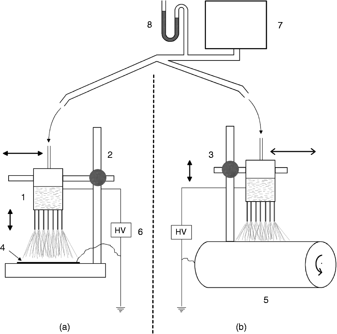
The station A is based on a stand made of electrically insulating materials, which do not move during the work phase. The stand is mounted on a plastic table and has a vertically movable arm for the adjustment of the height of the ESP head. An electrically grounded sheet of aluminium foil is placed on the table to fulfil the role of a collecting electrode. The ESP head is connected to high voltage (ES50P-20W; Ormond Beach, FL, USA), which was typically 20 kV. In most cases, the distance between the bottom of the spinning head and the aluminium collecting electrode was 20 cm and the max spinning area was 20 cm × 20 cm. The system is equipped with a small peristaltic pump, which creates air pressure to crowd the spinning liquid from the spinning head. The pressure was controlled by a U-pipe manometer with water and was always less than 4 cm H2O.
The station B is based on a grounded rotating tube, which is covered with a sheet of thin aluminium foil as a collecting electrode. The ESP head is clamped to a stand, which moves back and forth along the track along the rotating tube, on a fixed distance over it. The rotating velocity was usually 10 rpm and the ESP head speed was 2 cm/min.
Induction of water resistance of the chitosan/PEO nanofibres
The fresh electrospun composite nanofibres produced from a blend of chitosan and PEO are not ready to use because they are unstable in water. Chitosan/PEO nanofibres were cross-linked in open jars in hermetic chambers in 25% water solution of glutaraldehyde for 24 h at 22℃ to induce water resistance. Shorter time of cross-linking did not prevent transformation of the nanofibre sheet to a gel in water. Glutaraldehyde-mediated cross-linking may leave free and harmful aldehyde groups inside the nanofibres. Chemical neutralization of the free aldehyde groups was carried out using a water solution of glycine. Based on literature, 0.1 N glycine in water is enough for neutralization of the aldehyde groups, 21 but we used 10 times greater 1 N concentrations, usually for 6 h. Drying the chitosan-containing fibrous materials may lead to problems in maintaining the flatness and continuity of the sheet, hence various drying procedures, described in Chitosan/PEO composite nanofibre sheets section, were tested.
Nanofibre sheets were tested for the fibre size, sheet thickness, surface mass, apparent density, elongation at break at maximum tension, tensile strength, bursting strength (multidirectional strength, ball perforation), bending rigidity and structural resistance to handling of the sheets in water and air. Some of them were estimated according to the following standards: Tensile strength and elongation at break – BS EN 29073-3:1994, thickness – BS EN ISO 9073-2:2002, surface mass – BS EN 29073-1:1994, apparent density – calculated by dividing the mass of the sample surface by the thickness, bending rigidity – PN-73/P-04631 and bursting strength – PN-79/P-04738. The last more commonly known as the EN ISO 9073-5:2008 ‘Determination of resistance to mechanical penetration (ball burst procedure)’ determines the resistance to mechanical penetration of nonwoven fabrics. This standard specifies a method for determination of multidirectional strength of nonwoven and is carried out based on measurement force needed to nonwoven perforation by ball moving with constant velocity. At the first three Instron 5540 tensile testing machine was used.
Sterilization
All implant scaffolds used in this study were sterilized with gamma radiation (total dose 27 ± 3 kGy) prior to cell culture in the Laboratory of Radiochemistry, Department of Chemistry, University of Helsinki, Finland.
Cell culture
Poietics™ Human MSC (Lonza Walkersville Inc., Walkdersville, MD, USA) were cultured in MSCGM media (PT-3001, Lonza Walkersville Inc.) to confluence. Seeding density was 5–6 × 10³/cm2 and cells were refreshed 2–3 × per week. For detachment, 0.25% trypsin in PBS-EDTA was used and after centrifugation 600 g for 5 min cells were counted with Z1 Coulter Particle Counter (Beckman Coulter, Fullerton, CA, USA) with the window set to 6–24 µm.
For chondrogenesis, 10 ng/ml recombinant human transforming growth factor β3 (243-B3; R&D Systems, Minneapolis, MN, USA or produced in house) was used as a required stimulant in chondrogenic differentiation media (PT-3003; Lonza Walkersville Inc.). The hMSC chondrogenic differentiation medium is offered as a BulletKit™ including serum containing medium with the necessary supplements and growth factors (dexamethasone, ascorbate, insulin, sodium pyruvate, proline and
For messenger RNA (mRNA) and histochemical analysis MSCs were also cultured with and without chitosan/PEO fibre sheet in 16-well Chamber Slides as above, 2.5 × 10⁵ cells/well. Cells were seeded at day 0, allowed to attach and time points 1, 7, 14, 21 and 28 days were collected for RNA extraction and day 28 fixed for histochemistry. Each culture was done at least three times.
Histochemistry
Cells on TE construct were stained with 1% toluidine blue in acetate-HCl buffer (pH ∼ 2). Cells on chitosan/PEO fibre sheet were stained with nuclear 4′,6-diamidino-2-phenylindole (DAPI) stain and were inspected under ultraviolet or bright field using Olympus AX70 microscope (Olympus Corp., Tokyo, Japan). Images were acquired with a 12-bit CD camera (PCO CCD; SensiCam, Kelheim, Germany) and analysed using a semiautomatic AnalySis Pro 3.0 image analysis and processing software (Soft Analysis System GmbH, Münster, Germany).
Thin 3–6 µm historesin slices of TE constructs were deparaffinized and rehydrated. Antigen retrieval was performed at 37℃ in 4 mg/ml pepsin in 0.1 M HCl for 45 min or at 98℃ in 0.01 M sodium citrate pH 6.0 in Micromed T/T Mega Laboratory Microwave System (Milestone, Sorisole, Italy) using a specific retrieval program, followed by cooling down at 22℃ for 20 min. Slides were rinsed in dH2O, washed in PBS and incubated in (1) 1% H2O2 in PBS for 15 min to block the endogenous peroxidase; (2) 10% normal goat serum (Vector Laboratories, Burlingame, CA) for 1 h; (3) rabbit anticollagen type II (Cedarlane, Ontario, Canada) or nonimmune rabbit IgG (R&D Systems) 1:50 in 0.1% BSA-PBS overnight at 4℃; (4) biotin-conjugated goat anti-rabbit IgG antibodies (Vector Laboratories; 1:200 in 0.1% BSA-PBS for 1 h and (5) avidin–biotin–peroxidase complex (ABC complex, 1:200 in dH2O, Vector Laboratories) for 1 and 6 h in 0.006% H2O2 substrate and 3,3-diaminobenzidine chromogen solution (Sigmafast™ tablets; Sigma-Aldrich, Seelze, Germany) for 10 min. Slides were counterstained in hematoxyline, air dried and mounted in Mountex (HistoLab, Gothenburg, Sweden). Slides were analysed and photographed using Leica DM6000 microscope and 5 megapixel Leica DFC420 digital camera (Leica Microsystems) and images were analysed using a Leica Microsystems LAS AF application (Leica).
Quantitative real-time polymerase chain reaction
Primers used in quantitative real-time polymerase chain reaction (qRT-PCR).
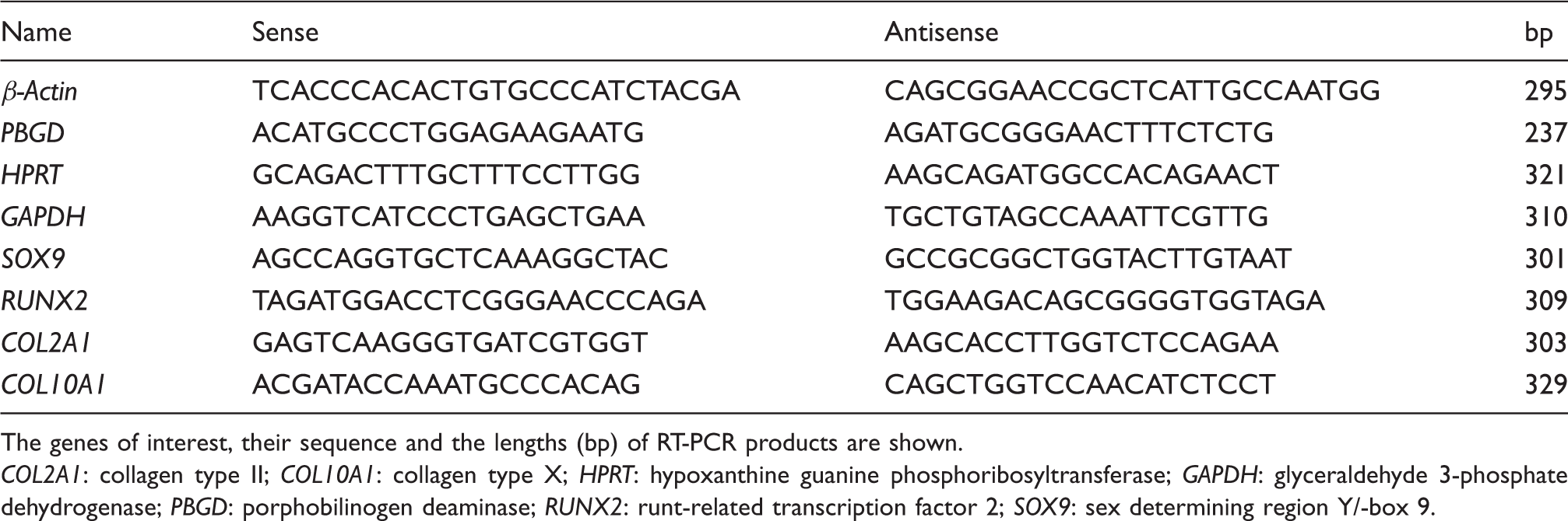
The genes of interest, their sequence and the lengths (bp) of RT-PCR products are shown.
COL2A1: collagen type II; COL10A1: collagen type X; HPRT: hypoxanthine guanine phosphoribosyltransferase; GAPDH: glyceraldehyde 3-phosphate dehydrogenase; PBGD: porphobilinogen deaminase; RUNX2: runt-related transcription factor 2; SOX9: sex determining region Y/-box 9.
Results and discussion
Chitosan/PEO composite nanofibre sheets
Fragile and flat nanofibre sheets were electrospun on collectors or directly on thicker and mechanically more durable supporting PCL-grate supports. Nanofibre sheets were used to seal the large pores (cellular sinks) and to provide a collagen nanofibre mimic growth platform composed of chitosan/PEO nanofibres. This arrangement enabled convenient manipulation and handling both of the single nanofibre sheets and of the nanofibre sheets at the top of the monolayer hybrid scaffolds during various physical, chemical and cellular treatments. The thin chitosan/PEO nanofibre sheets were produced in a multistep process consisting of preparation of the spinning solution, ESP, preparation of sheets of appropriate size, thickness and mesh size, cross-linking of the nanofibres with glutaraldehyde, soaking in an aqueous solution of glycine, plasticizing with glycerine, drying and trimming. The chitosan/PEO nanofibre sheets produced were water resistant, nontoxic, plastic and cell friendly. For achieving all these features for chitosan nanofibrous materials, it is not yet possible to obtain in a simple one-step process, for example by ESP alone. ESP from solutions of chitosan could be done with use of concentrated trifluoroacetic acid, TFA 22 or mixture TFA/dichloromethane, 23 which are spinnable and in these cases the help of PEO as a carrier polymer would not be necessary. However, chitosan fibres obtained in this way are unstable in water and require further treatment as the fibres of chitosan/PEO, or similar. For example we have used those efficiently in our practice treating them in a properly prepared alkaline environment. Moreover, the solvents are chemically aggressive and quickly cause major molecular degradation of chitosan, which leads to instability of spinning solutions over time and decreases the quality of polymeric material in fibres.
It should be emphasized that all the steps up to drying were optimized. Water-acid chitosan solution has no spinning ability in the ESP sense. PEO was very suitable as a carrier polymer because it is a water-soluble polymer available in a very wide molecular mass range and because it can be used in medical applications to adjust the viscosity of the spinning solution. Final chitosan-to-PEO mass ratios 80:20 and 60:40 worked best in our experiments. The dynamic viscosity of these spinning solutions was 376–486 cP. Use of the nonionic Triton X100 surfactant19,24 (applicable for medical purposes) additive in the spinning solution decreased the surface tension almost to half (from 85 to 41–46 dyne/cm), which greatly improved spinnability. This latter modification practically omits the formation of beads in spun fibrous material, which are usually caused by too high surface tension of the spinning solution. The use of the surfactant in an amount of 1% by weight on the solution is sufficient and by increasing its share to the level of 2–3% by weight does not lead to a visible change (scanning electron microscopy [SEM] studies) in quality of spun material. This ingredient is probably almost entirely removed from the material of the fibres during further water processing as a low molecular weight substance with excellent solubility in water. At 20–22℃ two modal fibres structures, nanofibres with diameter about 0.3 µm and microfibres with diameter about 7 µm (and single larger objects) were produced (Figure 3(a) and (a1)). Use of a slightly raised temperature up to 32–35℃ allowed preparing of uniform nanofibres with an average diameter of 0.33 µm (Figure 3(b) and (b1)). It seems that producing non defective nanofibrous mats from the ESP process is favourable as a substrate for living cells. A significant improvement in fibre quality using ESP chitosan nanofibres from solutions of chitosan/PEO is obtained also in other studies,
25
using even higher temperatures up to 80℃. Crosslinking of chitosan/PEO fibres in glutaraldehyde pairs for 24 h, as described in Cell culture on TE construct section, gave them stability in water. It can be expected that crosslinking increases the mechanical strength of chitosan fibres, but also lose a bit of its flexibility (their elongation during stretching should be lower). Therefore, the crosslinking process should be carried out to obtain sufficient resistance of a fibre to water, but not long, because the fibres become brittle. Due to the fact that the obtained fibrous material before the crosslinking in the present study is only a transitional form and might even damage when in contact with human skin, their mechanical tests were not performed. Therefore, a comparison of the mechanical properties of cross-linking chitosan fibres before and after cross-linking is not currently possible. Cross-linked fibres do not dissolve in water and they are not transformed into a gel in noticeably way. This means that the fibres after treatment with water and drying retain its shape during the microscopic observation of SEM. This resistance was checked for fibrous materials treated in aqueous medium for 5 days. At this time, samples were taken, dried and observed in the scanning electron microscope. In case of too weak cross-linking, the fibres were blurry shapes or even they cannot be distinguished from the background of the polymer. Detoxification of the aldehyde residues were done in an aqueous solution using glycine. During the glycine bath, up to half of noncrosslinked PEO, only used as an additive to facilitate ESP, leached out making the final chitosan/PEO nanofibres richer in chitosan. PEO leaching process was monitored qualitatively by analysing the thermal decomposition of chitosan/PEO samples by thermogravimetric analysis and quantified by Kjeldahl nitrogen content method. It has been found that the process is effective only for the first two hours and then (several days) run very slowly. Thus, it was assumed that an attempt to completely remove the PEO to see only chitosan fibres under these conditions is not possible.
Scanning electron microscopy (SEM) images of fibrous sheets produced from chitosan/PEO blend with a weight ratio of 60:40 by electrospinning at different temperatures: (a) electrospinning at +20℃ produced a bimodal distribution of the fibre diameters (a1), corresponding to the both kinds of fibres, nanofibres and microfibres as indicated by the arrows, and (b) Electrospinning at +32℃ produced only nanofibres (b1).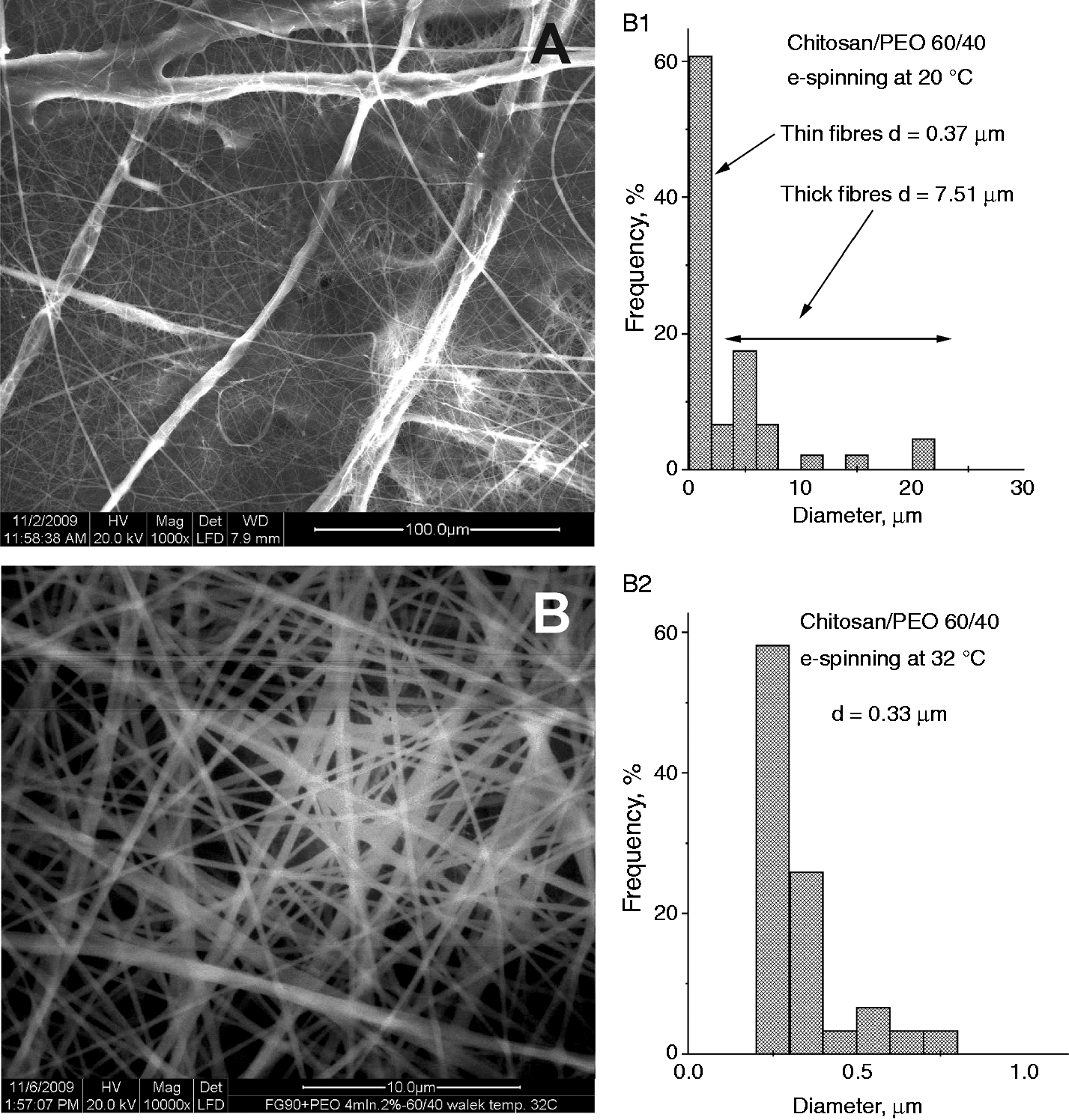
Physicomechanical properties of nanofibrous sheets produced from a chitosan/PEO 60/40 blend and cross-linked with glutaraldehyde.
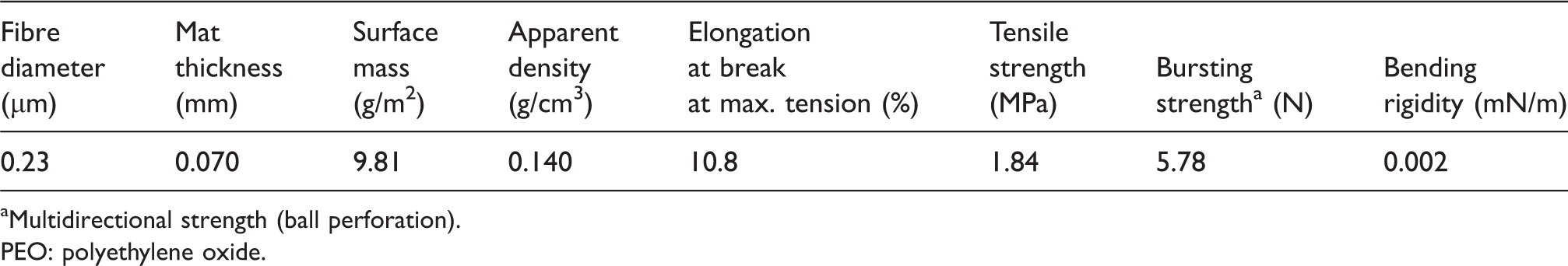
Multidirectional strength (ball perforation).
PEO: polyethylene oxide.
With respect to the strength of the current nanofibrous sheets, it can be noted, that the filamentous nanofibre components are much thinner that those required for conventional textiles, used, for example to implantable vascular grafts. However, currently manufactured nanofibrous materials form the substrate for cell growth and act as two-way, cell-tight sealing element, and will therefore not be exposed to high and pulsating hydrostatic pressure and shear stress that affect the vascular prostheses. These properties, together with the supporting PCL-grate support, protect the nanofibrous sheets from breakdown and disintegration during various manual operations.
Currently produced nanofibre chitosan/PEO composites sheets are very flexible in a high humidity. A sample sheet can be submerged in water in a Petri dish (Figure 4(a)). Multiple transfer of the samples, by picking them up to air and submerging them back in water do not cause any visible damage (Figure 4(b)). However, drying of the material sheet to an air-dry state leads to varying surface deformations and often to an irreversible damage in the form of cracks (Figure 4(c)).
Photographs of fibrous sheets produced of chitosan/PEO nanofibres using a 60:40 starting weight ratio and subjected to the following treatments: (a) submersed in water in a Petri dish; (b) lifted from the water (and lowered back several times); (c) dried to an air-dry state; and (d) saturated with glycerine and packaged between polyester meshes for handling. All samples have similar sizes. The white dots visible in (a) and (b) are air bubbles.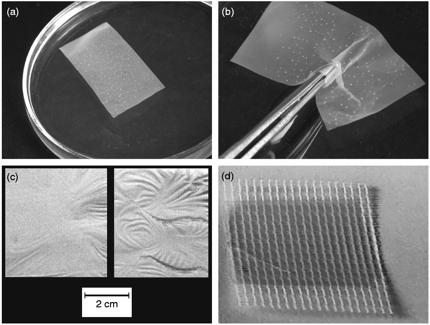
Tests were carried out to modify the drying process of nanofibrous scaffolds to reduce their accidental deformation and disintegration upon handling. These modifications consisted of reduction of the rate of drying, gradual replacement of water by ethyl alcohol and then drying of the ethanol and freeze-drying. Such methods of drying noticeably improved the resistance of the samples against mechanical damage, which still was not fully satisfactory. It should be noted that deformations resulting from a considerable shrinkage of the fibre sheets during the drying process are characteristic for many materials made from polymers of natural origin and characterized by a high absorption of moisture. Hence, their use often requires the development of an appropriate finishing process. Regarding the plasticizer, it was found that the best results were obtained using 40 wt% glycerine. In addition, glycerine retains water. Thus, glycerine-treated nanofibrous sheets retained the same flexibility state as they had in high humidity and were resistant to handling stress and deformations (Figure 4(d)). However, use of this brand of chitosan/PEO nanofibrous sheet was still somewhat problematic because glycerine impaired the initial sticking to and facilitated the subsequent detachment of the nanofibrous chitosan/PEO sheets from the surface of the supporting macrofibre PCL-grate support. Hence, in addition to production of single, flat nanofibrous sheets, an attempt was made to use the ability of ESP technique to directly cover the carrier element, the PCL-grate support, with chitosan/PEO nanofibres as a sealant coating. This procedure is shortly described below.
A hybrid PCL-grate support covered with a chitosan/PEO composite nanofibre sheet
To produce a sealing chitosan/PEO composite nanofibre sheet directly on PCL-grates (pretreated with and without electro conducting surfactant) by ESP required attachment of the PCL-grate to a copper wire using hot gluing with a molten PCL granule (Figure 5(a)). The lay-down patterns of 0/60/120° and 0/90° PCL-grates were made of microfibres with a diameter of about 300 ± 35 µm. The maximum size of the pores of the PCL-grates was about 350 ± 50 µm. Copper wire-PCL constructs were mounted on electro conducting cantilevers (Figure 5(b)), which could be rotated in the ESP space during nanofibre coating. After unmounting from the ESP apparatus and removal of the copper wire, the central part of the nanofibre sheet was cut off from the bottom of the PCL-grate (Figure 5(c)), while the nanofibre sheet (coating) on the cell seeding face of the implant was retained on the top of it (Figure 5(d)). Cells were seeded from this side of the scaffolds into the triangular or square macro pores formed between the PCL-microfibres arranged in a honeycomb-like patterns. Cells were at the bottom of the macro pores retained by the sealing chitosan/PEO nanofibre sheet. These scaffolds were then used in the actual and final chondrogenic experiments (after numerous pilots done).
Photographs of the manufacture of scaffolds based on thick supporting PCL-grates, coated with a sealing nanofibrous sheet composed of chitosan/PEO, produced directly on the PCL targets by electrospinning. (a) a PCL-grate is hot-glued with a drop of molten PCL to a copper wire; (b) scaffolds have been mounted in a conductive cantilever and then located in the zone of electrospinning for direct coating with nanofibres; (c and d), respectively, show the uncovered bottom and the sealed cell seeding top of the scaffold.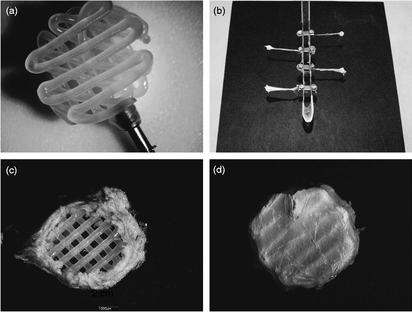
MSC cultures on chitosan/PEO nanofibre sheet
MSCs cultured on chitosan/PEO fibre sheet in a chondrogenic induction medium formed spontaneously aggregates within 24 h (Figure 6). These aggregates remind the chondrogenic pellets, which are normally formed when pelleting is used to establish cell-to-cell contacts to promote chondrogenesis.
26
Initial differentiation of mesenchymal stem cells cultured in a chondrogenic induction medium on chitosan/PEO fibre sheet. (a) Fluorescence of nuclei in a 4′,6-diamidino-2-phenylindole (DAPI) staining and (b) morphology of a cell pellet in a bright field microscopy. Scale bar 100 µm.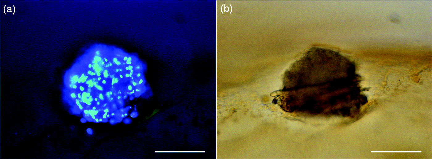
Analysis of chondrocyte markers during chondrogenesis
Quantitative real-time PCR analysis confirmed a successful induction and progression of chondrogenesis of human bone marrow-derived MSCs cultured in the chondrogenic induction medium on chitosan/PEO fibre sheets, but lack of such differentiation upon culture on regular cell culture plastics. On chitosan/PEO sheet early chondrocyte markers SOX9 (day 21, p = 0.037 to day 0) and RUNX2 (day 7, p = 0.008 to day 0) are first induced in succession, followed by a continuously increasing cartilage-specific matrix protein collagen type II expression, which is higher than without chitosan/PEO sheets (day 21 and 28, p = 0.032).
18
Supporting chondrogenesis, the expression of collagen type X is diminished and maintained low, suggesting prevention of chondrocyte hyperthrophy and osteogenesis (Figure 7(a)).
27
In contrast, the regulated flow of events is lost in MSC cultured on regular cell culture plastics, with only a transient and short peak of collagen type II expression, but without subsequent progression, highly increased collagen type X expression (day 7, p = 0.029 and day 29, p = 0.043 to chitosan/PEO), suggesting transition of the chondrogenesis to osteogenesis (Figure 7(b)).
Messenger RNA expression of chondrogenic differentiation markers in (a) differentiating stem cells growing on chitosan/PEO fibre sheet or (b) without fibre sheet. Relative expression to day zero.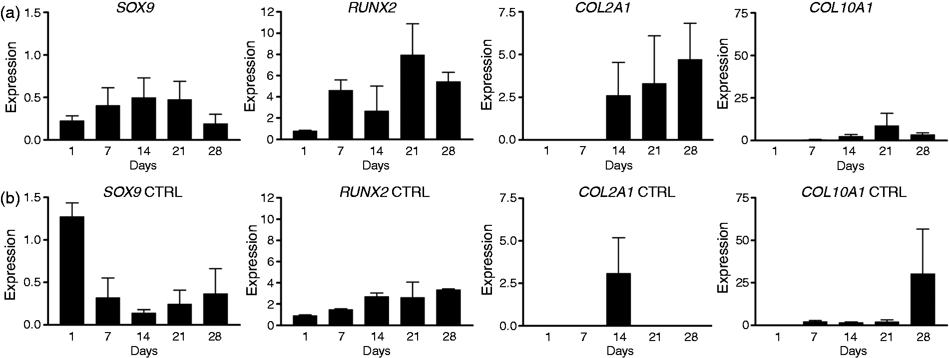
Cell culture on TE construct
Final 3D-TE constructs were formed by piling up three MSC seeded and precultured 2D-monolayers, composed of the PCL-grate support and an overlying (directly electrospun) chitosan/PEO nanofibre sheet scaffolds.
Such 3D-TE constructs were cut to 4–20-µm thick sections with a regular histological microtome and stained with toluidine blue, which allows examination of the TE construct structure, but also of the TE morphology inside the lasagne scaffolds, e.g. cartilage proteins proteoglycan and collagen (Figure 8(a)).
28
At culture day 28 such 3D-TE constructs contained chondrocytes in cartilage matrix, located already isolated in their lacunae (Figure 8(b) and (c)).
29
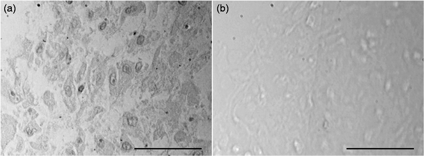
Although the cartilage was still relatively hypercellular, these MSC-produced chondrocytes produce type II collagen-rich matrix as was shown in immunostaining (Figure 9(a)), with a negative control staining using normal rabbit IgG at the same concentration as and instead of the specific primary antibodies confirming the specificity of the staining (Figure 9(b)).
(a) A vertical section of a 3D-tissue engineering (TE) construct showing here three PCL layers of the support grate. (b) Stem cells undergo chondrogenic differentiation inside the TE construct and (c) a higher magnification shows already a typical lacuna-like structure with a chondrocyte, surrounded by cartilaginous matrix. Scale bar in panel a 500 µm and in panel b 20 µm. Immunohistochemical staining of (a) extracellular matrix collagen type II and (b) control nonimmune IgG of differentiated cells inside the tissue engineering construct. Scale bar 50 µm.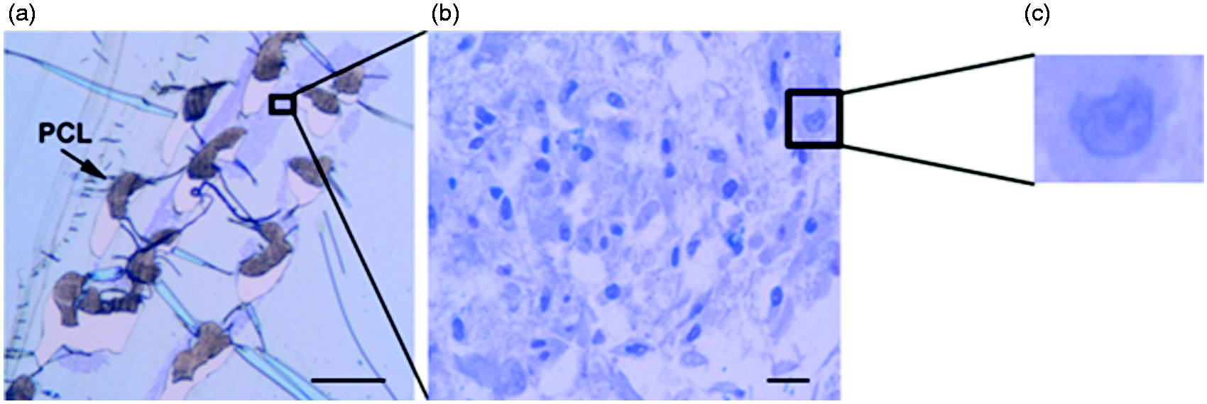
The principles of regenerative medicine, 30 use of MSC in regenerative medicine and TE applications 31 and this particular approach in chondrogenesis 6 have been reviewed in some detail in a series of articles. The current chondrogenic approach has considerable commercial potential, as is suggested by the success of ACI with a periosteal or collagen membrane, the second-generation MACI and the third-generation 3D matrix assisted TE approaches. 32 To approach and reach this goal, intimate co-operation between material, physical and medical scientists is necessary.
Our intention was to study the biocompatibility of 3D composite scaffolds made of structurally supporting micron-size fibres to attain mechanical strength and good handling properties and of collagen fibre mimicking nanofibre sheets to attain a good growth and differentiation potential. The function of the last mentioned nanofibrous sheet is twofold. First, it provides a culture substrate platform for the seeded cells for differentiation and matrix synthesis. Second, the sealing 2D nanofibre sheets in the 3D-TE constructs prevent detachment and escape of the MSCs, cellular aggregates, chondrogenic cells and of the forming cartilage. In particular, sealing nanofibrous sheets prevent capture of the scaffold by the in-growth of the rapidly migrating, proliferating and scar tissue forming fibroblasts. This is necessary because chondrogenesis from MSCs and synthesis of the cartilage matrix by already differentiated cells are slow processes. Full cartilage regeneration requires therefore time. In deep and superficial cartilage lesions there is a tendency that fibrocartilaginous tissue at a rapid pace fills the cartilage tissue defects produced by traumatic or arthritic cartilage lesions, thus preventing any subsequent attempts to replace the defect area with the original tissue, with the truly hyaline articular cartilage.
One of the challenges was to transfer the MSC-to-chondrocyte differentiation from the cellular pellets to TE scaffolds, but this was possible with the use of 3D PCL-chitosan/PEO hybrid scaffolds and human bone marrow-derived MSCs. It was particularly important to demonstrate that chondrogenesis, from the early cellular pelleting and initial cell–cell contact phase could progress to chondrocytic differentiation and subsequent synthesis of the cartilage matrix in lasagne-type, multilayer implants. One of the advantages of this lasagne-type assembly of tissue engineered monolayers is that the slowly migrating cells do not need to intrude to the superficial pores and then further through the interconnected pores deeper into the centre of the bulky implant. Cells are seeded separately on the monolayer constructs, which are tough and easy to pile up, one upon the other, into a multilayer. The energy required for the synthetic and migratory, haptotactic activities is saved and all the matrix of the TE construct is from the very beginning occupied by stem cells.
We launched the lasagne principle. As mentioned above, nanosize fibres support the chondro-inductive differentiation and protect against chondroptosis and matrix degradation, but also confine the cells to their own territorial domains, with ‘no way out’ (escape) for the repair cells but ‘no way in’ either for the scar forming fibroblasts (capture). Indeed, fibrocartilage is produced when the widely used mosaicplasty is used to ‘heal’ cartilage defects with a method, which leads to bleeding from the bone marrow and recruitment of endogenous bone marrow-derived MSCs but also of marrow fibroblasts, which then fill the defect with mechanically inferior (nonelastic) fibrocartilage.
No bioreactor was necessary because the cells, in spite of quite large TE construct volume in a membranous structure are never very far from oxygen and nutrients, which even the chondrocytes need for matrix synthesis and maintenance. Cells seeded in the 3D biomatrix were shown to remain alive and to develop a chondrocytic phenotype as a result of which they produce cartilage extracellular matrix.
In conclusion, a new 3D, multilayer PCL-chitosan/PEO prototype scaffold was produced, suitable for handling during preparation and processing, enabling seeding of 2D-scaffolds with cells and then an assembly of multilayer 3D-TE constructs for different size lesions but always with even distribution of the cells inside the TE-implant. Such biomaterial matrix supported both the initial and late phase of chondrogenesis.
Footnotes
Acknowledgements
We thank Tekes of Finland, Polish Ministry of Science and Higher Education and MOST (Ministry of Science and Technology, Israel) for financial support to BioNanoCoRe. We thank the Biomedicum Imaging Unit in University of Helsinki for providing the required imaging equipment and analyses. Erkki Hänninen and Eija Kaila are acknowledged for technical help.
Declaration of Conflicting Interests
The author(s) declared no potential conflicts of interest with respect to the research, authorship, and/or publication of this article.
Funding
The author(s) received the following financial support for the research, authorship, and/or publication of this article: This study was supported by HUS evo grant, Invalid Foundation, Finska Läkaresällskapet, Sigrid Jusélius Foundation, National Doctoral Program of Musculoskeletal Disorders and Biomaterials, Jane and Aatos Erkko Foundation, Center for International Mobility CIMO, Danish Council for the Strategic Research, Regenerative Medicine RNP of the European Science Foundation.