
Abstract
AISI 316L specimens were nitrided using a low temperature (390℃) plasma nitriding process and then coated with a thin layer of titanium nitride by closed field unbalanced magnetron sputtering. The microstructure, adhesion properties and hardness of the duplex-treated samples were examined using X-ray diffraction, scratch testing and nanoindentation, respectively. In addition, the tribological properties were investigated by means of reciprocating wear tests performed against 316L, Si3N4 and Ti6Al4V balls under a load of 10 N for 24 min in 0.9% NaCl solution. The electrochemical resistance of the samples was evaluated by potentiodynamic polarisation tests. Finally, the biocompatibility of the samples was investigated by seeding purified mouse leukemic monocyte macrophage cells (Raw 264.7) on the sample surface for one, three and five days, respectively. In general, the results showed that the duplex nitriding and titanium nitride coating process significantly improved the tribological properties, electrochemical resistance and biocompatibility of the AISI 316L samples.
Introduction
With improvements in medical science, the average human life expectancy has increased tremendously over the past century. However, an aging population brings with it many problems, among which one of the most challenging is that of developing effective surgical implant materials. Orthopaedic, cardiovascular and dental devices are traditionally fabricated of AISI 316L stainless steel due to its relatively low cost and ease of forming. 1 However, AISI 316L has poorer wear resistance than bioceramic materials such as Al2O3. 2 Moreover, AISI 316L has a lower corrosion resistance than alloys such as Ti6Al4V. 1 Consequently, its mechanical strength and biocompatibility are inevitably impaired. 3
Surface treatments are widely used throughout industry for applications such as cutting tools and mould tools.4–7 Many studies have shown the effectiveness of surface nitriding in improving the hardness and wear resistance of AISI 316L stainless steel.8–10 Similarly, titanium nitride (TiN) coatings deposited using the physical vapour deposition (PVD) technique have also been shown to improve the wear resistance11,12 and corrosion resistance.13–15 The authors16,17 showed that similar benefits can be obtained for AISI 316L by depositing the TiN film using an arc-plating process. In addition, several researchers have performed duplex surface treatments comprising surface nitriding followed by the PVD deposition of TiN coatings to improve the corrosion resistance18,19 and tribological properties 20 of AISI 316L components.
Besides their favourable mechanical and tribological properties, TiN coatings also have good biocompatibility. 21 For example, the deposition of TiN coatings on NiTi substrates inhibits the formation of toxic Ni2+, which is a carcinogen and has immune-sensitising effects. 22 As a result, TiN coatings have attracted increasing attention in recent years for biomedical applications such as orthopaedic implants, dental implants, and coronary stents.23–25
Although the tribological, electrochemical and biocompatibility properties of AISI 316L have attracted significant attention in the literature, previous studies generally consider just one particular aspect of the AISI 316L performance. By contrast, the present study performs a systematic investigation into all three properties of AISI 316L. The investigations focus particularly on the effects of a duplex surface treatment process consisting of plasma nitriding followed by TiN thin-film deposition. In general, the results confirm the effectiveness of the surface treatment process in improving the tribological, electrochemical and biocompatibility performance of AISI 316L.
Materials and methods
Materials and nitriding process
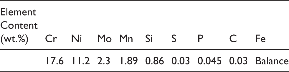
Chemical composition of AISI 316L.
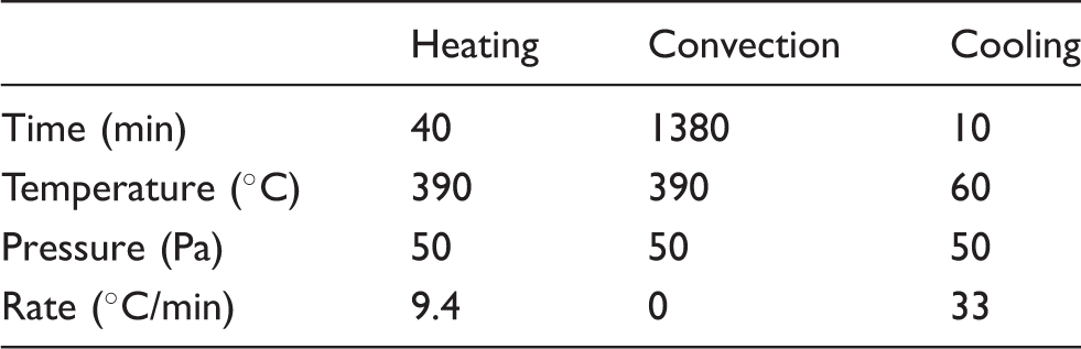
Plasma nitriding parameters for AISI 316L.
CFUBMS coating deposition
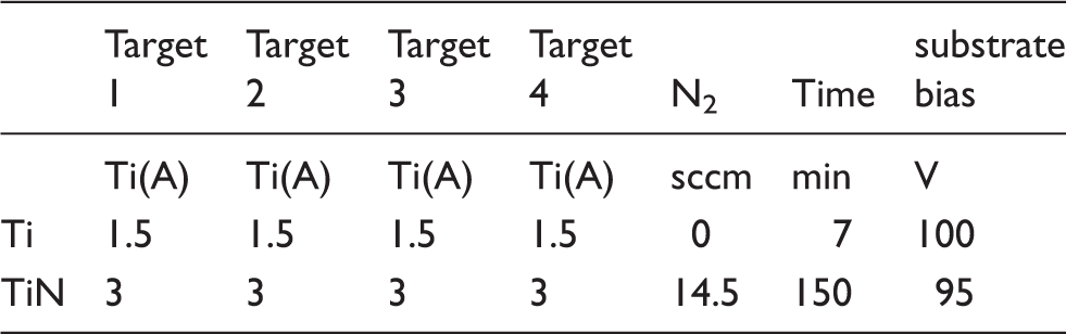
CFUMBS deposition parameters for TiN coating.
Structure and mechanical properties
The coating structures were examined using a multi-purpose X-ray thin-film diffractometer (XRD, Rigaku, Japan) with Cu-target Kα radiation, a glancing incident angle of 2°, an operating voltage of 40 kV, and an operating current of 100 mA. In analysing the structure, the scanning angle (2θ) was increased from 20° to 80° at a rate of 4°/min. The microstructures of the various samples were observed using an ultra-high resolution field emission scanning electron microscope (HR-FESEM, Carl Zeiss AURIGA, Germany) with a 5 kV accelerating voltage. The sample surfaces following wear testing, potentiodynamic testing and cell culturing were investigated using an environmental scanning electron microscope (ESEM, FEI Quanta 400 F, America) equipped with an energy dispersive spectrometer (EDS) operated at 10 kV. The surface roughness (Ra) was measured using an optical profilometer (WLI LAB, BMT, Germany). The hardness of the uncoated samples was measured using a micro hardness tester (HMV-2, Shimadzu, Japan) under a load of 25 g. By contrast, the hardness of the TiN-coated samples was measured using a nanoindenter (UNAT-M, Asmec, Germany) under a load of 35 mN. In both tests, the hardness was evaluated as the average value obtained over eight repeated measurements. The adhesive properties of the TiN-coated samples were measured using a scratch tester (FM-POD-200NT, Taiwan) fitted with a Rockwell-C indenter with a tip size of 300 µm. For each sample, the loading rate was set as 1 N/s, the maximum load as 100 N, and the scratch length as 10 mm. The critical load (Lc) was taken as the load at which the substrate first became visible at the base of the scratch trace. 30
Wear properties
The tribological properties of the treated and untreated samples were examined in point-contact mode using a reciprocating sliding wear tester (SRV, Optimol, Germany). The tests were performed in simulated body fluid (0.9 wt.% NaCl solution) against three different counterbodies, namely 316 L, Si3N4 and Ti6Al4V balls (each with a diameter of 10 mm). For each wear pair, the contact load was set as 10 N, the reciprocating frequency as 50 Hz, the stroke length as 1 mm, and the total sliding duration as 24 min. Each specimen was tested twice. Following each test, the average wear depth and wear rate of the wear scars on the specimen were determined using an optical profilometer (WLI LAB, BMT, Germany).
Electrochemical properties
The electrocorrosion resistance of the various samples was evaluated by means of potentiodynamic polarisation tests performed in 0.9 wt.% NaCl solution using a ECW-5000 potentiostat (Jiehan, Taiwan). Prior to testing, pure N2 was passed through the NaCl solution for 30 min to purge it of O2. The tests were performed using a three-electrode system consisting of a saturated calomel electrode (SCE) as the reference electrode, a platinum slice as the counter electrode, and the sample (with an exposed area of 1 cm2) as the working electrode. For each sample, the potential was increased from −1 V to 3 V at a rate of 2 mV/s. The corrosion potential and breakdown potential were obtained directly from the polarisation curves, with a higher corrosion potential and breakdown potential indicating an improved anti-corrosion performance. 31 The polarisation tests were repeated three times for each sample.
Wettability
The wettability of the treated and untreated samples was investigated using a contact angle meter system (FTA-1000B, First Ten Ångstroms, America). In performing the measurement process, deionised water (DI) was dripped onto the sample surface and the droplet image was captured continuously over a period of 10 s. The images were transferred to a screen and the contact angle was then measured automatically. The measurement process was repeated eight times for each sample. To ensure the reliability of the measurement results, the sample was cleaned ultrasonically in ethanol for 10 min and then air dried before each measurement process.
Cell viability
The samples were placed individually into a 24-well plate. Mouse leukemic monocyte macrophage cells (Raw 264.7) were added to a culturing medium (Dulbecco Modified Eagle’s Medium plus 10% Fetal Bovine Serum, 1% Penicillin/Streptomycin, 3.7 g/L sodium bicarbonate) with a concentration of approximately 10,000 cells per 2 ml solution, and the solution was then dripped onto each sample in the 24-well plate (5659 cells/cm2). The plate was cultured in a humidified incubator at 37℃ under a 5% CO2 atmosphere for one, three and five days, respectively. Following incubation, the cell viability of the samples was evaluated by means of a 3-(4,5-Dimethylthiazol-2-yl)-2,5-diphenyltetrazolium bromide (MTT) assay. Briefly, 50 mg MTT and phosphate-buffered saline (PBS) were formulated as a 10 ml MTT solution; 1 ml of MTT solution was added to each well for 2 h, and the MTT solution was then drained; 1 ml dimethyl sulfoxide (DMSO) was dripped into each drained well for a period of 30 min. Finally, 0.1 ml of solution was extracted from every well and distributed into a 96-well microplate fitted to a measuring platform. The optical density (OD) of each well was measured using a Synergy HTX Multi-Mode Reader (BioTek, America) with a wavelength of λ = 595 nm. The number of cells was then derived from the measured OD value in accordance with the formula Y = 398617X-16870, where Y and X are the cell number and OD value, respectively. The cell culture experiments were repeated three times for each specimen.
Results and discussion
Structure, hardness and coating adhesive properties
Figure 1(a) shows the XRD patterns of the original 316 L sample and nitrided N316 sample, respectively. The 316 L pattern contains prominent peaks corresponding to γ-Fe and CrO3 surface oxide, whereas that of the nitrided sample comprises peaks corresponding to CrN and S-phase (i.e. iron supersaturated with nitrogen). Figure 1(b) shows the XRD patterns of the TiN coating. The coating structure is dominated by a (111) orientation. However, (200), (220) and (311) orientation planes are also observed.
XRD patterns for (a) 316L and N316L samples, and (b) TiN coating on silicon.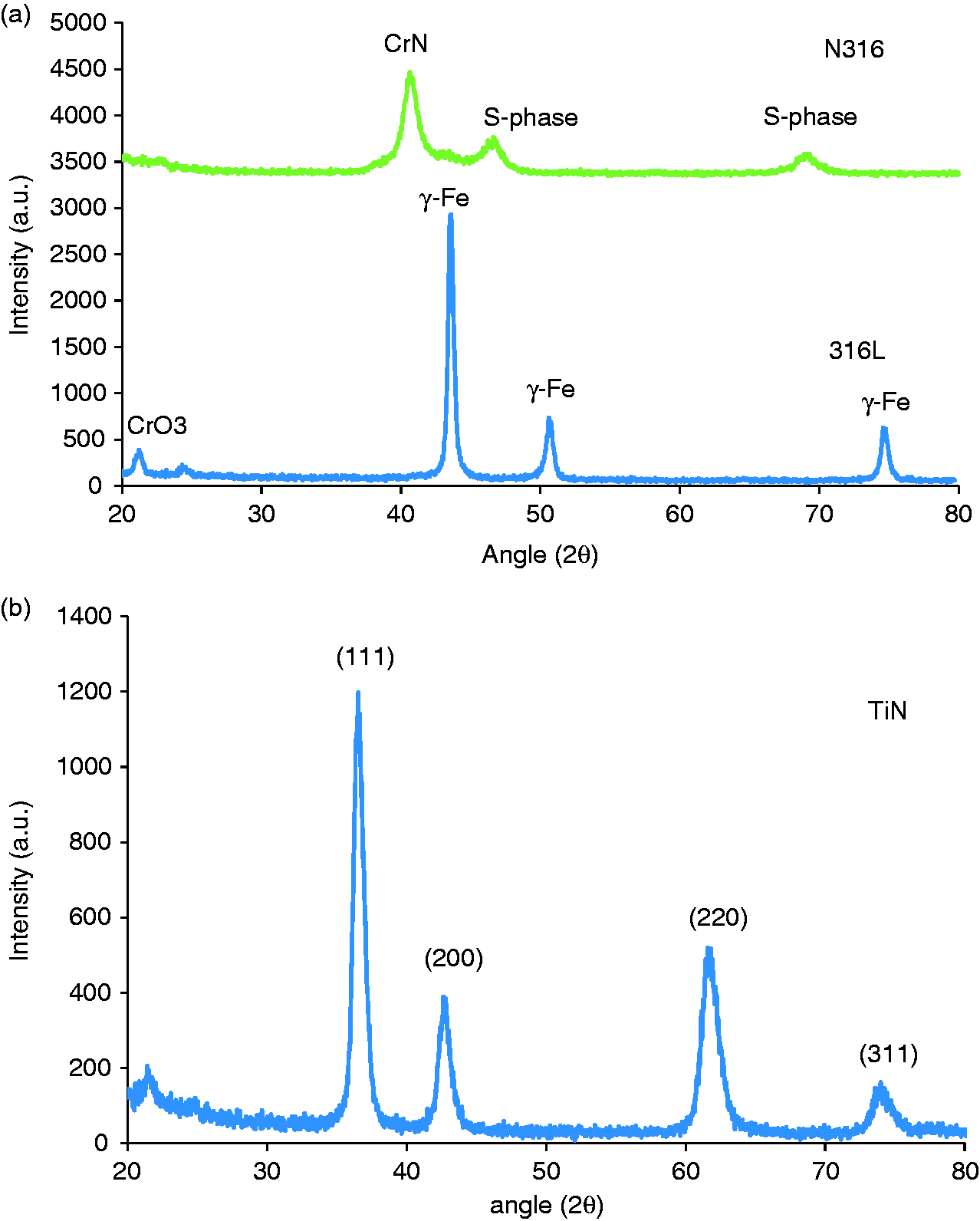
Figure 2(a) presents an SEM cross-sectional image of a TiN coating deposited on a Si wafer. Note that the coating is deposited using the same parameters as those shown in Table 3. It is seen that the coating has a thickness of approximately 1.7 µm and has an obvious columnar structure. Figure 2(b) presents a cross-sectional image of the TiN coating deposited on the N316 sample. It is observed that the coating and nitrided layer are separated by a well-defined boundary and the nitrided layer has a thickness of approximately 5 µm.
Cross-sectional SEM images of: (a) TiN coating on Si wafer, and (b) TiN-N316 sample.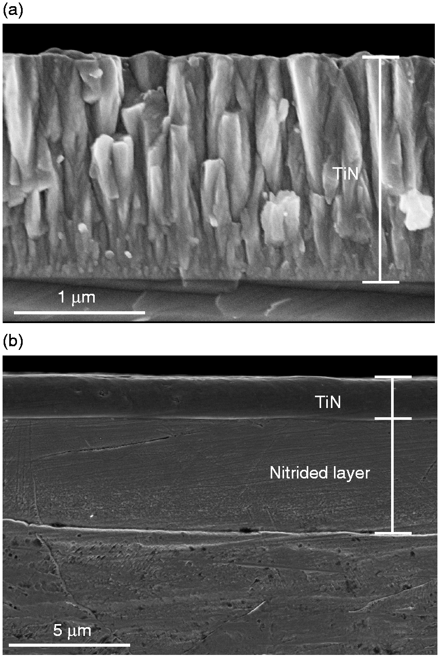
Hardness, surface roughness and adhesion properties of coated and uncoated samples.
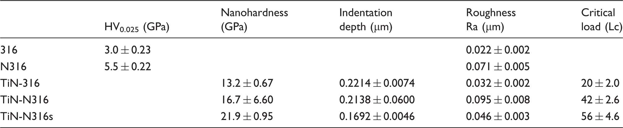
As shown in Table 4, the TiN coating deposited on the untreated 316 sample has a low critical load of 20 N (TiN-316). By contrast, the coatings deposited on the two nitrided samples have critical loads of 42 N (TiN-N316) and 56 N (TiN-N316s), respectively. Figure 3 presents SEM images of the scratch traces on the three TiN-coated samples. Note that the dark region in each image corresponds to residual TiN coating, while the white region corresponds to the exposed substrate. For the TiN-316 coating, many small cracks (white dots) are observed in and around the scratch trace, indicating that the coating has a relatively poor adhesion performance. As discussed above, the nitrided substrates have a greater hardness than the untreated sample. Consequently, they undergo less deformation under a given load. As a result, they provide a better (more uniform) support of the TiN coating, and hence the coating adhesion is improved (see Figs. 3(b) and 3(c), in which a greater amount of residual coating is observed in the scratch trace). Observing the results presented in Table 4, it is noted that the critical load of the nitrided samples increases with a decreasing surface roughness. In scratch tests, the tip experiences a lower contact stress when scraping across a smoother surface.
36
Thus, for a coated surface, the onset of coating fracture is delayed. As a result, the adhesion performance of the TiN-N316s sample (with a surface roughness of 0.046 µm) is better than that of the TiN-N316 sample (with a surface roughness of 0.095 µm).
Scratch traces on: (a) TiN-316, (b) TiN-N316 and (c) TiN-N316s samples. (Note that arrows show the onset of TiN coating rupture.)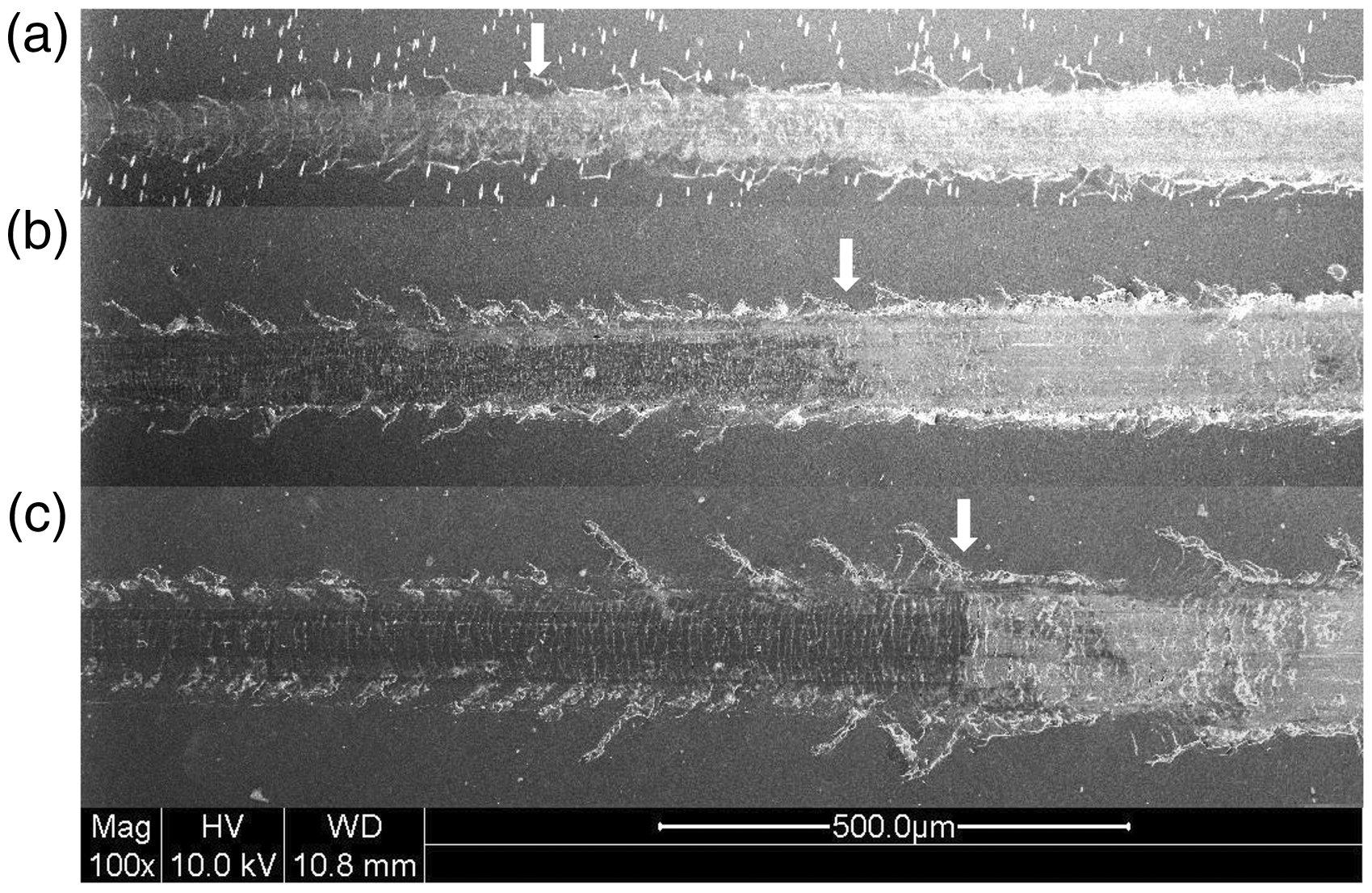
Tribological properties
Figure 4 shows the average coefficients of friction (COF) of the treated and untreated samples when sliding against the 316 L, Si3N4 and Ti6Al4V balls, respectively. For each counterbody, the TiN-coated samples have a lower COF than the uncoated samples. Moreover, of the coated samples, the TiN-N316s sample has the lowest COF (i.e., 0.59, 0.78 and 0.68 when sliding against the 316 L, Si3N4 and Ti6Al4V balls, respectively).
Average coefficients of friction of all samples when sliding against 316L, Si3N4 and Ti6Al4V balls under load of 10 N.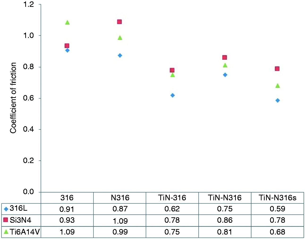
Figure 5 shows the wear depths of the various wear pairs. For the 316 sample, wear depths of 4.31 µm, 7.10 µm and 12.06 µm are observed when sliding against the 316 L, Si3N4 and Ti6Al4V counterbodies, respectively. Following the nitriding process, the substrate hardness increases from 3 GPa to 5.5 GPa (Table 4), and hence the wear depths of the N316 sample reduce to 2.5 µm, 5.6 µm and 7.11 µm, respectively. The TiN coatings yield a further increase in the surface hardness, and hence the wear depths of the TiN-316 sample are also reduced to 2.77 µm, 4.25 µm and 8.35 µm, respectively. Of the various coated samples, the TiN-316 sample has the lowest critical load (Table 4) and is hence most easily fractured during sliding. Therefore, it has a greater wear depth than either the TiN-N316 sample or the TiN-N316s sample. As discussed above, the duplex surface treatment (plasma nitriding followed by TiN coating deposition) increases both the surface hardness and the critical load. Consequently, the TiN-N316 and TiN-N316s samples both have an improved wear resistance. Of the two samples, the TiN-N316s sample has a higher surface hardness and a greater critical load. Thus, it offers a better wear resistance, i.e. wear depths of 1.19 µm, 2.06 µm and 5.65 µm, respectively, when sliding against the 316 L, Si3N4 and Ti6Al4V balls.
Average wear depths of all samples when sliding against 316L, Si3N4 and Ti6Al4V balls under load of 10 N.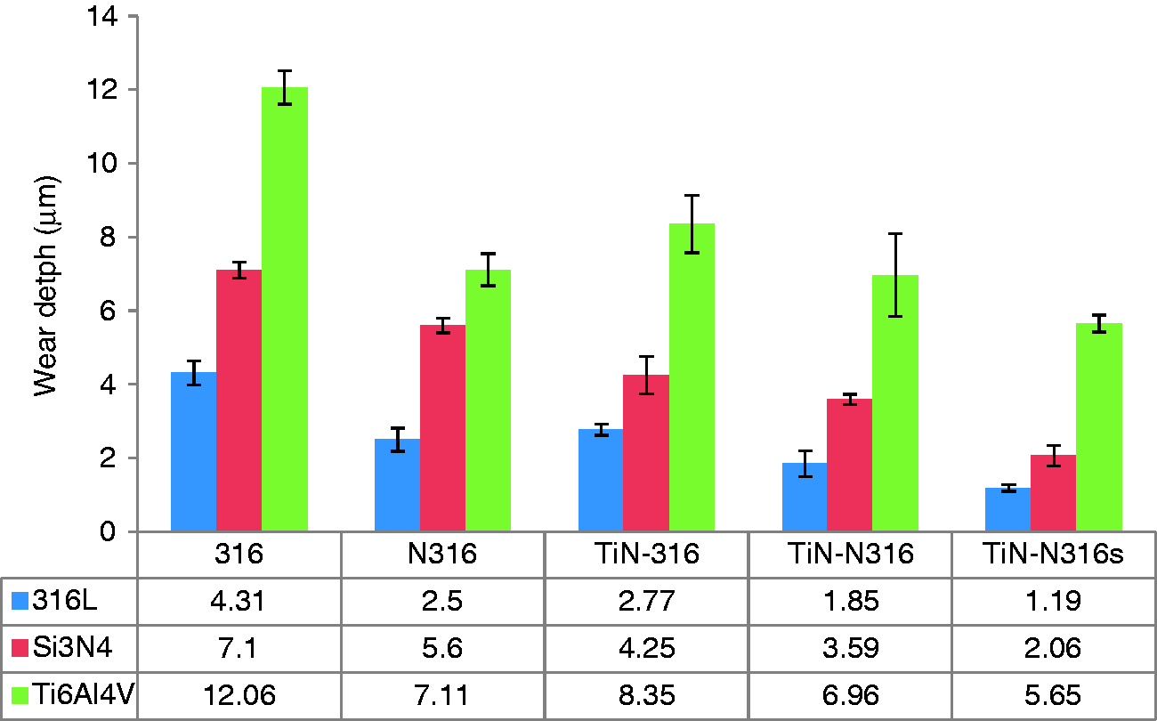
Figure 6 shows the wear rates of the treated and untreated samples. From inspection, the wear rates of the N316 sample are around 2, 1.3 and 2.6 times lower than that of the untreated 316 sample when sliding against the 316L, Si3N4 and Ti6Al4V balls, respectively. Furthermore, the wear rates of the TiN-N316s sample are 76, 10 and 3 times lower than that of the 316 sample when sliding against the three counterbodies.
Average wear rates of all samples when sliding against 316L, Si3N4 and Ti6Al4V balls under load of 10 N.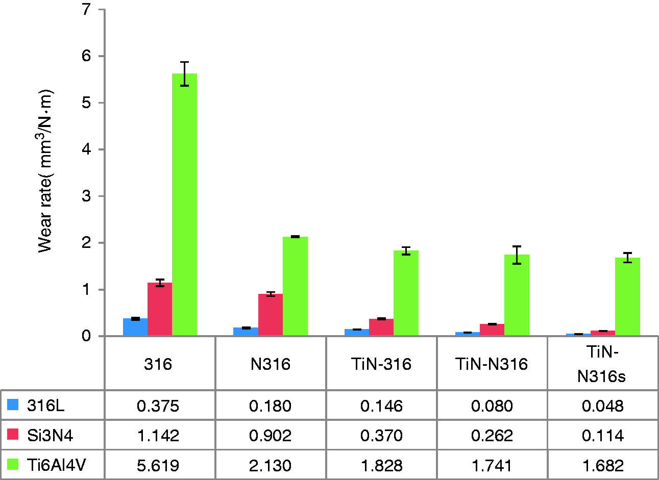
Overall, the results show that the duplex surface treatment (nitriding and TiN coating) yields an effective improvement in the wear resistance of the original 316L substrate due to an improved substrate hardness (and hence a better support of the coating) and an enhanced coating adhesion performance.
Figure 7 presents SEM images of the wear surfaces of the various samples following sliding against the 316L ball. As shown in Figure 7(a) and (b), the 316 sample contains obvious scratch marks and rough regions caused by adhesive wear. In other words, the wear mechanism is one of both abrasive wear and adhesive wear. The EDS analysis results show that the white-circled region labelled as #1 in Figure 7(b) (denoted as WC1 hereafter, and corresponding to the adhesive wear region of the surface) has an O content of 28.1 at%. By contrast, the white-circled region labelled as #2 (denoted as WC2 hereafter, and corresponding to the abrasive region of the surface) has an O content of just 11.4 at%. In other words, the oxidation effect due to adhesive wear is more significant than that due to abrasive wear.
Wear surfaces following sliding against 316L ball: (a) 316, (b) 316 (1000×), (c) N316, (d) N316 (1000×), (e) TiN-316, (f) TiN-316 (1000×), (g) TiN-N316, (h) TiN-N316 (1000×), (i) TiN-N316s, and (j) TiN-N316s (1000×). Note that (b), (d), (f), (h) and (j) show magnified views and compositions of marked regions in (a), (c), (e), (g) and (i), respectively. Note also that compositions of unworn surfaces are shown in (a), (c), (e), (g) and (i), respectively.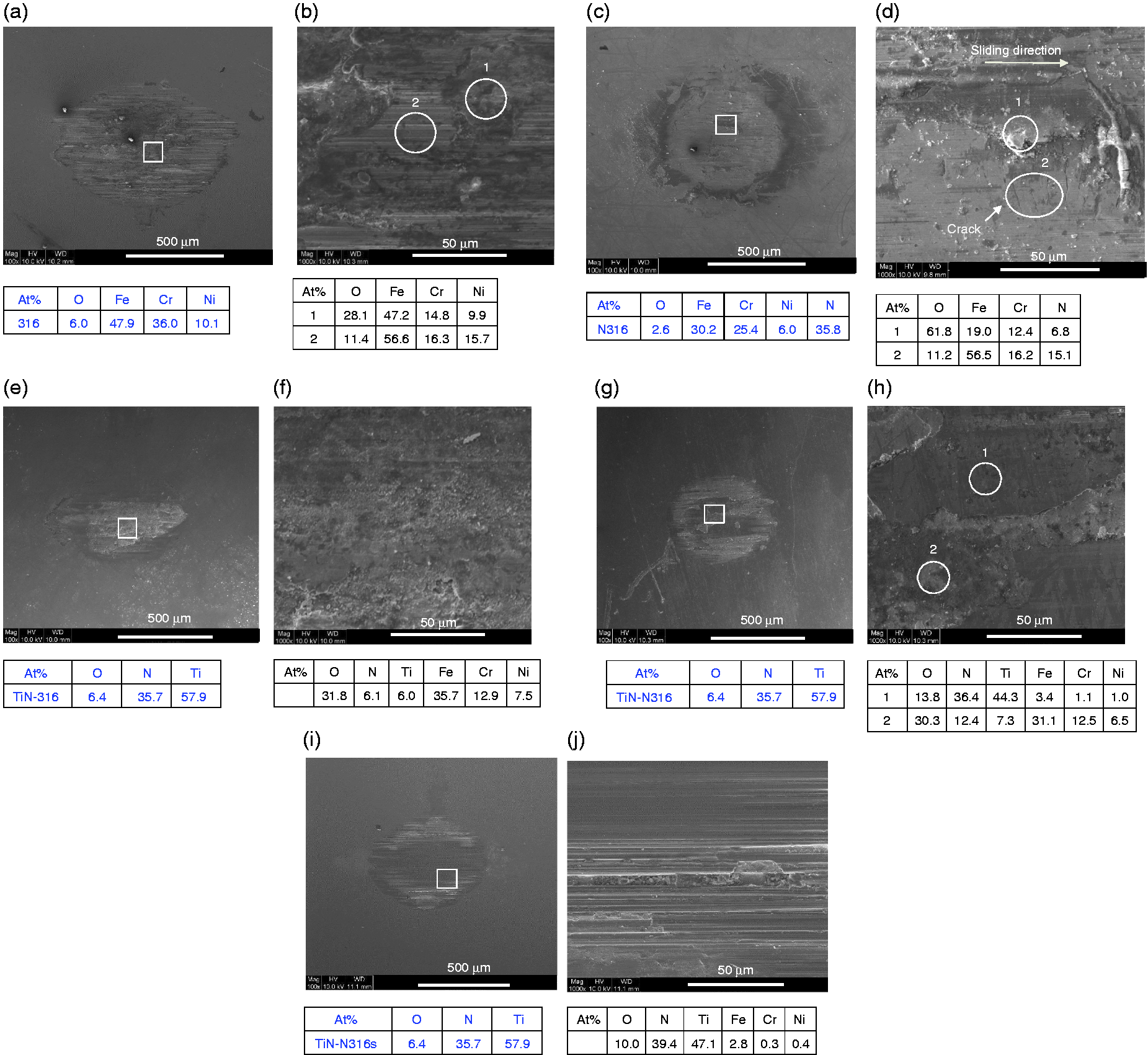
Figure 7(c) shows the wear surface of the N316 sample. The nitriding process increases the surface hardness, and hence the surface damage is less severe than that of the 316 sample. The adhesive region of the surface (WC1) has a high oxygen content of 61.8 at% O, indicating significant oxidation. By contrast, only limited oxidation occurs in the abrasive region (WC2, 11.2 at% O). Thus, for the N316 sample, the main wear mechanism is abrasive wear, which results in the formation of cracks (perpendicular to the sliding direction) and some light scratches on the wear surface (as observed in the magnified SEM image in Figure 7(d)).
Figure 7(e) shows the wear surface of the TiN-316 sample. An obvious fracturing of the TiN coating is observed. The high-magnification SEM image in Figure 7(f) shows that the wear surface is very rough and contains a large number of wear particles. The EDS analysis results show that the wear surface contains 31.8 at% O, 6.1% N, 6.0% Ti and 35.7 at% Fe. Moreover, the wear depth is equal to 2.77 µm (see Figure 5). In other words, the TiN coating is completely worn through and the substrate is exposed. The high oxygen content of the wear surface (31.8 at%) indicates that significant surface oxidation occurs during the sliding process. Thus, the wear mechanism for the TiN-316 sample is dominated by tribo-oxidation and adhesive wear.
Figure 7(g) shows the wear surface of the TiN-N316 sample. The surface wear and damage are significantly reduced compared to that of the original 316 sample (Figure 7(a) and (b)). Hence, it is confirmed that the duplex surface treatment provides an effective improvement in the wear resistance during sliding. As shown in the magnified image in Figure 7(g), the wear surface contains two different types of region, namely a smooth region (WC1) and a rough region (WC2). The smooth region contains 36.4 at% N and 44.3 at% Ti, which indicates the existence of residual TiN coating. By contrast, the rough region contains 30.3 at% O, 31.1 at% Fe and just 7.3 at% Ti. In other words, tribo-oxidation occurs on the surface (as evidenced by the high O content) and the TiN coating is partially fractured and removed (as evidenced by the low Ti content and high Fe content.)
Finally, Figure 7(i) and (j) shows the wear surface of the TiN-N316s sample. The wear surface is smooth, but contains some shallow grooves running parallel to the sliding direction. The EDS results show that the wear surface contains both a high N content (39.4 at%) and a high Ti content (47.1 at% Ti). Furthermore, the wear depth is just 1.19 µm (Figure 5). Thus, while some abrasive wear occurs during sliding (as evidenced by the shallow grooves in Figure 7(j)), the TiN coating remains largely intact.
Overall, the results presented in Figure 7 indicate that the duplex surface treatment improves the adhesive wear resistance of the sample, with the result that the main wear mechanism in sliding against the 316L counterbody is that of abrasion wear. Notably, the duplex-treated TiN coatings have a hardness greater than 16 GPa (Table 4). As a result, the wear resistance of the sample increases, and thus the wear surface contains only shallow scratches and has a low average wear depth.
Figure 8 presents SEM images showing the wear surfaces of the various samples following sliding against the Si3N4 ball. The images in Figure 8(a) and (b) show that the wear surface of the 316 sample is rough and contains deep ploughing grooves in a direction parallel to the sliding direction. The EDS analysis results show that the wear surface contains 33.6 at% O. Hence, it is inferred that the wear mechanism is one of abrasion and tribo-oxidation. For the N316 sample, the wear surface contains 30.5 at% O and 4.4 at% N (see Figure 8(c) and (d)). In other words, significant oxidation occurs during sliding. Moreover, the surface shows obvious scratch marks. The scratches have a depth of 5.6 µm (see Figure 5), and hence penetrate through the nitride layer into the underlying substrate. Overall, the results show that the N316 sample also has a mixed abrasion and tribo-oxidation wear mode. Figure 8(e) and (f) shows the wear surface of the TiN-316 sample. For the WC1 region in Figure 8(f), the wear surface contains scratch marks and has a content of 14.2 at% O, 2.9 at% Si and 53.7 at% Fe. It is thus inferred that the TiN coating fractures under sliding and the wear extends into the substrate. The WC2 region of the wear surface contains prominent protrusions containing 61.2 at% O and 21.0 at% Si. In other words, the sliding process results not only in significant oxidation of the wear surface, but also the transfer of Si from the Si3N4 ball to the wear surface.
Wear surfaces following sliding against Si3N4 ball: (a) 316, (b) 316 (1000×), (c) N316, (d) N316 (1000×), (e) TiN-316, (f) TiN-316 (1000×), (g) TiN-N316, (h) TiN-N316 (1000×), (i) TiN-N316s, and (j) TiN-N316s (1000×).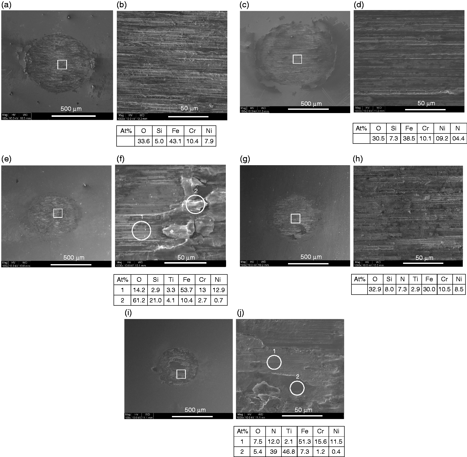
Figure 8(g) and (h) shows the wear surface of the TiN-N316 sample. The surface contains obvious abrasive scratches and signs of tribo-oxidation (32.9 at% O). The average wear depth is equal to 4.25 µm (Figure 5), which exceeds the thickness of the TiN coating (1.7 µm). In other words, the sliding process results in the complete removal of the TiN coating and the wear scar extends into the nitrided layer. Figure 8(i) and (j) shows the wear surface of the TiN-N316s sample. In contrast to the other samples, the wear surface is relatively undamaged and smooth. However, the average wear depth is equal to 2.06 µm (Figure 4), which indicates that the TiN coating is partially broken (see region WC1 in Figure 8(j)). Comparing the SEM images in Figure 8(i) and (j) with those in Figure 8(g) and (h), respectively, it is seen that while the sliding process results in the complete removal of the TiN coating in the wear region of the TiN-N316 sample, some residual coating remains in the case of the TiN-N316s sample. In other words, the results show that for sliding against the Si3N4 counterbody, the TiN-N316s sample, with the highest critical load of the three coated samples (see Table 4), provides the best anti-wear performance.
In summary, the 316 sample has low hardness (i.e. 3 GPa, Table 4). Thus, during sliding against the Si3N4 ball, the sample experiences significant abrasive wear and tribo-oxidation. Following the nitriding process, the surface hardness increases to 5.5 GPa. Consequently, the abrasive wear is reduced, and the wear surface is characterised by shallow scratch marks and decreased tribo-oxidation. The TiN coating further improves the wear resistance of the samples due to an additional increase in the surface hardness. Thus, the wear surfaces of the TiN-316 and TiN-N316 samples exhibit only mild abrasion wear and tribo-oxidation. Furthermore, for the TiN-N316s sample, some residual coating remains on the wear surface following sliding and only shallow scratch marks are observed.
Figure 9 shows the wear surfaces of the various samples following sliding against the Ti6Al4V ball. Figure 9(a) and (b) shows that the surface of the 316 sample contains a large wear region. Moreover, it is apparent that the sample surface undergoes significant shearing and plastic deformation during sliding. The 316 sample and Ti6Al4V counterbody both have low hardness values (i.e. 3.0 GPa and 3.1 GPa, respectively; Table 4). Furthermore, the Ti6Al4V counterbody also has a low elastic modulus (114.2 GPa).
37
Thus, the 316 wear surface not only experiences significant plastic deformation, but also material transfer from the Ti6Al4V counterbody. Consequently, the EDS analysis results presented in Figure 9(b) show that the wear surface contains 24.4 at% O, 13.1 at% Ti and 42.5 at% Fe. Figure 9(c) shows that the wear scar on the surface of the N316 sample is significantly smaller and shallower than that on the 316 surface. However, the magnified image in Figure 9(c) reveals the presence of some scratches and cracks (indicated by the arrows in Figure 9(d)). Hence, it is inferred that the wear mechanism for the N316 sample is one of abrasive wear and crack fracture. Figure 9(e) and (f) shows the wear surface of the TiN-316 sample. As shown in Figure 9(f), the wear surface contains both rough regions containing piles of accumulated debris (region WC1) and smooth regions with scratches (region WC2). The rough region contains 48.5 at% O, 29.0 at% Ti and 14.3 at% Fe, which indicates the occurrence of significant surface oxidation. However, the smooth region contains only 9.5 at% O. In other words, only limited oxidation occurs. However, the wear scars have a depth of 8.35 µm and thus penetrate deeply into the underlying substrate.
Wear surfaces following sliding against Ti6Al4V ball: (a) 316, (b) 316 (1000×), (c) N316, (d) N316 (1000×), (e) TiN-316, (f) TiN-316 (1000×), (g) TiN-N316, (h) TiN-N316 (1000×), (i) TiN-N316s, and (j) TiN-N316s (1000×).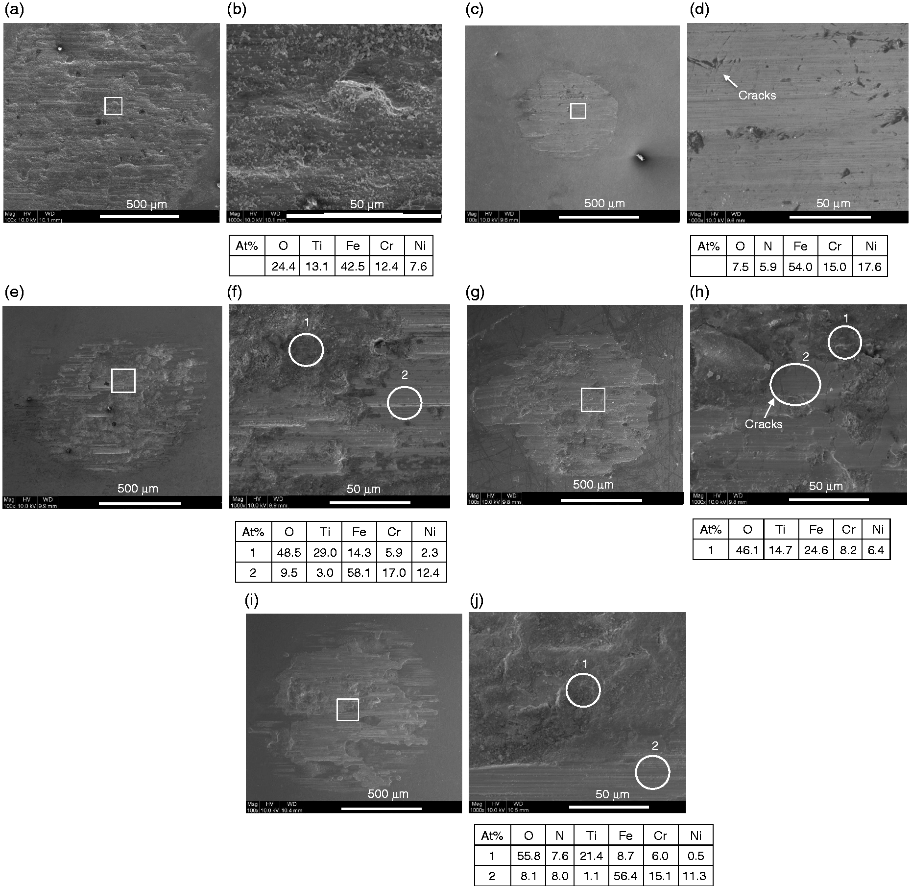
Figure 9(g) and (h) shows the wear surface of the TiN-N316 sample. The wear scratches are less deep than those on the TiN-316 sample. However, the wear depth (6.96 µm) still exceeds the TiN coating thickness, and hence the underlying substrate is exposed during sliding. As shown in Figure 9(h), the rough region of the wear surface (WC1) shows evidence of significant oxidation (46.1 at% O). Furthermore, the smooth region (WC2) contains some cracks running in a direction perpendicular to the direction of sliding. The SEM images presented in Figure 9(i) and (j) shows that the wear surface of the TiN-N316s sample is similar to that of the TiN-N316 sample. However, the wear depth is reduced (5.65 µm). As shown in Figure 9(j), the rough region of the wear surface (WC1) is covered with oxidative debris with a high oxygen content of 55.8 at%. In addition, the smooth area of the wear surface (WC2) contains light scratches and has an oxygen content of 8.1 at% and a high iron content of 56.4 at%. Thus, the wear mechanism is dominated by surface oxidation and abrasive wear.
In general, the TiN coatings are easily broken when sliding against the Ti6Al4V ball due to adhesion effects between the coating and the counterbody. Consequently, the wear resistance is determined principally by the hardness of the substrate. As a result, the nitrided sample provides a better wear resistance than the untreated sample. Despite the tendency of the TiN coatings to rupture, the TiN-N316 and TiN-N316s samples exhibit a lower wear depth than the uncoated samples. Thus, the effectiveness of the duplex surface treatment in improving the wear resistance of the 316L substrate is confirmed. Of the two duplex-treated samples, the TiN-N316s sample has the best wear resistance due to its higher critical load (56 N) and hardness (21.9 GPa).
Electrochemical properties
Figure 10 shows the polarisation curves of the various treated and untreated samples. Each curve comprises three distinct regions, namely an active region, a passive region and a trans-passive region. Based on these curves, Table 5 shows the corrosion potential (Ecorr) and breakdown potential (Epitting) for each sample. The TiN-N316s sample has the highest values of both Ecorr (-0.136V) and Epitting (1.632V). In other words, the duplex surface treatment (with a polishing operation prior to TiN deposition) results in an excellent corrosion resistance. TiN coatings typically have a columnar structure (as shown in Figure 2(a)), in which pinholes are inevitably present. Corrosive media can reach the substrate through these pinholes and cause localised corrosion.38,39 Thus, the electrochemical behaviour of TiN-coated samples depends fundamentally on the substrate properties. Consequently, the polarisation curve for the TiN-316 sample is similar to that of the 316 sample. However, nitrided layers have a dense structure, which inhibits the penetration of corrosive media. Thus, in contrast to the TiN-316 sample, the N316 sample has a higher breakdown potential. The duplex treatment process (i.e., nitriding followed by TiN coating deposition) increases both the corrosion potential and the breakdown potential. It was reported
40
that a lower surface roughness increases the corrosion potential and breakdown potential. Moreover, a high breakdown potential results in decreased pitting. Consequently, of all the samples, the TiN-N316s sample exhibits the best anti-corrosion properties.
Polarisation curves for various specimens. (Note that the inset shows magnified views of the turning point region in each polarisation curve.) Corrosion potential and breakdown potential of coated and uncoated samples.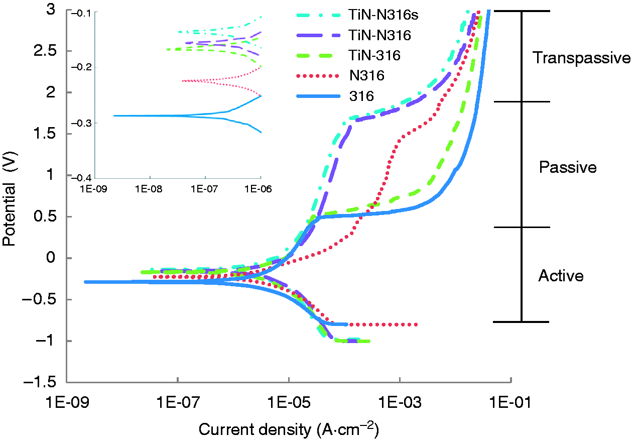
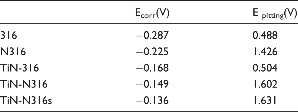
Figure 11 presents SEM images of the sample surfaces following the potentiodynamic tests. As shown in Figure 11(a) and (b), the surface of the 316 sample shows extensive deep pitting (black points). The N316 sample also shows surface pitting (see Figure 11(c)). However, compared to the 316 sample, the degree of pitting is reduced. The high-magnification image presented in Figure 11(c) shows that the nitride layer is damaged and broken around the deep pits. As shown in Figure 10, the TiN-316, TiN-N316 and TiN-N316s samples all display a prominent trans-passive region, and hence the corrosive surfaces all show clear signs of TiN coating delamination. For the TiN-316 sample, the TiN coating is pitted and broken (see Figure 11(e)). Furthermore, in some regions of the surface, the TiN coating is delaminated and some of the coating layers are missing (see Figure 11(f)). The TiN-N316 and TiN-N316s samples also exhibit a partial delamination of the TiN coating (see Figure 11(g) and (i)). However, the pitting is less severe than for the TiN-316 sample (see Figure 11(h) and (j)). Comparing the three coated samples, it is seen that the TiN-N316s sample has the smallest pitting holes. In other words, the superior corrosion performance of the TiN-N316s sample is confirmed.
SEM images of samples following corrosion test: (a) 316, (b) 316 (1000×), (c) N316, (d) N316 (1000×), (e) TiN-316, (f) TiN-316 (1000×), (g) TiN-N316, (h) TiN-N316 (1000×), (i) TiN-N316s and (j) TiN-N316s (1000×).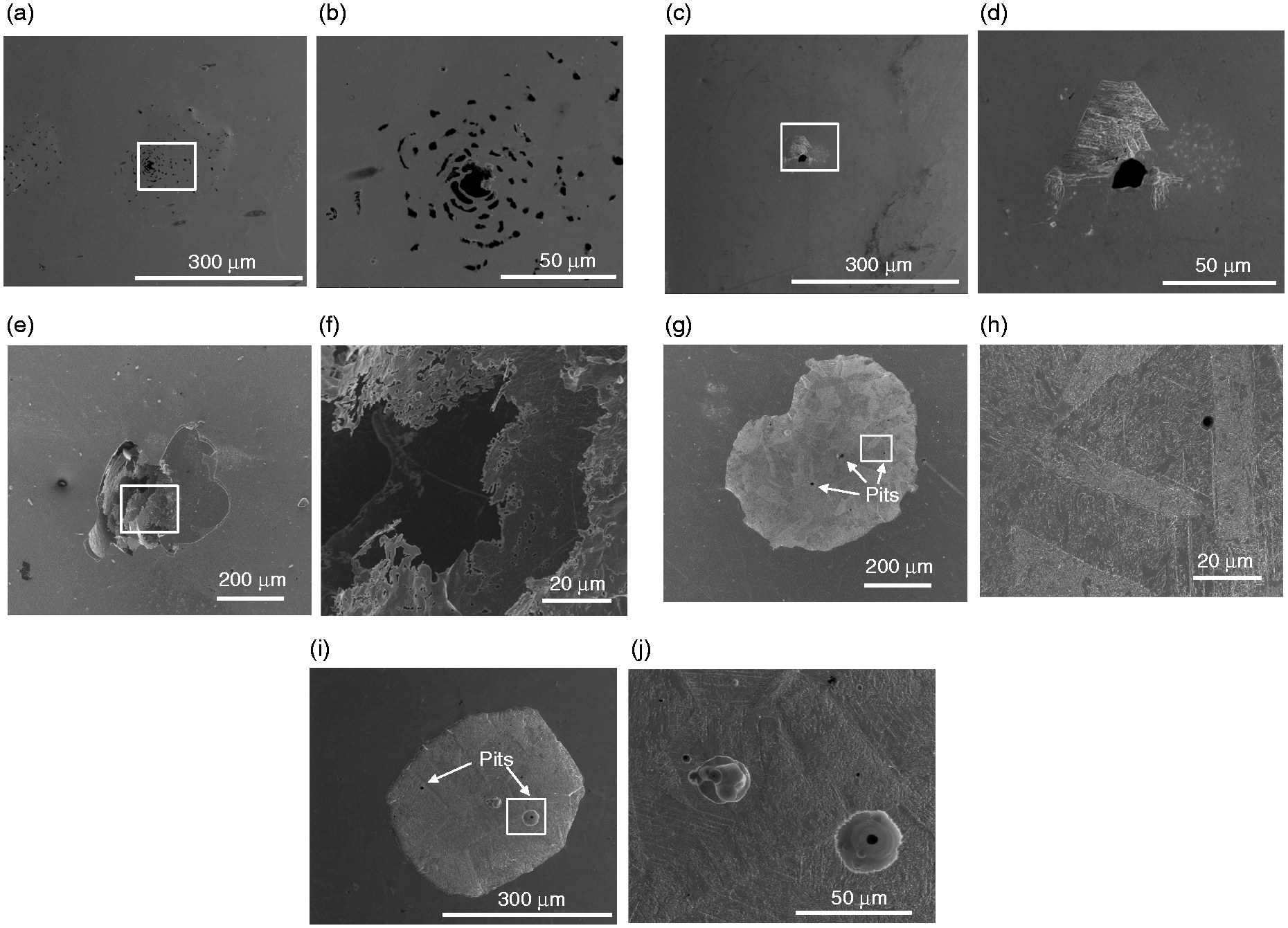
Biocompatibility
Figure 12 shows the cell density on the surfaces of the various samples following culturing periods of one, three and five days, respectively. After one day, the cell density ranges from 7449 to 13194 (cells/cm2). After three days, the number of cells on the nitrided and TiN-coated samples is notably higher than that on the untreated 316 substrate. For example, the 316 sample has a cell density of 16,461 (cells/cm2), while that of the nitrided and TiN-coated samples exceeds 27,727 (cells/cm2). Moreover, the cell density on the duplex-treated samples is higher than that on the nitrided sample. After five days, the untreated 316 sample has a cell density of 45,753 (cells/cm2), while the nitrided N316 sample has a cell density of 60,398 (cells/cm2). Furthermore, the TiN-coated samples have an even higher cell density in the range of 75,044 cells/cm2 (TiN-N316) to 80,902 cells/cm2 (TiN-316).
Number of cells on sample surface following culturing periods of one, three and five days.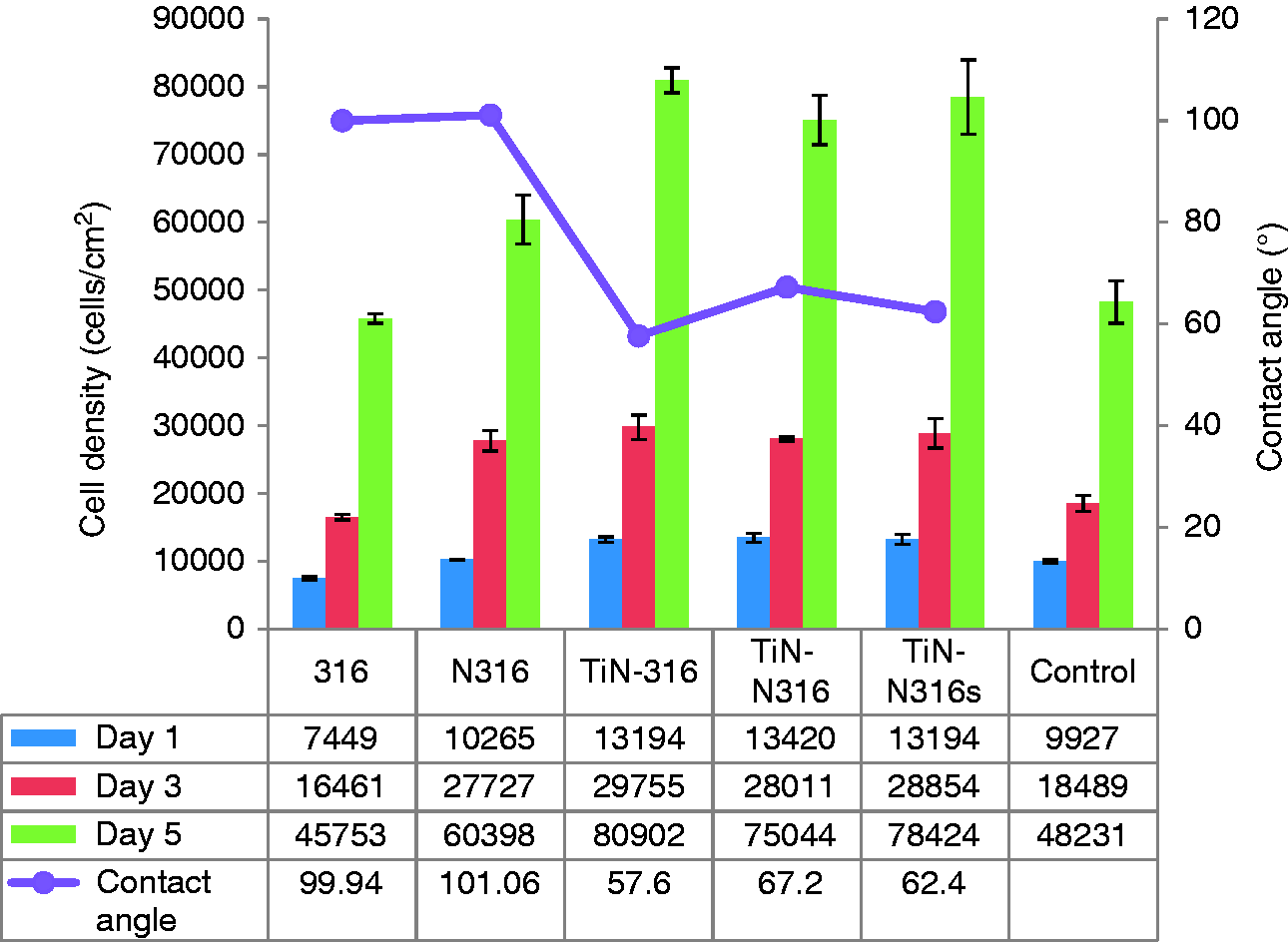
In general, the interaction between biological cells and a surface depends on many factors, including the topography and roughness of the surface, and its chemical and physicochemical properties (e.g. the surface wettability and surface modification). 41 Plasma nitriding is a non-cytotoxic surface treatment, and hence the cell viability is increased. Consequently, the N316 sample has a greater cell density than the untreated 316 sample. As shown in Figure 12, all of the TiN-coated samples have excellent biocompatibility. It was suggested 42 that the superior biocompatibility of TiN-coated samples can be attributed to the relatively higher concentration of nitrogen on the adsorption surface. The difference in the cell densities of the three TiN-coated samples can be attributed to differences in the contact angle. Hydrophilic surfaces absorb more protein and are more favourable to cell attachment than hydrophobic surfaces. 43 Consequently, the TiN-316 sample, with the lowest contact angle (57.6°) of the three TiN-coated samples, has a slightly better biocompatibility than the TiN-N316 sample (67.2°) or TiN-N316s sample (62.4°). The smaller contact angle of the TiN-316 sample can be attributed to its lower surface roughness (see Table 4).
Figure 13 presents SEM images of the Raw 264.7 cells on the surface of the TiN-316 sample following culturing periods of one, three and five days, respectively. After one day, the surface contains a relatively small number of cells (Figure 13(a)). However, after three days, the number of cells is greatly increased (Figure 13(b)). Notably, the surfaces of the cells are not damaged and there is no sign of atrophy. After five days, the number of cells increases to such an extent that the surface is almost completely covered (Figure 13(c)), The magnified image presented in Figure 13(d) shows that the cells have a rounded or polygonal morphology, which indicates that the cells are well-adhered to the surface.
SEM images of Raw 264.7 cells on surface of TiN-316 sample following different culturing periods: (a) one day, (b) three days, (c) five days, and (d) five days (1000×).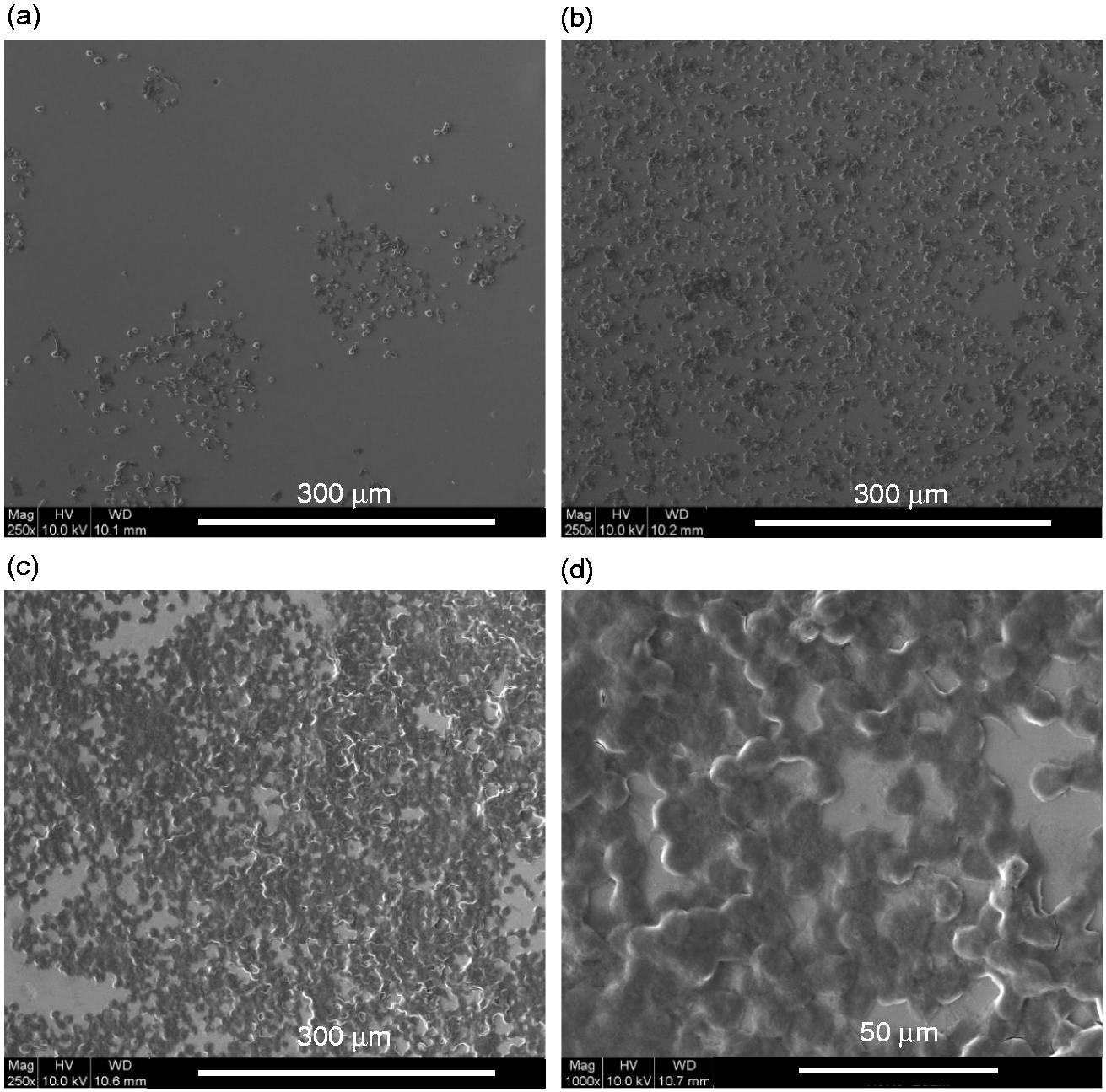
Overall, the results presented in Figures 12 and 13 show that the TiN-coated samples in general (and the TiN-316 sample in particular) have excellent biocompatibility in addition to good tribological and anti-corrosion properties
Conclusions
This study has investigated the tribological, electrochemical and biocompatibility properties of AISI 316L substrates processed using a duplex surface treatment consisting of plasma nitriding followed by TiN coating deposition. The results have shown that in reciprocating wear tests performed against 316L, Si3N4 and Ti6Al4V balls, respectively, the lowest wear rate occurs when sliding against the 316L ball, while the maximum wear rate occurs when sliding against the Ti6Al4V ball. Of all the wear pairs, the TiN-N316s sample sliding against the 316L ball exhibits the best tribological properties, including the lowest wear depth, wear rate and friction coefficient. The TiN-N316s sample also shows the highest corrosion potential and breakdown potential of the various samples in 0.9 wt.% NaCl solution. In other words, the duplex surface treatment (with a polishing process performed prior to TiN coating deposition) yields an effective improvement in the corrosion resistance of the original 316 L substrate. Finally, it has been shown that the samples with TiN coatings exhibit a better cell viability than the original 316L substrate or the nitrided 316L substrate. Thus, the TiN-coating enhances the biocompatibility of the original and nitrided substrates. Of the various TiN-coated samples, the TiN-316 sample has the best biocompatibility performance due to its superior wettability (i.e. greater hydrophilicity).
Overall, the results presented in this study show that plasma nitriding followed by TiN coating deposition yields an effective improvement in the wear resistance, corrosion resistance and biocompatibility of AISI 316L stainless steel. Consequently, the duplex surface treatment provides a promising route for extending the use of AISI 316L in biomedical implant applications.
Footnotes
Acknowledgements
The authors would like to thank the Instrument Center of National Cheng Kung University for providing the analytic apparatus used in the present study.
Declaration of Conflicting Interests
The author(s) declared no potential conflicts of interest with respect to the research, authorship, and/or publication of this article.
Funding
The author(s) disclosed receipt of the following financial support for the research, authorship, and/or publication of this article: Ministry of Science and Technology of Taiwan under Contract No. MOST 104-2221-E270-006.