






Abstract
Locking compression plate (LCP) has conventionally been the most extensively employed plate in internal fixation bone implants used in orthopaedic applications. LCP is usually made up of non-biodegradable materials that have a higher mechanical capability. Biodegradable materials, by and large, have less mechanical strength at the point of implantation and lose strength even more after a few months of continuous degradation in the physiological environment. To attain the adequate mechanical capability of a biodegradable bone implant plate, LCP has been modified by adding laddered – type semicircular filleted embossed structure. This improved design may be named as laddered embossed locking compression plate (LELCP). It is likely to provide additional mechanical strength with the most eligible biodegradable material, namely, Mg-alloy, even after continuous degradation that results in diminished thickness. For mechanical validation and comparison of LELCP made up of Mg-alloy, four-point bending test (4PBT) and axial compressive test (ACT) have been performed on LELCP, LCP and continuously degraded LELCP (CD-LELCP) with the aid of finite element method (FEM) for the assembly of bone segments, plate and screw segments. LELCP, when subjected to the above mentioned two tests, has been observed to provide 26% and 10.4% lower equivalent stress, respectively, than LCP without degradation. It is also observed mechanically safe and capable of up to 2 and 6 months of continuous degradation (uniform reduction in thickness) for 4PBT and ACT, respectively. These results have also been found reasonably accurate through real-time surgical simulations by approaching the most optimal mesh. According to these improved mechanical performance parameters, LELCP may be used or considered as a viable biodegradable implant plate option in the future after real life or in vivo validation.
Introduction
In the evolution of orthopaedic implants, biodegradable materials have been the well-known and traditional area of research for bone implants because biodegradable materials like Mg-alloy and Zn-alloy have an ability to avoid most of the complications arrived via bone implants made up of non-biodegradable materials.1,2 Some of these critical complications are re-surgery for removal/replacement of bone implant post healing, a long-term infection that commonly arises with non-biodegradable biomaterials, etc. 3 To avoid these critical issues, a biodegradable implant made up of biodegradable materials can turn out to be a big boon for orthopaedic patients.4,5 Mechanical strength (in terms of density, yield strength, etc.) of the biodegradable materials (Mg-alloy, Zn-alloy, etc.) is 50%–75% less than that of non-biodegradable materials.2,6–11 Most conventionally used plates (LCP, etc.) have been made with non-biodegradable materials (Ti-alloy, SS-alloy, etc.) which might not compare well with biodegradable materials in terms of mechanical ability. Therefore, the biodegradable bone implant plate needs to be upgraded for superior mechanical capability because biodegradable materials can never reach as high mechanical strength as non-biodegradable materials. Not a significant bit of research appears to be available yet, with its focus on improving the design of the biodegradable implant plate.12–14
The most commonly used plate for bone fracture fixation is LCP which is having two important features; first, the union of two circular holes (UTCHs) for aligning and fixing of screws (one for fixing perpendicularly through the longitudinal axis of the plate, and another one to provide dynamic compression corresponding to different angular alignments); and second, symmetric multiple grooves in the lower section of LCP for limiting the contacts between the plate and bone.15,16 LCP is found to be the most efficient plate for bone fracture fixation with a non-biodegradable type material like Ti-alloy due to the encouraging experimental results. To balance the overall mechanical performance of biodegradable bone implant plate, the design of LCP needs improvement because LCP made up of Mg-alloys is already less efficient per se and its efficiency decreases further with continuous degradation and accompanying decrease in plate thickness. The aim is to achieve sufficient strength even after/during continuous corrosion, to make the LCP suitable to be employed in a biodegradable bone implant made of a suitable biodegradable material such as Mg-alloy.
For improving the mechanical ability of biodegradable implant plates, LCP has been upgraded. The upper section of LCP is a fully plain or flat surface that can be utilized to improve the mechanical performance of the LCP because solely increasing the thickness of the plate may not be desirable due to patient discomfort, as also higher degradation time. Generally, the cross-section of the LCP plate is crescent type (intersection of two circles where the centreline is the thickest portion)15,17 to avoid bending and fit properly with a fractured, circular bone. When the bending and compression movements have occurred with multidirectional force, stress is generated on the thinnest portion of the plate. This stress concentration can be avoided by adding emboss to it.
In orthopaedics, most of the invasive medical devices cannot be adequately tested mechanically under physiological environment (PE), when it is not degraded continuously with time. For all these validation difficulties, FEM can be used for understanding the approximate mechanical behaviour via similar boundary conditions. 18 For a continuously degrading implant, it would be even more difficult to achieve the exact mechanical behaviour of the implant for its appropriate validation. Therefore, FEM appears to be the best alternative to validate medical devices for similar boundary conditions and assumptions which can provide approximate validation of results with the help of real-time surgical simulation.19,20 FEM is used for all such validation in biodegradable implant plates.21,22
This study is a comparative structural design analysis, where both LCP and LELCP are made of qualified biodegradable material, that is, Mg-alloy, where there is a new approach to get mechanically more suitable biodegradable bone implant plates by improving the structural design of LCP with the help of adding a terraced semi-circular filleted embossed structure. There have been mainly two mechanical tests using FEM to measure mechanical performance even after continuous degradation of LELCP as stress, its concentration and deformation.
Designing of laddered embossed locking compression plate (LELCP)
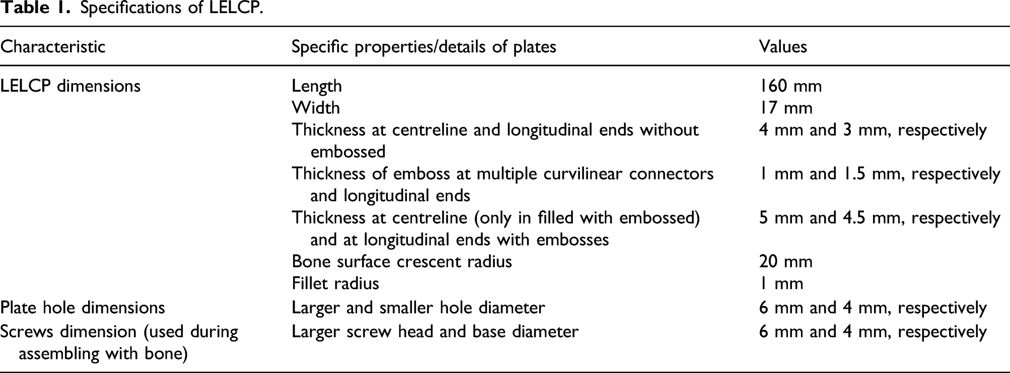
For arriving at an appropriate design of a biodegradable implant plate, LCP design has to be improved with its focus on enhancing the mechanical capability because LCP has already achieved great success with non-biodegradable materials.1,23 In the LCP, the cross-section is similar to a crescent shape (interconnection of two circles) where the tangential end is thinner and the centreline is thicker.15,17 This thinner section and its multiple tangential interconnections may be useful in improving the mechanical capability of LCP without affecting the comfort level of orthopaedic patients. These regions of LCP exhibit higher stress concentration during torsion and bending, due to lower thickness. To minimize this effect and improve mechanical performance, a semi-circular embossed structure is provided longitudinally at the ends’ (about 1.5 mm radius semi-circular filleted) embosses and multiple curvilinear connectors between tangential interconnections’ (about 1.0 mm radius semi-circular filleted) embosses, to connect both the symmetric emboss up to the termination of ends. This LCP is shown in Figure 1, where it is looking like a laddered embossed structure on the upper surface of the LCP, therefore named as laddered embossed locking compression plate (LELCP). Specifications of LELCP are listed in Table 1. Different views of LELCP in (a) tilt view, (b) top view, (c) bottom view, (d) front view, and (e) side view. Specifications of LELCP.
For a successful biodegradable implant plate, the mechanical strength of LCP has to be improved. LELCP must be capable enough of providing adequate mechanical strength while going through continuous degradation. Ideally, a biodegradable plate, under PE, should degrade uniformly from all sides with a constant rate of biodegradation. However, it neither degrades uniformly throughout the healing process nor degrades uniformly for different age groups/multiple fixation sites, etc. due to different blood flow rates.2,24 This is because the blood flow at the interface of the implant generates oxygen, which promotes corrosion/biodegradation.2,25 Therefore, the biodegradation rate of the plate is assumed to be constant and uniform throughout the surface of the plate and across the cycle of healing. This degradation rate is assumed as 4 mm/year26–30 and is essentially based on recently developed Mg-alloys’ biodegradation rates. This is needed to evaluate the mechanical effects during the process of continuous degradation where the reduction in thickness of the plate is taken symmetrically and uniformly from both the surfaces, with the total deduction in 1 month is about 0.33 mm. It is also assumed that thickness of the plate is the most critical dimension as opposed to its length and width
22
because minor changes in thickness can drastically increase and decrease the stresses or deformation. Therefore, changes in length and width are ignored during the continuous biodegradation of the plate. Its degraded form is observed at a time step of two months. In other words, ∼0.66 mm has been used for observation while reducing thickness uniformly at each step from top to bottom for every two months after the degradation of the plate. The observations have been shown in Figure 2. Expected continuously degraded forms (reduced thickness) of LELCP in the top and left views from the top to bottom at time step of 2 months (0.66 mm reduced thickness for each step).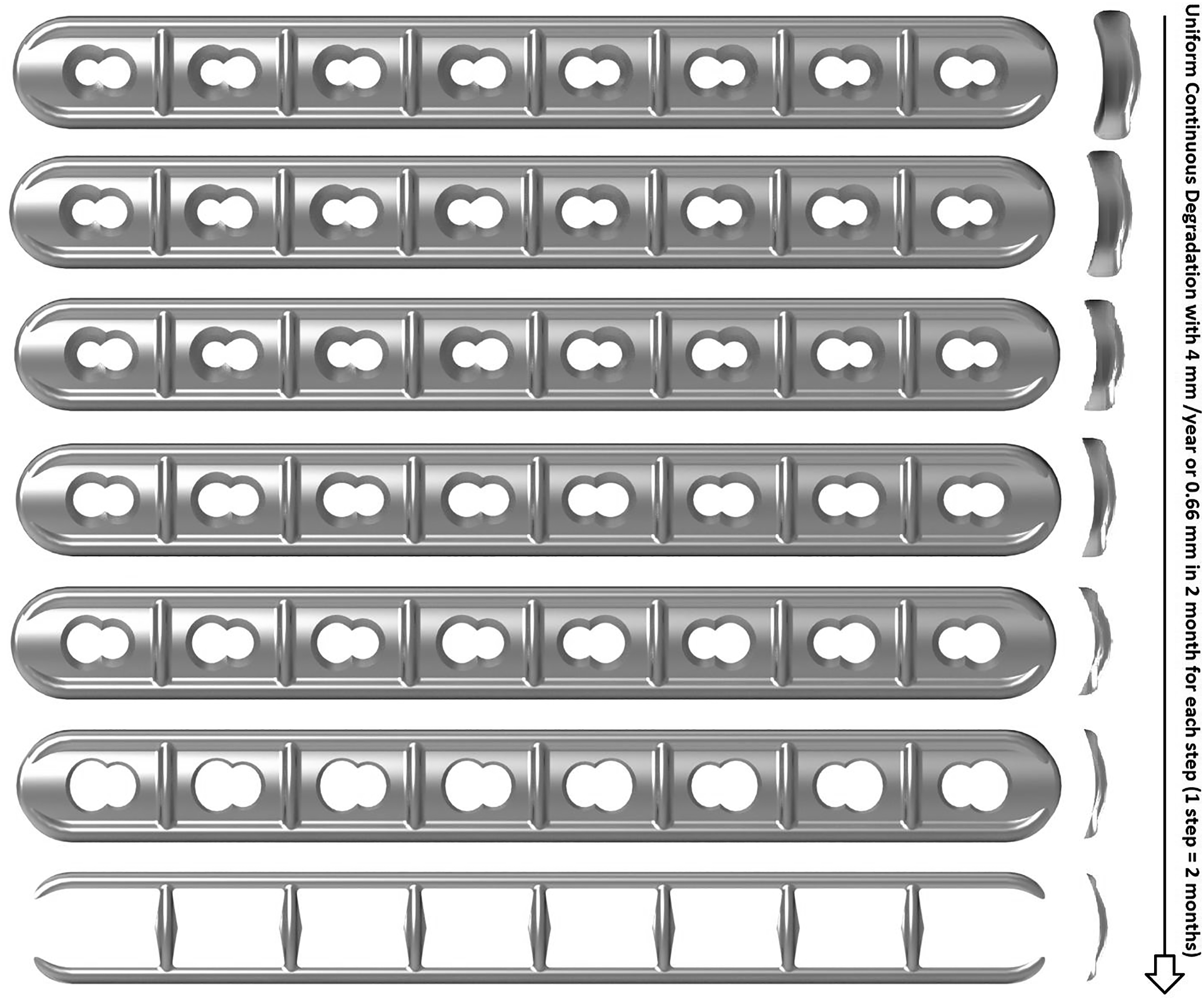
Materials and methodology
Material selection and assumptions

Assumptions and boundary configurations
For testing LELCP, two types of tests, namely, bending and compression, are needed to be performed to check the mechanical capability for LELCP, LCP and continuously degraded (reduced thickness uniformly for the entire surface) LELCP (CD-LELCP). For the bending test, a four-point bending test has been performed according to the ASTM F382-17 standard using FEM.
17
For this test configuration, 4 semicylindrical blocks have been prepared to fit in such a way that 2 blocks are fitted below the plate with a fixed support at a distance of 48 mm each from the centre and 2 blocks are fitted above the plate (as a pusher) at a distance of 19 mm each from the centre. The pusher and support are both considered rigid bodies in the 4PBT. 4PBT configuration is shown in Figure 3(a) and (b) for LELEP and LCP plate, respectively. Testing configurations for (a) 4PBT of LELCP (front view), (b) 4PBT of LCP (front view), (c) ACT of LELCP (top view) and (d) ACT of LCP (top view). ACT: axial compressive test.
For ACT, assembly of the plate, 8 segments of screws and 2 fracture segments of bone have been taken and fitted in such a way that the plate is tightened with 8 segments of locking screws fitted on bone holes. Locking screws are bonded to holes provided in the plate. The conventional gap between bone fracture segments varies from 1 mm to 5 mm. Accordingly, this gap has been assumed to be 2 mm for superior healing and compatibility considerations. The gap between bone and plate usually varies from 0 mm to 4 mm and has been assumed to be 1 mm here, for adequate support to the soft callus formed during the initial phase of healing. The bone diameter has been taken as 28 mm (similar to a femur bone) for the analysis of LELCP. As for the mechanical properties of the bone used for this study, the bone is assumed to be like cortical bone, as also listed in Table 2. This configuration is shown in Figure 3(c) and (d) for LELCP and LCP, respectively.
All mechanical properties are taken to be uniform throughout the surfaces, and along the axes of the LELCP, LCP and CD-LELCP. Locking Screws used are made up of Mg-alloy but it is assumed that no time-dependent biodegradation has been considered/assumed in any screw.
Four-point bending test (4PBT) on LELCP, LCP and CD-LELCP
More often than not, the plate fails due to a significant bit of bending in the plate or high shear stress due to multidirectional bending loads.
37
An implant plate must have adequate overall mechanical ability to sustain such stresses during normal (or occasionally abnormal) routine human activities. To observe bending behaviour in the implant plate, a single cycle four-point bending test (4PBT) is performed statically to measure the mechanical capability in terms of vertical incremental deformation and equivalent stress generated or stress concentrated regions,
38
according to ASTM F382-17
17
using FEM. Some existing research suggests the ways to perform 4PBT25,32,38 and, accordingly, the 4PBT has been performed for all three types of plates, namely, LELCP, LCP and CD-LELCP (uniformly reduced thickness in LELCP). The testing configuration involves 29 mm of loading span distance (b) and 38 mm of the pusher to centre distance (a) being taken with frictionless contacts between semicylindrical block and plate. Related test configurations are listed in Table 3 for proper understanding. According to 4PBT configuration, the maximum slope of the linear elastic zone, K, and normalized effective bending structural stiffness, EI, can be calculated on both plates with the help of the following equations: K = Max. EI = 4PBT configuration and boundary details for LELCP, LCP and CD-LELCP.

Meshing details of continuous degrading LELCP forms after every 2nd month.

Axial compressive test (ACT) on LELCP, LCP and CD-LELCP
ACT configuration and boundary details for LELCP, LCP and CD-LELCP.

Similarly, the axial compressive load of 600 N at the same configuration as shown in Figure 3(c) and listed in Table 5, has also been taken on CD-LELCP at every second elapsed month up to 8 months (0.66 mm reduced thickness uniformly for each step) for analysing the mechanical performance in terms of equivalent stress generated and maximum axial downward deformation when it was assumed that plate is degrading at a rate of 4 mm/year or 0.66 mm degradation in 2 months. For each reduced thickness value of LELCP during continuous degradation, the meshing details are listed in Table 4 based on 2 months step size up to 8 months, during continuous and uniformly diminished thickness.
Mesh convergence and simulation
Real-time surgical simulations usually employ two approaches. The first one aims to compare the results directly between real-time surgery and FEM results with the same boundary conditions. The second one, on the other hand, tries to identify the most economical mesh for realistic approaches using FEM 48 to ensure that the results obtained almost conform with applied boundaries. When the generated results are found almost stable after increasing the number of elements, then any number of elements for this constant value can be chosen for analysis. For a lower number of elements of higher size, discretization and consequent results may vary. Discretization error calculation is a validation technique that calculates the approximate error between values of observation (via FEM) and real-time surgical observations for any computational model/design. It works on applied realistic boundary conditions for any specific application. To determine the most economical mesh, an approximation method is applied for convergence plot at every mesh step for a more realistic approach. For all the above tests, different numbers of elements (from the largest size to the smallest possible size) in increasing order with respect to the generated equivalent stress have been used for constant average applied loads/moments (same as CD-LELCP) at a similar configuration of each test on LELCP and to check for the most economical mesh. This simulation can help in approaching the mechanical behaviour of design compared to real-usage applications by identification of the most economical mesh.
All structural designs and their finite element analysis for this study have been performed using Creo 5.0 (by PTC) and ANSYS 19.0, respectively.
Results and discussion
4PBT results on LELCP, LCP and CD-LELCP
In the structural analysis of LELCP and LCP made up of Mg-alloy, the concentration of vertical deformation and equivalent stress during 4PBT are shown in Figure 4. Different colours are used to indicate maximum and minimum values. In this figure, the concentration of maximum vertical deformation is shown in the middle of plate. It is slightly lower in the LELCP as compared to LCP due to the thicker longitudinal ends of the LELCP. The crescent cross-section of LCP results in diminishing of vertical deformation by avoiding shear stresses in these regions and the effect becomes more pronounced because of the embossed structure. Similarly, in deformed LELCP and LCP, stress concentration appears near the UTCH which is slightly higher in LCP due to thinner longitudinal ends. In LELCP, stress regions are on the lower side as compared to LCP. Embosses on the longitudinal ends and multiple curvilinear connections of LELCP are decreasing the stress concentration intensity in this region. The addition of laddered embossed structure to the LELCP lowers stress concentration and vertical deformation. It may turn out to be helpful when used with continuous biodegradation and reduced LELCP thickness for bearing load boundaries. Deformed views for maximum deformation patterns on the meshed (a) LELCP view, (b) LCP view, (c) LELCP with the enlarged upper view, (d) LELCP with the enlarged bottom view, and for generated stress patterns on the meshed, (e) LELCP view, and (f) LCP view, during 4PBT at an applied load of 100 N.
In the structural analysis of LELCP and LCP made up of Mg-alloy, 4PBT has been performed with different bending loads from 100 N to 1000 N acting vertically downward. The equivalent generated stress in MPa and maximum vertical deformation values in mm have been observed and plotted in Figure 5. It can be seen that in the elastic region, LCP exhibits about 26% and 33% higher equivalent stress and maximum vertical deformation, respectively, than LELCP at each step of incremental bending load. The addition of laddered embossed structure upon the LCP appears to be beneficial for improving the mechanical performance when tested through 4PBT. Comparative plots of equivalent stress and maximum vertical deformation during 4PBT of LELCP and LCP.
According to the maximum applied load and the maximum vertical deformation, the maximum slope of the linear elastic zone, K, is calculated as 0.796 × 10⁶ N/m and 0.598 × 10⁶ N/m for LELCP and LCP, respectively. Similarly, the magnitude of normalized effective bending structural stiffness (EI) is 9.594 N-m2 and 7.2 N-m2 for LELCP and LCP, respectively. These values are calculated for the test configurations and output results using the equations mentioned in four-point bending test (4PBT) on LELCP, LCP and CD-LELCP.
In the structural analysis of CD-LELCP made up of Mg-alloy up to 8 months of continuous degradation, the concentrations of vertical deformation and equivalent stress are shown in Figure 6 that uses different colours for maximum value and minimum value. The concentration or intensity of vertical deformation is found to be increasing continuously from upper to lower LELCP with continuous degradation and uniform reduction in thickness. However, due to embossing at the longitudinal ends, this vertical deformation reduces slightly. Similarly, the concentration of stress in the CD-LELCP also increases longitudinally outwards from upper LELCP to lower LELCP. The distribution of stress concentration across the entire plate area could be attributed to the presence of embosses. The thicker longitudinal ends will help the LELCP stay in PE during continuous degradation for a long term with a minimum possible thickness of LELCP that eventually disappears. Deformed plate views of meshed CD-LELCP as maximum deformation from (a) to (d), and as generated stress from (e) to (h), in every step of two subsequent months of degradation during 4PBT at an applied load of 100 N.
In the structural analysis of CD-LELCP made up of Mg-alloy, 4PBT has been performed with a vertically downward bending load of 100 N (adequate for routine human activity) and the equivalent generated stress (MPa) and maximum vertical deformation (mm) have been observed and plotted in Figure 7. Stress generated after 2 months in the LELCP subjected to continuous degradation (0.66 mm of reduced thickness) is found to be 73.3% and 85.1% less than the corresponding magnitudes after 6 and 8 months respectively. Stress in LELCP after 2 months of continuous degradation exhibits a 7% increase vis-à-vis LCP without degradation. Also, stress generated doesn’t cross the yield strength of Mg-alloy under consideration up to 2.5 months and therefore this period of continuous degradation can be considered to be safe. Also, vertical deformation for continuously degrading LELCP exhibits linear increase and is found to be 185% and 343% more after an elapsed period of 4 and 6 months when compared with LELCP without any degradation. Comparative plot of equivalent stress and maximum vertical deformations for CD-LELCP at every next 2 months during 4PBT.
The results of 4PBT suggest that LELCP made up of Mg-alloy can be a reasonable alternative to LCP and this is attributable to the addition of laddered-type embossed structure at the longitudinal ends and multiple curvilinear connections. During bending, limited contact grooves in the inner curvilinear part are observed to have higher stress concentration and vertical deformation in LCP and LELCP both, but these effects are overcome in LELCP by embosses on multiple curvilinear connections provided just above the limited contact grooves.
ACT results on LELCP, LCP and CD-LELCP
In the structural analyses of LELCP and LCP made up of Mg-alloy, concentrations of vertical deformation and equivalent stress are shown in Figure 8 during ACT, with different colours accounting for maximum and minimum values. The figure shows the concentration of maximum axial deformation to touch its peak towards the middle of the plate (between two UTCHs). This deformation is shown a lesser concentration in LELCP than LCP. The maximum likelihood of deformation is near the gap of the fractured bone which needs to be kept within limits for effective healing taking into account the axial load and flexibility of plate and screws. Sometimes dynamically applied axial loads of magnitude 100–300 N (less than human body weight) are provided dynamic axial interfragmentary movement to enhance the healing performance,
43
but for higher axial static loads, an LCP made up of Mg-alloy may fail due to higher interfragmentary axial deformation. Similarly, stresses exhibit lesser concentration near the UTCHs at the middle of the LELCP than LCP where the maximum stress concentration is shown on the internal surface of deformed UTCH of LCP. These higher axial deformations may also damage the bone (close to the holes) and be detrimental to the healing processes. Deformed plate views at an applied load of 600 N during ACT, for maximum deformation of meshed top views of (a) LELCP and (b) LCP; and the generated stress of meshed (c) top view and (d) bottom view of LELCP, and (e) top view of LCP and (f) bottom view of LCP.
The structural analysis of LELCP and LCP made up of Mg-alloy involves axial compression with multiple axial compressive loads ranging from 200 N to 1200 N. The equivalent generated stress (MPa) and factor of safety (FOS) have been observed and plotted in Figure 9(a). The equivalent stress is observed to be 10.4% higher in LCP than LELCP at every subsequent loading step. The factor of safety appears to be slightly higher in LELCP than LCP at each loading step. Comparative plots of (a) equivalent stress and factor of safety (b) maximum axial deformation with the applied axial compressive load during ACT of LELCP and LCP.
Similarly, maximum axial deformation (mm) has also been observed through the same test and plotted in Figure 9(b). The axial deformation corresponding to every axial compressive loading step is about 6% higher in LCP as compared to LELCP. The difference in axial deformation (about 2 μm) can still be ignored as the actual magnitude of interfragmentary axial deformation is not sufficient to harm the healing process.
The concentration of axial deformation and equivalent stress for CD-LELCP made up of Mg-alloy is shown in Figure 10 during ACT with 600 N constant load and up to 8 months of continuous degradation; different colours indicating the maximum value and the minimum value. The concentration of axial deformation in CD-LELCP, after 6 or 8 months, is significantly higher than the corresponding values after 2 or 4 months because the middle section of the LELCP starts buckling after 6 or 8 months. The addition of ladder-type embossed structure also helps in minimizing the axial deformation and avoiding any possible damage to the healing process up to 6 months. Similarly, the stress in the LELCP is observed higher near the UTCHs throughout the longitudinal ends and shows a continuous increase at each step of continuous degradation. Deformed plate views of meshed CD-LELCP in terms of maximum deformation and generated stress in every next 2 months of degradation from (a) to (h), during ACT at the applied load of 600 N.
In the structural analysis of CD-LELCP made up of Mg-alloy, ACT has been performed with an axial compressive load of 600 N (close to average human body weight). The equivalent generated stress (in MPa) and maximum axial deformation (in mm) have been observed and plotted in Figure 11. The maximum generated stress in the LELCP after 6 months is observed to be unsafe, but up to 6 months, the lower equivalent stress indicates safe operation. In the degraded LELCP, comparatively low differences of equivalent stresses have been observed for up to 6 months. The ladder-type embossed structure is capable of avoiding extra axial deformation due to the presence of embosses at longitudinal ends. The low axial deformation and low equivalent stress make LELCP a reasonable and viable alternative to a biodegradable implant plate. Comparative plot of equivalent stress and maximum vertical deformations for CD-LELCP at every next 2 months during ACT.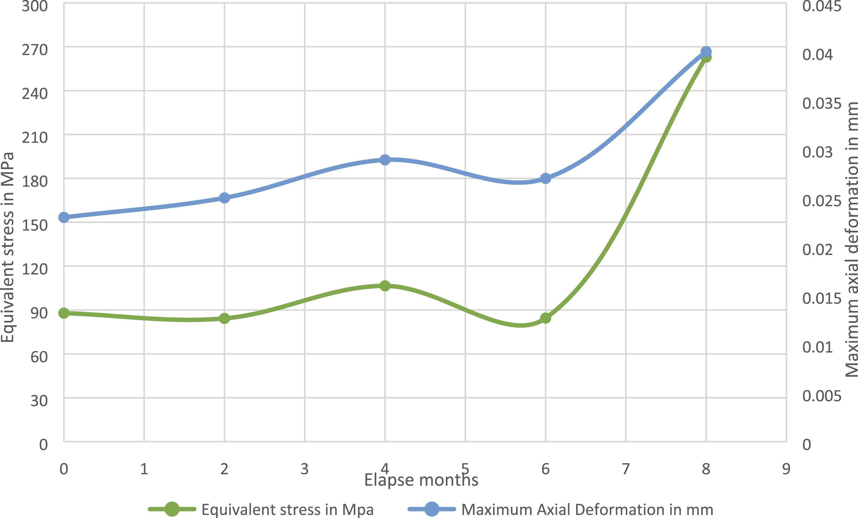
The limited axial interfragmentary deformation of bone segments near the fracture has a positive effect on the healing performance. Axial compressive load of 600 N generates limited axial deformation and stress in the LELCP within the safe limit even up to 6 months of continuous degradation because of the addition of ladder-type embossed structure. Overall, LELCP has been observed to perform reasonably well for commonly occurring axial compression loads and is superior to LCP even after sustained degradation.
Role and behaviour of screws
Orthopaedic implant screws have a major role to play as intermediate elements that transfer the movement/load from the bone to the implant plate. In this work, when axial compressive loads were applied on the bone having bonded screws (locking screw’s head with the male threads tightening on the plate’s UTCHs female threads) then bone starts exhibiting axial deformation in an inward direction (near the fracture location) and screws transfer loads via their heads to the plate on UTCHs. During implantation, the screw head’s complete surface area comes in contact with the plate’s complete thickness via UTCHs. During loading, major impact comes on the base diameter of the screw (just below the head). This region generates a higher stress concentration on the screw, as is shown in Figure 12(a). After the plate degrades uniformly from both sides (upper and lower surface) with accompanying reduction in thickness, major stresses start coming on the head surface of the screw which reduces overall stress concentration even after continuous degradation, as is shown in Figure 12(b). Deformed and stressed forms of meshed screws near the middle of the plate under UTCHs with (a) LELCP (without degradation), and (b) CD-LELCP (after 4 months or 1.33 mm reduced thickness) of continuous degradation).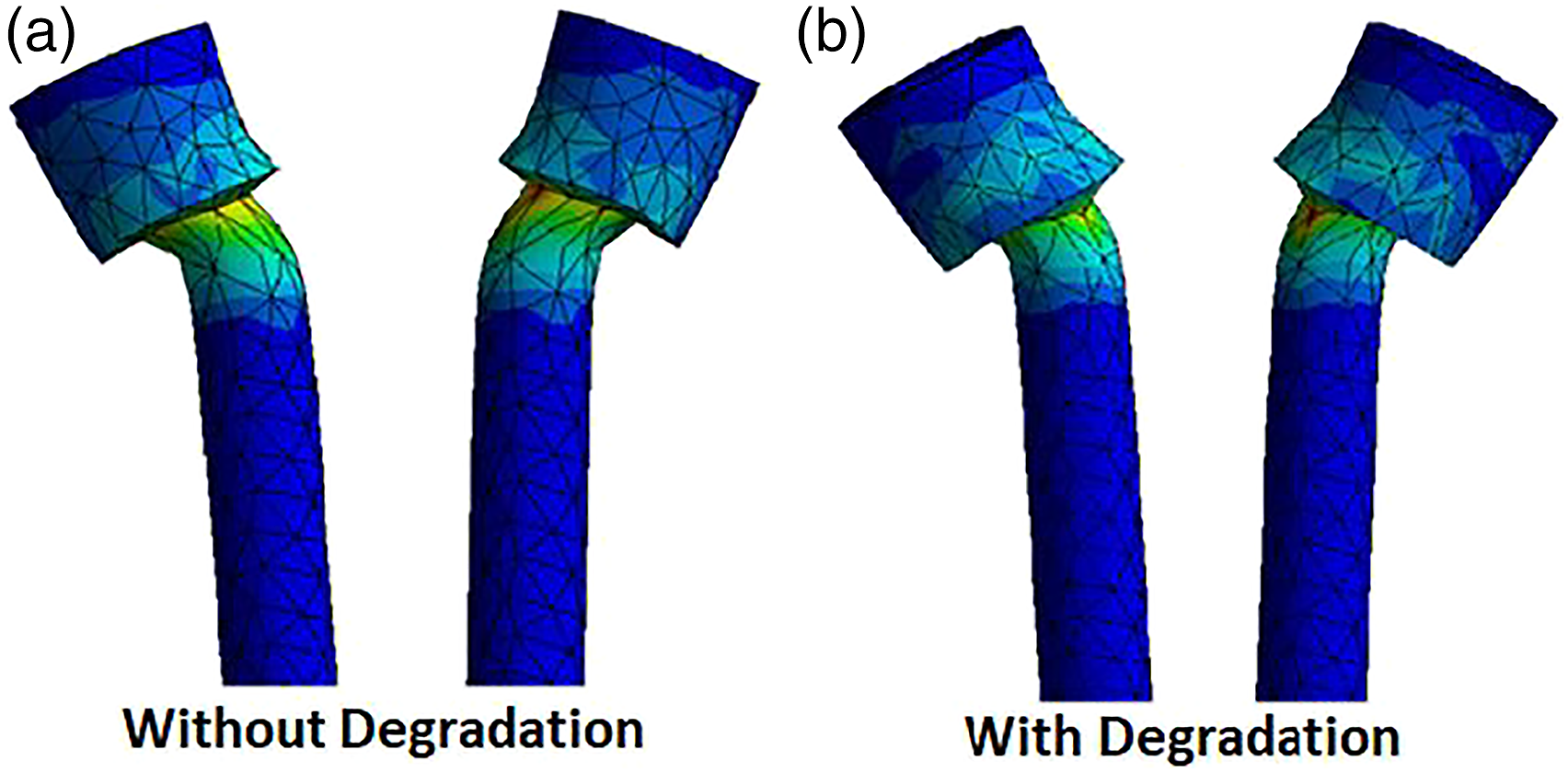
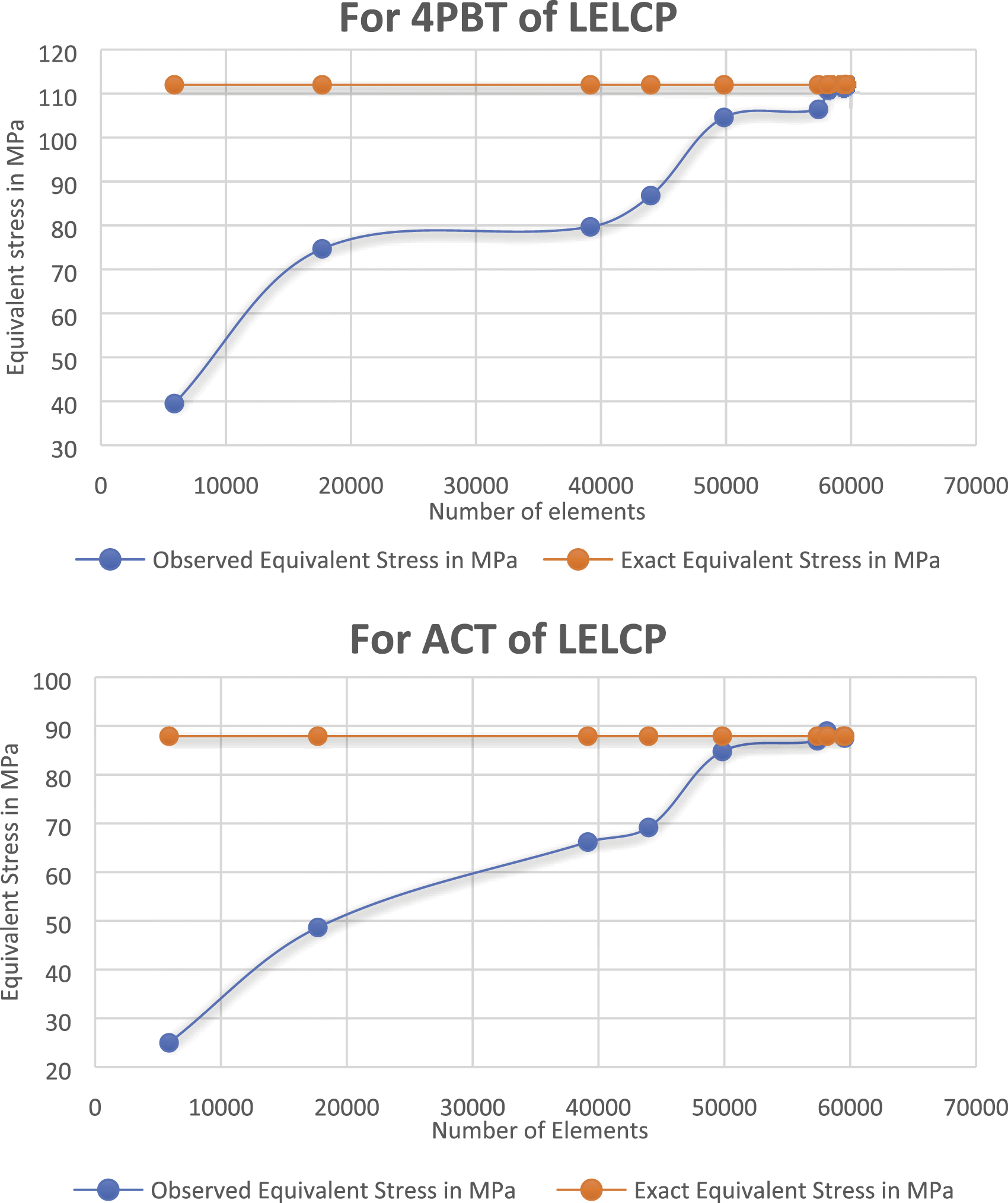
Stress generated on the screws starts diminishing after the start of continuous degradation but stress concentration starts increasing continuously on the UTCHs of the plate after a reduction in thickness. Figure 13 shows the effect of axial compressive stress on the inner edge of UTCHs after 6 months of usage of CD-LELCP. Due to this higher stress concentration, LELCP has higher chances of tearing when subjected to a high load. After 3–6 months of healing, the partially healed bone also starts offering some mechanical support. Deformed, meshed and stressed forms of UTCHs after 6 months (2 mm reduced thickness) of CD-LELCP during ACT. Convergence plot for LELCP design when observed with equivalent stress during 4PBT and ACT.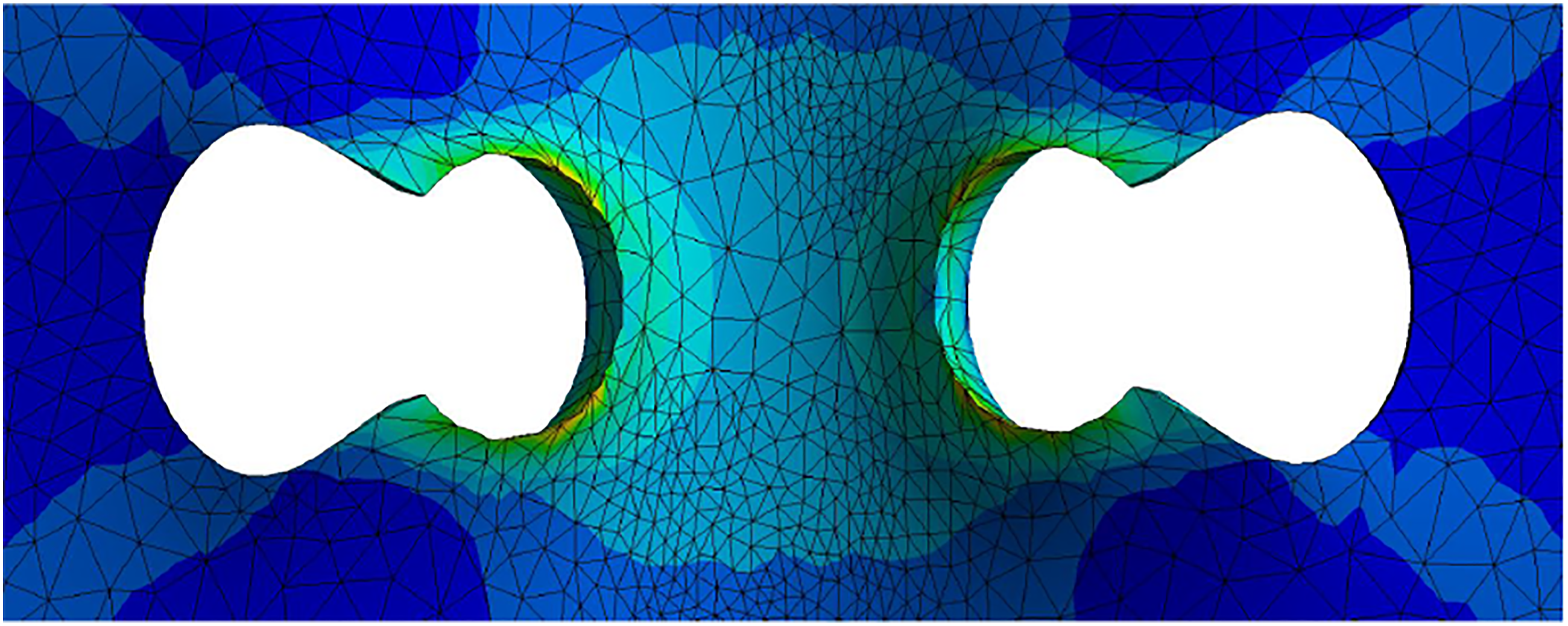
Overall, LELCP appears to be significantly superior in terms of mechanical performance for equivalent stress (von – Mises) and total deformation occurring parameter when used with similar biodegradable materials (Mg-alloys).
Mesh convergence plot and simulation
The convergence plot is used for evaluation of the accuracy of results generated through FEM with respect to real-time surgical simulations in accordance with the number of elements actually used for the plate having a specific geometry. The number of elements affects the results due to discretization error if the number of elements chosen does not correspond to the optimal number of elements. The most optimal mesh is identified by using an adequate number of elements that provide nearly stable results. For both tests, the convergence plot has been prepared for LELCP to check the exactness of the result. This convergence plot is shown in Figure 14, for the identification of the most optimal mesh where the most optimal mesh for the LELCP plate is found to have 59,557 elements.
Recommendations and future prospects
An ideal biodegradable implant plate must degrade in accordance with the standard time frame corresponding to the healing process when provided mechanical support that ensures adequate gap and alignment between segments of fractured bone. 1 As per assumptions and observations, LELCP must be safely stay put up to a maximum time duration of 6 months for routinely occurring loads (assuming an approximate biodegradation rate of 4 mm/year and uniform degradation). Simultaneously, bone healing may take about 3–6 months to achieve adequate mechanical strength that is sufficient to provide partial support and avoid stress shielding of newly generated bone. Any biodegradable implant plate must be tested in human beings (or in vivo) for a more accurate measure of the biodegradation rate which can help in predicting the expected time taken for complete degradation. It must completely degrade or disappear inside the body within the standard time frame without any undesirable effects. Every biodegradable material offers a different biodegradation rate due to influencing factors like blood flow rates, age groups, fracture sites and observation times. 35 Therefore, by choosing the best mechanically performing biodegradable material, that is, Mg-alloy, LELCP design can be tested in animals or human beings according to bone type and size. All these parameters can be combined together to develop a broad variety of implant plates where according to different biodegradation rates of biodegradable materials, dimensions can be predicted for various age groups, fracture sites, fracture types, etc.
Conclusion
To achieve enhanced mechanical capability with a biodegradable implant plate made of Mg-alloy, the design of the LCP was upgraded by adding semi-circular filleted embossed structures of the laddered type as LELCP. LELCP and LCP were mechanically tested by 4PBT and ACT using FEM, where LELCP was found to have low equivalent stress that compared to the corresponding values for LCP only about 26% (4PBT) and 10.4% (ACT), respectively. Similarly, the maximum vertical and axial deformations were also found to be 33% and 6% higher in LCP than in LELCP, respectively. In addition, the degraded forms of LELCP (CD-LELCP) were safe for both tests, with limited deformation at 2 months and 6 months, respectively. Overall, mechanical performance is significantly improved, where there is no significant difference in cross-section of LELCP from LCP, but this difference in cross-section increases proportionally in CD-LELCP after continuous degradation, which provides additional mechanical support. The reason for all this is the laddered embossed structure which helps to avoid stress concentration on the LELCP after a continuous reduction in thickness mainly due to uniform continuous degradation. Overall, the laddered embossed structure provides superior mechanical capability to LELCP, which can be used as an alternative to LCP for more suitable biodegradable implant plates after necessary validation using animal/human trials.
Footnotes
Acknowledgement
They are thankful to Maulana Azad National Institute of Technology (MANIT), Bhopal (INDIA), for the facilities extended.
Declaration of conflicting interests
The author(s) declared no potential conflicts of interest with respect to the research, authorship, and/or publication of this article.
Funding
The author(s) received no financial support for the research, authorship, and/or publication of this article.
Ethical Approval
Not required.
