
Abstract
The engineering of tracheal substitutes is pivotal in improving tracheal reconstruction. In this study, we aimed to investigate the effects of biomechanical stimulation on tissue engineering tracheal cartilage by mimicking the trachea motion through a novel radial stretching bioreactor, which enables to dynamically change the diameter of the hollow cylindrical implants. Applying our bioreactor, we demonstrated that chondrocytes seeded on the surface of Poly (ε-caprolactone) scaffold respond to mechanical stimulation by improvement of infiltration into implants and upregulation of cartilage-specific genes. Further, the mechanical stimulation enhanced the accumulation of cartilage neo-tissues and cartilage-specific extracellular macromolecules in the muscle flap-remodeled implants and reconstructed trachea. Nevertheless, the invasion of fibrous tissues in the reconstructed trachea was suppressed upon mechanical loading.
Highlight
1. The novel radial stretch bioreactor mechanically engineered the cell infiltration and distribution into the tubule scaffolds, via increasing the formation of interconnected micropores, possibly. 2. The mechanical property of the chondrocyte-scaffold composites was strengthened after the dynamic stretch incubation. 3. The expression of the cartilage-related genes and the accumulation of sGAG were elevated in cellularized tracheal constructs with dynamic stretch engineering. 4. The mechanically chondrogenic induction effects of in vitro dynamic stretch engineering could be extended to the in vivo ectopic and orthotopic implantations.
Introduction
In patients with esophageal cancer, laryngeal cancer, and tracheal defects, the reconstruction of trachea remains a challenge in current clinical practices. This is because most patients with long-segment tracheal resection could not tolerate conventional primary end-to-end anastomosis due to high tension at the anastomosis site.1–4 In order to achieve the unique hollow cartilage structure and functional layer of pseudostratified epithelium, the implanted replacement must possess adequate mechanical support while achieving proper biocompatibility for tissue growth.
Trachea substitutes have resulted in airway obstruction with collapse and stenosis or inadequate biocompatibility that results in poor vascularization and tissue degeneration. 4 Direct tracheal repair with synthetic materials of solid or porous prosthesis has been hindered by unacceptably high morbidity due to subsequent severe stenosis and narrowing.5–7 Decellularized allografts requiring no immunosuppression or growth factors may benefit those with diverse airway diseases, but the lack of proper vascularization results in degeneration or shortening of the transferred tracheal or aortic allografts.8–10 Complete tracheal transplantation demands proficiency in surgical techniques to maintain the complex systems of blood supply.11,12 Prolonged use of immunosuppressive therapy and a scarcity of matched donors further limit suitable candidates. Replacing the trachea with autologous tissue composite could circumvent chronic inflammation or infection as seen with synthetic materials.13,14 Nevertheless, free fasciocutaneous flaps require either external prosthesis or cartilage struts to replicate the trachea ring supports.12,15,16 The absence of mucociliary clearance within the tissue-engineered neo-trachea (TET) may increase the need for aggressive postoperative management of bronchial secretions.17,18 The pre-vascularized TET of both cartilage structural support and functioning mucociliary epithelium thus became a promising alternative to tracheal replacement.19,20 A recently published case of airway replacement with a tailor-made bioartificial nanocomposite previously seeded with autologous bone marrow mononuclear cells via a bioreactor has demonstrated successful transplantation of 5 postoperative months. 21
Whether natural or synthetic, materials with sufficient mechanical strengths, slow biodegradation rates, low bio-toxicities, and good bio-compatibilities could be converted into scaffolds that facilitate chondrocyte growth, maintain the cylindrical structure, and preserve luminal patency.20–24 However, preparing a tissue-engineered trachea continues to be expensive and time consuming. 25 Therefore, increasing chondrocyte growth and differentiation within the polymeric scaffolds is critical to accelerate tracheal cartilaginous tissue formation and shorten the preparation time prior to reconstruction.
The dynamic environment was found to be an important signal for cartilage tissue engineering.26–30 A dynamic environment could facilitate the infiltration of oxygen and nutrients into the inner scaffold, thus promoting tissue regeneration. 31 However, there are still limitations in the bioreactors for tracheal cartilage tissue engineering. Spinner-flask bioreactors have been demonstrated to improve nutrient delivery in the scaffolds, but the cartilage constructs grown in spinner-flasks were only 0.5 mm in thickness which was too thin for clinical use. 32 In addition, cells grew mostly on the surface of the scaffolds in spinner flasks, like what happens in static cultivation. The rotating-wall and flow-perfusion bioreactors provided a more homogenous distribution of cell growth inside of scaffolds. However, they were methodologically developed to help cells seeding into the scaffold instead of mimicking the natural environment of cartilages. After a short term of bioreactor-assisted cell seeding procedure, the constructs still required either mechanical stimulation in combination with a mechanical bioreactor or ectopic cultivation in vitro for cartilage formation. Since tensile strain has been proven to facilitate mesenchymal stem cells differentiating along the chondrogenic lineage on a dish,32–34 the strain bioreactors were used for cartilage formation. However, a clamp was required for strain bioreactors to fix the constructs and transfer the tensile force to cell-seeded constructs, which in turn limited the direction of stimulation and shape of constructs. The compression bioreactor was also widely used in cartilage engineering.35–37 Hydrostatic pressure bioreactors simulating the dynamic stretch of knees could also apply a mechanical stimulus to cell-seeded constructs, but they were neither intended nor suitable for stimulation of O-shaped hollow tracheal constructs. 38
The purpose of the current study is not to achieve an ideal design and the best mechanical performance of dynamic stretch bioreactor, but to determine whether the dynamic stretch bioreactor is able to improve the efficacy of cellular chondrogenesis and to accelerate fabricating the TET. In this study, treatment of constructs with dynamic stretch increased the infiltration of chondrocytes into scaffolds, accelerated the formation of neo-cartilage tissues, and relatively revealed an effect of reducing the time of in vitro cultivation. Moreover, the beneficial effects of dynamic stretch stimulation in vitro were long-lasting and sustainable in the ectopically implanted TET and reconstructed trachea.
Materials and methods
Chemicals and reagents
Dulbecco’s modified Eagle’s medium (DMEM), fetal bovine serum (FBS), Antibiotic-Antimycotic, type I collagenase (17,018-029), and Insulin-Transferrin-Selenium (ITS) (41,400,045) were purchased from Gibco (USA). Other compounds that did not indicate the manufacturer are purchased from Sigma-Aldrich.
Poly (ε-caprolactone) scaffold preparation
The Poly (ε-caprolactone) (PCL) (Mn∼80,000) hollow scaffolds were fabricated using solvent casting/particulate leaching method according to the previous study.23. In brief, PCL: NaCl crystals of 1:8 (w/w) were blended with chloroform. The blend was shaped by a tubule mold (5 mm in height, 8 mm in inner diameter, and 11 mm in outer diameter) followed by drying and washing with deionized water. Scaffolds were disinfected with 75% ethanol, washed with sterile deionized water, and dried for storage.
Radial stretch bioreactor
The dynamic stretch bioreactor was designed in the expansion/relaxation motion loop of O-shaped hollow scaffolds. Through a hydraulic pressure system, cyclic expansion/relaxation motion loops were generated to treat the hollow constructs. This bioreactor consisted of a hydraulic pressure system and incubation chamber (Figure 1(A and Bd)). The motor in the hydraulic pressure system rotated an eccentric wheel, which transmitted the pressure from the hydraulic piston to the silicone tube in the incubation chamber (Figure 1(Ba)), and caused the enlargement of the silicone tube. Cyclic expansion/relaxation motion loops of silicone tube stimulated the hollow constructs in the incubation chamber (Supplementary Video). The incubation chamber of dynamic stretch (Figure 1(Bb)) or static (Figure 1(Bc)) group was, respectively, connected or unconnected to the bioreactor. Generally, the radial stretch bioreactor runs continuously unless it took a break every 2 days to refresh the medium. Structure of dynamic stretch bioreactor and incubation chamber of scaffolds encapsulated in chondrocytes. The 2D structure of the dynamic stretch bioreactor consisted of a hydraulic pressure generation system and a scaffold cellularization incubation chamber (A). To construct an incubation chamber, an expandable silicone tube was engaged with a copper pipeline (Ba). Scaffolds deposited on the silicone tube and incubation chamber were constructed, filled with culture medium, and incubated in the CO2 incubator (Bb). One incubation stayed in the rack as a static group, and another incubation chamber was lined with the hydraulic pressure generation system (Bc) as the dynamic stretch group. C. The stability performance of the pressure cycles continually produced by dynamic stretch bioreactor for 7 days. An insert represented the enlarged figure of the pressure curve in a period of 14 s.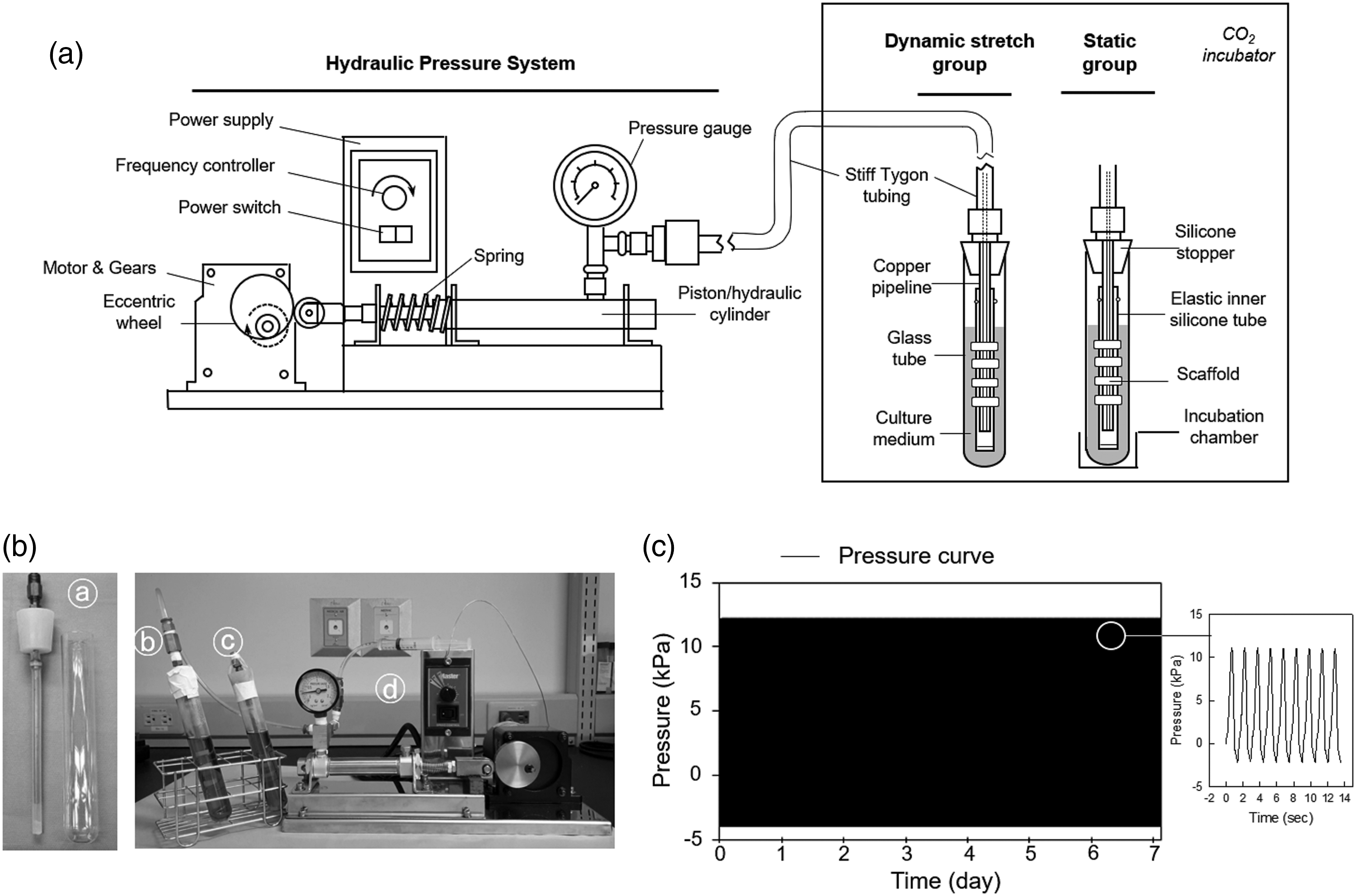
The measurement of pressure on silicone tube of bioreactor
The silicone pressure data was acquired with a strain measuring unit (EDX-10B and EDX-11A, Japan) and DCS-100A software (Kyowa). Data of the dynamic pressure were acquired at frequencies of 30 Hz. To study the long-term stability of the pressure generated, the bioreactor continuously runs at working pressure for 7-day. For adjusting the pressure, the volume of water in the bioreactor could be controlled by water injection or retrieval. Higher volume of water, higher pressure produced by the bioreactor
Isolation and culture of rabbit chondrocytes
All animal procedures according to the “Guide for the Care and Use of Laboratory Animals” after approval by the Institutional Animal Care and Use Committee of Chang Gung Memorial Hospital (Approval No. 2,012,121,808, date 22 Oct 2016). The chondrocytes were isolated from auricular cartilage of rabbits as previously descripted.23 The chondrocytes were cultured in growth medium (DMEM with 10% FBS and 1% Antibiotic-Antimycotic) at 37°C in a 5% CO2 incubator, and medium was refreshed 2–3 day.
Incubation of cellularized implants in the dynamic stretch bioreactor
Allogeneic chondrocytes (passage 2–3) were seeded on the surface of scaffolds at the density of 2 × 10⁴ cells per mm2, incubated in a CO2 incubator for cells adherence on scaffolds for 45 min, added the growth medium, and cultivated for 7-day. Constructs were held on the silicone tube of the incubation chamber which filled with chondrogenic defined medium (DMEM with 1X ITS, 5.33 μg/mL linoleic acid, 1.25 mg/mL bovine serum albumin, 100 nM dexamethasone, 50 μg/mL ascorbate, 40 μg/mL L-proline, 1% Antibiotic-Antimycotic, and 5 ng/mL TGFβ1 (100-21, Peprotech, USA).21,22 Both dynamic and static group incubation chambers were cultivated for 7 days, the medium was refreshed every 2 days. To determine whether the medium turns acidic in closed incubation chambers, the pH value of the cultured medium was measured daily.
Micro-computed tomography analysis
After fixing with 4% buffed paraformaldehyde, scaffolds or constructs were imaged with a micro-computed tomography (CT) scanner μSPECT/CT (Mediso, Hungary). The Hounsfield Unit (HU) is a quantitative presentation of radio density when interpreting CT images. The HU is calculated based on a linear transformation of the attenuation coefficient of the X-ray, where distilled water is defined to be zero HU and air is defined as −1000 HU. The higher density tissue was associated with greater X-ray attenuation, higher HU values, and vice versa.39,40 In micro-CT grayscale images, photographs converted to 8-bit grayscale, and the gray values of the region of interest were measured with ImageJ software version 1.39.
Scanning electron microscope
The ultrastructure of scaffolds was illustrated by Scanning electron microscope (SEM), both the surfaces and cross-sections were examined. The cross-sections were obtained by fracturing after freezing in liquid nitrogen. Samples were washed thrice with PBS (pH 7.4) and then fixed overnight with 2% glutaraldehyde in PBS at 4°C. And then the specimens were rinsed with deionized water 4 times, followed by dehydration using an alcohol gradient and substitution in isoamyl acetate solution twice, for 20 min each. The specimens were further dried with Balzers carbon dioxide critical point dryer 030 (Balzers, Liechtenstein) and coated with gold particles in a sputter coater (Hitachi, Tokyo, Japan) before examination using an SEM (SU8220, Hitachi) at 250–500× magnification with an accelerating voltage of 5 kV. Similar procedures were implemented to compare the surface morphology of polymeric scaffolds and pore sizes of scaffolds were measured in SEM images using NIH ImageJ software. Moreover, the numbers of the micropore in constructs of static and dynamic groups were analyzed with the function of the” Analyze Particles” in the ImageJ software.
Mechanical examination
The axial and radial compression examinations were reported previously.41,42 In brief, the axial and radial compression examinations were conducted using a universal testing system (Model QC-513B1, Cometech, Taiwan) with the loading capacity of 500 N and 500 N and 100 N, respectively, and the loading precision of ±0.5%. In the tests, the displacement was controlled at a speed of 0.2 mm/min. A software QCtech (Cometech) simultaneously acquired the displacement and stress information. Before starting the test, the load and displacement were reset to zero, the mechanical properties of the fabricated scaffolds, cell-free constructs, static group constructs, and the dynamic stretch group constructs were measured in uniaxial and radial compressions methods following the above condition. Data were represented graphically as load versus displacement curves.
RNA extraction and RT-qPCR analysis
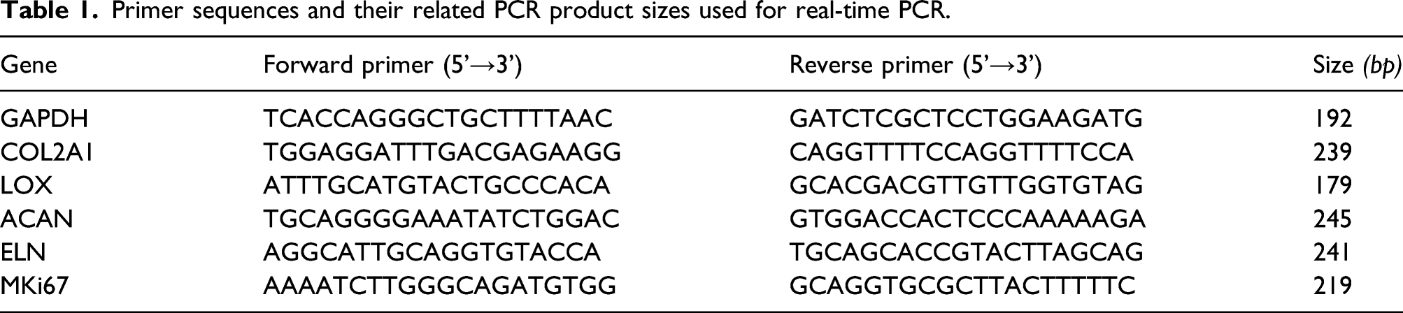
Total RNA was extracted with REzol isolation reagent (Protech, Taipei, Taiwan) according to the instructions of the manufacturer. Briefly, RNA was treated with RNase-free DNase I (TaKaRa, Kyoto, Japan), followed by determining the concentration and purity of RNA at the 260 nm and 280 nm of the UV spectrum (Synergy LX, BioTek). RNA samples were reverse transcribed to cDNA with TaqMan Reverse Transcription Reagents (Applied Biosystems, Foster City, CA) using random primers. Real-time PCR was performed with SYBR Green-based quantitative PCR (Thermo Fisher Scientific) according to the manufacture’s instruction. For amplification of specific genes, 20 ng of cDNA was used in each reaction, and glyceraldehyde 3-phosphate dehydrogenase (Gapdh) gene was used as the reference gene. To reduce the high abundance effect of the Gapdh gene on amplification, cDNA diluted 1:10 with ddH2O (2 ng) was used in an amplification reaction. Relative fold change of gene expression was calculated in the 2-(ΔΔCt) method, 43 where Ct is the threshold cycle, which is the fractional cycle number at which the amount of amplified target reaches a definite threshold.
Primer sequences and their related PCR product sizes used for real-time PCR.
Glycosaminoglycans analysis
The content of Glycosaminoglycans (sGAG) in the samples was measured with the reaction of 1.9-dimethyl-methylene blue (DMMB). 44 Constructs cut into small pieces were suspended in digestion buffer (50 mM sodium phosphate, 2 mM cysteine, 2 mM EDTA, and 5 U papain, pH 6.5) and incubated at 65°C overnight, followed by centrifugation and stored at −20°C. For sGAG estimation in samples, 50 μL of supernatant was reacted with 600 μL of DMMB solution (16 μg/mL DMMB, 3 mg/mL glycine, and 2.5 mg/mL NaCl, pH3), and optical density was read at 530 nm using a spectrophotometer (Synergy, BioTek, USA). Water 50 μL blended with 600 μL of DMMB solution as a blank reference. Chondroitin sulfate-B (Sigma-Aldrich) was applied to generate a standard curve, and the amount of sGAG was normalized to the weight. 45
Pre-vascularization of TET with pedicled muscle flap
The animal experiment was planned, grouped, implemented, examined, and recorded in Figure S1. Pre-vascularization of TET was described previously.22,27 In brief, anesthetized rabbits were operated, a pedicled cutaneous maximus muscle flap based on the lateral thoracic vessels was elevated (Figure 2(A)) to wrap 2 constructs with a silicone tube (Figure 2(B)). Rabbits were i.m. injected with Cefazolin 0.25 mg/kg in the first 3 days after the operation. Tissue-engineered neo-trachea (Figure 2(C)) was examined on day 14 and 28 after the operation, and the silicone tube was removed (Figure 2(D)). Tissue-engineered neo-tracheas were evaluated in histological examinations. In addition, the engineered TET at postoperative day 14 was prepared for the following tracheal transplantation (Figure 2(E-H)). Surgery procedure. A pedicled cutaneous maximus muscle flap (A) was elevated to roll tandem cell-scaffold constructs (B). After 1 week, the pedicled construct (C) formed a vascularized tubule TET (D). Then, pedicled TET was trans-positioned to where is closed to the trachea (E). After immobilizing the trachea (F), a trachea defect was created (G), which was repaired with pedicled TET (H). After 4 weeks, the reconstructed trachea was explanted (I). MP, muscle pedicles. TET: tissue-engineered neo-trachea.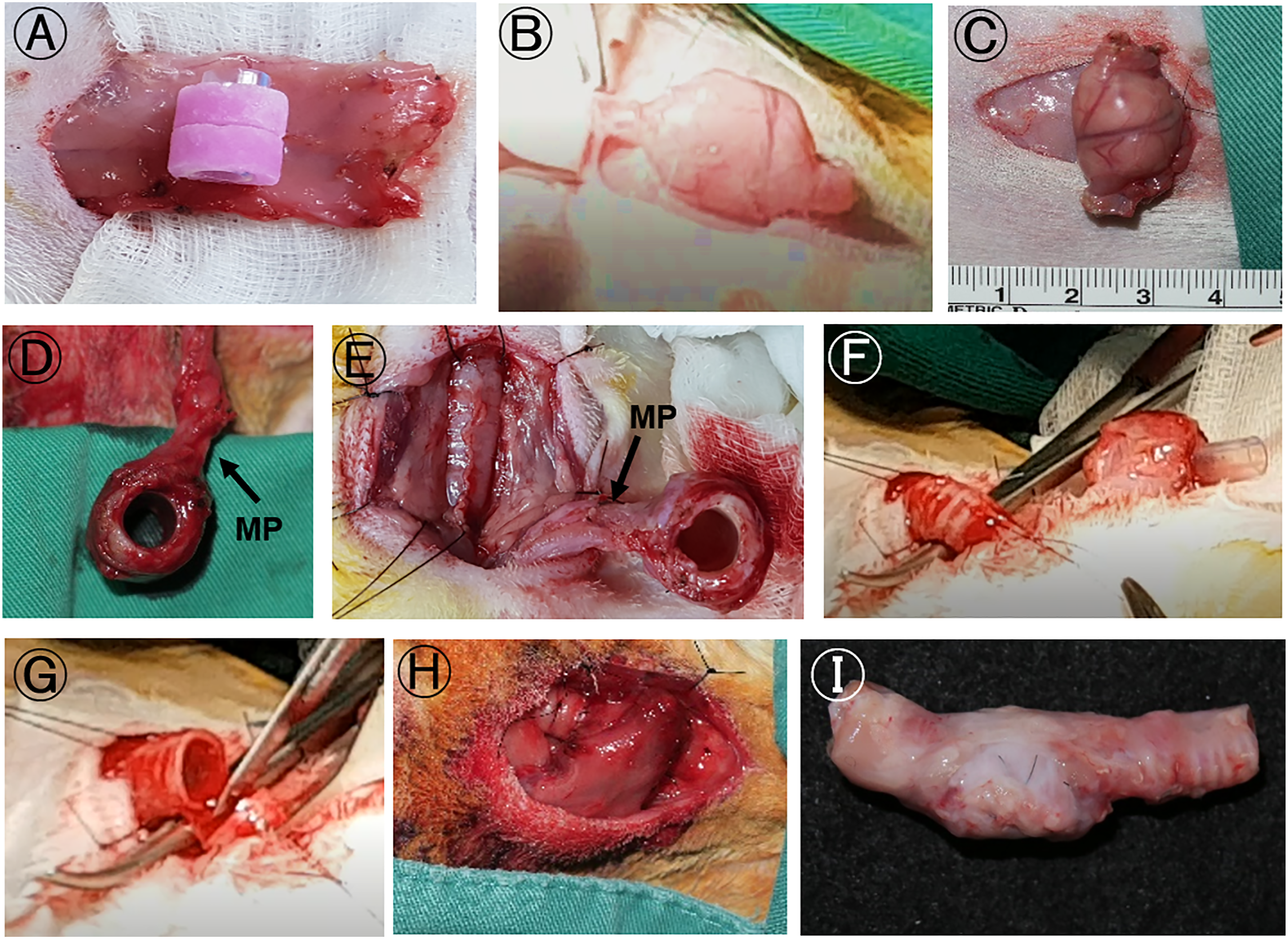
Tracheal transplantation of vascularized TET
The tracheal defect replaced with the pre-vascularized TET (Figure 2(D)) was trans-positioned from the upper abdominal wall to where is closed to the trachea (Figure 2(E)). The tracheal defect created by resection (Figure 2(F)), followed by end-to-end anastomoses (Figure 2(H)). Two weeks after tracheal transplantation, the silicone tube was removed with tracheostomy when rabbits were under anesthetic condition. On day 28 post-tracheal transplanted, the reconstructed trachea (Figure 2(I)) was disconnected from animals and evaluated by histological and immune-histochemical staining.
In Figure S1, about 10% of rabbits were expired after tracheal transplantation, some reasons might associate with animal expire found and discussed with the veterinarian of the animal center. (1) Sputum accumulated in the trachea without mucus clearance function might be caused by luminal silicone stent, which resulted in suffocating of transplanted animals (n = 2); (2) Airway narrowing caused by the formation of the foreign body granuloma in the anastomotic location (n = 1); and (3) Abnormal licking of rabbit hair causes anorexia. It was observed that the stomach is full of hair and villi after anatomy (n = 1).
Histological analysis
The implants were fixed in buffered formalin for 24 h, then dehydrated, embedded in paraffin, and sectioned. After deparaffinization and rehydration, tissue sections were stained with kits of safranin O, alcian blue (StatLab, USA), Masson’s trichrome (StatLab), and Picrosirius red (StatLab) according to manufacturer’s instructions. Sections were mounted with mounting medium and observed under a light microscope Axio Scope (Zeiss, Germany). Photographs presented in RGB color mode were split into R, G, and B images, in which one of the images would be chosen as the target color image according to what target would be analyzed using ImageJ. In the Alcian blue-stained slides, the area and mean gray value of the blue dye portions (as cartilage-related proteoglycans) were measured. In the Masson trichrome stained slides, the area and mean gray value of the blue dye portions (as collagen fibers) were measured. In the Safranin O-stained slides, the area and mean gray value of the red dye portions (as cartilage-related proteoglycans) were measured using ImageJ software. The integrated density was auto-calculated into the product of area and mean gray value of the by ImageJ.
Immunohistochemistry staining
Deparaffinized and rehydrated tissue sections were subjected to antigen retrieval with sub-boiling citric acid buffer (10 mM sodium citrate, 0.05% Tween 20, and pH 6.0). After incubating with H2O2 solution for 20 min, sections were rinsed with PBS plus 0.1% Tween 20 (PBST), incubated with block solution (X0909, Dako), and stained with anti-CD31 (ab24590, abcam), anti-collagen II (ab150771, abcam), anti-major histocompatibility complex (MHC) class I (clone H58 A, NBP2-61,002, Novus biologicals, CO), anti-MHC class II (clone TH14 B, NBP2-61,026, Novus biologicals), and Control Mouse IgG (I-2000-1, Vector laboratories, Burlingame, CA). Finally, Real EnVision detection system (K5007, Dako) was subjected to incubate sections for 1 h, and slides were mounted with a mounting medium (A1025/500, Assistant). To analyze the integrated density, the area and the mean gray values of the brown color of the DAB regions were measured using ImageJ.
Statistical analysis
Data were expressed as mean and standard deviation (SD). Statistical analyses were conducted by Student’s t test or one-way ANOVA. Values of p < 0.05 were considered significant.
Results
Properties of novel dynamic stretch bioreactor
The overall experimental design of the current study was depicted in Figure S2. The dynamic stretch bioreactor was established and manufactured by our group, as shown in Figure 1(A) and (Bd). The working bioreactor frequency was critical for stimulating cells in the scaffolds. 27 In this study, the mechanical reaction dynamic stretch bioreactor frequency was set at 35 cycles/min by mimicking the respiratory rate (30–60 times/min) of healthy New Zealand white rabbits in normal conditions. This rate had been reported in the model information sheet by Charles River Laboratories (Wilmington, MA). To understand the working stability of the radial stretch bioreactor, the pressure of the silicone tube was monitored continually for 7-day, as illustrated in Figure 1(C), the dynamic pressure was stable, which represents the pressure forming machinery of the radial stretch bioreactor was stable and durable.
Effects of dynamic stretch on cell distribution in scaffolds
To study whether mechanical stimulation radial stretch of constructs can improve cell infiltration and distribution in the scaffold, the tubule cell-scaffold composites were treated with and without the radial stretch in various pressures, and engineered constructs were imaged with micro-CT and shown in the thermograph-like according to the HU scale (Figure 3(A)). Hounsfield unit is a quantitative measurement of radio density in micro-CT images. The static group constructs (Figure 3(Af)) displayed a surface radio-absorbance. In the dynamic stretch group, the cell distribution (Figure 3(Ag-j)) was observed with obviously increased when the maximal stimulatory pressure ≥6 kPa (Figure 3(Ab-e)). In accordance with the HU scale, the engineered constructs have the highest HU when the mechanical stimulation pressure is around 11 kPa (Figure 3(Ac, h)). Here, we would like to emphasize that the cells in the constructs of either static or dynamic groups would not have an intrinsic X-ray attenuation ability to be visualized by micro-CT images.
46
However, the X-ray attenuation in this figure might reflect the deposition of ECM following migratory infiltration of the cells within the scaffold. Dynamic stretch stimulated the distribution of chondrocytes in the porous scaffolds. A. Mechanical stimulation increased chondrocytes distribution in the cell-scaffold constructs. The cyclic change of the pressure (Aa-e) measured on the silicone tube and the responding cell distribution (Af-j) in the static group (a, f) and dynamic stretch groups (Ag-j). Micro-CT images (Aa-e) displayed in the color format according to the HU scale. B. Micro-CT images of the tissue-engineered constructs displayed in grayscale responded to the mechanical stimulation. Constructs of the static group (Ba-c) and dynamic stretch group with various maximal pressures at 6- (Bd-f), 11- (Bg-i), 20- (Bj-l), and 30-kPa (Bm-o). Three representative images in one group were shown. The cell-free constructs of the static group as negative control were shown in grayscale (Bp) and HU scale formats (Bq). The gray values of the micro-CT images were measured (Br). Values represent mean ± standard deviation (SD). (n = 5–6). *p < 0.05 means a significant difference compared with the static group. At the end of the experiment, constructs were frozen sectioned. Cell nuclei were visualized by DAPI staining (C). The profiles of cell infiltration were indicated in the static group (Ca) and the dynamic stretch group (Cb). Scale bar (0.5 mm). At the end of the experiment, the diameter (D) and cell viability (F) of constructs in groups were measured with a digital caliper and MTT assay, respectively. Values represent mean ± SD. (n = 5–8). *p < 0.05 means a significant difference compared with the static group. The change of pH values in the cultured medium of both groups (G). Values represent mean ± SD. (n = 3). The red arrowhead means the beginning of static and dynamic stretch cultivation; blue arrowheads mean culture medium refreshed. HU: Hounsfield unit.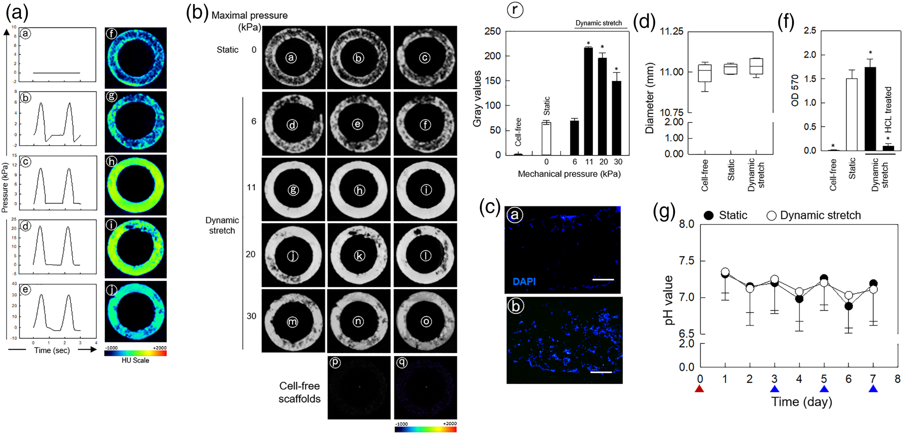
The tissue-engineered constructs of the static group (Figure 3(Ba-c)), the dynamic stretch group with various pressures (Figure 3(Bd-o)), and cell-free scaffolds (as a negative control; Figure 3(Bp)) were imaged with micro-CT and displayed in a grayscale format. The gray values were measured (Figure 3(Br)), a significant increase of the gray values was noted in constructs with dynamic stretch stimulation when pressure is more than or equal to 11 kPa (Figure 3(Bg-o and r)) compared to the static group. Moreover, the maximal pressure 11 kPa of the dynamic stretch was effective to stimulate cell distribution in the porous scaffolds (Figure 3(Br) and 3(C)). To determine whether the diameter of the constructs is changed after dynamic stimulation, the diameter of the cell-free scaffold, static group, and the dynamic stretch group was measured with a digital caliper. As shown in Figure 3(D), no significant difference was noted. In order to determine whether chondrocytes in the constructs are alive, the cell-free scaffold, static constructs of static and dynamic groups were cut into small pieces followed by MTT assay. Further, a construct of the dynamic group was treated with 5N HCl as a negative control. As illustrated in Figure 3(F), it was demonstrated chondrocytes in constructs in both static and dynamic groups were surviving. Since incubation chambers were sealing closed environments, the change of medium pH value was monitored every day in the process of either static culture or dynamic stretch treatment. As shown in Figure 3(G), the changes of pH value were stable and no significance was found between both groups.
Formation of the interconnected micropores in scaffolds
Scaffolds cultivated in static and dynamic stretch environments for 1 week were imaged with SEM. The averaged scaffold pore sizes created by NaCl crystals were 184 ± 83 μm and 194 ± 58 μm in the dynamic stretch and static group, respectively (Figure 4(A)). This indicated that scaffold pore sizes were not obviously different between the dynamic stretch and static groups. However, at higher magnification, a large number of interconnected micropores (10 ± 1.7 μm in size) were observed on the surface and inner section of scaffolds in both groups (Figure 4(Ae-h)). As illustrated in Figure 4(B), more amount of the micropores in the constructs of the dynamic group compared to the static group (Figure 4(B)). To understand whether the degradation of scaffolds is associated with micropore formation, the dry weight of scaffolds of the dynamic stretch and static groups was measured. No significant difference was noted between groups (Figure 4(C)). It is possible that the detached PCL little pieces stayed in the construct since the pore compartments in the scaffold were not interconnected well. Effects of mechanical stimulation on changes of micro-structure and mechanical properties of the constructs. A. The surface and internal cross-sections of tissue-engineered constructs of the static group (Aa, c, e, and g) and the dynamic stretch group (Ab, d, f, and h) were imaged with SEM. White arrowheads indicated the formation of micropores (Ae, f, g, and h). Scale bar (250 μm) in the photograph Aa, b, c, and d. Scale bar (150 μm) in the photograph Ae, f, g, and h. B. The number of micropores in each SEM field was calculated. Values represent mean ± SD (n = 9). * p < 0.05 means the statistical significance compared to the static group. C. The degradation rate of tissue-engineered constructs was examined in the measurement of the dry weight of constructs at the time indicated. Values represent mean ± SD (n = 10). The mechanical properties of the scaffolds in the axial (D) and radial (E) compressive modes. Moreover, the mechanical properties of the constructs in the cell-free, static, and dynamic stretch groups were measured in axial (F) and radial compression modes. Values represent mean ± SD (n = 3–5). a, p < 0.05 means a significant difference compared with the 25% strain of the cell-free group. b, p < 0.05 represents a significant difference compared with the 50% strain of the cell-free group. c, p < 0.05 means a significant difference compared with the 75% strain of the cell-free group. * p < 0.05 means a significant difference compared with the static group. SEM: Scanning electron microscope.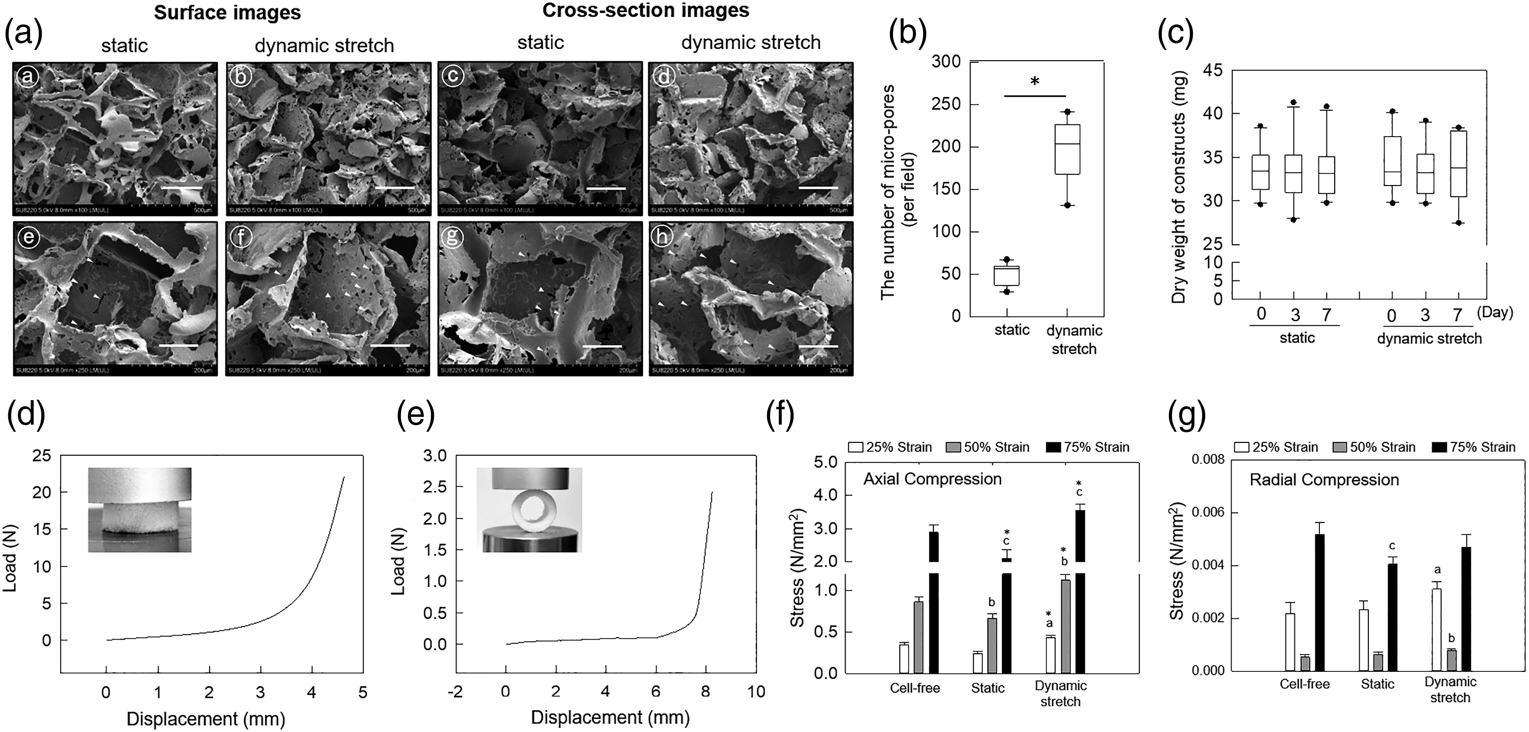
The mechanical properties of tissue-engineered constructs
The load versus displacement curves of the scaffolds with axial (Figure 4(D)) and radial (Figure 4(E)) compressive tests were performed. 47 In addition, the mechanical property of the cell-free, static, and dynamic stretch groups of constructs was measured in the axial (Figure 4(F)) and redial (Figure 4(G)) compressive modes. In the axial measurement, the mechanical property of the dynamic group obviously was stronger than cell-free and static groups (Figure 4(F)). In the radial compressive measurement, the dynamic stretch group constructs have a higher load at 25% and 50% strain, but not 75% strain than the cell-free group (Figure 4(G)). No significant difference in the load was found between static and dynamic groups in the radial compressive examination (Figure 4(G)).
The effects of conditioned medium on the synthesis of sGAG
The conditioned medium (CM) of static and dynamic stretch groups was individually harvested after removing cell debride via centrifugation at 5000 × g. The passage 5 chondrocytes plated into the 24-well plate were treated with either fresh growth medium, or the CM for 7 days, followed by safranin O staining. To understand whether releasing chondrogenic soluble factors mediates pro-chondrogenic dynamic stretch stimulation, the CM of the dynamic stretch and static groups were applied to incubate chondrocytes for a week. Safranin O staining profiles (Figure S3) showed the CM of the static group slightly increased sGAG production. The dynamic stretch group-CM, however, obviously increased the accumulation of sGAG macromolecules (Figure S3(C)).
Regulation of cartilage-related genes and production of sGAG in vitro
The expression of Col2a1, Acan, Eln, and Lox genes was increased in a time course fashion (Figure 5(B–E)). The expression of Sox9, Col2a1, Acan, and Lox genes was elevated significantly in the dynamic stretch group comparing to the static group (Figure 5(A–D)). In comparing the static group, the Eln gene expression was obviously elevated in the early phase in the dynamic stretch group (Figure 5(E)). The expression of Mki67 gene was no obvious difference between the dynamic stretch and static groups (Figure 5(F)). In addition, cartilage-specific extracellular matrix glycan sGAG was significantly elevated in the dynamic stretch group, comparing with the static group (Figure 5(G and I)). However, the amount of DNA was not obviously different between the two groups (Figure 5(H)). Expression profiles of the cartilage-related genes and sGAG macromolecules in the tissue-engineered constructs. Tissue-engineered constructs were cultivated in static condition (opened square) and expression levels of cartilage-related genes were indicated. Data presented the fold(s) change was normalized with Gapdh gene levels at the relevant time points. The expression profiles of Sox9 (A), Col2a1 (B), Lox (C), and Acan (D), Eln (E), and Mki67 (F) genes were illustrated. Values represent mean ± SD (n = 4). *p < 0.05. The concentrations of the sGAG/construct (G), of DNA/construct (H), and of sGAG/DNA (I). Values represent mean ± SD (n = 3). *p < 0.05. d1: day 1 after static/dynamic stretch cultivation. d7: day 7 after static/dynamic stretch cultivation. GAG: Glycosaminoglycans.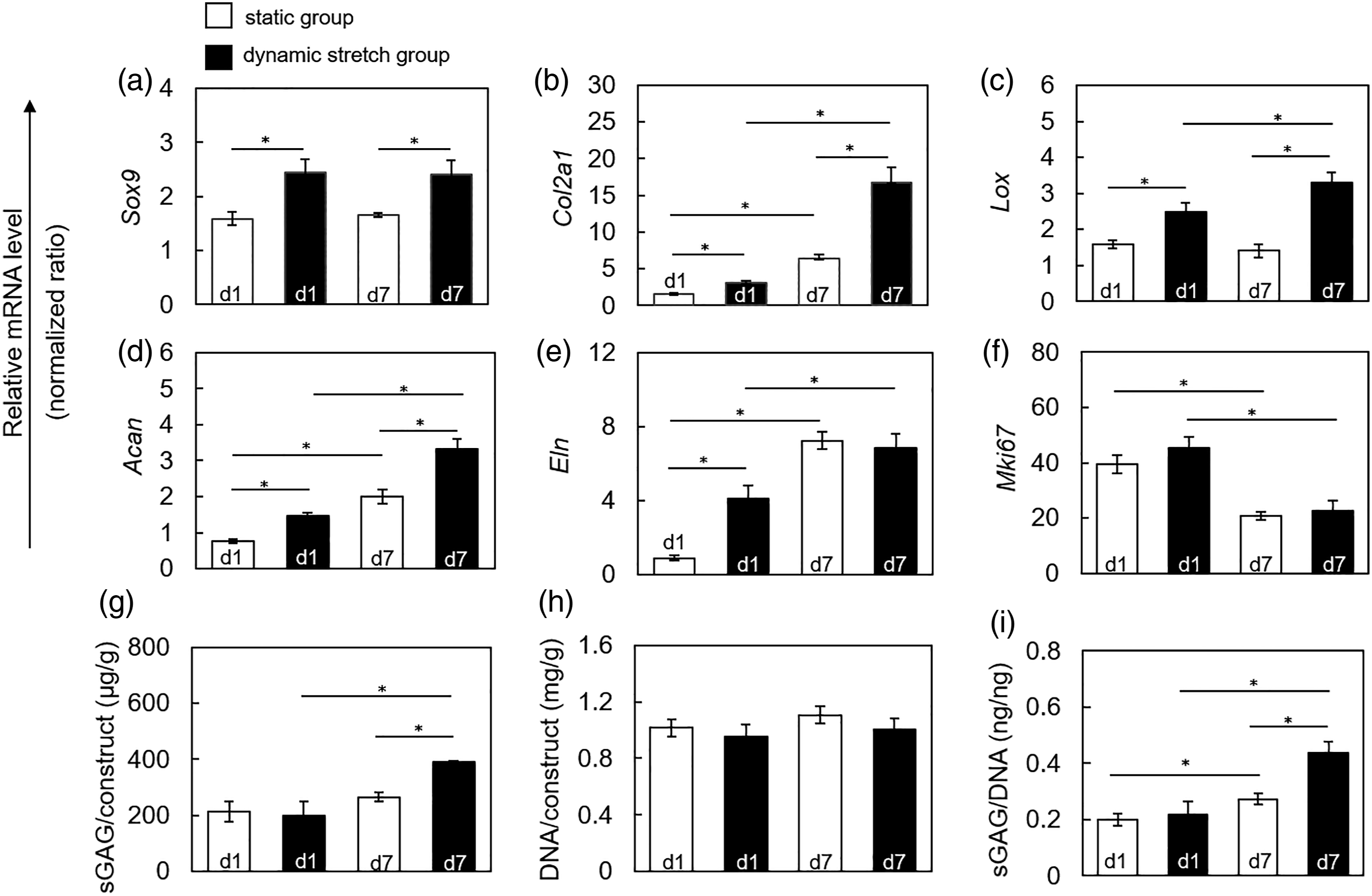
Histological evaluations of in vivo ectopic TET explants
The ectopic TETs were analyzed with histological and Immunohistochemistry staining (IHC) examinations. Alcian blue-stained (Figure 6(A)) and safranin O-stained (Figure S4(A)) cartilage sGAG macromolecules in TETs were time-dependently elevated and such trend was noted in both dynamic stretch and static groups (Figure 6(Ac, d)). However, the integrated density of Alcian blue-stained (light blue) cartilage-related proteoglycans was obviously increased in the TETs of the dynamic group compared to the static group (Figure 6(Ae)). The accumulation trend of Masson’s trichrome (Figure 6(B)) and Picrosirius red (Figure S4(B))-stained collagen macromolecular collagen fibers were increased in a time-dependent fashion in the individual group (Figure 6(Bc and d)). The integrated density of (dark blue) collagen fibers in the TETs of the dynamic group (Figure 6(Bd, e)) was significantly increased compared to TET of the static group (Figure 6(Bc)) TETs. Moreover, the expression of cartilage-specific COL II proteins was increased in a time-dependent manner in the individual group (Figure 6(Cc, d)). The integrated density of COL II was obviously increased in TETs of the dynamic stretch group compared to TET of the static group (Figure 6(Ce)). This suggested that the effects of the mechanical stretch stimulation of bioreactor in vitro could be extended to the ectopic TETs. Histological staining and ICH staining in the TETs. The TETs obtained from ectopic implants were stained with Alcian blue (A), Masson’s trichrome (B), and anti-COL II (C). TETs of the static (a, c) and the dynamic stretch group (b, d) were remodeled in muscle flaps for 14 days (a, b) and 28 days (c, d). Scale bar (500 μm) in the photographs. Scale bar (50 μm) in the inserts. The integrated density of each staining was analyzed with ImageJ (e). Values represent mean ± SD (n = 3–5). *p < 0.05. AB, alcian blue staining; MT, Masson’s trichrome staining; anti-COL II, anti-type 2 collagen IHC staining; IntDen, Integrated density. TET: tissue-engineered neo-trachea; IHC: Immunohistochemistry staining.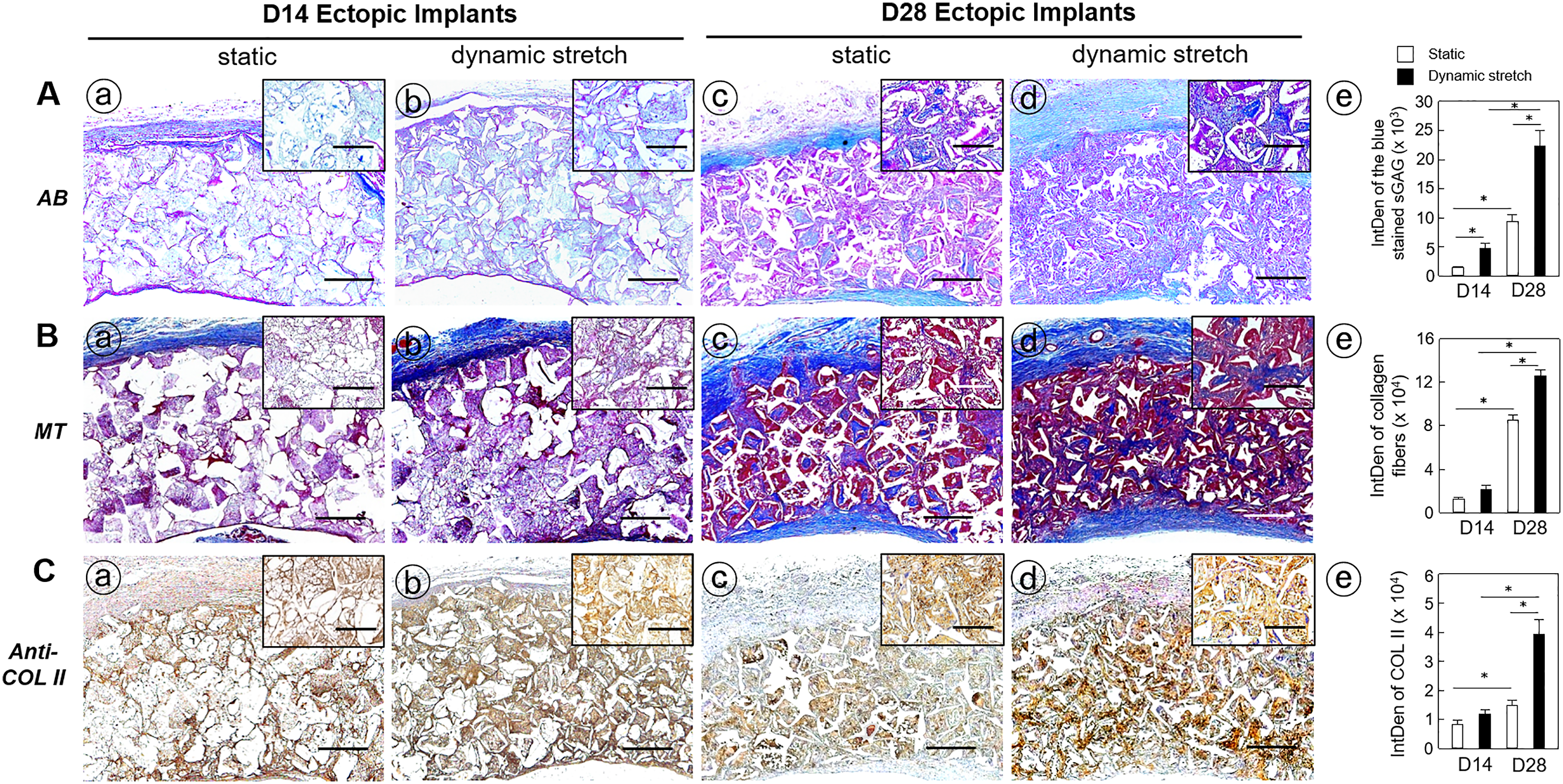
To study the effects of connective and fibrous tissues on the ectopic implants, an implant with and without a silicone tubing in process of ectopically muscular remodeling. Ectopic explants were imaged with the micro-CT, serial sectional images of the explant were observed that an obvious narrowing and luminal stenosis was developed in the ectopic explants without a silicone tubing (Figure S5(A)). However, a clear lumen of explants appeared in the silicone tubed implants (Figure S5(B)).
Histological evaluations of the reconstructed trachea explants
Stronger staining of cartilage-related sGAG macromolecules with Safranin O in the reconstructed trachea explants of the dynamic stretch group (Figure 7(Ab, c)) compared with of static group (Figure 7(Aa)). In addition, enhanced staining of collagen fibers of the invasive fibrous tissues with Masson’s trichrome in the reconstructed trachea explants of the static group (Figure 7(Ba)) compared to dynamic stretch group (Figure 7(Bb, c)). An increased IHC staining of COL II macromolecular protein with anti-COL II antibody in the reconstructed trachea explants of the dynamic stretch group (Figure 7(Cb, c)) compared with of static group (Figure 7(Ca)). Moreover, the formation of micro-vessels in the reconstructed trachea explants was immuno-stained with anti-CD31, a marker of the vascular endothelial cells. A higher presence of the CD31+ endothelial cells in the reconstructed trachea explants of the dynamic stretch group (Figure 7(Db, c)) compared with of static group (Figure 7(Da)). Furthermore, re-epithelization in the reconstructed trachea explants was noted. The pseudostratified native tracheal epithelium (Figure S6(A)) was thickened and migrated to the trachea-TET implant anastomotic region (Figure S6(B)). The mature epithelium (5-6 cell layers thick) migrated to the implanted TET (Figure S6(C)) and the immature epithelium (2-3 cell layers thick) migrated to the anastomotic region between two tandem pedicled TET implants (Figure S6(D)). In fact, the implanted TET itself without the epithelium layer, which re-epithelized by the migration of the native epithelial cells towards the tandem pedicled TET implants from two ends of the native trachea. Histological and IHC analysis of the reconstructed tracheal explants. The reconstructed trachea explants were stained with Safranin O (A), Masson’s trichrome (B), anti-COL II (C), and anti-CD31 (D). The reconstructed trachea explants of the static group (a) and dynamic stretch group (b) were assayed. Scale bar (500 μm) in each picture was obtained under the 10x magnification objective. The insert was captured in a high-power (40×) magnification. Scale bar (50 μm) in the inserts. The integrated density of each staining was analyzed with ImageJ (c). Values represent mean ± SD (n = 4–6). *p < 0.05. SO, safranin O staining; MT, Masson’s trichrome staining; anti-COL II, anti-type 2 collagen IHC staining; anti-CD31, anti-CD31 IHC staining; IntDen, Integrated density.IHC: Immunohistochemistry staining.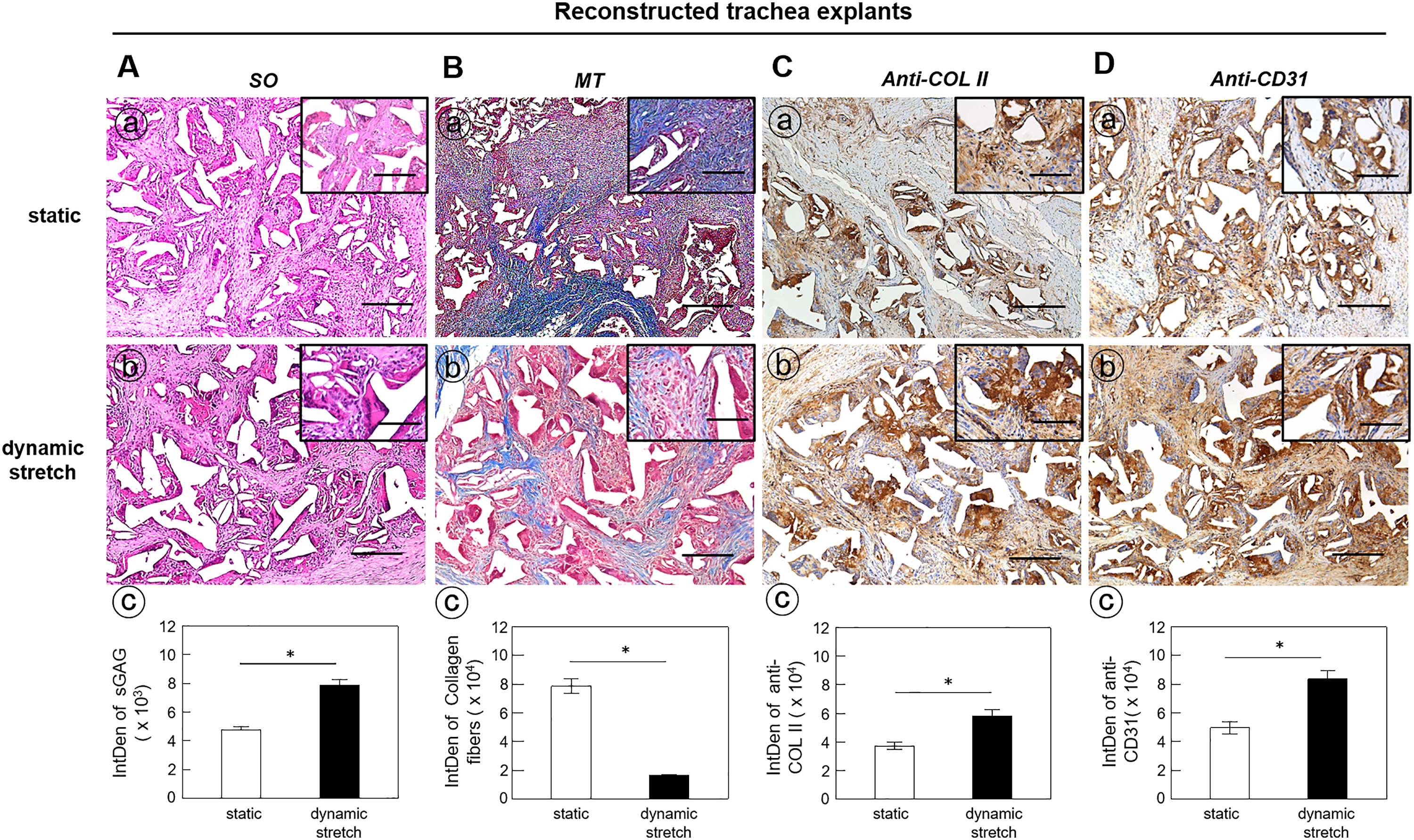
Under physiological conditions, the extracellular matrix protects chondrocytes from contact with immune cells and transplanted allogeneic cartilage fragments are not rejected. However, cartilage produced by allogeneic chondrocytes elicits an immune response from the recipient and is gradually destroyed. 48 Immune response of allogeneic chondrocytes is induced by contact of cellular membrane molecules with immune cells. Generally, chondrocytes constitutively express class I MHC. Expression of MHC class II molecules is induced in vitro by pro-inflammatory cytokines and in vivo in the course of the rejection of transplanted allogeneic cartilage. As illustrated in Supplementary Figure S7, high level expression of MHC class I molecules in the tracheal explants composed of allogeneic chondrocytes in the static group (Figure S7(Aa, e)) and dynamic stretch group (Figure S7(Ab, f)), but not the native trachea cartilage tissues (Figure S7 (Ac, g)). Moreover, low expression of MHC class II molecules scattered in the tracheal explants composed of allogeneic chondrocytes in the static group (Figure S7 (Ba, e)) and dynamic stretch group (Figure S7 (Bb, f)), but not the native cartilage tissues in trachea (Figure S7 (Bc, g)). An antibody isotype control was performed by using non-immune IgG (Figure S7(C)).
Discussion
In this study, a unique bioreactor was developed and designed to produce radial stretch of tracheal grafts. Unlike other bioreactors reported previously, the dynamic stretch bioreactor can provide cyclic stimulation specific to the hollow grafts. The working of the dynamic stretch bioreactor actively conducted a radial stretch of the constructs. This is not like the compressive bioreactor. In addition, the hollow construct is a closed-loop for force transmission. Radial stretch increased the circumference of the construct, thereby offering the strain force to the construct in the tensile/stretch cycle. Under the stimulation of dynamic stretch, the expression of chondrogenic genes and sGAG was upregulated. Consistently, it was reported that compressive strain could elevate the synthesis of sGAG and the expression of chondrogenic genes.23,28 In the gene expression analysis, Acan, Sox-9, and Col2a1 genes were up-regulated by dynamic stretch even in a very short-term mechanical stimulation. 49
The fibroblasts can be activated by cytokines, such as TGF-β, 50 platelet-derived growth factor, 51 and VEGF 52 which activate and further recruit fibroblasts. In order to repair the damaged tissues, activated fibroblasts deposited COL I ECM; however, excessive secretion of ECM leads to undesirable fibrosis which invades into the implant and further impairs the function of the implant. 53 In an ongoing study in our group, that chondrocytes and cartilage ECM macromolecules in the TET and reconstructed trachea explants were insufficient to prevent the infiltrative invasion and further replaced the intra-TET neo-cartilage tissues with the exogenous fibrous tissues derived from the pedicled flap in the static group. Moreover, a large amount of COL I derived from infiltrated fibrous tissue was spread all over TET in the static group following ectopic remodeling, less COL I, however, appeared in the TET of the dynamic stretch group (data not shown). It is suggested that construct with dynamic stretch stimulation was much capable of suppressing the invasion of fibrous tissues and further temporarily delay the invasion process of fibrous tissues.
In the current study, cartilage lacunae were not developed, which indicates that cartilage tissue has not yet reached maturity, in the reconstructed trachea explants. It is possible that only primary chondrocytes were employed, rather than co-cultured with bone marrow stem cells, which was recently demonstrated that has a better potency on chondrogenic differentiation in the TET. 49 On the other hand, the incubation chamber of dynamic stretch bioreactor preliminary designed in sealing closed environment was generally assumed to form a hypoxic culture condition, which is unsuitable for cell survival and growth, and even induction of cell death. However, the evidence demonstrated that an elevation of chondrogenesis-related genes and accumulation of matrix macromolecules via the hypoxia-inducible factor 1-alpha-dependent signaling triggered by the hypoxic culture environment.50,52 Therefore, only chondrocytes were used in the current study rather than the co-culture model. In fact, the culture medium used static and dynamic stretch groups in the sealed incubation chamber was refreshed once 2 days, and the pH values of the cultured medium in either static or dynamic group were in the range of 7.35–6.92, suggesting that is a stable environment for chondrogenic induction even in a sealing closed chamber.
It has been proved that convective mixing (e.g., in spinner flask bioreactors) and convective flow (e.g., in perfusion bioreactors) can improve initial cell seeding density and homogeneity, thereby improving tissue architecture.17,31 These bioreactors can function as a device for cell loading. With micro-CT and histological analysis, the chondrocytes were infiltrated into the central region of the construct after the stimulation of dynamic stretch. The dynamic stretch bioreactor is designed as a mechanical stimulator for tube-like 3D hollow grafts such as tracheal and vascular grafts. Meanwhile, the porous structure of the PCL scaffold under a cyclic radial stretch could promote the exchange of gas, nutrients, wasted metabolites, and even benefit cell infiltration into scaffolds. The scaffolds produced with the salt leaching method were expected to create space for cell adhesion, aggregation, and growth. However, some closed compartments were found, thereby limiting cell immigration and resulting in a non-homogenous distribution of cells. Interestingly, the dynamic stretch bioreactor played a role in increasing the deposition and accumulation of the cartilage-specific extracellular matrix macromolecules via various mechanisms such as the increase of micropore formation which assisted cell infiltration. Alternatively, it is possible that dynamic mechanical stimulation influenced solute transport within the scaffold that, in turn, influenced cell migration into the scaffold. 31
For more than 50 years, several approaches have pursued to reconstruct the airways when conventional surgical approaches were unsuitable.6,32 However, the resulting preclinical outcome was inconsistent, incomplete, and controversial. Most of the evaluated tissue engineering strategies resulted in being suitable only as patches for small airway repairs and were unable to resist collapse when used for whole long-segment airway applications. In the clinic, patients with large segmental tracheal lesions commonly require a permanent tracheostomy after tumor excision. 1 Thus, a long-segment TET with appropriate stiffness is the final goal of studies in trachea tissue engineering. As described above, our dynamic stretch bioreactor can stimulate multiple constructs at the same time. The constructs were thought of as the building blocks which can be flexibly arranged in the stage of the ectopic incubation in a muscle flap. In order to be satisfied with repairing a long-segmental defect, a long segmental tracheal TET graft could be made with a tandem composition of several tissue-engineered constructs. In the current study, the pre-vascularized TET implant was prepared with two tandem arranged constructs in the process of the ectopically intramuscular incubation. Furthermore, the dynamic stretch bioreactor can stimulate a long-segment cylindrical construct, and help the cell infiltrated in the scaffold. There are only a few strategies and technologies available for evaluating the function and stability of the cylindrical construct. The dynamic stretch bioreactor can test the stability for a long period or perform the fatigue test by raising the working frequency. Different materials can be screened and tested by this dynamic stretch bioreactor; thus, it provides a new approach to improve the development of implants in tracheal tissue engineering.
Conclusion
In vitro stimulation with dynamic stretch increased the infiltration of cells into scaffolds, accelerated the formation of neo-cartilage, the beneficial effects of mechanical stimulation of dynamic stretch in vitro were long-lasting on the ectopically implanted TET and reconstructed trachea. This novel dynamic stretch bioreactor device can be used to process a long-segment TET in a clinic or to examine the materials and scaffolds in a laboratory.
Supplemental Material
Footnotes
Declaration of conflicting interests
The author(s) declared no potential conflicts of interest with respect to the research, authorship, and/or publication of this article.
Funding
The author(s) disclosed receipt of the following financial support for the research, authorship, and/or publication of this article: This work was supported by the Chang Gung Memorial Hospital (grand numbers CMRPG3E0081, CRRPG3E0192, and CRRPG3E0193).
Ethical approval
This study was approved by the ethics committee of the Ethics Committee of Chang Gung Memorial Hospital.
Supplemental Material
Supplemental material for this article is available online.
References
Supplementary Material
Please find the following supplemental material available below.
For Open Access articles published under a Creative Commons License, all supplemental material carries the same license as the article it is associated with.
For non-Open Access articles published, all supplemental material carries a non-exclusive license, and permission requests for re-use of supplemental material or any part of supplemental material shall be sent directly to the copyright owner as specified in the copyright notice associated with the article.