






Abstract
Sealing glasses are advantageous materials for joining of metals, ceramics or other glasses. For many applications, the sealed composite has to withstand high temperatures. Above the softening temperature of the glass, simple sealing glasses can usually not be used and crystallizing sealing glasses are required.
The most important properties of the crystallized sealing glass are good adherence to the material to be sealed and a good match of their coefficients of thermal expansion (CTE). The chemical composition of a glass seal can be varied in a wide range and hence also its physical properties. For the joining process, glass powder is given in between the materials to be joined. During subsequent heating, sintering of the glass by viscous flow and finally nucleation and crystal growth takes place. The supplied temperature/time schedule should be designed in such a manner that densification occurs before a notable quantity of crystal phase is formed. The formed crystalline phases and their CTEs are decisive for the CTE of the crystallized seal, because a mismatch in the CTEs results in stresses during cooling. For non-cubic crystalline phases, also the anisotropy of the CTEs is of high importance, because it leads to internal stresses within the crystallized seal. A high degree of anisotropy should hence be avoided.
The chemical composition of the crystallizing glass seal has to be tailored in such a manner that the type and quantity of the respective crystallized phases as well as the composition of the residual glass phase result in the aimed CTE as well as in good adherence to the materials to be joined. During application, both CTE and adherence should not change notably with time. Hence, during application at high temperature, further crystallization should not take place and type and volume concentration of the crystalline phase should remain constant.
Introduction
Glass seals are advantageous materials to join various materials, such as ceramics, metals or other glassy materials.1–4 The chemical compositions of glass seals are highly variable and hence, the physical properties can also be varied in a wide range. For the joining process, powdered glass is used and given in between the materials to be joined, frequently after plasticising with organic additives.2,5 During subsequent heating, first organics are burnt out and then after exceeding the glass softening temperature, sintering by viscous flow occurs until a gas-tight joint is achieved. During subsequent cooling, stresses due to a mismatch in the coefficient of thermal expansion (CTE) may form below the glass transition temperature (Tg). 6
Depending on the respective application, the compound has to withstand high temperatures. That means, if the application temperature is equal or above the softening temperature, simple glass seals cannot be used. In those cases, subsequent to the sintering process, the glass has to be crystallized, so that a glass-ceramic seal is formed.1,2,4,5 This is usually done by an appropriate thermal treatment. Even if the softening temperature of a residual glass phase is below the application temperature, the seal will be mechanically stable in many cases. However, this strongly depends on the microstructure and the volume concentration of the residual amorphous phase.
During crystallization of the sealing glass, the coefficient of thermal expansion changes and is governed by the CTEs of the formed crystalline phase(s) and the glass phase, which now has another chemical composition. One major problem is the long-time stability of the crystallized layer. For example, if during application at high temperature, further crystallization takes place and the volume concentration of the crystalline phase increases, or, if another crystalline phase is formed during long time exposure at high temperatures, the CTE may change with time. This might lead to supercritical stresses while changing the temperatures, which results in cracks and finally in a failure of the composite.
Another problem is the adherence of the seal to the materials to be joined. Usually, both ceramics and metals are well wetted by a glass melt. However, during crystallization, the adherence may notably change. One strategy to overcome this problem especially in the case of the adherence of metals to the seal is the use of reactive seals7,8 as described in detail in chapter 8.
The chemical composition of crystallizing glass seals has to be tailored with respect to the material to be joined and the respective application temperature. One of the target values is the CTE of the seal after crystallization (which should not change to a large extend during the application). Furthermore, a strong adherence to the materials to be joined must be given during the whole intended lifetime of the composite.
As alternative approach, a powdered glass can be mixed with a crystalline phase of known CTE and then sintered without further crystallization.9,10 This approach is denoted as “composite glass seal” and was sometimes used to achieve a certain CTE of the seal. It is especially used, when the CTE of the glass should be lowered by the addition of ceramic additives with very low or negative thermal expansion. The disadvantage of this approach is the more difficult sintering, because viscous flow must occur around the crystalline particles. Furthermore, a dissolution of the crystalline particles during sintering as well as crystallization during sintering or at the application temperature have to be taken into account.
This review is focused on silicate glasses as crystallizing glass seals. Composite glass seals are not further considered.
Application of glass seals
Applications for glass seals are quite numerous and hence, only an overview can be given. Details are known only for very few systems.
Non-crystallized systems
Non-crystallized sealing glasses are commercially available for many purposes usually as powdered glass.11–13 The glass powder is given between the materials to be joined. During subsequent thermal treatment, the glass is sintered and the materials to be joined are wetted by the molten glass. 14 After cooling and during application, the seal is still glassy and is not crystallized and hence does not change its physical properties. Non-crystallizing sealing glasses are available for a wide range of CTE required for specific applications.13,14 Besides the CTE, the required physical properties are sufficient corrosion resistance under the application conditions and sufficiently good mechanical properties for the respective purpose. For applications in electrical engineering also the electric properties, such as specific electric resistivity, dielectric constant and loss angle are of importance.
Glass seals which are not crystallized, do not reach the mechanical stability of crystallizing glass seals. If the application temperature is somewhat above Tg of the sealing glass, viscous flow may take place which affects the geometry of the composite. Otherwise, unintended crystallization may occur which changes the CTE of the seal and other physical properties in a not acceptable extend. For applications at room temperature, non-crystallizing glass seals are nevertheless the first choice, if the materials to be joined do not possess CTEs < 3·10−6 K−1.
Crystallized systems
In contrast to non-crystallized glass seals, crystallized systems are especially designed for applications at high temperatures. After sintering of the glasses and wetting of the materials to be joined, during subsequent thermal treatment, the glass is crystallized. This changes the physical properties in a large extend. Then the CTE of the seal depends predominantly on the CTEs of the crystallized phases and their volume concentration, but is also affected by a residual glass phase.
In the scientific literature, the most frequently reported application of crystallizing glass seals is dedicated to Solid Oxide Fuel Cells, SOFC (see, e.g.,15,16). SOFCs are considered as key components for hydrogen technology.17–21 Nowadays, most SOFCs have a planar design and a seal between an ion conductive ceramic component, mostly yttrium stabilised ZrO2 as electrolyte and a metallic component (steel or Ni-alloy) as electron conductor are required.17,18,20–22 The seal should be gastight and electrically insulating and stable also with respect to O2 and H2 at the respective application temperature which lies in between 800 to 950 °C. Furthermore, the composite must withstand thermal cycling from room temperature to the application temperature.
The materials to be joined, stabilised zirconia and the metallic component have comparatively high CTEs. The most frequently applied metal is Crofer 22 APU™ with a CTE of 11.5·10−6 K−110 while tetragonal yttrium stabilised zirconia, YSZ, (space group: P42/nmc (137)) has a CTE of 10.4 and 14.8·10−6 K−1 for the crystallographic a- and c-axis respectively which is equivalent to a mean CTE of 11.9·10−6 K−1.
23
According to Ref.,
24
the cubic yttrium stabilised zirconia (space group Fm
Another important field of application are high temperature reactors, which are operating at even higher temperatures than SOFCs, i.e., at 1000 °C and even above. This requires the use of nickel alloys such as NiCrofer™, which possesses higher CTEs than Crofer™ steels. 28 An example is a high temperature reactor composed of a NiCrofer™ alloy and hollow fibres of perovskites which show O2− ion conductivity as well as electron conductivity. At high temperatures, air flows through the fibres under high pressure and oxygen permeates as O2− ions through the walls of the hollow fibre and at the same time electrons permeate in the opposite direction, i.e., the hollow fibres are permeable for oxygen, but not for nitrogen, argon and other gases. This technology might replace the Linde process for air separation in the future 35 and might also enable economically more advantageous oxyfuel technologies as well as carbon recovery.
A standard application for crystallizing glass seals is joining Al2O3 ceramics to other Al2O3 or single crystalline sapphire components, also for applications at high temperatures. Corundum has a space group of R
There are numerous applications where metals are joined to ceramics or other metals of high CTEs, many of them at room temperature for electronic applications. Since numerous metals, such as copper (16.5·10−6K−1), iron (11.8·10−6K−1), molybdenum (4.8·10−6K−1), nickel (13.4·10−6K−1) 38 and various steels are of importance, which have quite different CTEs, besides some standard crystallizing glass seals, also various seals with compositions tailored to the respective metal and the respective application are required.
Other applications of crystallized glasses
Other applications of crystallized glasses are first of all glass-ceramics. The most frequently industrially produced glass-ceramics possess a CTE close to zero, i.e., they do not expand during heating. The main applications of such glass-ceramics are high temperature (furnace) windows, cook top panels and telescope mirrors and39–42 as well as numerous devices for applications in optics and photonics. The CTE close to zero is required for telescope mirrors blanks and photonic applications to minimise shape changes with temperature and for cook top panels and furnace windows to achieve a high resistance against thermal shock.
Another important application is that of dental materials. Here, besides mechanical properties and the CTE, also optical properties such as a certain translucency are required for aesthetic reasons. There are very different materials available for various purposes, such as veneers, inlays, dental crowns or bridges. 43
Glass-ceramics may also have interesting mechanical properties, such as high hardness (up to 14 GPa 44 ), high Young's modulus (>140 GPa 45 ), high mechanical strength (>1 GPa46,47) and high toughness (>4 MPa·m1/2). 48 Applications are, e.g., found as armour materials.
Another field of interest are machinable glass-ceramics. They contain, e.g., mica crystals, which have cleavage planes and enable comparatively rapid machining by conventional hard metal tools. Such materials find, e.g., applications in rapid prototyping. 49
Additional applications for glass-ceramics are found in a wide range of electronic devices, such as piezoelectric50,51 or dielectric52,53 components. Here, especially surface crystallized polar glass-ceramics based on fresnoite are to be mentioned. 53
Glass crystallization is also of importance, if crystalline ceramic powders are sintered using a glass phase as sintering aid. Then, it might be favourable to crystallize the glass phase after sintering is complete. This has two advantages: the first is that the mechanical properties should improve because mechanical strength and toughness of the crystalline phase should be better than of an amorphous phase. The second is that the high temperature performance should be better, because softening of a glassy phase does not occur.
CTEs and stresses formed in the sealed composites
Stresses between the layers
The stresses in the seal and the joined materials are formed during cooling and are due to the CTEs as well as to possible phase transitions. With respect to the CTEs, the mismatch of the mean CTEs of the seal and the respective joined materials leads to an overall stress between these materials. For a simple geometry (planar layers), stresses formed at the boundaries between two materials with different CTEs, can be calculated using equation (1).
54

With σ: formed stress, CTEA, CTEB and EA, EB: coefficients of thermal expansion and Young's moduli of the materials with the indices “A” and “B”, respectively. Tmin is the minimum temperature, at which mechanical stress relaxation by viscous flow of the glass phase is possible. For a comparatively high concentration of residual glass phase, Tmin is equal to the glass transition temperature, Tg. If the CTE of material A is larger than that of material B, σ is, according to equation (1), positive, which means that the stresses in material A are tensile, while they are compressive in material B.
In a further approximation, Tg depends on the cooling rate according to Bartenew Equation
55
and decreases with decreasing cooling rate:

With q = cooling rate, Eq = activation energy of viscous flow, R = Avogadro's constant. A is a constant depending on the chemical composition.
The stresses between two materials with different CTEs are high, if Tg of the glass is high, the Young's moduli are high and the difference in the CTEs of both materials is large. For more complex geometries, finite element calculations, FEM, are necessary. Figure 1 shows a schematic of a three-layered material composed of a material B with the smallest CTE and a material A with the highest CTE, while the CTE of the glass seal lies in between. In the material A, tensile stresses and in the material B only compressive stresses occur. In the seal, in contact to material A, the stresses are compressive while they are tensile in contact with material B.
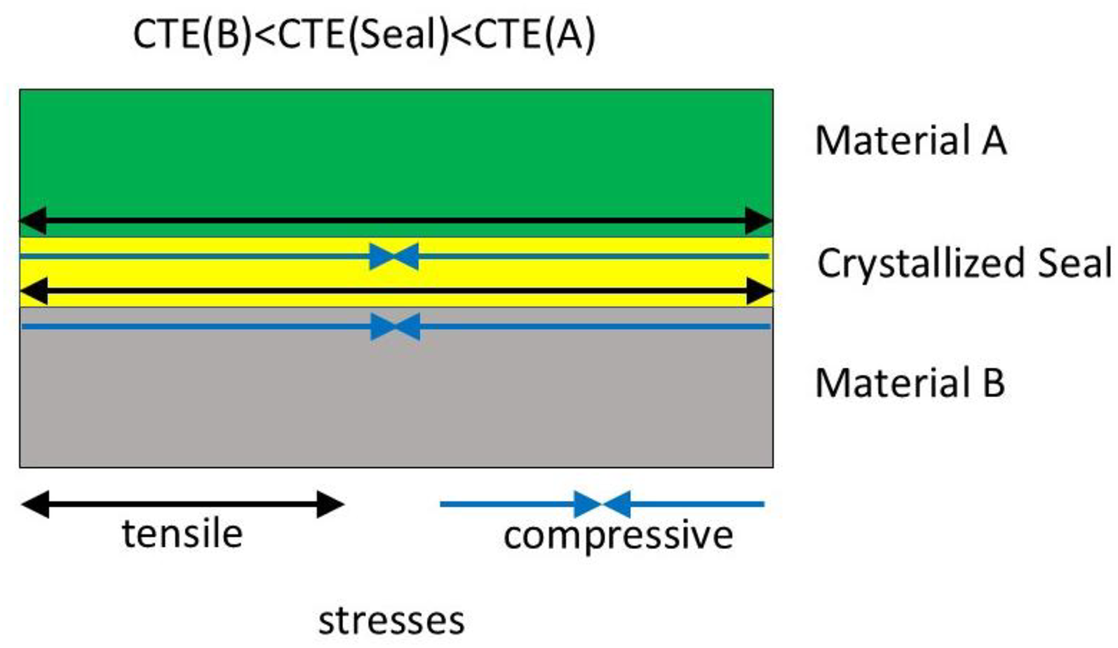
Stresses formed in layers composed of a material A, a glass seal and a material B for the case, the CTE of material B is smallest and that of material A largest, while that of the seal lies in between.
Stresses within the crystallized seal
In addition to the stresses between the layers, internal stresses in the crystallized seal occur, which are attributed to the mismatch in the CTEs of different crystalline phases with each other and also with the residual glass phase. In the case of crystalline phases which do not possess a cubic space group, the CTEs are different in different crystallographic directions which also notably affects the internal stresses. These internal stresses strongly depend on the respective microstructure and can only be calculated for simple geometries, such as low concentrations of spherical isotropic crystals in an amorphous matrix. The stresses around a spherical and a needle-shaped inclusion, which are stress-free at high temperature and which are afterwards cooled down to room temperature are shown in Figure 2(a). The stresses in a spherical inclusion are isostatic and if the CTE of the inclusion is larger than that of the matrix, are tensile. In the matrix, the stresses in axial direction are also tensile, while they are compressive in radial direction. 54
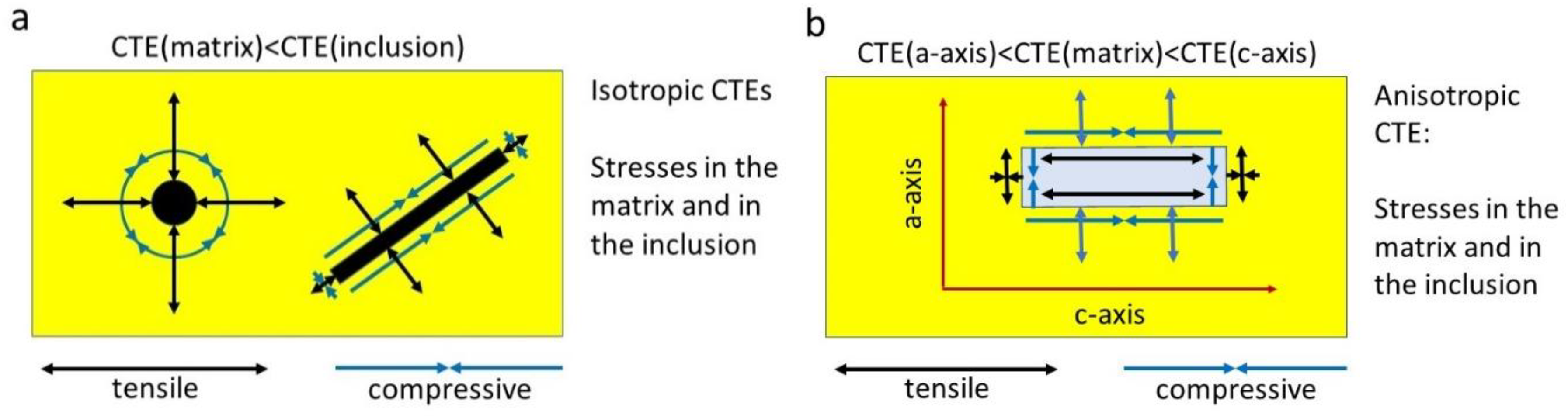
Stresses around inclusions a: stresses around a spherical inclusion and a needle-shaped inclusion for the case, the CTE of the matrix is smaller than that of the inclusion. b: stresses around a needle-shaped tetragonal inclusion which CTE in the direction of the crystallographic c-axis is larger than the CTE of the a-axis, while the CTE of the matrix lies in between.
For a spherical inclusion, stresses can be calculated from the CTEs, the Young's moduli and the Poisson ratios according to Selsing.
54
It should be noted that this equation is only valid for inclusions in an infinitely large matrix and for a realistic microstructure can only be a first approximation.
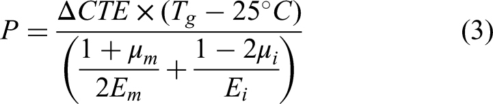
With: P = stress inside the inclusion, Em and Ei = Young's moduli, and μm and μi: Poisson's ratios. Index m = matrix and i = inclusion. ΔCTE = CTEm − CTEi. The equation is valid for room temperature (25 °C) and Tg is in °C and for small concentrations of the crystalline phase. For higher concentrations (f = volume concentration of the inclusion), another equation was proposed by Hsueh and Becher
56
(see also
57
):

With: K and G are the compressive modulus and the shear modulus, respectively. The indices, “m” and “i” are again for the matrix and the inclusion, respectively.
The stresses in the inclusion do not depend on its size. In the matrix, tangential stresses (σt) and the radial stresses (σr) decrease with R3/d3 (with: d = distance from the centre of the particle and R = radius of the inclusion) as described by equation (5)
54
:

Please note that the signs for the radial and tangential stresses always oppose each other.
In a needle shaped tetragonal inclusion with a CTE larger than that of the matrix, the stresses inside the inclusion are tensile (see Figure 2(a)). In the direction pointing away from the crystal, the stresses are also tensile, while they are compressive parallel to the surface of the crystal. The stresses inside the crystal are not isostatic, but depend on the locus, even if the CTEs in different crystallographic directions are the same. That is generally valid for non-spherical inclusions.
A somewhat more complicated stress field occurs in a needle shaped crystal with anisotropic thermal expansion, e.g., which CTE is larger in the direction of the crystallographic c-axis than in the direction of the a-axis, while the CTE of the glass matrix lies in between. Inside the crystal (see Figure 2(b)), parallel to the c-axis, tensile stresses occur, while the stresses are compressive perpendicular to the c-axis. In the matrix compressive stresses occur along the c-axis as well as in radial direction. Parallel to the (001)-plane, tensile stresses occur and also perpendicular to this direction.
An even greater effect on the formation of stresses may have transitions from one crystalline phase to another one below Tg, which are accompanied by a volume effect. Such crystalline phases are, e.g., β-quartz, which transforms to α-quartz58,59 or the β-cristobalite/α-cristobalite59,60 transition both occurring during heating and cooling. It should be noted that this volume effect is not isotropic, i.e., the relative changes in the axes of the unit cell are not the same and hence also in the case of phase transitions, around and in the crystals tensile and compressive stresses are formed.
FEM enables the calculation of stresses in more complex microstructures. Elaborated microstructures, such as high concentrations of different crystalline anisotropic phases with statistic orientations in a comparatively low concentration of glass phase up to now cannot be calculated properly. It should be noted that during crystallization also the composition of the glass melt changes and hence diffusion gradients are formed which leads to a local dependence on the CTE of the glass.
Another effect, which leads to local stresses and anisotropic CTEs is the orientation of crystals as a result of nucleation and crystallization. Nucleation of the sintered glass may happen in a different manner as in the case of an as cast bulk glass. The first is homogeneous nucleation in the glass, while the second is nucleation in residual pores caused by incomplete sintering or by nucleation during earlier states of sintering. In these two possibilities, the arrangement of the crystals with respect to their orientation should solely be statistic. If, however, nucleation takes place at the interface of the material to be joined and the sintered glass, the formed nuclei have already a preferred orientation in many cases. 61 Also in the case, the nuclei are not oriented, during the growth of crystals with non-cubic space groups and different crystal growth velocities in different crystallographic directions, the crystals are in many cases oriented in some distance (few μm) from the locus of nucleation. 61 Since these non-cubic crystals usually exhibit different CTEs in different crystallographic directions, this orientation may have a serious effect on the CTE. Hence, the CTE of a crystallized glass seal parallel to the materials to be joined is not necessarily the same as in a material the crystals are statistically oriented.
Effect of time on stresses during application
In principle, two types of applications of crystallizing glass seals can be distinguished: In the first type, the application temperature is the room temperature (±60 K). At room temperature, the crystals cannot grow and only in very rare cases can show phase transitions. An example for the latter case is the stress induced transition of tetragonal ZrO2 to monoclinic ZrO2. Hence, usually at room temperature, the phase composition does not change with time and hence also not the CTE. Thus, also the stresses are constant with time.
The second type are high temperature applications. Here, type and volume concentration of crystalline phase(s) as well as the microstructure may change during the application. Besides, chemical reactions between the seal and the joined materials may occur. In such applications, in many cases, thermal cycling occurs, i.e., the composite is heated up and cooled again many times.
At high temperatures, the type, quantity, and shape of the crystalline phases may be affected, i.e., may change as a function of time. For example, the crystallization of the glass phase may proceed. Here two cases can be distinguished: the first is the crystallization in an isochemical system. The crystals grow and the composition of the residual glass phase remains constant (see Figure 3(a)). During the course of the crystallization, the CTE approaches the CTE of the crystalline phase. In non-isochemical systems, diffusion gradients form around the crystals (Figure 3(c)), further phases might crystallize (Figure 3(b)) or Ostwald ripening (Figure 3(d)) takes place. Another possibility is that the shape of the crystals changes and approaches the thermodynamically most advantageous morphology (Wulff shape) 62 attributed to a minimum of the interfacial energy (see Figure 3(e)). For example, initially a crystal may grow in needle-like morphology for kinetic reasons, e.g., along a screw axis. After some time, the crystal, however, may minimise its interfacial energy and the length will decrease again, while the crystal gets thicker. 63 Such behaviour was denoted as “crystallization pendulum” (Figure 3(e)).
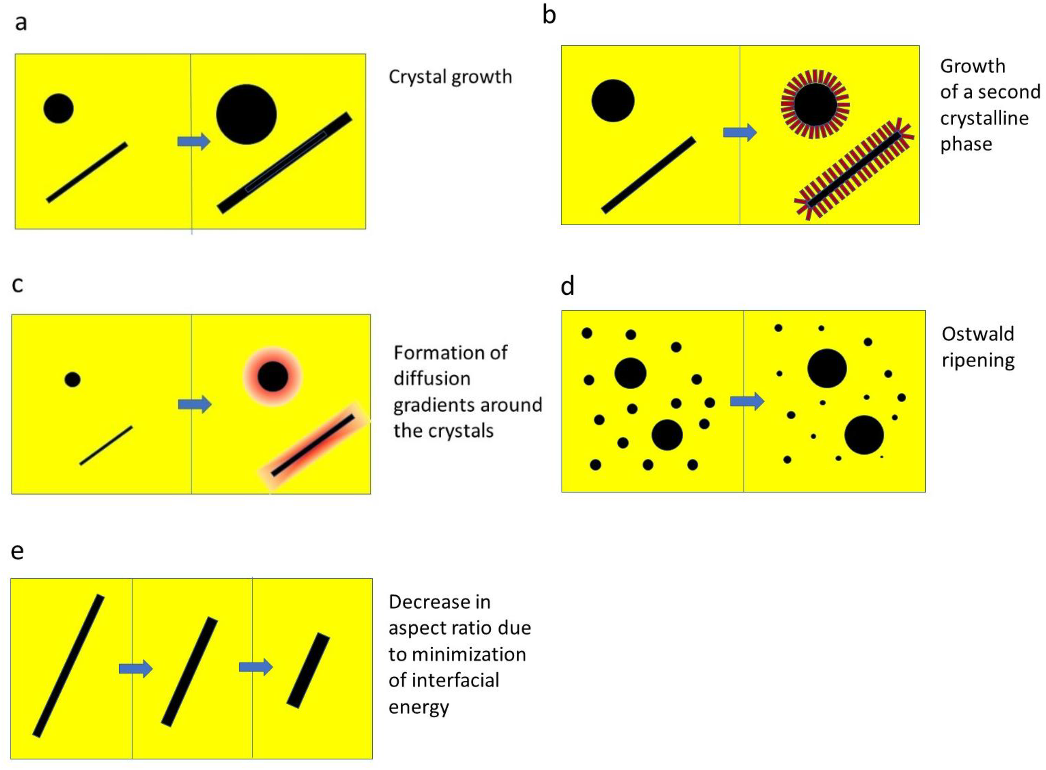
Possible effects during high temperature treatment: a: crystal growth in isochemical systems of spherical particles and of needle like particles (possibly along screw dislocations). b: epitaxial growth of a second crystalline phase, c: formation of diffusion gradients around the crystals in non-isochemical systems, d: Ostwald ripening to minimise the interfacial energy, e: Decrease in aspect ratio to minimise the interfacial energy.
Furthermore, also the internal stresses caused by mismatches in the CTEs combined with changes in the phase composition (including phase transitions during cooling), the microstructure (e.g., also the aspect ratio of the crystals) and the composition of the glass phase are affected.
Sintering of glass
Sintering of glass without crystallization
Sintering of glass is achieved by viscous flow. A requirement is hence, that at the temperature, the glass is sintered, crystallization is negligible and does not notably hinder the densification process, i.e., the volume concentration of crystals is still low. Since the glass used for this purpose is usually made by melting and subsequently powdered by milling, the particles are polydisperse and have a certain particle size distribution. Furthermore, particles prepared by milling are not spherical. The shape, size and size distribution of the particles are decisive for the densification process. With decreasing particle size, the driving force for sintering (minimisation of surface energy) increases.
Figure 4 shows a schematic for densification of two amorphous spheres by viscous flow in an initial state of sintering. The spheres have a radius R, which is somewhat larger than the initial radius R0. The radius R is much larger than the curvature r. 64 Hence, the latter leads to a transport of material to the neck by viscous flow, according to Frenkel's theory, 65 later further developed by G. Kuczynski66,67 and J. Mackenzie and R. Shuttleworth 68 as well as by I. B. Cutler.69,70
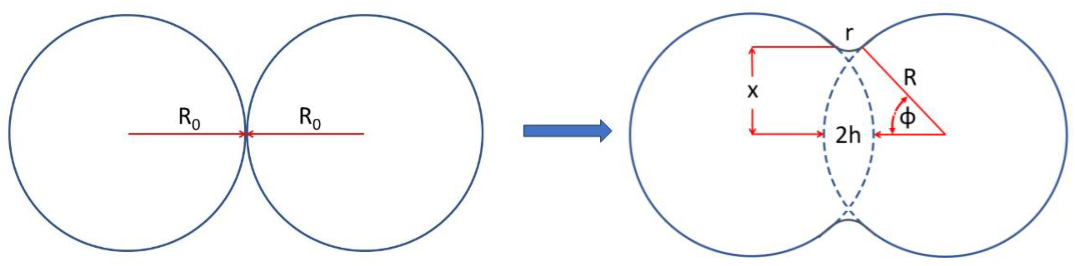
Two amorphous spheres with the radius R in an initial stage of sintering by viscous flow. Redrawn after Ref. 64
According to,
64
the rate of initial neck growth is given by equation (6):

With γ = surface tension, η(T) = temperature dependent viscosity, t = time, x, r and R: see Figure 4.
The (macroscopic) volume shrinkage ΔV of particles with the radius R is given by equation (7):

With ΔL = linear shrinkage. A full coalescence of the glass spheres with the initial radius R0 is reached after a time τ:

With x ≈ R0 and h = R(1-cosφ), h and φ: see Figure 4. If an initially dense package of glass spheres is assumed, a large specimen with closed pores forms with the densification rate according to equation (9):

With n = number of pores per volume unit, ρ’ = relative density and t0 is the time the experiment was started. The term γn1/3(t-t0)/η is denoted as reduced time. The relative density as a function of the reduced time is shown in Figure 5.
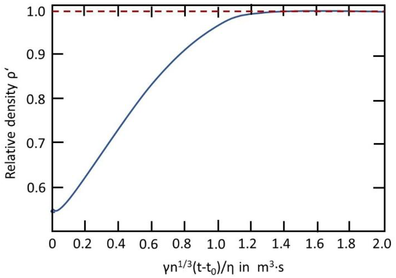
Reduced density of a compact composed by glass spheres of unit size plotted against the reduced time for a constant temperature. Redrawn after. 64
The relative density at the beginning is around 0.55 (the typical value, a powder can be densified by pressing) and during thermal treatment at a constant temperature approaches with time a value of 1, which is equivalent to a full densification. It should be noted that in a good approximation, the surface energy does not depend on temperature, while the viscosity decreases with increasing temperature according to Vogel-Fulcher-Tammann equation, η = A·exp(B/(T−T0)) with A, B and T0: constants. Hence, the time required for densification is proportional to the viscosity at the respective temperature during isothermal treatment. The curve displayed in Figure 5 is a master curve which in principle applies for all viscosities, i.e., all temperatures.
Sintering of glass with concurrent crystallization
The curve shown in Figure 5 does not take into account a superimposed crystallization process, which depends on the respective supplied temperature/time schedule. A more detailed description of the densification process is given in the following papers, where theoretical work taking into account the concurrent crystallization process was published by M. O. Prado and E. D. Zanotto71–73 as well as by T. E. Clark and S. S. Reed. 74
In principle, concurrent crystallization hinders the densification process of the glass. Nucleation as a first step of the crystallization process might take place in the bulk or, however, at the surface of the glass particles. The maximum nucleation rate is usually observed at temperatures around Tg, whereas the maximum crystal growth velocity is observed at much higher temperature.75,76 As long as the nuclei do not grow much, they do not affect the densification process drastically. Especially, if simultaneously surface crystallization at the particles’ surface takes place, the volume concentration of crystals increases and the densification process gets more difficult. That means, in contrast to solid state sintering of crystalline powders, sintering of crystallizing glass seals is not always facilitated by smaller particle sizes.
Theoretical descriptions of glass sintering with concurrent crystallization suffer from the fact, that the glass powder used in experiments is not composed of spherical particles which all have the same size and hence are only a first approximation.
For an isothermal sintering process, the time until the maximum sintering rate, ts, is reached is given by equation (10)
71
:

With: ρ0 = relative initial green density, r = initial radius of the glass particle. The particles are assumed to possess all a spherical shape and the same size. The factor 1.7 in equation (10) results for ρ0 = 0.6 (a common value for the relative green density) and ρ’ = 0.8 (an estimate for the relative density at the maximum sintering rate).
For an isothermal sintering process with concurrent crystallization, the time until the maximum crystallization rate at the temperature T is reached, tc, is given by equation (11).
71

With: Ns = density of the nucleation sites at the surface of the glass particles, U(T) = crystal growth velocity at the temperature T.
The time until the maximum sintering rate is reached must be shorter than the time, the maximum crystallization rate is reached. For this purpose, in Ref.,
71
a sinterability parameter S was defined:

It was empirically shown in Ref., 71 that the parameter S should be >50 to achieve a relative density >0.99 for glass forming systems, which should be sufficiently high for most sealing purposes.
Equation (12) shows that the densification of crystallizing glasses can be facilitated by (i): smaller particles (r) and lower number of nucleation sites (Ns) at the surface of the glass particles. The latter can be decreased by reducing the time, the sample is held at temperatures around Tg, where the nucleation rate is maximum, i.e., by a larger heating rate in this temperature range. U(T) and η(T) solely depend on the glass composition and can only be affected by the temperature.
Furthermore, numerous experimental papers on concurrent sintering and crystallization have been published (see, e.g.,77,78).
Another general problem during sintering of glass with concurrent crystallization is foaming, if closed porosity is reached.79–81 The reason is the formation of volatiles, such as water during crystallization. Nearly all crystals formed during glass crystallization do not incorporate water and hence water (as OH groups) is enriched in the residual glass melt. If now the concentration of water exceeds the solubility, bubbles are formed. This problem can be overcome by the preparation of “dry” glasses, e.g., by bubbling the melt with dry argon and/or by the incorporation of small fluoride concentrations. Fluoride has a similar ionic radius as OH-groups and occupies similar sites in the glass structure. Hence, fluoride “pushes” the water out of the glass structure and hence helps to minimise the water concentration. Both techniques are well-known from the preparation of rare earth doped glasses for fluorescence applications. 82 In the case of alkaline earth containing glasses, especially those, which contain BaO, foaming might also be a result of the release of carbonaceous species that appear at the surface of the respective glass particles.83–85
Optimisation of the sealing technique and the supplied temperature/time schedule might minimise undesirable effects of concurrent crystallization.
The effect of the interface of materials to be sealed and crystallizing glass are discussed in Section 8.
Sealing techniques
Key information on the respective process are the temperature and time required for sealing and the maximum temperature which can be applied for a certain period of time during the sealing process without damaging the materials or systems to be joined. For many processes and many sealing glasses, the sealing temperature is notably above the application temperature. If then the sealing temperature leads to a damage of the materials to be joined, the sealing material should be optimised with respect to lower sealing temperatures.
Sealing techniques depend on the materials to be joined. If these materials withstand high temperatures, simple sealing techniques can be used. Here, the glass powder is first plasticised. Ref. 86 gives an overview on binder compositions. In most cases, at least four different types of compounds are used, denoted as solvent, dispersant, binder and plasticiser. The particular compounds are for example water or alcohol as solvent, triethanol amine as dispersant, polyvinyl alcohol as binder and octyl phthalate as plasticiser. The plasticised powders are printed, spread, painted, or simply pressed and placed on the materials to be joined. An alternative approach is the use of ceramic foils which usually are produced by continuous tape casting and then brought into the proper geometry, e.g., by laser treatment.87,88 The green tape casted foils are then brought in between the materials to be joined. A further step can be a lamination process usually carried out at temperatures in the range from 120 to 250 °C applying uniaxial pressure.
Then, usually a thermal treatment is carried out, in principle in a multiple step process. Figure 6 shows a schematic of the temperature/time schedule. In the first step, the binder, i.e., the organic part is burned out by applying a temperature of at least 500 °C. Another possible technique is to dissolve the binder in an appropriate solvent, which enables to minimise the time necessary to burnout the binder or even to avoid the burn-out step.89–93 Subsequently, the composite is brought to a temperature, viscous flow occurs. The temperature necessary for this process is strongly dependent on the chemical composition of the sealing glass. During this step, the glass sinters and the majority of the pores are eliminated. Then, the temperature is decreased again to a temperature, the nucleation rate is maximum (somewhat above Tg, see Figure 6, left). Subsequently, the temperature is increased again to achieve crystal growth. In many cases, a simplified temperature/time schedule may be applied, where nucleation occurs during densification and sintering (see Figure 6 right). The total time required for an above described joining process is often up to few hours. In most cases a total elimination of pores is not possible and few volume percent of pores remain. Nevertheless, gas-tight sealing can be achieved.
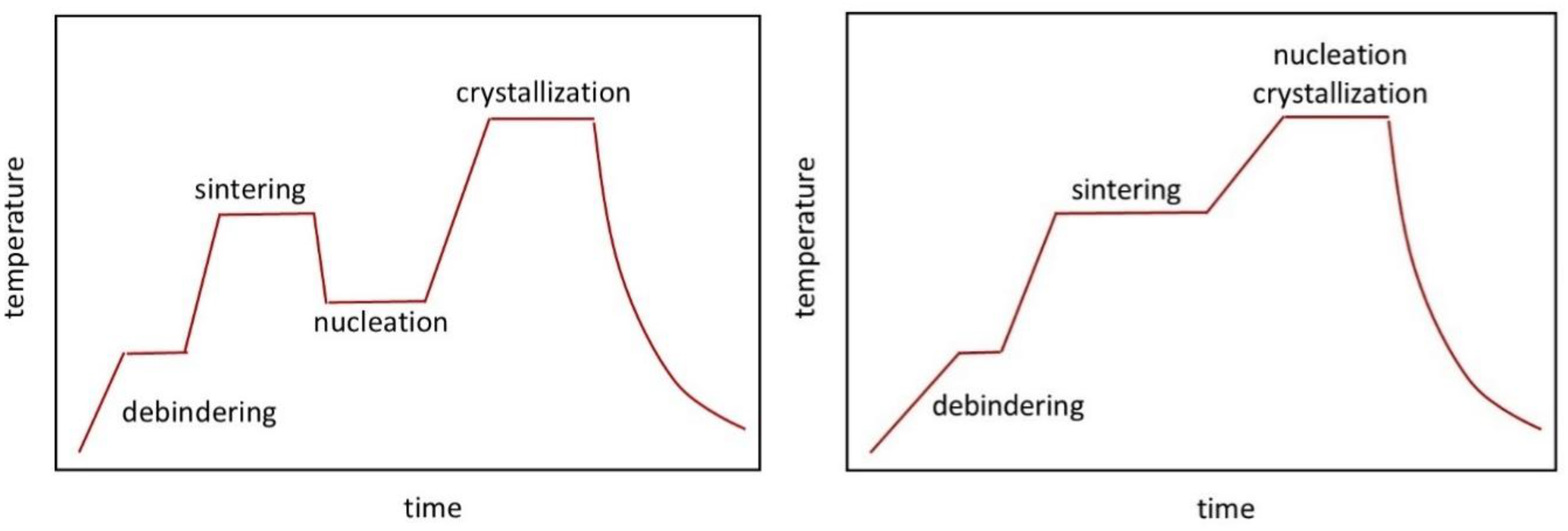
Schematic of the temperature/time schedule of a sealing process. left: nucleation at a separate step, right: nucleation together with sintering and crystallization.
If the materials to be joined are sensitive to the temperature necessary for joining, a more rapid sealing process has to be applied. Here, the most suitable technique is laser sealing. This method enables to apply heat treatment times of few minutes.87,88,94,95 A prerequisite to apply this technique is a controlled and homogeneous heating of the sealing glass in contact with the materials to be joined. At the moment, to the best of our knowledge, this method is mostly applied for comparatively simple geometries, such as tubes or plates.
Another suitable technique is the heating by a flame. This method is also difficult to apply, because the temperature as a function of time is difficult to control. 96
Joining of dissimilar materials, e.g., of a metal to ceramics are somewhat more complicated. If the dissimilar materials have CTEs which differ by less than 1·10−6K−1, a sealing glass can be chosen which has approximately the same CTE after crystallization as the materials to be joined. Up to a difference of around 2·10−6K−1, the CTE of the crystallized glass should lie in between those of the materials to be joined. If the CTEs of the two materials to be joined is >2·10−6K−1, a multi-layer glass seal may help. An example can be illustrated by a metal with a CTE of 10·10−6K−1 which should be joined to a ceramic with a CTE of 7·10−6K−1. Here, adjacent to the metal, a crystallized layer with a CTE of 9·10−6K−1 is supplied, followed by another crystallized layer with a CTE of 8·10−6K−1 and finally the ceramic with a CTE of 7·10−6 K−1. Multi-layer glass may also be helpful for chemical reasons, e.g., if one of the components, e.g., a chromium containing alloy may form an undesired BaCrO4 layer (CTE = 23.6·10−6K−1, see Table 1) in contact with a BaO containing seal. Then an additional layer adjacent to the metal, composed of a glass which does not contain BaO, was reported to be advantageous.97,98
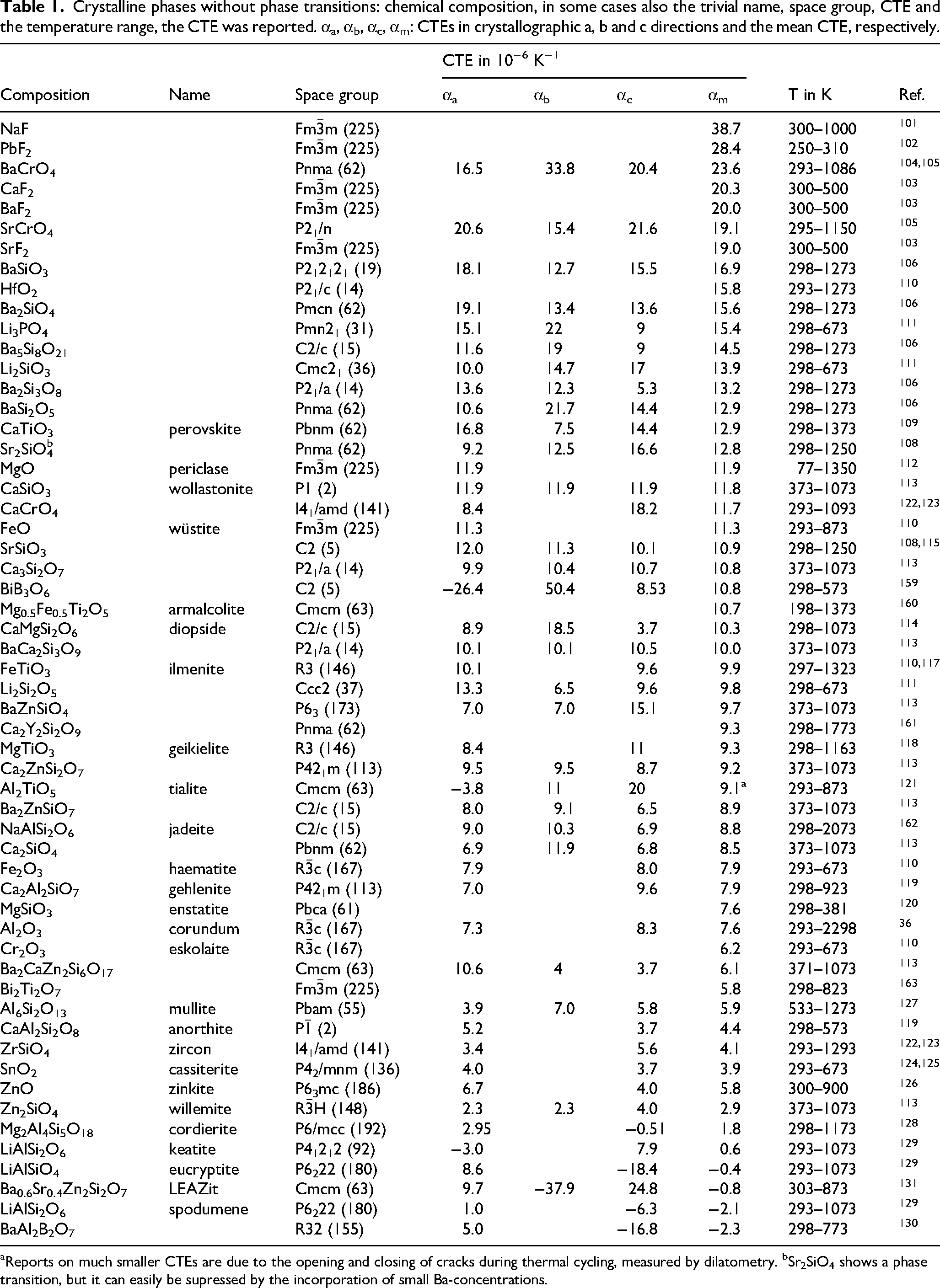
Crystalline phases without phase transitions: chemical composition, in some cases also the trivial name, space group, CTE and the temperature range, the CTE was reported. αa, αb, αc, αm: CTEs in crystallographic a, b and c directions and the mean CTE, respectively.
Reports on much smaller CTEs are due to the opening and closing of cracks during thermal cycling, measured by dilatometry. bSr2SiO4 shows a phase transition, but it can easily be supressed by the incorporation of small Ba-concentrations.
A frequent task is vacuum-tight sealing of metallic pins into metal housings: Here, the CTE of the copper pins is much larger than of the housing alloys. 99 The metallic housing has typically a tube shape and the sealing glass should have a smaller CTE than the housing metal. After cooling, the seal is under compressive stress, which is favourable for a glass-ceramic material. The copper is widely ductile during cooling and its CTE less important. This example demonstrates that the geometry of the materials to be joined may also play an important part and otherwise, a tailored design may help to overcome sealing problems.
Coefficients of thermal expansion of various crystalline phases
In the following, crystal phases are listed (see Tables 1 to 4) which can be crystallized from appropriate glass compositions. For example, crystalline phases, such as ZrW2O8 which has a negative coefficient of thermal expansion, 100 are not listed, because reports to crystallize them from glasses in quantities high enough to achieve low, zero or negative thermal expansion are not found in the literature. The Tables also include some phases which might be formed in minor quantities and possess CTEs not notably different from those of the desired phases and hence have not a detrimental effect. Some other phases might also be precipitated, but have CTEs very different from those of the desired phases and hence their precipitation should strictly be avoided.
Polymorphic phases in glass-ceramics with positive thermal expansion: chemical composition, in some cases also the trivial name, space group, CTE and the temperature range, the CTE was reported.
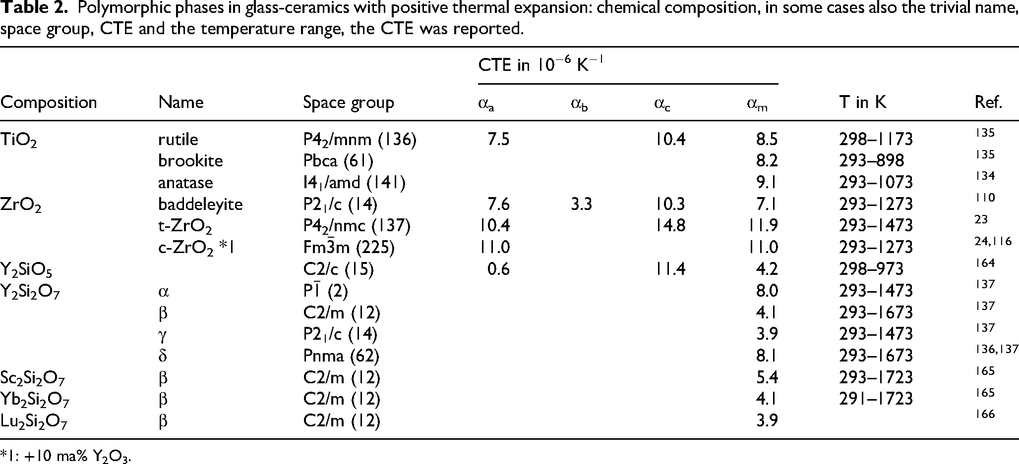
*1: +10 ma% Y2O3.
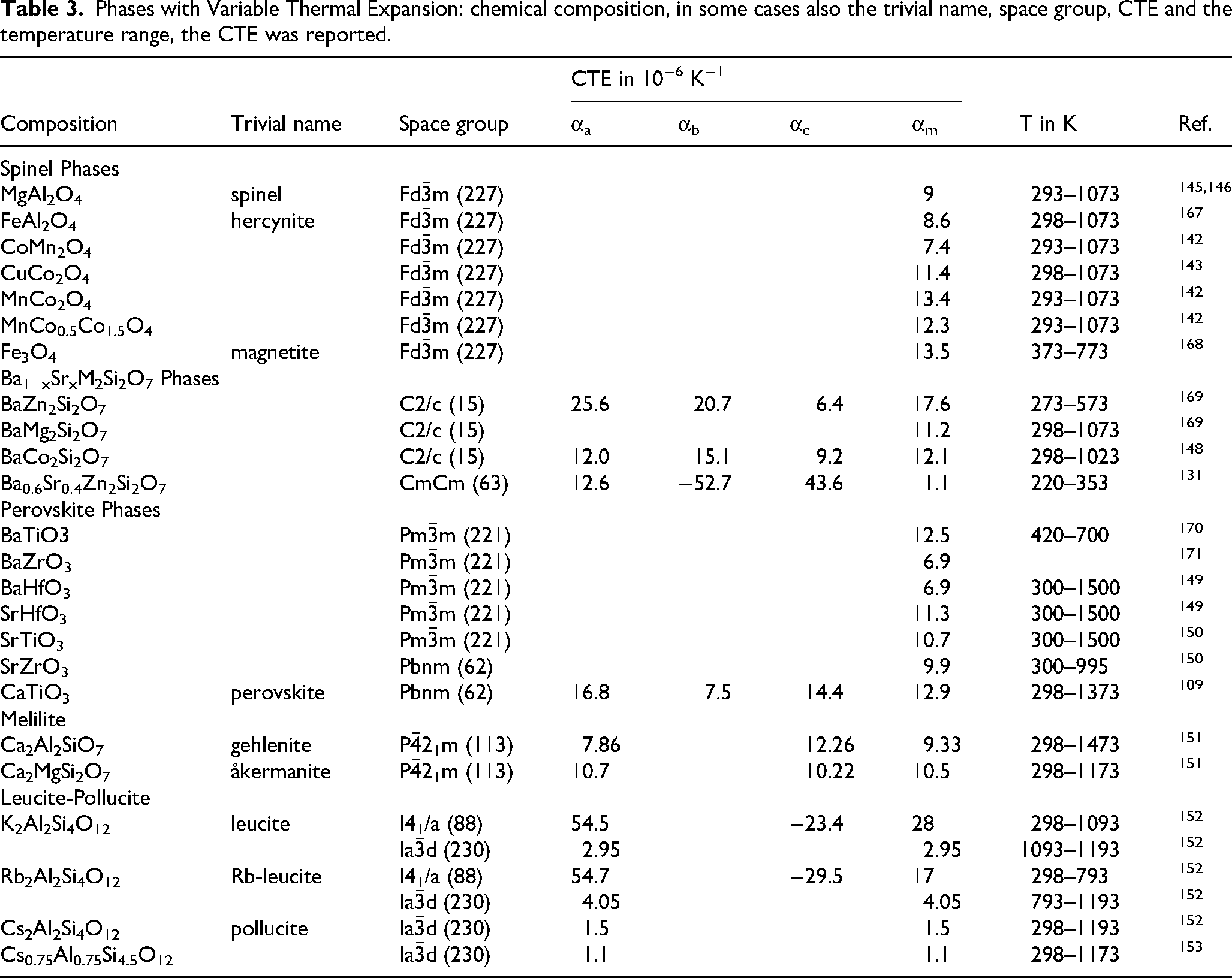
Phases with Variable Thermal Expansion: chemical composition, in some cases also the trivial name, space group, CTE and the temperature range, the CTE was reported.
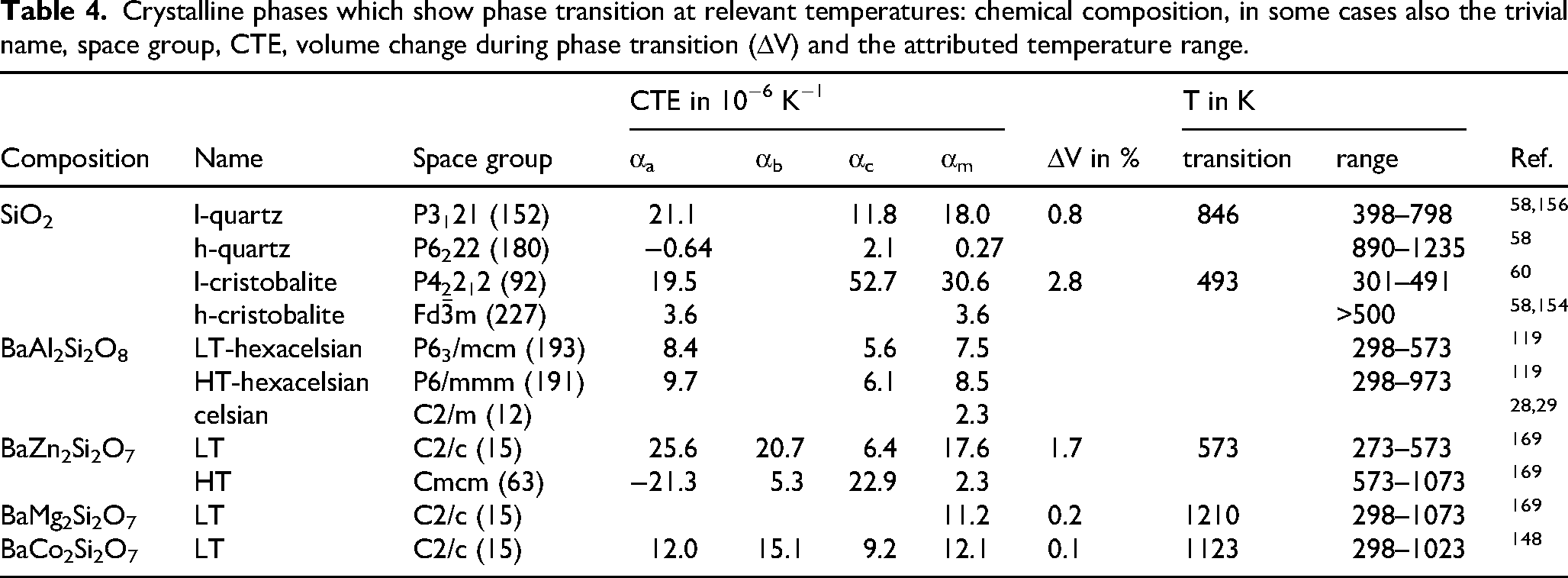
Crystalline phases which show phase transition at relevant temperatures: chemical composition, in some cases also the trivial name, space group, CTE, volume change during phase transition (ΔV) and the attributed temperature range.
In Table 1, binary, ternary and quaternary compounds are listed with their CTEs, the respective space group and the temperature ranges the CTEs were measured. If the compounds have not a cubic space group, in most cases (i.e., if found in the literature) also the CTEs in the respective crystallographic axes are listed as well as the mean linear CTEs. Please note that for monoclinic and triclinic space groups, the mean linear CTE is not necessarily identical with the mean CTE in the crystallographic axes, because also the angles between the crystallographic axes may change with temperature.
From the compounds listed in the Tables, the highest CTEs are observed in sodium fluoride, 101 lead fluoride, 102 alkaline earth fluorides, 103 BaCrO4 and SrCrO4104,105 which all are equal to or above 19·10−6K−1. Barium silicates possess CTEs in the range from 12 to 17·10−6K−1.106,107 Also, strontium orthosilicate, 108 CaTiO3, 109 HfO2, 110 Li3PO4 111 and Li2SiO3 111 possess CTEs in the same range. In the CTE range from 8 to 12·10−6K−1, MgO, 112 FeO, 110 wollastonite, 113 diopside, 114 SrSiO3,108,115 ZrO223,24,116 and some more alkaline earth silicates are found. 113 Many other silicate and titanate phases possess CTEs in the range from 7.5 to 10·10−6K−1.110,117,118 Here also alkaline earth zinc silicates, 113 lithium disilicate, 111 haematite, 110 gehlenite, 119 enstatite, 120 tialite, 121 and corundum 36 are found. Crystalline phases with CTEs between zero and 7.5·10−6 K−1 are Cr2O3, 110 Ba2CaZn2Si6O17, 113 ZrSiO4,122,123 SnO2,124,125 ZnO, 126 Zn2SiO4, 113 mullite, 127 anorthite 119 and cordierite. 128
Crystalline phases with CTEs below zero, i.e., with negative thermal expansion are mainly lithium alumosilicates with β-quartz structure, spodumene, eucryptite and keatite. 129 Glass-ceramics based on such phases are commercially available. Besides, also BaAl2B2O7, 130 Ba0.5Sr0.5Zn2Si2O7 131 and solid solutions derived hereof132,133 possess negative thermal expansion and can be crystallized from glass in high concentrations.
In Table 1, also the CTEs (for the non-cubic phases) in different crystallographic directions are given. Phases with highly anisotropic CTEs, where the largest and the lowest CTE differ by at least the factor two are BaCrO4, CaCrO4, Ba2Si3O8, Ba5Si8O21, BaSi2O5, CaTiO3, CaMgSi2O6, BaZnSiO4 and Ba2CaZn2Si6O17.
In Table 2, chemical compositions are listed which can be precipitated from glasses in different crystal structures, depending on the other glass components and/or the crystallization conditions. Here, TiO2,134,135 ZrO2,23,24,110 and rare earth silicates are listed. Especially in the case of Y2Si2O7,136,137 many different phases with very different CTEs may occur. If phases, which are thermodynamically not stable under the applied conditions are formed,138–141 it is very difficult to predict the CTE of a crystallized glass from its composition. Furthermore, during applications at high temperature, the polymorphs might transfer to other ones and the CTE may change.
Table 3 presents some phases which form solid solutions in wide concentration ranges. Here, spinel,110,142–146 alkaline earth zinc silicate phases,7,8,85,131,133,147,148 perovskites,30,109,149,150 melilite 151 and leucite-pollucite152,153 are listed. In the alkaline earth zinc silicates, the CTE can be varied in a wide range from negative to strongly positive. 132 This is due to the occurrence of a high and a low temperature phase. The low temperature phase has a high CTE, while the CTE of the high temperature phase is negative. In the compound BaZn2Si2O7, the transition temperature is around 280 °C, which is accompanied by a large volume expansion of 3.5% (positive during heating). The transition temperature can be shifted to higher temperatures by the partial or total substitution of ZnO by MgO or oxides of divalent transition metals, such as CoO, NiO, MnO or CuO. The substitution results in phase transition temperatures of even above 950 °C and a strong decrease of the volume effect running parallel to the phase transition. If, however, BaO is partially substituted by SrO, the transition temperature is shifted to lower temperatures, even below room temperature. Then, negative CTEs at room temperature and above are observed. The alkaline earth zinc silicate phases possess strongly anisotropic CTEs.
Anisotropy is of course not observed if the phases possess a cubic space group. This is the case for oxides with perovskite (space group Pm
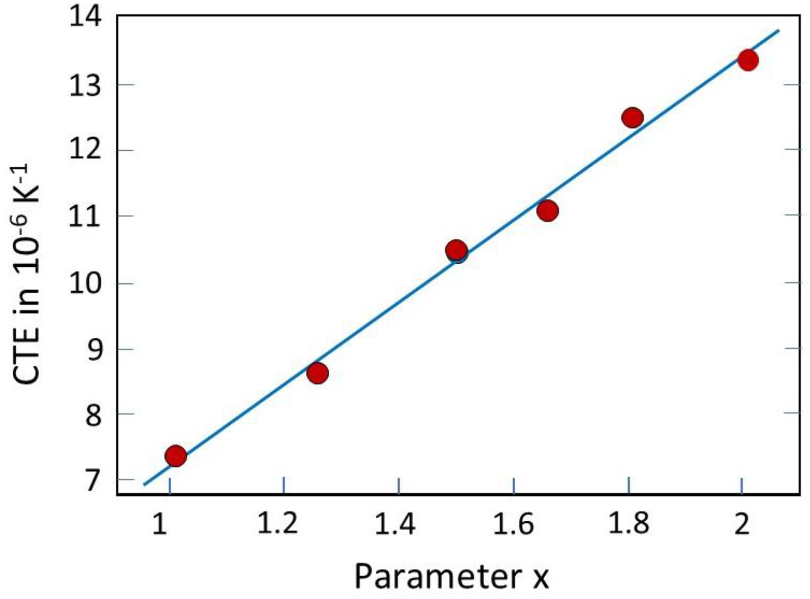
Coefficient of thermal expansion in the solid solutions series CoXMn3−XO4. Redrawn after Ref. 142
In Table 4, crystalline phases are listed which show a phase transition accompanied by a notable volume effect. This is of special importance, if this phase transition occurs at a temperature below Tg of the residual glass phase, because then the stresses forming during cooling cannot relax by viscous flow. The two best investigated phases which show martensitic phase transitions at comparatively low temperatures are cristobalite58,60,154,155 and quartz.58,156
Pure quartz shows an α/β-transition at 573 °C with a volume effect of ΔV = 0.8%. 59 The latter can be suppressed by the incorporation of Al2O3 (typical: 10 mol%) and an equimolar concentration of, e.g., Na2O, Li2O, MgO or ZnO. Then AlO4− tetrahedra replace the SiO4 tetrahedra and charge compensation of the negatively charged AlO4− tetrahedra is achieved by the alkali, alkaline earth, zinc or other divalent transition metal cations. The α-quartz phase shows a CTE of around 10 to 12·10−6K−1 in the range of 100–300 °C, and decreases to 5–6·10−6 K−1 above 550 and 800 °C. The CTEs of the β-quartz and the β-quartz solid solutions are low or even negative as, e.g., in the case of Li2O incorporation. That means, while incorporating Al2O3 and, e.g., Li2O, the phase transition during cooling does no longer occur and accordingly, the CTE is low or even negative. Otherwise, if these compounds are not incorporated, the phase transition during cooling with the large volume effect takes place and if that happens below Tg of the residual glass phase, high internal stresses are formed which result in high mechanical strength and fracture toughness.46,48 The α/β-transition of cristobalite occurs at temperatures in the range from 180 to 270 °C and is accompanied by an even higher volume effect of ΔV = 2.8%. 59 Since this volume effect and also the resulting stress are usually too high, it is difficult to prepare partially crystalline materials with high cristobalite concentrations. By contrast to the quartz phase, the stabilisation of the high temperature cristobalite phase is much more difficult. 155 Nevertheless, it can, under certain conditions be achieved by the incorporation of CaO and alumina 157 or by AlPO4. 158 Then a low CTE and mechanically stable samples can be obtained.
Coefficients of thermal expansion of crystallized glass seals
The seal should initially be a glass and hence, considerable quantities of network formers must occur. That means, that the main crystalline phases should also contain network formers, in most cases silicates.
The coefficients of thermal expansion of crystallized glass seals are, first of all, a function of the CTEs and volume concentration of the present crystalline and glassy phases. For the calculation of the CTE of the seal, a simple “rule of mixture” is given in equation (13):
With: indices s, g, and i: seal, glass and crystalline phase “i”, fi = volume fraction of the crystalline phase “i”. In principle, if the chemical compositions of the crystallized phases and their volume concentrations as well as the initial chemical composition of the glass are known, the composition of the residual glass can be calculated. The latter can also be analytically determined using electron microscopic techniques, such as energy-dispersive X-ray spectroscopy (EDXS).
Equation (13) does not take into account the Young's Moduli and the Poisson's Ratios of the respective phases. If non-cubic phases with notably anisotropic CTEs, Young's Moduli and Poisson's Ratios occur, equation (13) cannot be more than a first approximation. Furthermore, in these cases, the microstructure plays an important role.
Depending on the aimed CTE, the softening temperature of the crystallized glass seal as well as on the respective application temperature, very different glass systems have to be chosen. Some of them have already been proposed long time ago and are also industrially produced. If the processing temperature is not the problem with the materials to be sealed and the application temperature is <500 °C, usually crystallizing glass seals are not required, because glass seals which do not crystallize are sufficient.
A serious problem are changes in the phase composition of the seal during application. The most common case is that the crystallization process is not yet completed during sealing and proceeds during application. This results in an increase of the volume concentration of the crystalline phase(s) and sometimes also in the formation of further crystalline phases. This in turn may give rise to an undesired change in the CTE and to an increasing mismatch of the CTE of the seal and the sealed material.
In Figure 8, occurring changes of the CTE during proceeding crystallization are shown for lithium disilicate glasses of different Li/Si ratio. The CTEs were calculated from the respective volume concentration and the CTEs of Li2O·2 SiO2 and of the lithium silicate glass (obtained from SciGlass 172 ) applying the simple mixing rule shown in equation (13). Please note that for a glass which contains less Li2O than stoichiometric lithium disilicate, SiO2 is enriched during the course of the crystallization. This results in a notable decrease of the CTE of the residual glass phase. For a stoichiometric glass 33.3 Li2O·66.6 SiO2, the CTE of the glass-ceramic decreases during crystallization from 12.1·10−6 K−1 to 10.4·10−6 K−1 for a volume concentration of 75%. If the glass contains less Li2O, the decrease is more pronounced and already for a glass with the composition 30 Li2O·70 SiO2, the CTE decreases from 11·10−6 K−1 to 7.6·10−6 K−1 for a volume concentration of 71%. This highlights that also minor changes in the chemical composition of crystallizing glass seals may have a drastic effect.
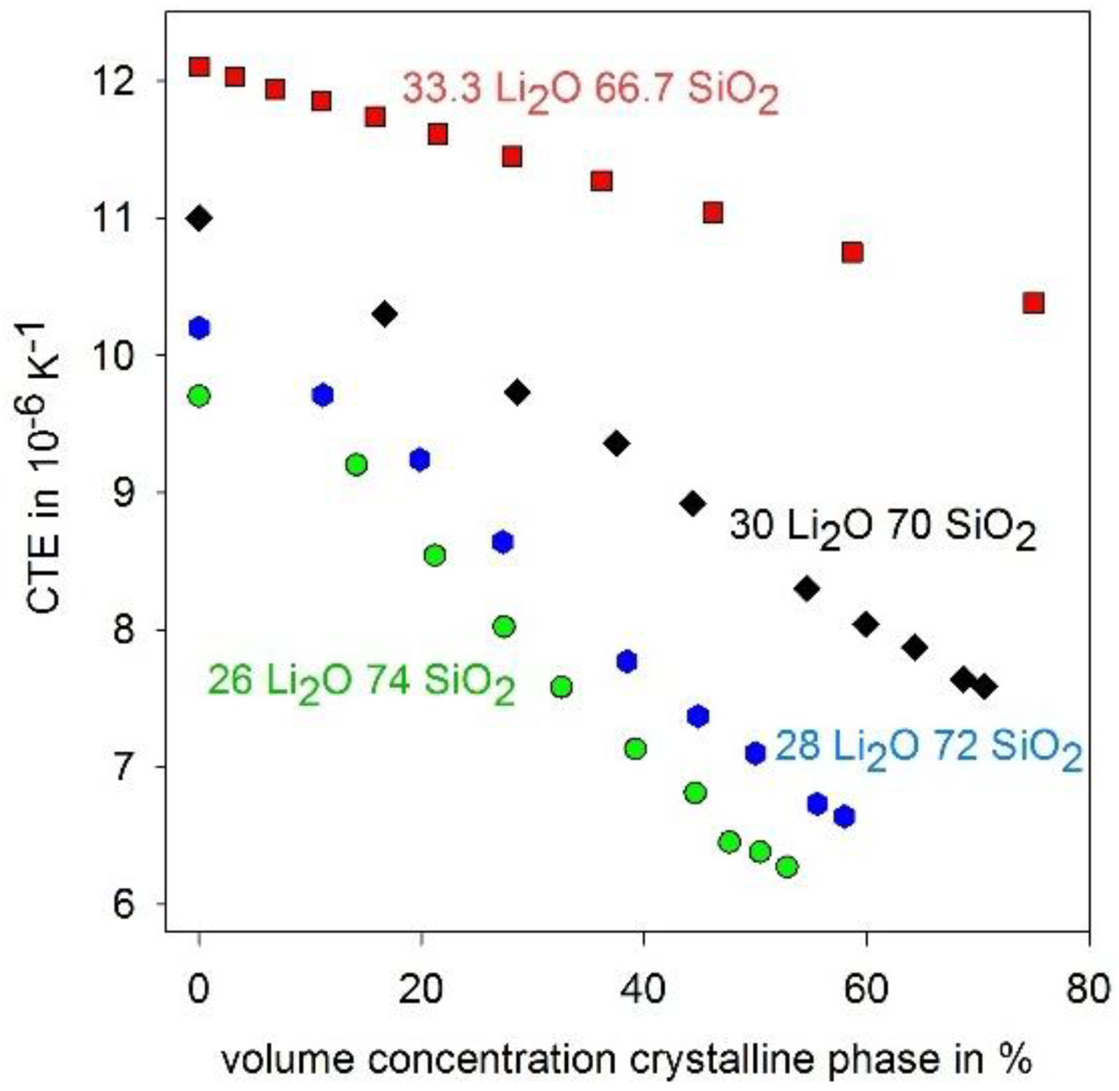
Calculated CTEs of glasses in the Li2O·SiO2 system with different stoichiometry during the course of the crystallization process.
It should be noted that this simple calculation is not suitable to fully describe all effects which may contribute to a change in the CTE. Among these effects, the crystallization of other phases in this case of SiO2 phases such as quartz or cristobalite from the residual glass phase should be mentioned.
The best way to avoid changes in the CTE during application, is the crystallization of solid solutions which incorporate all present glass components. An example for this is the crystallization of an åckermanite/gehlenite solid solution. The SEM micrographs and attributed EDX patterns are shown in Figure 9. Please note that near the grain boundaries, Ca is depleted, while Mg and Zn are enriched, nevertheless, Si is not enriched neither near the grain boundaries, nor in any other region of the microstructure. The dilatometric curves are shown in Figure 10 for samples crystallized at 935 and 1135 °C for 1 and for 80 h. It is seen that only minor changes of the thermal expansion are observed.
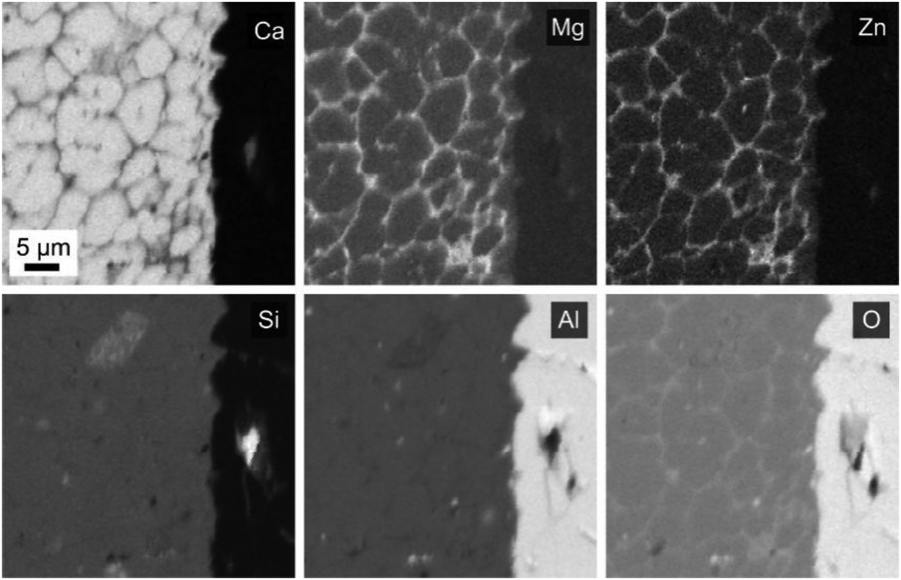
EDX maps of Ca, Mg, Zn, Si and Al recorded near the interface of an Al2O3 ceramic and a crystallizing glass seal with the mol% composition 4.2 MgO·5.0 ZnO·44.1 CaO·26.7 Al2O3·20.0 SiO2. Reprinted with permission from Ref. 95 from Springer Nature.
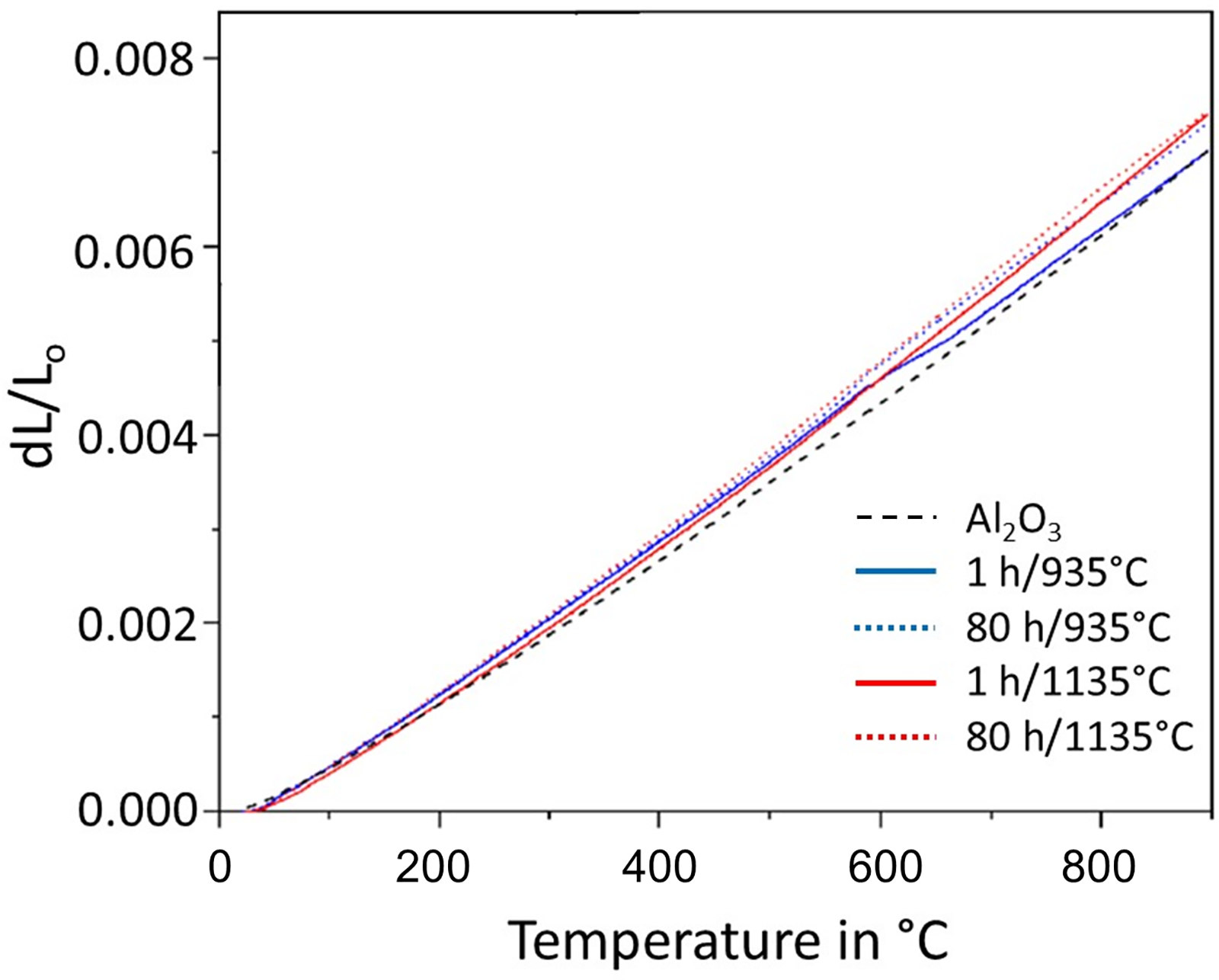
Thermal expansion curves of glass-ceramics with the mol% composition 4.2 MgO·5.0 ZnO·44.1 CaO·26.7 Al2O3·20.0 SiO2 crystallized at 935 and 1135 °C for 1 and 80 h in comparison to an Al2O3 ceramic. Redrawn from Ref. 95
Crystallizing glass seals with CTEs <5·10−6 K−1
Crystalline phases which may act as main components of a crystallized glass seal and possess CTEs close to zero or even negative are mainly β-quartz, β-cristobalite, keatite, β-spodumene, β-eucryptite and keatite. Most of these compositions are based on lithium alumosilicates. Li+ can partially be replaced by Na+ or divalent cations, such as Zn2+ or Mg2+. Besides these compositions, also BaAl2B2O7, and solid solutions based on Ba1−xSrxZn2Si2O7 are suitable phases to achieve low CTEs.
Such crystallizing glass seals are required if, e.g., pure SiO2 glass or glass-ceramics with CTEs close to zero are to be sealed. It should be noted that for this purpose, non-crystallizing glass seals are not suitable, because the only glass compositions with such low CTE are pure SiO2 or SiO2/TiO2 glasses173,174 which, however, possess too high softening temperatures (for SiO2 glass: 1740 °C 175 ). For the sealing of lithium alumosilicate based glass-ceramics, also glasses from the same system with somewhat lower softening point are suitable. The lower softening point can be achieved by an increase of the alkali oxides concentration and/or the addition of few mol% B2O3. Careful optimisation of the crystallization conditions of the seal is necessary to tailor the CTE. For applications at high temperatures, such as furnace windows, the crystallization process of the seal might proceed and the CTE may change.
Materials with CTEs between 2 and 5·10−6 K−1 are for example silicon nitride (CTE: 3–4·10−6 K−1165,176) and silicon carbide (CTE: 4–5.5·10−6 K−1176,177). Some studied crystallizing sealing glasses are based on rare earth silicates, which are also used as oxidation protecting coatings for silicon carbide and silicon nitride.165,176,177 Other glass seals contain crystalline CaAl2Si2O6, MgSiO3, or Mg2Al4Si5O18, which possess CTEs of 4.4, 7.4 and 1.8·10−6 K−1 (see Table 1).
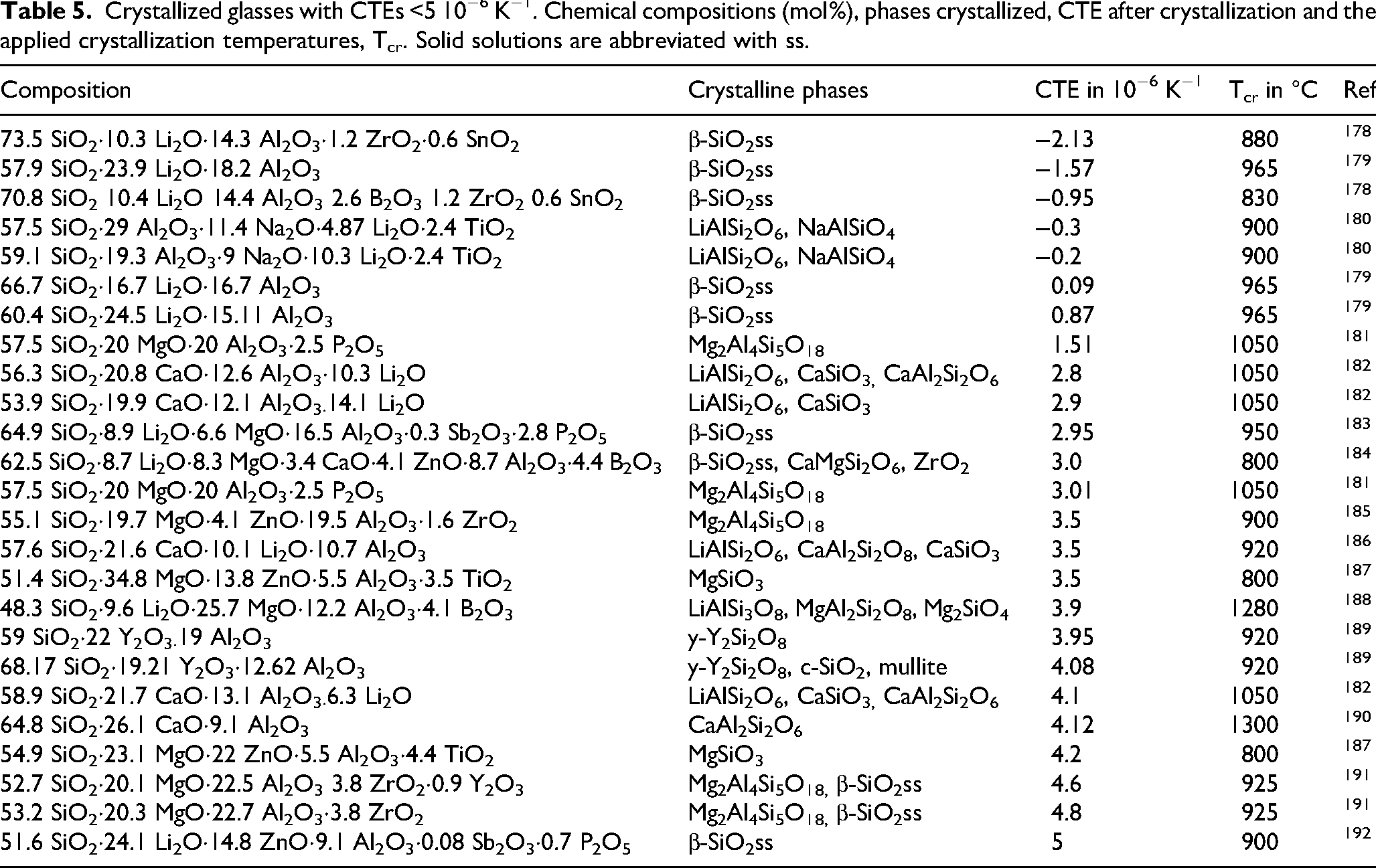
Some particular chemical compositions of crystallizing glasses and the formed crystalline phases as well as the attributed CTEs are summarised in Table 5. Most of the glasses listed were not originally developed for use as glass seals. Accordingly, they are only suitable for use as solder to a limited extent. In the LAS system in particular, the glasses were developed for the production of volume-crystallizing glass-ceramics, which may counteract good compaction due to a strong tendency to crystallization. The following compositions are therefore intended to provide an overview of possible compositions, although it has not been assessed whether these compositions are suitable for use as seals. Ultimately, this also depends on the material pairings to be joined, the allowed maximum sealing temperatures and other parameters.
Crystallized glasses with CTEs <5 10−6 K−1. Chemical compositions (mol%), phases crystallized, CTE after crystallization and the applied crystallization temperatures, Tcr. Solid solutions are abbreviated with ss.
Crystallizing glass seals with CTEs between 5 and 9·10−6 K−1
Crystallized glass seals with CTEs between 5 and 9·10−6 K−1 are frequently required, e.g., for the sealing of Al2O3. Table 6 shows some chemical compositions of crystallizing glass seals and the phases formed during crystallization as well as the resulting CTEs. In the seals, a large variety of different crystalline phases is formed. Since many crystalline phases which can be crystallized from glasses (see Table 1) possess CTEs in this range, a required CTE can be obtained by many different glass compositions. Hence, it is possible to choose an optimum composition by other criteria, such as corrosion behaviour, adherence to the materials to be sealed, electric conductivity or mechanical properties.
Crystallized glass seals with CTEs between 5 and 9·10−6 K−1. Chemical compositions (mol%), phases crystallized, CTE and the crystallization temperature, Tcr.
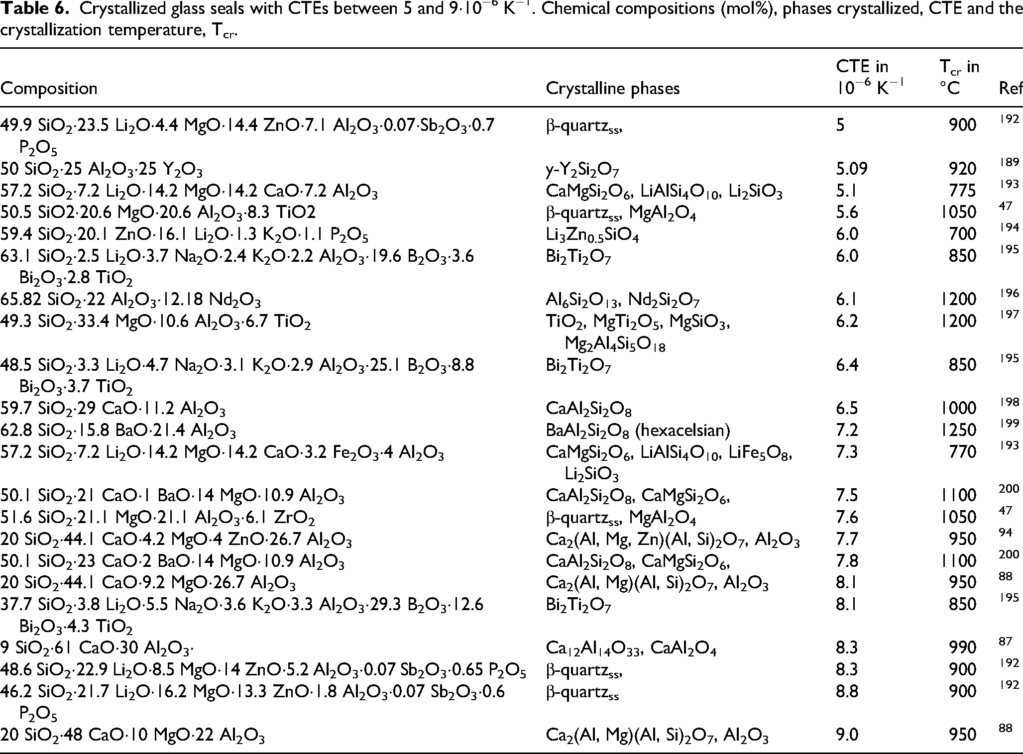
Numerous crystalline phases are found in crystallized glasses with appropriate CTEs. Among these, CaAl2Si2O6, CaMgSi2O6, Li2SiO3, MgAl2O4, Bi2Ti2O7, Al6Si2O13 and CaAl2O4 are to be mentioned (see Table 6).
Many commercial sealing glasses exist for this CTE range; unfortunately, the chemical compositions and the phases formed are scarcely reported in literature.
Crystallizing glass seals with CTEs >9·10−6 K−1
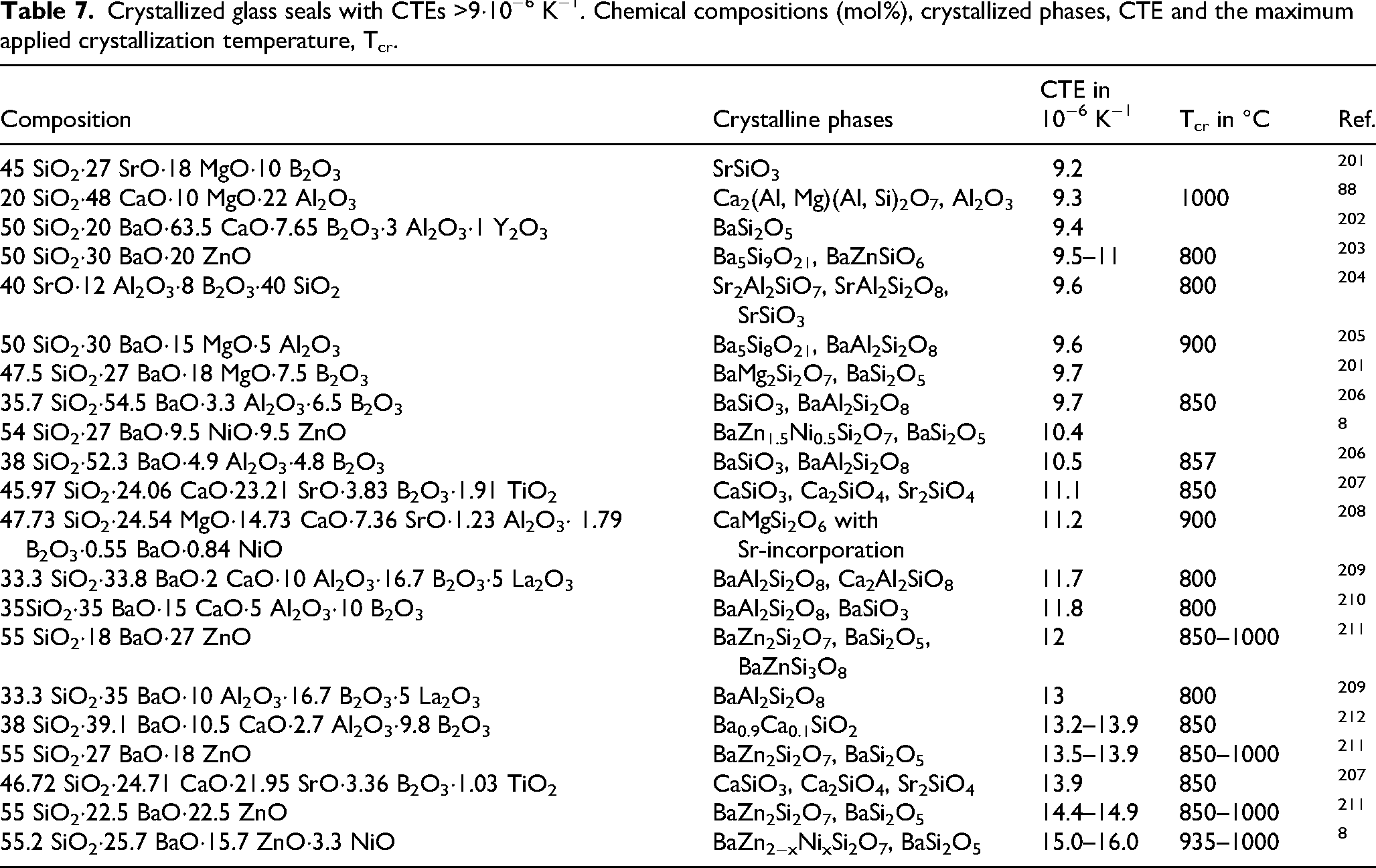
Crystallizing glass seals with such high CTEs are predominantly required for joining of high temperature fuel cell materials or for high temperature alloys such as CroFer™ or NiCroFer™. The high CTE phases crystallized from the seals are frequently based on alkaline earth silicates. Here, especially, the barium silicates Ba2SiO4, BaSiO3, Ba5Si8O21, Ba2Si3O8 and BaSi2O5, as well as the strontium silicates Sr2SiO4 and SrSiO3 are to be mentioned. A drawback, especially of barium containing phases used for sealing of chromium containing alloys is that under certain circumstances, BaCrO4 is formed, a phase with a mean CTE as high as 23.6·10−6 K−1, which furthermore shows very different CTEs in different crystallographic directions. If this phase is formed, at the interface metal/seal cracking of the interface may occur. Other sealing glasses with CTEs > 10·10−6 K−1 contain some binary alkaline earth silicates, such as CaSiO4, Ca3Si2O7 as well as BaCa2Si3O9 and BaZnSiO4 which all possess CTEs > 10·10−6 K−1. Some crystallized glasses with high CTE also contain the alkaline earth alumosilicates SrAl2Si2O8 or BaAl2Si2O8.
Among the ternary alkaline earth silicates, åkermanite (Ca2MgSi2O7, 10.5·10−6 K−1) and other members of the melilite family have also high CTEs. Åkermanite is a favourable crystalline phase for two reasons: first, although it possesses a tetragonal space group, the CTEs of the a- and c-axes are 10.7 and 10.2·10−6 K−1, respectively and hence are nearly isotropic. The second reason is the formation of solid solutions; it can incorporate numerous transition metal oxides at Mg-sites as well as Al3+ at Si4+ sites, which may contribute to a higher volume concentration of crystalline phase. Compounds added as nucleation inhibitor which widens the glass forming range such as Al2O3 can then be incorporated into the crystalline phase.
A special system are solid solutions of BaZn2Si2O7, in which ZnO is at least partially replaced by other transition metal oxides. Although, the CTE can easily be tailored by the chemical composition, these solid solution phases possess a strongly anisotropic CTE and hence a fine-grained microstructure is required. Other phases with high CTE are e.g., fluorides of Na, Pb, Ba, Sr or Ca. These phases can be crystallized from oxyfluoride glasses, however, usually not in concentrations higher than 10 wt% and are typically not used and studied for sealing applications but, e.g., for optical applications, such as PTR (photo-thermo-refractive) glasses. Nevertheless, such fluorides may precipitate, if blowing is to be suppressed by the addition of fluorides to the glass batch and hence may affect the CTE.
Table 7 presents some chemical compositions of sealing glasses with CTEs >9·10−6 K−1, the formed crystalline phases, the resulting CTEs and the crystallization temperatures.
Crystallized glass seals with CTEs >9·10−6 K−1. Chemical compositions (mol%), crystallized phases, CTE and the maximum applied crystallization temperature, Tcr.
Interface and reactive sealing
In principle, all sealing processes lead to a reaction of the sealing glass with the materials to be joined. Especially if oxidic materials such as ceramics are to be joined, at the interface to the seal, chemical reactions take place. The most common is a slight dissolution of the ceramics in the sealing glass, which leads to a chemical gradient near the interface. This also results in a change of the CTE, i.e., a gradient in the CTE near the ceramics is formed and the crystallization behaviour of the seal changes. Usually, these diffusion gradients do not lead to a pronounced deterioration of the interface. The extent of the dissolution of the materials to be joined can widely be affected by the applied sealing technique, i. e. by the temperature/time schedule.
Strongly adherent seals are frequently observed if ceramics are sealed. As an example, an SEM micrograph is shown in Figure 11 where a tetragonal ZrO2 ceramic is sealed with a crystallizing seal with the mol% composition 47.4 BaO·30.6 SiO2·6.4 Al2O3 15.6 B2O3. 206 The ceramic is well wetted by the seal, some bubbles are seen in between the ceramic and the seal, cracks are not observed. In the crystallized seal some pores are visible due to incomplete sintering.
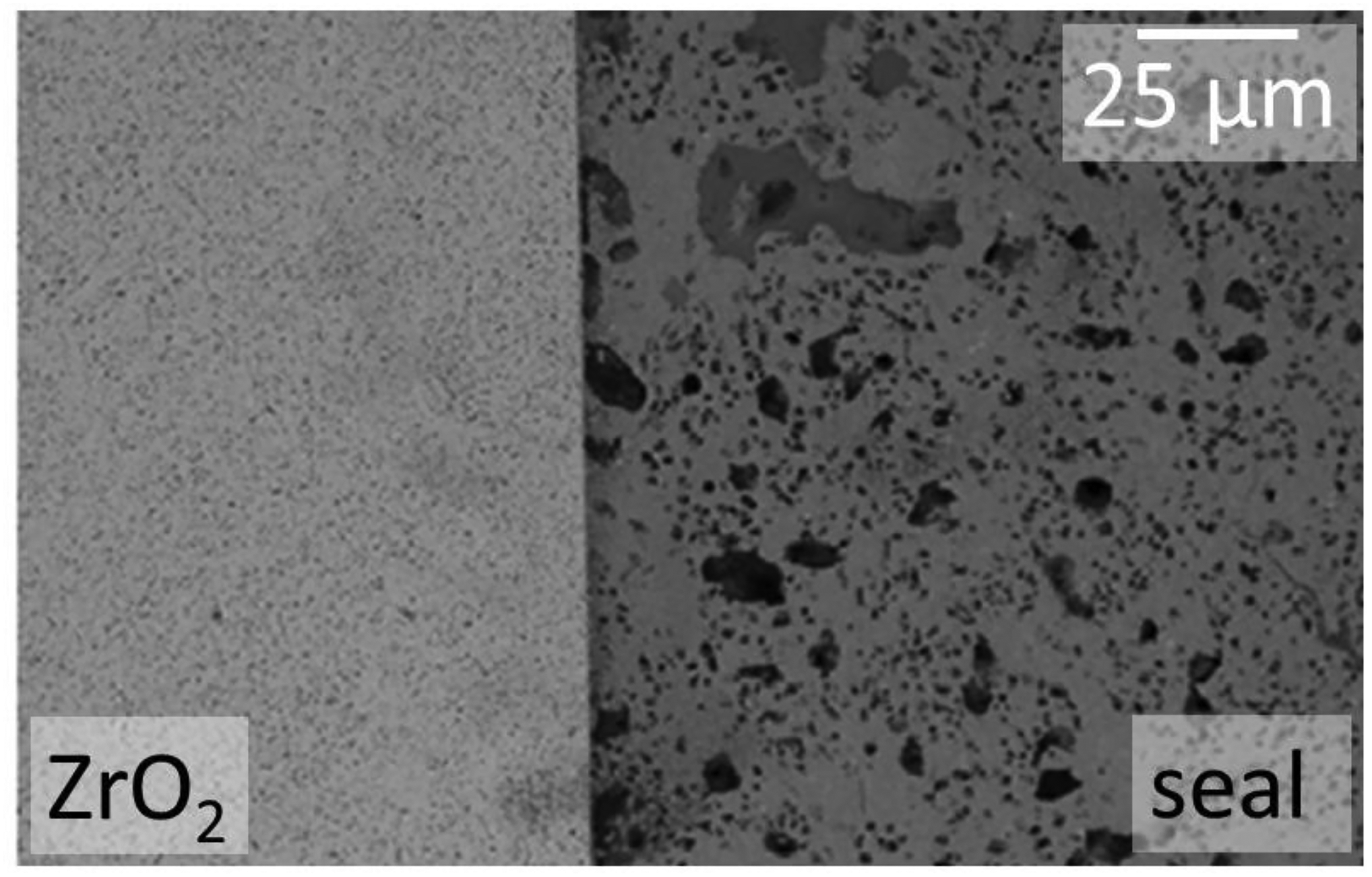
SEM micrograph of the polished glass–ceramic/zirconia interface cross-section of a glass with the mol% composition 47.4 BaO·30.6 SiO2·6.4 Al2O3 15.6·B2O3 after thermal treatment at 850 °C for 2 h. Reprinted with permission from Ref 206 from Elsevier.
Another example (see Figure 12) shows a β-Al2O3 ceramic sealed by a glass with the mol% composition of 37.7 SiO2·3.3 Al2O3·29.3 B2O3·3.8 Li2O·5.5 Na2O·3.6 K2O·4.3 TiO2·12.6 Bi2O3, which was crystallized at 700 °C for 8 h. 195 In this case, a complete wetting by the seal is observed, bubbles or cracks are not observed.
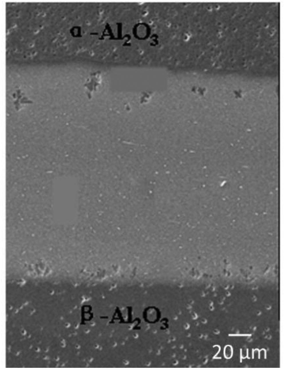
SEM micrograph of a cross-section of β-Al2O3 ceramics sealed by a glass with the mol% composition of 37.7 SiO2·3.3 Al2O3·29.3 B2O3·3.8 Li2O·5.5 Na2O·3.6 K2O·4.3 TiO2·12.6 Bi2O3, crystallized at 700 °C for 8 h. Reprinted with permission from Ref. 195 from Elsevier.
If an alloy is sealed with a crystallizing glass seal, some of the metallic components can be enriched at the interface. One example is shown in Figure 13, where a ferritic stainless steel (Sanergy HT) is sealed to a crystallizing glass with the mol% composition 19.45 CaO·24.31 MgO·2.43 BaO·1.22 Al2O3·1.21 La2O3·46.18 SiO2·4.38 B2O3·0.82 NiO thermally treated at 850 °C for 1 h and subsequently at 800 °C for 300 h. 213 Immediately at the interface, some Cr and Mn are enriched, supposedly as oxides, possibly as MnCr2O4 spinel. The layer was reported to act as diffusion barrier which hinders further oxidation of the steel.
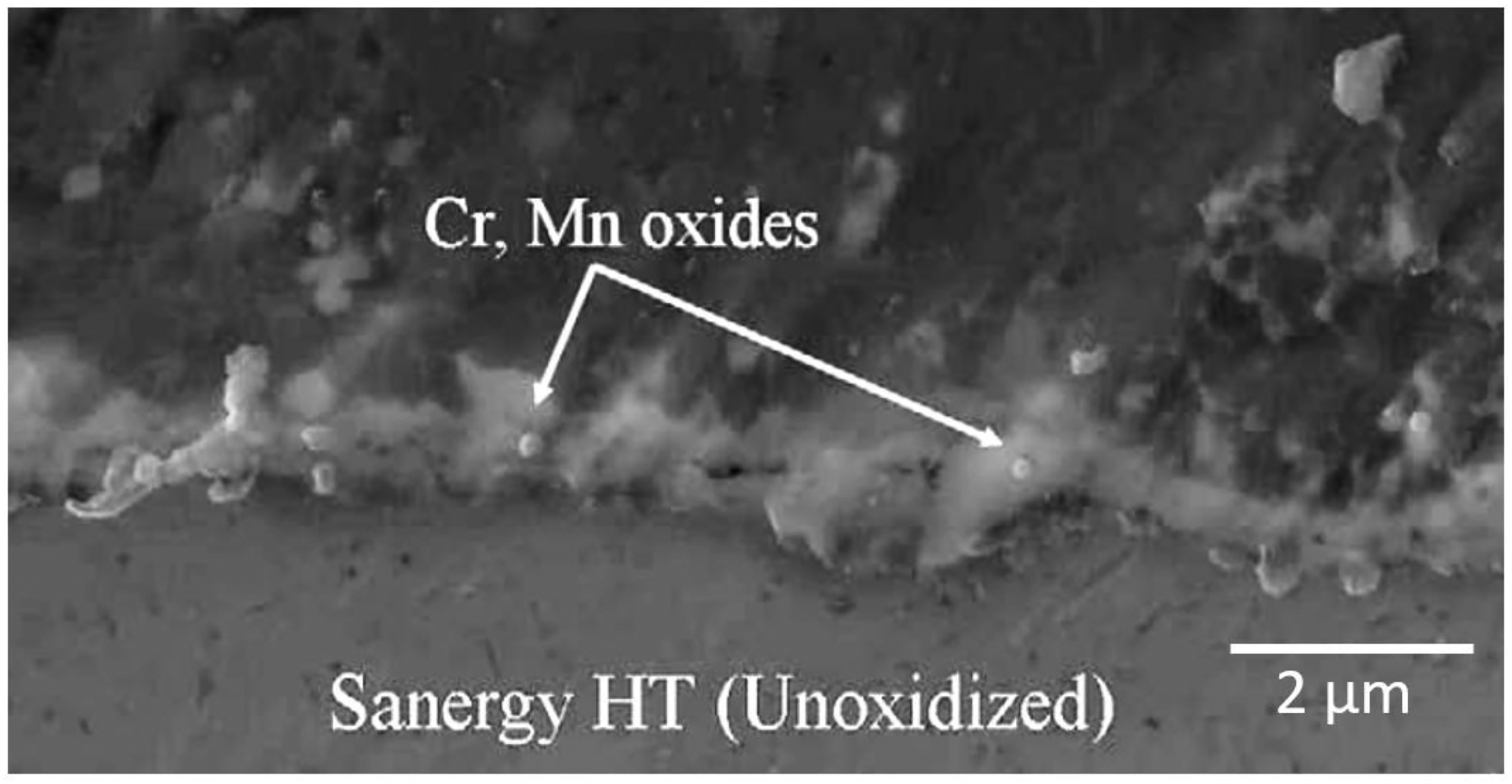
SEM micrograph (left) and EDX mappings of Cr (left top) and Mn (left bottom) of the interface of the alloy Sanergy MT and a crystallizing glass seal with the mol% composition 19.45 CaO·24.31 MgO·2.43 BaO·1.22 Al2O3·1.21 La2O3·46.18 SiO2·4.38 B2O3·0.82 NiO. Reprinted with permission from Ref. 213 from Elsevier.
Another quite common effect of the interface is nucleation of glass components, which gives rise to crystallization in the glass. Here, the crystals frequently grow with their fastest growing axis perpendicular to the interface and hence give rise to some crystal orientation, which also results in an anisotropy of the CTE. This means that the mean CTE perpendicular to the interface is no longer equal to the mean CTE of the crystalline phase but approaches that perpendicular to the fastest growing axis. That also leads to a stress profile near the interface different from that in a homogeneously crystallized glass.
The seal does not necessarily crystallize from the surface and hence does not possess a preferred orientation, as illustrated in Figure 14 for an Al2O3 (see bottom of Figure 14 left and middle) ceramic sealed by a glass with the mol% composition 4.2 MgO·5.0 ZnO·44.1 CaO·26.7 Al2O3·20.0 SiO2. 95 During laser sealing, an åkermanite/gehlenite solid solution (AGSS) with the tetragonal space group P421m (113) is crystallized. Besides trace quantities of some other crystalline phases, such as gahnite/spinel (ZnAl2O4/MgAl2O4) solid solutions, as shown in the Electron Backscatter Diffraction (EBSD) phase map presented in Figure 14 left. In Figure 14 middle, an Inverse Pole Figure Map is presented, which shows that the AGSS grains possess very different colours and hence very different orientations. This is better illustrated in the Pole Figure shown in Figure 14 right, where randomly distributed orientations can be seen.
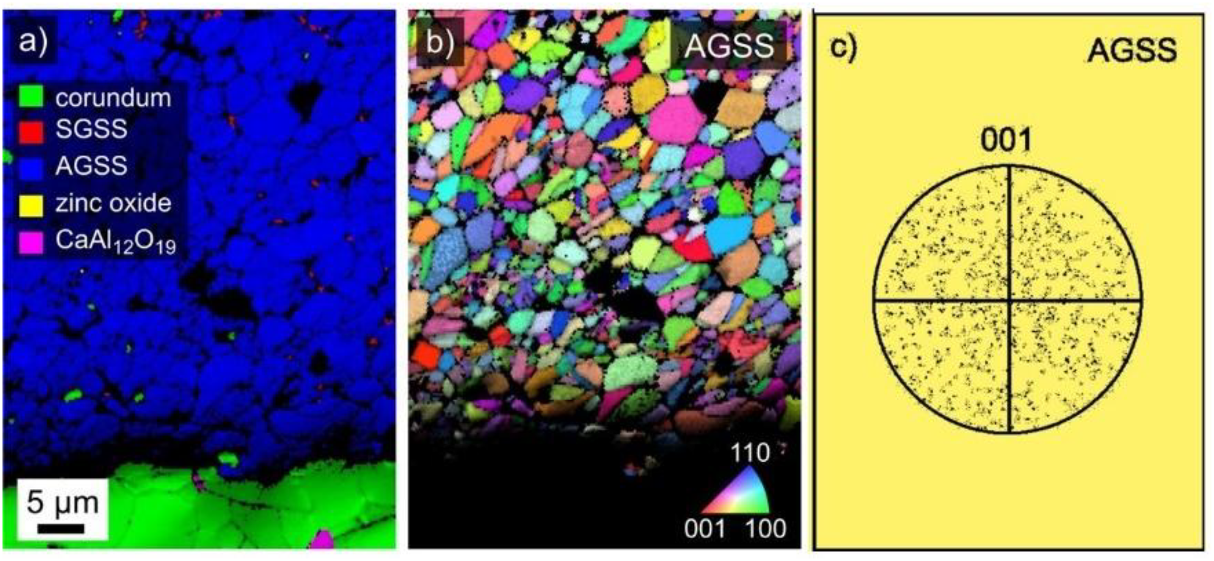
Results from EBSD recorded near the interface of an Al2O3 ceramic and a crystallizing glass seal with the mol% composition 4.2 MgO·5.0 ZnO·44.1 CaO·26.7 Al2O3·20.0 SiO2. Left: EBSD phase map: blue åkermanite/gehlenite solid solutions (AGSS); green corundum. Middle: inverse pole figure map. Right: pole Figure. Reprinted with permission from Ref. 95 from Springer Nature.
Other interfacial reactions are due to redox reactions between the glass and metals to be joined. A prerequisite for such reactions is the presence of a redox partner in the glass composition which might be reduced, while at least one component of the metal is oxidised. A redox partner always present in glass is water, which e.g., might be reduced to gaseous hydrogen e.g., by the oxidation of Cr from an alloy according to equation (14).
214

Similar reactions were also reported to take place, if Ti, Y, Ta are components of the alloy to be sealed. 214 The formation of hydrogen might give rise to bubble formation at or near the interface.
Another component frequently present in sealing glasses is P2O5, e.g., added as nucleation agent. Then a redox reaction according to equation (15) may take place
214
:
Depending on the conditions supplied, besides Ti4P3 also TiO and/or TiO2 might be formed. 215 These reactions are also of importance, if metallic Ti should be coated with bioactive glass-ceramics in order to enhance bioactivity.
Similar reactions might also occur with SiO2 of the sealing glass
215
:
The reaction with a borate glass is shown in equation (17)
214
:
Pre-oxidation of the metal may hinder or even completely avoid such reactions, but might also lead to a weakening of the interface metal/glass ceramic.
If the glass composition contains components such as CoO, NiO or CuO, which are easy to reduce, also steel and any iron or chromium containing alloy can be oxidised and metals such as Co, Ni or Cu are formed, according to equation (18).
With M = Co, Ni or Cu.
These components, especially CoO are used in enamelling (ground enamels) since centuries and help to increase the adherence of the enamel to some metal alloys. 216
In the following, reactive sealing of a metal with a crystallizing glass seal is described, in order to overcome insufficient wetting of metals by crystallizing glass seals. In the literature, a route is described which uses NiO or CoO as a component of the sealing glass.7,217 During sealing, a redox reaction between metallic components which are easy to oxidise and the seal takes place. While Co2+ or Ni2+ is reduced to the metal, components of the alloy, such as Fe, Cr or Al are oxidised (see equation (18)).
This is schematically shown in Figure 15. The metal is heavily corroded and shows pronounced pitting. The cavities next to the interface are filled with oxides of iron, aluminium or chromium, while in the seal, spherical particles of cobalt or nickel are observed. At the immediate interface, those elements oxidised from the metallic phase are enriched, their concentrations decline with increasing distance from the interface. During sintering or in a subsequent thermal treatment, the seal is crystallized and the desired phase is formed.
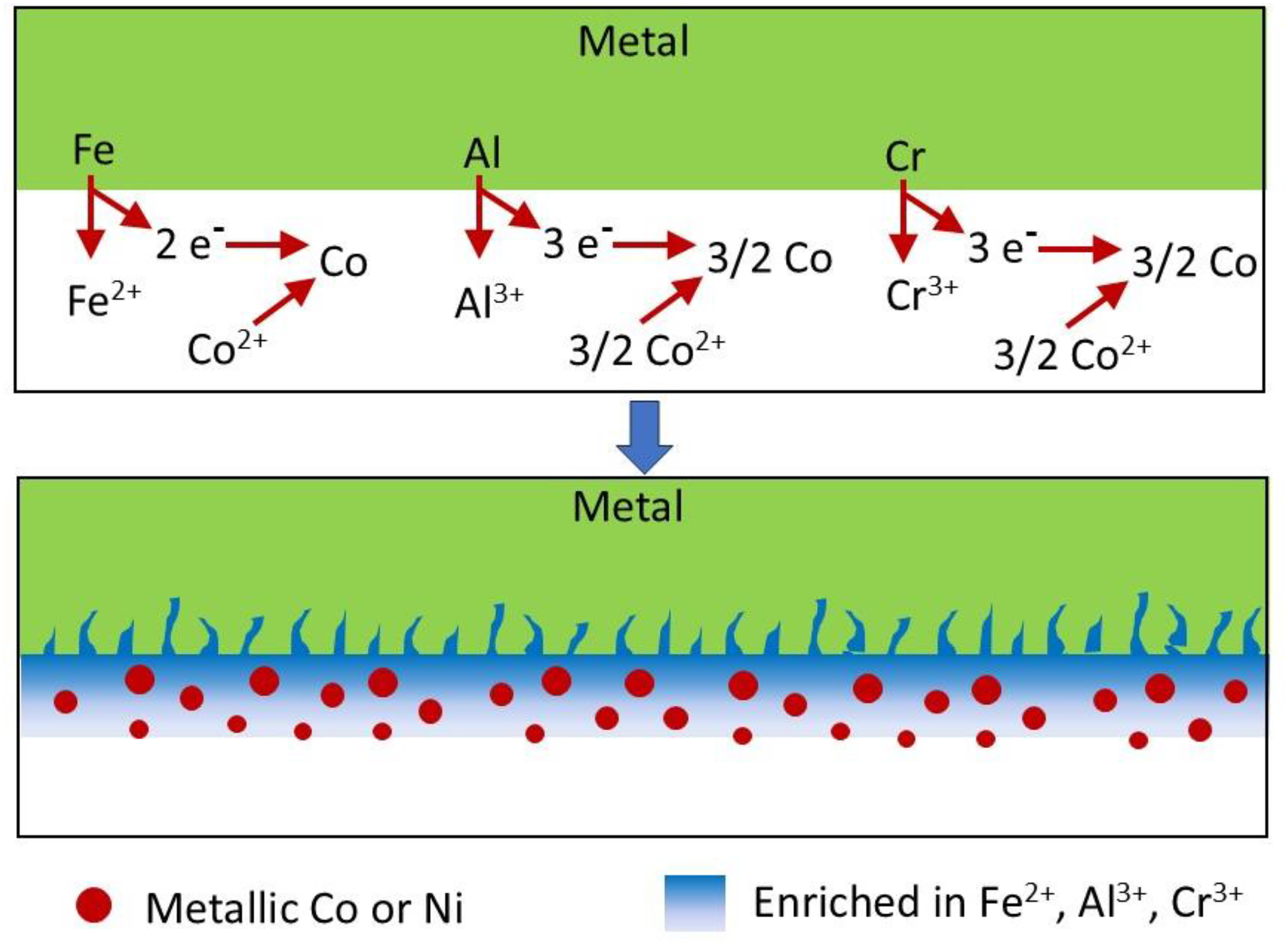
Schematic of the reactive glass seal. The least noble compounds of the metal are oxidised and cobalt or nickel oxides of the glass seal are reduced to the metal.
Figure 16 shows an SEM micrograph and some EDX mappings of a seal with the mol% composition 17 CoO·26 BaO·54 SiO2·B2O3·ZrO2·La2O3·sealed to the high temperature alloy NiCroFer™. The particles of bright appearance occurring in the glass seal are metallic cobalt. The dark appearing structures are enriched with oxides of aluminium, chromium and iron. In about 10 μm distance from the interface, crystals enriched in Ba, Co and Si are detected, which are attributed to BaCo2Si2O7, a phase with a CTE (100–900 °C) of 12.1·10−6 K−1 which is suitable to seal metals with high CTEs. In between, a glassy phase occurs enriched in La and Zr which are not incorporated in the crystal. The redox reaction leads to a strong interlocking of the seal and the metal which is highly advantageous for a strong adherence.
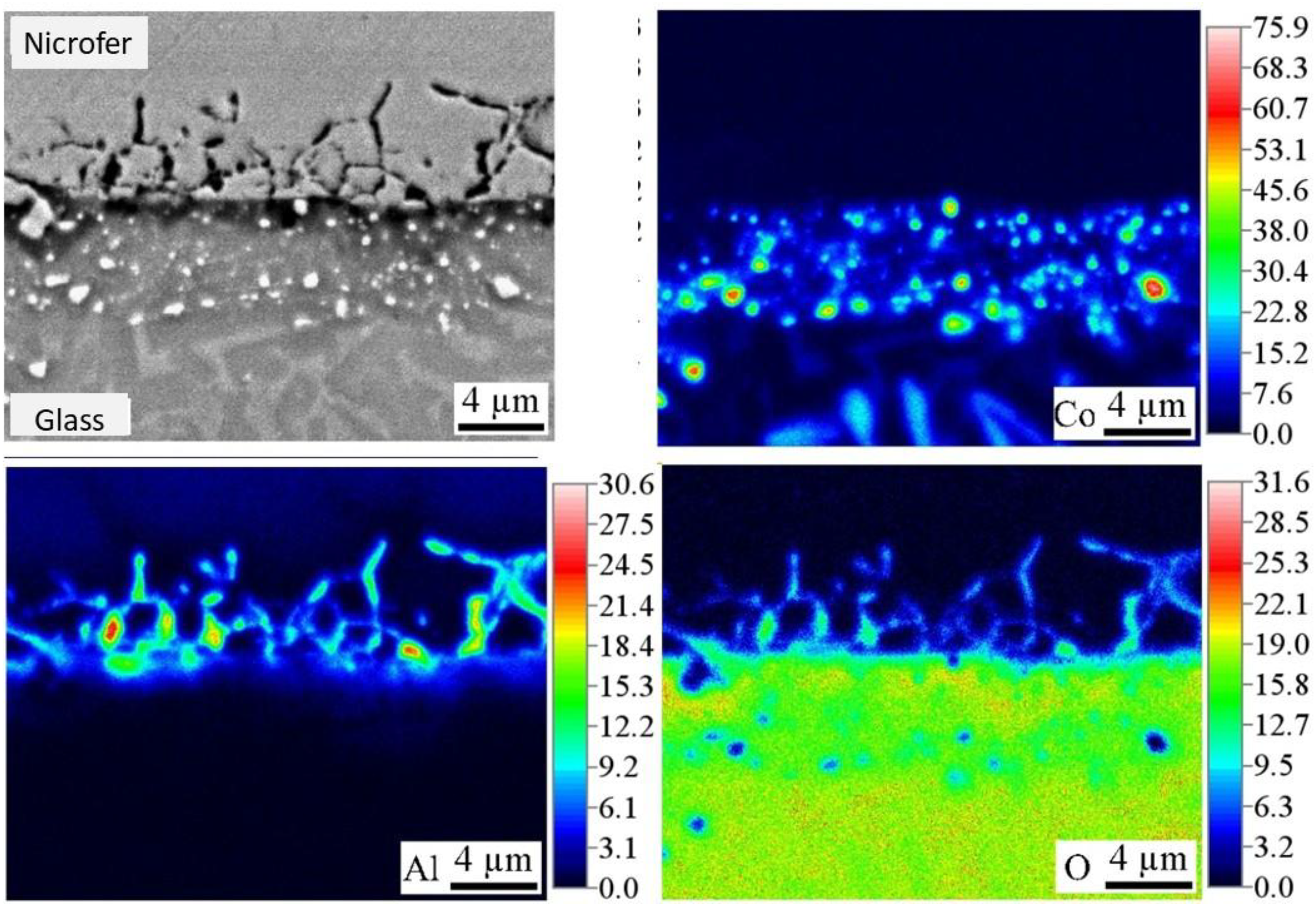
Crystallized glass seal adjacent to a NiCroFer™ alloy. Top left: SEM micrograph, Top right EDX map of Co. Bottom left: EDX map of Al. Bottom right: EDX map of O. Reprinted with permission from Ref. 7 from Springer Nature.
General rules for the tailoring of the chemical composition of crystallizing glass seals
Adjustment of the main components of a crystallizing glass seal
The main components of the glass seal should be chosen with respect to:
Sufficient chemical durability under the conditions of the respective application. That might be a strongly reducing or an oxidising atmosphere, the humidity or any other corrosive atmosphere or also chemical reactions with the sealed materials. The aimed crystalline phases formed during thermal treatment should possess suitable CTEs, however, also the CTE of the residual glass phase should be considered. The latter can be estimated using appropriate databases such as SciGlass
172
and simple mixing rules (see equation (13)). A mismatch in the CTEs > ± 1·10−6 K−1 should be avoided. It should be noted that the formation of stresses in glass-ceramics must be regarded as more critical than in non-crystallizing sealing glasses. This is due to the fact that glasses only build up stresses when they can no longer relax, i.e., when they reach the glass transition temperature, which is lower than the sealing temperature. Glass-ceramics can no longer relax the stresses starting at the crystallization temperature, assuming there is only little residual glass matrix. Therefore, after cooling to room temperature and with the same CTE difference between the joining partners, the resulting stresses using a glass-ceramic instead of a glass may be greater. The glass composition should possess a softening temperature which enables densification by sintering at appropriate temperatures, i.e., below that temperature, the materials to be sealed are damaged. The aimed volume concentration of crystallized phases strongly depends on the temperature during application. A high volume concentration (near 100%) has the advantage that further crystallization cannot take place and hence, if phase transitions during application temperature do not play any role, the CTE of the seal should not change during application. This can be achieved, e.g., by the crystallization of solid solutions such as melilite, which may incorporate all components of the glass composition. A notable quantity of glass phase, however, should offer the effect that “self-healing” of the sealing material may be possible due to viscous flow. This might be advantageous, if tiny cracks are formed, e.g., during temperature change. The disadvantage of the occurrence of a glassy phase is that further crystallization may occur during application which can result in the change of the CTE. For many applications, certain physical properties of the sealing material are necessary. As an example, in SOFCs but also in the field of semiconductors, certain electrical properties are also required. For this purpose, it is often necessary to prevent excessive diffusion between the materials to be joined and to achieve a low conductivity of the glass-ceramics. This is primarily achieved by excluding alkali oxides (Li2O, Na2O, K2O).
Addition of minor components
The addition of minor components is frequently necessary in order to control the crystallization behaviour and sometimes also to improve the adherence of the seal with the materials to be sealed. The minor components of a crystallizing glass seal should be chosen with respect to the following considerations:
The glass composition should not notably crystallize before densification is reached. The crystallization behaviour can be affected by the addition of nucleation agents or nucleation inhibitors as well as by the applied temperature/time schedule. Nucleation inhibitors decrease the nucleation rate at the same viscosity and increase the induction period of nucleation.6,218–222 For this purpose, comparatively small additions of 1–2 mol% of compounds such as ZrO2, TiO2, La2O3, Nb2O5 or Ta2O5 are sufficient. Nucleation agents, such as ZrO2 or TiO2 in most aluminosilicate glasses have to be added in much higher concentrations (4–9 mol%). These compounds (or compounds derived hereof) are precipitated just above Tg and then induce volume crystallization. Volume nucleation is highly advantageous for crystallizing glass seals for two reasons: the first is the statistical orientation of the crystal, which means that the seal should have the same CTE parallel and perpendicular to the sealed materials. The second reason is that if the glass grains should show high nucleation rates at the surface, sintering is much more difficult, because the glass grains are covered by the formed crystalline phase. Adherence to the materials to be sealed Many ceramic materials have good compatibility to the glass and show strong adherence. This might change during crystallization. Metals are often not as well wetted by the glass. This can notably be improved by a pre-oxidation of the metal, if it forms a well adherent oxide layer. Another possibility is to add small concentrations of easy to reduce metal oxides, such as CoO, NiO or CuO. If the metal to be sealed contains metallic components which are less noble than the above-mentioned ones, they undergo a redox reaction which results in the oxidation of the metal and the reduction of the glass components. This leads to an interlocking of the seal and the metal and hence to an increase in the adherence. There is not much literature in this field and it is not yet clear for which alloy the adherence can be improved.7,214,215,217
Conclusions
The chemical composition of a crystallizing glass seal has to be adjusted to the materials to be joined. Here, the coefficient of thermal expansion and the maximum operating temperature of the composite as well as the maximum allowed temperature for the sealing process are the most important boundary conditions. For many composites also some additional physical properties, such as mechanical or electrical ones are required.
For the preparation of crystallizing glass seals, first the main components of the glass should be chosen, especially with respect to the crystalline phases to be formed and their coefficient of thermal expansion.
To achieve the intended densification behaviour, the viscosity of the glass has to be adjusted to enable sintering and complete densification at temperatures low enough to avoid damage of the materials to be joined. A necessary decrease in the sealing temperature can, e.g., be achieved by the addition of minor quantities of B2O3 or fluoride. The densification behaviour is also affected by the crystallization behaviour. Here, densification at the respective temperature should be achieved before the major part of the glass is crystallized. In many cases, the crystallization behaviour can be tailored by the addition of minor concentrations of nucleation agents or nucleation inhibitors.
The adherence of a crystallizing glass seal to some metal alloys can be promoted by the addition of minor concentrations of oxides which lead to an oxidation of the metal to be sealed, while the added oxide is reduced to the metallic state. This leads to mechanical interlocking of the metal and the seal.
At operating temperatures, the crystallization process should not further proceed in such an extent that the coefficient of thermal expansion changes notably and the mismatch in the coefficient of thermal expansion gets too large.
Footnotes

Funding
The authors received no financial support for the research, authorship, and/or publication of this article.
Declaration of conflicting interests
The authors declared no potential conflicts of interest with respect to the research, authorship, and/or publication of this article.