
Abstract
Effects of microscale poly-p-oxybenzoate (trade name Ekonol), nanoscale carbon nanotubes (CNTs) and multiscale fillers on the mechanical, creep and tribological properties of polytetrafluoroethylene (PTFE) are studied. Results reveal that the multiscale PTFE composite with 20 wt% Ekonol and 1 wt% CNTs has the highest tensile strength and modulus as well as relatively modest elongation at break compared to pure PTFE, micro and nanoscale PTFE composites. In addition, the combination of Ekonol and CNT fillers leads to a significant improvement in creep resistance of PTFE composites. Scanning electron microscopic observation of tensile fracture surfaces indicates that for multiscale composite, the surfaces of Ekonol particles are wrapped by individual CNTs and the bridge of CNTs between Ekonol particles is formed. Also, the combination of Ekonol and CNT fillers slightly increases the friction coefficient of multiscale composite but greatly decreases the wear rate by approximately four orders of magnitude compared with pure PTFE. Scanning electron microscopic observation of the worn surfaces shows that the wear surface of the multiscale composite is very smooth. Therefore, the wear resistance significantly improved. The synergetic role of multiscale fillers is expected to open up new opportunities to formulate high-performance PTFE composites.
Introduction
Polytetrafluoroethylene (PTFE) is widely used in industries as antifrictional wear-resistant material, owing to the unique combination of the service properties, in particular self-lubricating capacity, low outgassing, high chemical inertness and high temperature capability. 1,2 However, high creep and wear rate as well as low mechanical property of the virgin PTFE restrict its use in loaded friction units and induce the development of PTFE-based composites with high creep resistance under stress, high wear resistance and high mechanical property.
Earlier studies showed that the filling of some inorganic particles and fibers, such as graphite, bronze, molybdenum disulfide, glass and carbon fibers, 3 led to significant improvement in the wear rate of PTFE composites and caused the abrasive properties that reduced the life of precise friction units. This induced the development of special grades of PTFE composites filled with powders or fibers of thermally stable polymers, such as aromatic polyamides, 4 polyimides (PIs), polyphenylene sulfides, polyetheretherketones (PEEKs), 5 poly-p-benzoate 6 and so on. In the past few years, some nanofillers, such as ZnO, 7 carbon black, 8 aluminum oxide (Al2O3) 9 and so on, have been incorporated into the PTFE matrix to improve the wear resistance of PTFE by three orders of magnitude, but low-loading nanoparticles-filled composites lack the favorable mechanical property, high creep resistance and relatively high wear resistance.
Poly-p-oxybenzoate (trade name Ekonol), similar to PTFE, has low friction coefficient and creep, high-temperature stability and low wear rate, 10 which makes it suitable to be added into the PTFE matrix, so that Ekonol/PTFE composites take advantage of high wear and creep resistance of Ekonol as well as very low friction coefficient of PTFE. Nevertheless, owing to weak interfacial forces between Ekonol particles and PTFE matrix, the incorporation of Ekonol into the matrix usually deteriorates mechanical properties of the matrix. So, it is a continually challenging task for polymer scientists and engineers to improve the tribological properties and creep resistance of PTFE simultaneously with the mechanical properties, for example, stiffness and strength. Carbon nanotubes (CNTs) are considered as ideal reinforcing agents to produce high-performance composites because they possess superior mechanical properties (Young’s modulus: 1 TPa; bending strength: 14.2 GPa), high aspect ratio (>1000), high electrical conductivity and thermal conductivity. 11 –14 Therefore, the addition of CNTs into Ekonol–PTFE blends is highly expected to improve simultaneously mechanical, creep and tribological properties of the composites. To the best of our knowledge, this work has not been reported.
The aim of the study is to investigate the effect of microscale Ekonol, nanoscale CNTs and multiscale fillers on the mechanical, creep and tribological properties of PTFE composites, respectively.
Experimental details
Materials
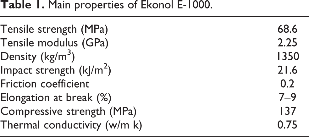
PTFE powder (M-18F, Daikin, Osaka, Japan) with an average particle size of approximately 25 μm purchased from Shanghai Materials Institute was used as the matrix resin for the composites. Ekonol resin powder (E1000, Sumitomo Chemical Co., Ltd, Tokyo, Japan) with an average particle size of approximately 10 μm was used as reinforcement. Its properties are given in Table 1. Another reinforcement used in the present study was the multiwalled CNTs (MWCNTs) produced by Chengdu Organic Chemicals Co. Ltd (Chengdu, China). The MWCNTs have the following specified properties: purity, >95%; outer diameter, 30–40 nm; length, 0.5–50 μm and specific surface area, 40–1000 m2/g. Ethanol without water was used as a solvent.
Main properties of Ekonol E-1000.
Sample preparation
Three series of PTFE composites, that is, microcomposites filled with Ekonol, low-loading nanoparticles-filled nanocomposites and multiscale composites reinforced with both Ekonol and low-loading nanoparticles, were compared in this study. The loading of the CNT nanoparticles varied from 0.1 wt% to 2.0 wt%. Pure PTFE and Ekonol-filled PTFE (with Ekonol fractions from 10 wt% to 30 wt%) served as reference materials.
MWCNTs were stirred into the mixture of concentrated nitric acid and sulfuric acid with a volumetric ratio of 1:3. The weight ratio of MWCNTs and mixed acid was 1:400. The above MWCNTs mixture was boiled at 80°C for 2 h by stirring at 300 r/min. After cooling this mixture to room temperature, it was diluted with deionized water and then vacuum filtered through 0.22 μm millipore PTFE membranes and washed with an excess of distilled water until the pH value of the filtrate reached approximately 7. The filtrated solid was dried under vacuum at 100°C for 10 h. After pretreatment of MWCNTs, appropriate masses of MWCNTs (0 wt%, 0.1 wt%, 0.5 wt%, 1 wt% and 2 wt% MWCNTs) and Ekonol-PTFE powder (0 wt%, 10 wt%, 20 wt% and 30 wt% Ekonol) were combined to achieve micro, nano and multiscale MWCNTs-Ekonol-PTFE mixtures, respectively. The detailed compositions of the materials are disclosed in Table 2. The powder ensembles were combined with ethanol, mechanically stirred at high speed for 10 min and subsequently ultrasonically dispersed for 1 h. Then, the suspensions were heated to 100°C in a vacuum oven for 3 h to remove the ethanol and then further dried under vacuum for 10 h at 80°C to obtain solid powder mixtures. Following dispersion and drying, the dried powder was compression molded at 380°C under a pressure of 60 MPa for 2 h and then machined into test specimens.
Compositions of materials studied.
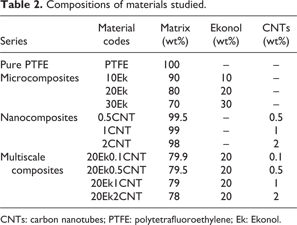
CNTs: carbon nanotubes; PTFE: polytetrafluoroethylene; Ek: Ekonol.
Tensile test
Tensile tests were performed at room temperature (25°C) on a Zwick E (Zwick, Ulm, Germany) universal testing machine at a constant crosshead speed of 5 mm/min. The measurements followed the Chinese standard GB/T 1040-2006 using dumbbell-shaped specimens. The specimens with 4 mm thickness were machined from the molded plates. The overall length of dumbbell-shaped specimens is 170 mm. The length and width of narrow section are 50 mm and 10 mm, respectively. All presented data correspond to the average of at least five measurements.
Creep test
The creep property of materials, to some extent, can be reflected by indentation creep. 15 So, the experiment tested the indentation creep property of PTFE composites. The indentation creep tests were performed using an UMT-2 tribometer (Center for Tribology Inc., Campbell, California, USA). The indenter comprised a GCr15 steel ball and the diameter of the ball is 4 mm. The constant load applied to the sample was 132 N for a period of 30 min. In the process of ball indentation, when the load increased to 132 N, the indentation depth was set as zero and the depth was noted. All presented depth data correspond to the average of at least five measurements.
Tribological test
The tribological property of the composites was evaluated on a ball-on-block reciprocating UMT-2 tribometer at room temperature with a relative humidity of 50%. Figure 1 is the sketch of the friction pair (UMT-2; Center for Tribology Inc.). The wear loss of the specimen was measured using the electronic balance (accuracy: 0.1 mg; China). The specific wear rate, K (mm3/Nm), of the composite was calculated using the equation K = M/(gLF), where M is the wear mass in gram, g is the density of the composites in gram per cubic millimeter, L is the total sliding distance in meter and F is the applied load in Newton. The specimens were polished using a fine grade SiC emery paper, cleaned ultrasonically with acetone and dried before testing. The reciprocating friction stroke was 5 mm and tests were conducted at a normal load of 15 N with a reciprocating frequency of 10 Hz. The friction time was 60 min. The counterpart (ball of 3 mm in diameter) was made up of GCr15. The hardness of the counterface was HRC 45 and the surface roughness was 0.1 μm. Five identical specimens were obtained to conduct tribological tests under the same testing conditions. Average values of measured friction coefficient and wear loss were used for further analysis.
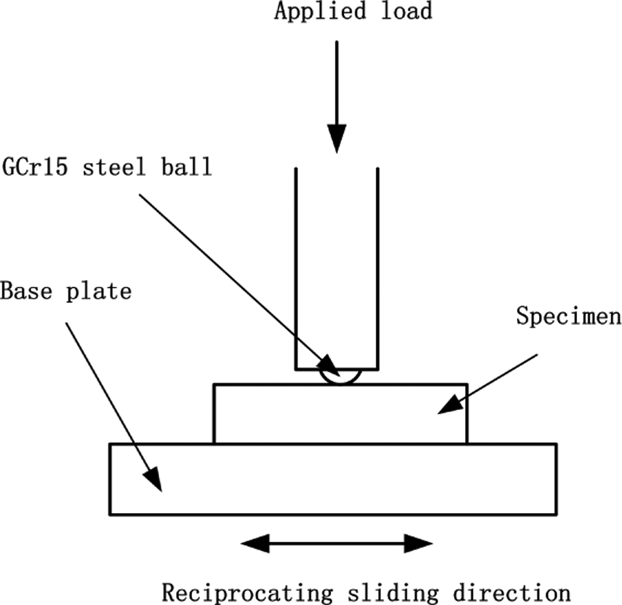
Sketch of the friction pair for the reciprocating sliding contact.
The fracture surfaces of the composites were observed by a scanning electron microscope (SEM, S-3400 N, Hitachi, Tokyo, Japan). The morphology of the wear surface of the specimens was observed using a SEM (Quanta 200 FEG, FEI, Eindhoven, The Netherlands). The specimen surfaces were coated with gold before observation. The transfer films on the counterfaces were observed using an optical microscope (OM VHX-2000, Keyence, Osaka, Japan).
Results and discussion
Tensile properties
Figure 2(a) to (c) shows the mean values of tensile strengths, tensile moduli and elongations at break of the material studied, respectively. With respect to Ekonol/PTFE microcomposites, the tensile strength and elongation at break of Ekonol-filled PTFE composites decrease linearly with Ekonol varying from 10 wt% to 30 wt%, as shown in Figure 2(a) and (c). The tensile strength decreases from 31.29 MPa for pure PTFE to 22.61 MPa for 30 wt% Ekonol/PTFE microcomposites. The elongation at break is reduced from 301% for pure PTFE to 221% for 30 wt% Ekonol/PTFE microcomposite. However, the tensile modulus of Ekonol/PTFE microcomposites increases monotonously from 209 MPa for pure PTFE to 342 MPa for 30 wt% Ekonol/PTFE microcomposite with increasing Ekonol content. The decrease in tensile strength is due to the low surface energy and nonpolarity of PTFE as well as weak interfacial bonding between PTFE matrix and Ekonol fillers, which cannot efficiently transfer the stress from PTFE matrix to filler. 16 The reduction in elongation at break is attributed to the presence of brittle Ekonol that may interrupt the continuity of the molecular chains of PTFE and cause stress concentration in the region close to Ekonol particles, resulting in the earlier fracture of PTFE microcomposites after the Ekonol particles were incorporated into the PTFE matrix.
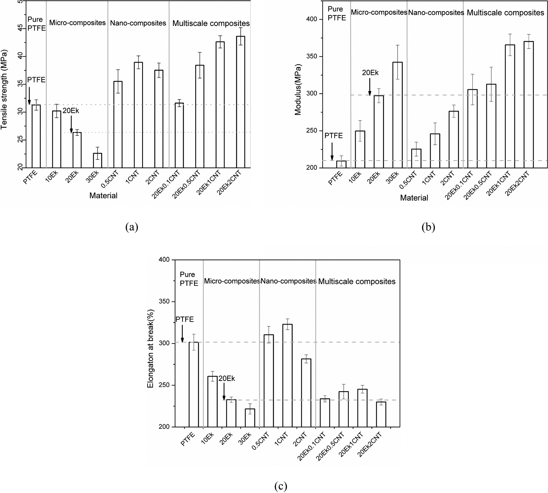
The tensile characteristics: tensile strength (a), E-modulus (b) and elongation at break (c) of PTFE composites. Dashed lines in (a)–(c) indicating the levels of two reference materials, that is, pure PTFE and Ekonol/PTFE, are added for easier comparisons. PTFE: polytetrafluoroethylene.
The tensile strength of CNTs/PTFE nanocomposites is significantly increased from 31 MPa (pure PTFE) to 39 MPa (1 wt% CNTs) with CNTs varying from 0.5 wt% to 1 wt%. (compare Figure 2(a)). A further increase in the CNTs loading to 2 wt% leads to a slight decrease in tensile strength. The enhancement in tensile strength of CNTs/PTFE nanocomposites is due to the large specific surface of CNTs, a certain amount of reactive functional groups (like hydroxyl and carboxyl) on CNT surfaces after mixed acids pretreatment and relatively uniform dispersion of CNTs in the PTFE matrix. Vail et al. 17 investigated the tensile strength of single-walled CNTs-PTFE (SWCNTs-PTFE) composites and concluded that 2 wt% SWCNTs produced the maximum tensile stress, which is 50% higher than that of pure PTFE. This reinforcing effect of SWCNTs on tensile strength is consistent with that of our MWCNTs. Similar reinforcing effects of CNTs-based composite materials with various matrices, 18 –25 such as PI, 26 PEEK, 27 polycarbonate 28 and polystyrene, 29 have been reported.
The low-loading CNTs lead to a significant and monotonous increase in modulus (compare Figure 2(b)). This is because CNTs have much higher tensile modulus than PTFE polymer. With a CNTs loading less than 1 wt%, the elongation at break is slightly increased due to the excellent interfacial adhesion between CNTs and PTFE. This result agrees well with the literature reported by Vail et al. 17 Filled with 2 wt% CNTs, however, the CNTs/PTFE nanocomposite exhibits a reduced ductility (compare Figure 2(c)). This may be caused by the aggregation of CNTs.
The combination of microfillers and nanofillers leads to impressive improvements in strength and modulus data of the PTFE (compare Figure 2(a) and (b)). The strength and modulus of the multiscale composites increase with increasing CNTs content. Note that among the systems studied, application of multiscale fillers was the only way to achieve simultaneous improvements in strength and modulus.
In addition, it is interesting to note that the enhancements in strength and modulus owing to the multiscale fillers are significantly higher than the superposition of the separate contributions by respective fillers, as realized in the Ekonol-filled and the CNTs-filled PTFE (compare Figure 2(a) and (b)). Therefore, the multiscale fillers have synergistic effects on the stiffness and strength of the PTFE matrix. The elongations at break of the multiscale composites are similar to that of the composite filled only with 20 Ekonol (Ek) (compare Figure 2(c)). The great enhancement in strength of multiscale composites compared to 20Ek microcomposite and pure PTFE is due to the following three aspects. First, uniform and functionalized CNTs, as shown in Figure 3 (CNTs 1), can improve the tensile strength of multiscale composites, as realized in CNTs-filled PTFE nanocomposites. Second, on the one hand, some CNTs wrap the surfaces of Ekonol particles and may form strong π–π interaction 30 –35 with Ekonol molecular chains, as shown in Figure 3 (CNTs 2). On the other hand, the CNTs wrapping the surfaces of Ekonol particles will form relatively strong interfacial adhesion with PTFE matrix through reactive functional groups of CNTs (e.g. hydroxyl and carboxyl). So, the interfacial adhesion between Ekonol particles and PTFE matrix in the presence of CNTs is greatly improved. Third, as shown in Figure 3 (CNTs 3), two ends of individual CNTs are, respectively, wrapping two separate Ekonol particles. When the composites are subjected to tensile stress, two ends of CNTs seem to be anchored in the Ekonol particles, which would greatly reduce the chance of pullout of CNTs from the PTFE matrix. This bridging of CNTs between two Ekonol particles may be the main reason for synergistically improved stiffness and strength of multiscale composites.
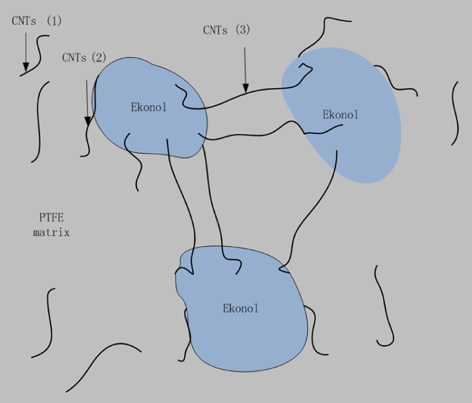
Schematic diagram of CNTs distribution in Ekonol-PTFE multiscale composites. CNTs: carbon nanotubes; PTFE: polytetrafluoroethylene.
Morphologies of fracture surfaces
Figure 4 indicates the scanning electron micrographs of cryogenic fracture surfaces of PTFE and PTFE composites. As shown in Figure 4(a), it can be seen that numerous resin residuals deformed plastically and dimples appear on the PTFE fracture surface. This is due to the large ductility of PTFE and unrecoverable plastic deformation of PTFE matrix when fractured. Figure 4(b) shows a typical scanning electron micrograph of the fracture surface of CNTs/PTFE nanocomposites with 1 wt% CNTs. It can be found that uniform and individual CNTs are distributed in the fracture surface, which is the key issue for CNTs to greatly improve the tensile strength of CNTs/PTFE nanocomposites. Figure 4(c) and (d) presents the scanning electron micrographs of the fracture surface of the CNTs/Ekonol/PTFE multiscale composite (1 wt% CNTs) with low and high magnifications, respectively. It can be observed from Figure 4(c) that the Ekonol particles wrapped by CNTs are fixed in the PTFE matrix and some CNTs on the surfaces of Ekonol particles bridge the gap between the neighboring Ekonol particles while other CNTs bridge between the Ekonol particles and PTFE matrix. It is clear in Figure 4(d) that some parts of CNTs are wrapping tightly the surfaces of Ekonol particles, while the rest parts of CNTs connect tightly with the PTFE matrix. These two images further confirm that the bridging of CNTs at the interfaces between Ekonol and PTFE is the main mechanism for the great improvements in strength and modulus of the CNTs-Ekonol-PTFE multiscale composite.
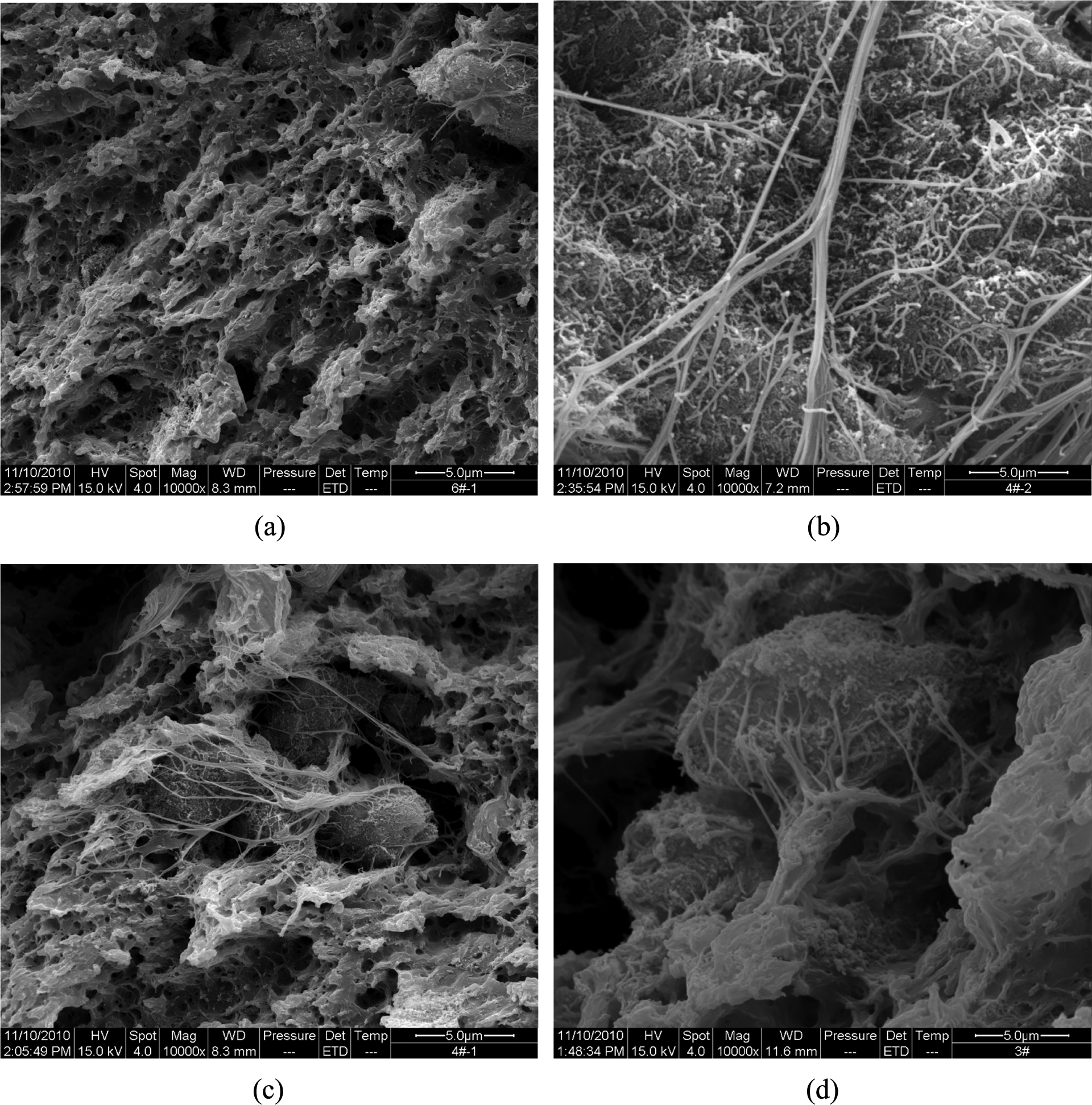
Typical scanning electron micrographs of (a) PTFE; (b) CNTs/PTFE composite; (c and d) CNTs/Ekonol/PTFE with low and high magnifications, respectively. CNTs: carbon nanotubes; PTFE: polytetrafluoroethylene.
Creep property
Figure 5 shows the results of typical creep curves of PTFE and PTFE composites. It can be seen that the indentation depth of various materials is increased quickly in the first 800s of the test and then increased slowly. As shown in Figure 6, it is obvious that pure PTFE has the highest creep depth, while the multiscale composite containing 1 wt% CNTs has the lowest creep depth, as much as half creep depth of pure PTFE. This is attributed to the high hardness and creep resistance of Ekonol particles compared to PTFE matrix as well as the distribution of CNTs in the Ekonol/PTFE compounds mentioned above. A similar result has been reported elsewhere for CNTs-reinforced ultrahigh-molecular-weight polyethylene (UHMWPE) and high-density polyethylene blends. 36 In addition, the Ekonol/PTFE microcomposites have better creep resistance than CNTs/PTFE nanocomposites. This may be caused by the differences of grain size and content of the two kinds of reinforcements.
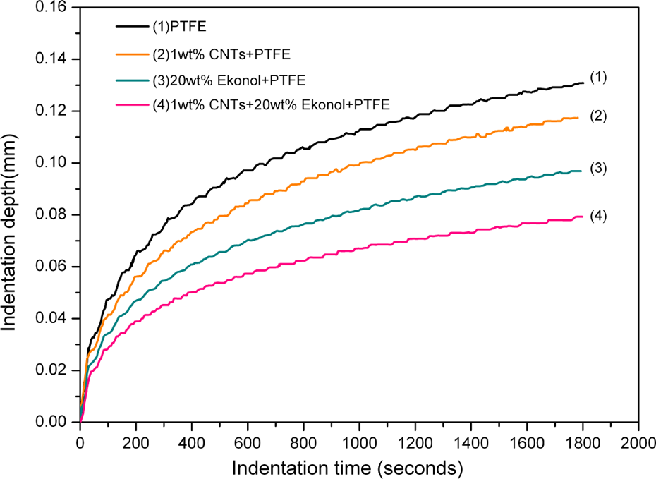
Typical creep curves of different sample materials with indentation time.
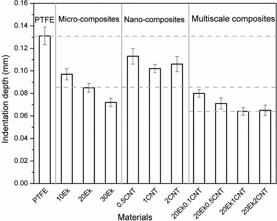
Indentation depths after 30 min for all materials tested.
Friction and wear properties of PTFE composites
Figure 7 shows the friction coefficient values of various materials tested. It can be seen that pure PTFE has the lowest friction coefficient (0.14). The addition of Ekonol and CNTs into the PTFE matrix leads to the increase in friction coefficient with increasing filler loading, respectively. This is due to the fact that the hard Ekonol and CNTs easily damage the transfer film formed on the counterfaces and thus delay the formation of uniform transfer film. However, for multiscale PTFE composites, the incorporation of Ekonol and CNTs into the matrix results in a slight reduction in friction coefficient compared to 20Ek composite. This indicates that CNTs can reduce the damage caused by Ekonol to the transfer film to some extent. So, the multiscale composite has better friction-reducing property than micro and nanocomposites.
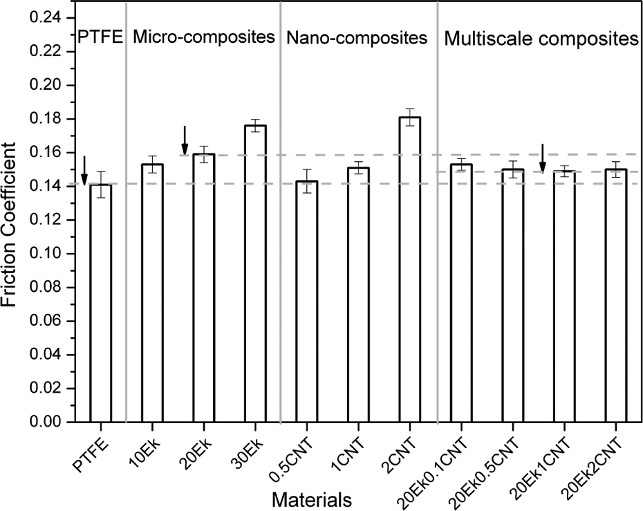
Friction coefficient values of various materials tested.
Results of the wear tests for various materials are shown in Figure 8. It can be seen that pure PTFE has the highest specific wear rate with about 5 × 10⁻⁴ mm3/(Nm). For microcomposites, the specific wear rate first decreases markedly and then increases slightly with Ekonol filler loading ranging from 10 wt% to 30 wt%. At 20 wt% Ekonol, the Ekonol/PTFE composite has the minimum specific wear rate, approximately 1 × 10⁻⁶ mm3/(Nm), which is only 1/500 that of pure PTFE. This result is attributed to the presence of Ekonol. On the one hand, Ekonol is much harder with higher wear resistance than PTFE, sliding against the counterpart. On the other hand, Ekonol particles in the PTFE matrix could support most of the loadings applied to the contact surface of Ekonol/PTFE composites and prevent the PTFE detaching in large scale from the matrix. The improvement in wear resistance of the Ekonol/PTFE composite is similar to that of the Al2O3/PTFE composite reported by Sawyer et al. 37 For nanocomposite, the specific wear rate of CNTs-filled PTFE decreases monotonically with CNTs filler loading ranging from 0.5 wt% to 2 wt%, indicating high wear resistance. Similar wear resistance of the CNTs/PTFE composite was described by Chen et al. 38 The combination of Ekonol and CNTs leads to a further decrease in the wear rate of the Ekonol/CNTs/PTFE composite with increasing CNTs loading compared to the 20Ek composite, and then results in a slight increase in the wear rate with an increase in CNTs loading of up to 2 wt%. At 1 wt% CNTs, the multiscale composite has the lowest specific wear rate, 2 × 10⁻⁷ mm3/(Nm), one-fifths that of the 20Ek composite. The further improvement in the wear rate of multiscale composites may be caused by the synergistic effect of Ekonol and CNTs aforementioned.
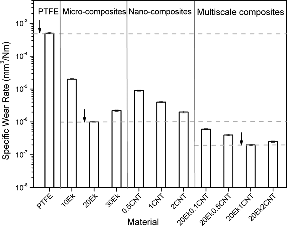
Specific wear rate values for various materials tested.
Scanning electron microscopic observation of worn surfaces and transfer films on the counterfaces
Figure 9 shows the typical scanning electron micrographs of worn surfaces of PTFE and PTFE composites with fillers in different scales. As shown in Figure 9(a), severe delamination, peeling and some pits can be found on the wear surface of pure PTFE, which is indicative of the adhesive wear mechanism. This is due to the fact that a PTFE crystal has a ribbon-like structure and smooth surface, which makes the PTFE crystal detach from the matrix so as to leave some pits when subjected to friction force, 38 and thus results in high wear loss. It can be seen from Figure 9(b) that Ekonol particles are uniformly distributed in the PTFE matrix, and the wear surface is smooth, but some cracks are visible in the interphases between Ekonol particles and PTFE matrix, which is due to the weak interfacial adhesion between Ekonol and PTFE along with stress concentration in the sliding process. So fatigue wear is the main wear mechanism for the sliding of the Ekonol/PTFE composite against a hard counterpart. Although smooth wear surface is favorable for the improvement in the wear rate of the Ekonol/PTFE composite, the microcracks would lead to more serious stress concentration and thus debris might be generated at the edge of microcracks, which would greatly increase the wear rate of PTFE composites.
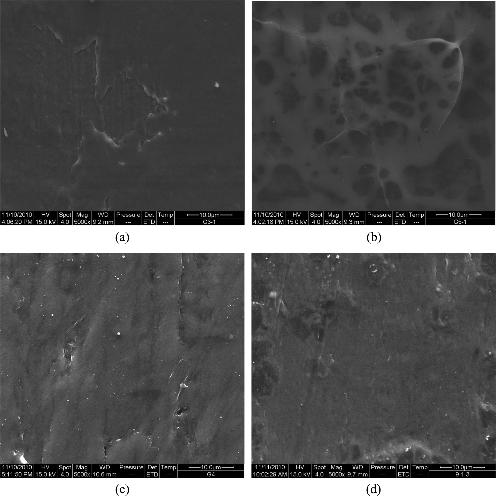
The typical scanning electron micrographs of worn surfaces of PTFE composites containing: (a) 0 wt% filler, (b) 20 wt% Ekonol, (c) 1 wt% CNTs and (d) 20 wt% Ekonol + 1 wt% CNTs. CNTs: carbon nanotubes; PTFE: polytetrafluoroethylene.
It can be observed from Figure 9(c) that many tips of CNTs are uniformly sticking out of the worn surface of nanocomposite with 1 wt% CNTs, and few CNTs entangled with PTFE matrix lie at the worn surface. This distribution of CNTs in PTFE helps to sustain partly the normal load, anchor PTFE macromolecular chains, and thus prevent macromolecular chains from detaching from the PTFE matrix, leading to a sharp decrease in the wear rate. So, the adhesive wear of CNTs-filled nanocomposites reduced significantly compared to PTFE. This result is consistent with the literature reported by Chen et al. 38
In Figure 9(d), the wear surface of the multiscale composite with 20 wt% Ekonol and 1 wt% CNTs is very smooth and has no visible cracks, indicating excellent wear resistance.
Figure 10 shows the typical OM images of transfer films on the counterfaces sliding against PTFE and PTFE composites. It can be seen in Figure 10(a) that the observed counterface is completely covered with thick transfer film of PTFE, indicating high wear rate of the PTFE matrix. Figure 10(b) reveals that thin and ribbon-like transfer film is visible on the counterface sliding against Ekonol/PTFE microcomposites, which indicates that hard Ekonol particles or microcracks probably abraded some formed transfer films away. Figure 10(c) shows that some microploughings appear in the thin transfer film on the counterface sliding against CNTs/PTFE nanocomposites, indicating that tips of CNTs sticking out of the worn surface probably caused the microploughings and thus increased the friction coefficient. It can be observed from Figure 10(d) that thin and uniform transfer film appears on the counterface sliding against the Ekonol/CNTs/PTFE composite, indicating the best tribological property of the multiscale composite compared with PTFE and other PTFE composites.
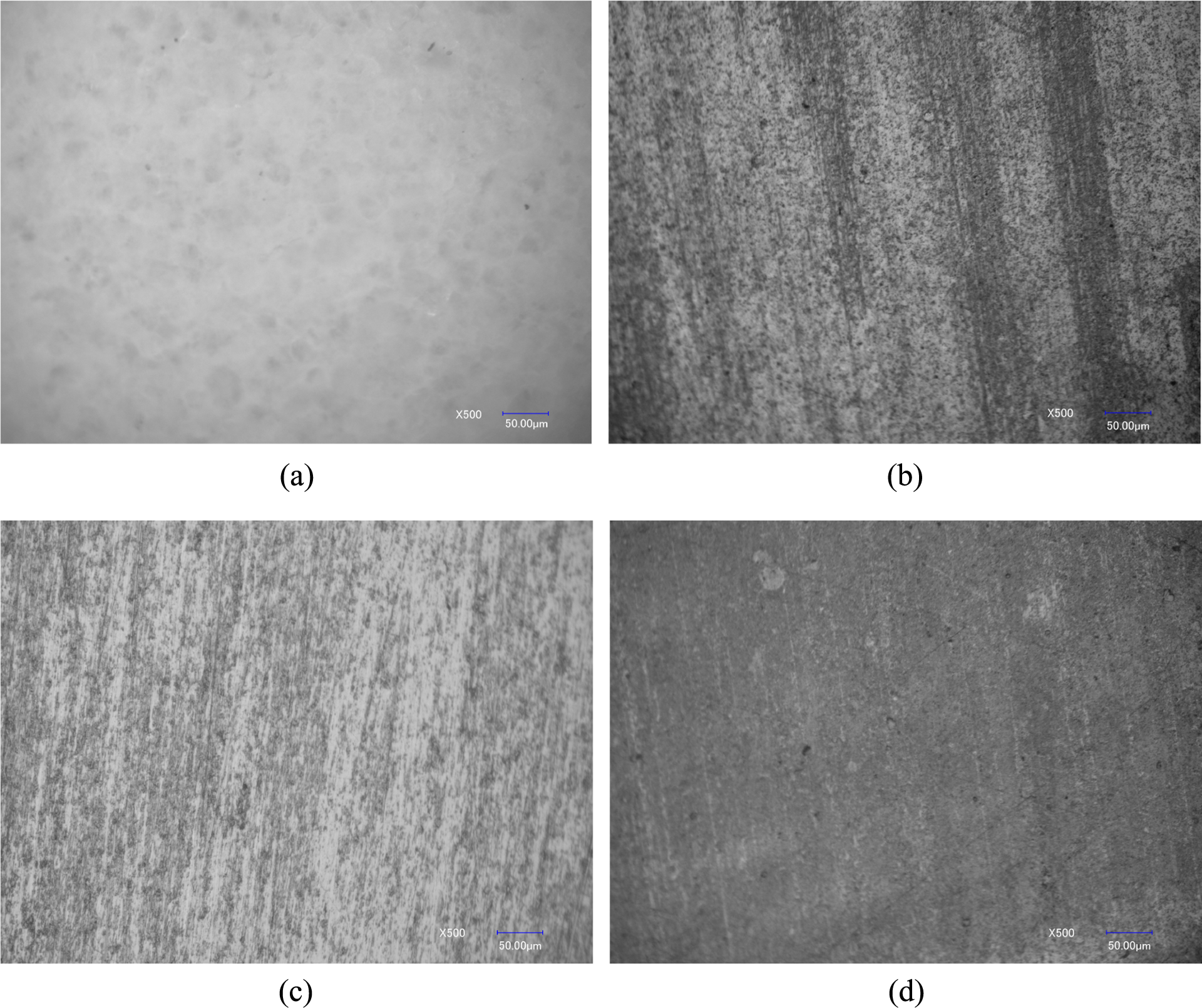
The typical OM images of transfer films on the counterfaces sliding against: PTFE composites with (a) 0 wt% filler, (b) 20 wt% Ekonol, (c) 1 wt% CNTs and (d) 20 wt% Ekonol + 1 wt% CNTs. CNTs: carbon nanotubes; PTFE: polytetrafluoroethylene.
Conclusions
In this study, the PTFE composites filled with microscale Ekonol, nanoscale CNTs and multiscale fillers were prepared by solution mixing and compression molding technique, respectively. The mechanical, creep and tribological properties of three series of composites were investigated. The results show that multiscale composite with 20 wt% Ekonol and 1 wt% CNTs has superior tensile strength, modulus and creep resistance to PTFE, micro and nanoscale PTFE composites. Furthermore, the combination of Ekonol and CNTs fillers slightly increases the friction coefficient of multiscale composites but significantly decreases the wear rate by four orders of magnitude. Therefore, the tribological properties of multiscale composites were improved markedly.
Footnotes
Acknowledgements
Sincere thanks go to anonymous reviewers for their valuable comments and good suggestions to improve this article.
Funding
This work was supported by the Free Exploration Project from Traction Power State Key Laboratory of Southwest Jiao Tong University of China (Grant no. 2009TPL-T12) and the Mechanical Engineering School Fund of Nantong University (Grant no. J2011005).