
Abstract
A proton-conducting film of gel polymer electrolyte, poly(vinylidene fluoride hexafluoropropylene)/poly(methyl methacrylate) + ammonium thiocyanate + ethylene carbonate + propylene carbonate, has been prepared by solution casting technique. The ionic conductivity of the film is in the order of approximately 10−3 S cm− 1 at room temperature. A proton battery with the configuration zinc + zinc sulfate heptahydrate | gel electrolyte | lead oxide + vanadium pentoxide has been fabricated using this film as electrolyte and separator between the electrodes. The battery shows an open circuit voltage of 1.45 V and energy density of approximately 10 Wh kg−1at low current drain. The rechargeability of the battery has been observed up to three cycles after which its discharge capacity starts fading.
Introduction
In recent years, portable applications of batteries have tremendously increased. Use of solid electrolytes as electrode separators in batteries gives opportunity for fabricating compact, safe, and stable cells of lesser weight, free of leakage and corrosion, and longer life in contrast with the liquid electrolyte (LE)-based cells. Currently, lithium (Li) ion batteries have attracted major attention because of higher energy densities of the cells. However, high cost and safety issues associated with Li batteries particularly related to the highly reactive Li+ ions have turned the attention toward other options beyond Li ion-based batteries like sodium ion, magnesium ion, and so on. Proton batteries (hydrogen (H+) ion batteries) may be considered yet another potential option because of good battery chemistry, low cost of the electrode and electrolyte materials, and no associated safety issues. The small ionic radii of H+ ions, like Li+ ions, makes it suitable for better intercalation into the layered structure of cathode, which is the preliminary requirement for a rechargeable battery. In the past, different inorganic compounds having fast proton conduction like hydrogen uranyl phosphate, 1 phosphotungstic acid, 2 phosphotungstic acid–phosphomolybdic acid composite, 3 and ammonium zinc sulfate 4 have been used to fabricate solid-state proton batteries. These proton conductors were used in the form of pallets within the electrodes to fabricate the battery. Recently, polymer electrolytes have been extensively studied because of their potential applications in various electrochemical devices such as fuel cells and supercapacitors. Flexibility, moldability, and large thermal expansion are some of the intrinsic properties of polymer electrolyte films, which make them attractive for device applications. Ali et al. 5 have reported a proton battery with polyethylene oxide (PEO)–ammonium sulfate ((NH4)2SO4) electrolyte system with zinc (Zn) as anode and lead oxide (PbO2), vanadium pentoxide (V2O5), and manganese dioxide as cathodes. The conductivity of the electrolyte, PEO-((NH4)2SO4), was approximately 10− 6 S cm− 1. Proton batteries with few plasticized polymer electrolytes having conductivity approximately in the range of 10−5–10−3 S cm−1 have also been reported in the previous literatures. 6 –9 According to Kadir et al., 8 the highly plasticized chitosan–poly(vinyl alcohol) blend-based proton battery was found to possess comparatively good power density of 9.47 mW cm−2 and rechargeability. It is known that for better battery performance, electrolyte must have high ionic conductivity and good compatibility with the electrodes. In this regard, gel electrolyte membranes may be an excellent substitute for the other electrolytes. Poly(vinylidene fluoride hexafluoropropylene) (PVdF-HFP) is a semicrystalline polymer and possesses a solid porous network, which can contain LE. Several such gel polymer electrolytes (GPEs) have been studied using PVdF-HFP as a host polymer immobilized with ionic liquids or LEs obtained by dissolving salts in polar liquids. These electrolytes have been found to show very high ionic conductivity however they suffer from leakage of LE from the porous network. Polymer blending, which is achieved by physically mixing two or more polymers, has the capability of tailoring various properties such as glass transition temperature (T g), melting point, and mechanical strength by suitably choosing the participating polymers.
In this article, we have reported a GPE system consisting of a blend of poly(methyl methacrylate) (PMMA)/PVdF-HFP as host polymer and a mixture of ammonium thiocyanate (NH4SCN) in ethylene carbonate (EC):propylene carbonate (PC) as LE. GPE membranes with various compositions of blend polymers have been prepared by solution casting technique for the purpose of finding optimum composition that shows maximum ionic conductivity. The optimized composition of the prepared GPE system is then used as a proton-conducting membrane and a separator in the proton battery with Zn/zinc sulfate heptahydrate (ZnSO4·7H2O) and PbO2/V2O5 electrode assembly. The performance of the battery has been assessed by measuring open circuit voltage (OCV), discharge characteristics, and rechargeability.
Experimental
Materials
PMMA (molecular weight approximately 5 × 10⁶), PVdF-HFP (molecular weight approximately 4 × 10⁵), NH4SCN, EC, and PC were purchased from Aldrich (Buchs, Switzerland). Water-free tetrahydrofuran (THF, 99.9%) and acetone (99.9%), used as solvents, were procured from Himedia (Mumbai, Maharashtra, India) and Fisher Scientific (Hampton, New Hampshire, USA), respectively. The polymers and the solvents were used as received. The salt, NH4SCN, was heated at 100°C for 5 h to remove adsorbed water.
Preparation of GPE membranes
Membranes of the blend GPE system, 35 wt% [(100 − x)PMMA + xPVdF-HFP] + 65 wt% [1 M NH4SCN in EC:PC (1:1 v/v)] with x varying from 0 wt% to 100 wt%, were prepared by solution casting technique. The polymers (PMMA and PVdF-HFP) and the salt (NH4SCN) were dissolved separately in the solvents, THF, acetone, and mixture of EC:PC (1:1 v/v), respectively. The transparent solutions of both the polymers and the LE were then mixed together in the desired proportions in a beaker for about 10 h. The homogeneous transparent solution thus obtained was poured on the glass petri dishes for film formation. The transparent and freestanding GPE films were obtained after evaporation of the common solvents (THF and acetone). For the evaporation of the residual traces of the solvents, each film was further heated for 5 h at 50°C.
Characterizations
The bulk electrical conductivity of GPE membranes was measured using LCR HiTESTER (model 3522-50; Hioki, Japan) in the frequency range of 50 Hz–100 kHz. The electrochemical stability window of the membranes was measured by cyclic voltammetry (CV) using electrochemical analyzer (model 608C; CH Instruments, Austin, Texas, USA). The CV was carried out with a scan rate of 5 mV s−1. All the electrochemical measurements were carried out on the cell stainless steel (SS) | GPE | SS.
Battery fabrication and characterization
In the present work, for anode, Zn dust (SRL, Mumbai, Maharashtra, India) and ZnSO4·7H2O (Qualigens, Mumbai, Maharashtra, India) were taken in the ratio of 3:1 w/w and mixed together. The well-grinded mixture was then palletized in the form of pellets of thickness approximately 0.70 mm. For cathode, a mixture of intercalating materials, PbO2 (CDH, New Delhi, India) and V2O5 (SRL), graphite (CDH), and GPE were taken in the weight ratio of 8:2:1:0.5 and pressed in the form of thin pellets of about 0.70 mm thickness. The above composition of the cathode has been taken the same as used by Pandey et al. 2 The GPE film was placed between anode and cathode pellets and was compacted in a palletizing die to get a button-shaped solid-state proton battery of the configuration: Zn + ZnSO4·7H2O | GPE membrane | PbO2 + V2O5 + C + electrolyte.
The OCV and the discharge characteristics of the proton battery were measured using a Keithley 2000 multimeter (Bangalore, Karnataka, India). The battery was discharged at fixed load resistances of 15 kΩ, 150 kΩ, and 1 MΩ. The charge–discharge characteristics of the battery were studied using a BT2000 battery tester ( Arbin Instrument, College Station, Texas, USA).
Results and discussion
Conductivity studies
PMMA is an amorphous polymer having good compatibility with other polymers as well as high solvent retention ability. T g of PMMA is approximately 105°C. On the other hand, PVdF-HFP is a semicrystalline polymer of porous nature with T g approximately −60°C. Therefore, varying composition of these polymers may be expected to have influence on T g, porosity as well as amorphicity and hence on ionic conductivity of the GPE. Optimized composition having best possible conductivity and mechanical strength, thus, has been obtained by measuring ionic conductivity for different polymer compositions in the GPE. Figure 1 shows the variation in conductivity of 35 wt% [(100 − x)PMMA + xPVdF-HFP] + 65 wt% [LE: 1 M NH4SCN in EC:PC (1:1 v/v)] GPE with varying compositions. The conductivity increases with increasing concentration of PVdF-HFP reaching to maximum for x = 90 wt% followed by decrease beyond this composition. The maximum conductivity obtained for the GPE is found to be 1.9 × 10− 3 S cm− 1 for the composition x = 90 wt%. This very composition of GPE was taken for cell fabrication and characterization.
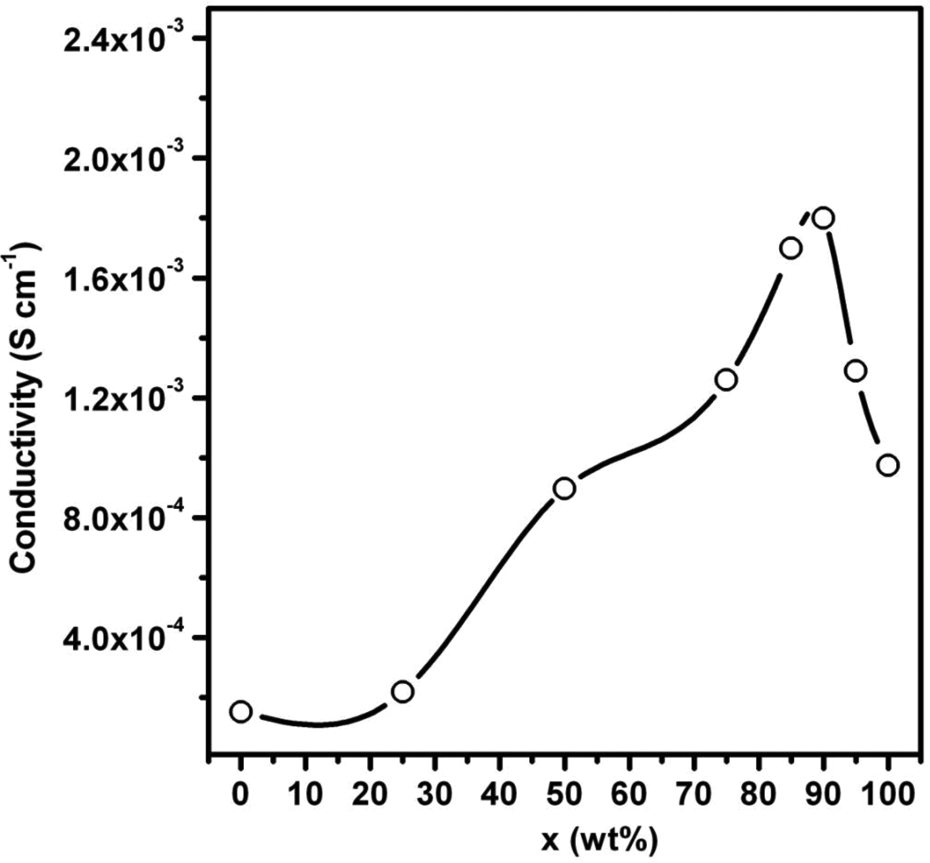
Composition dependence of conductivity of the GPE 35[(100 − x)PMMA + xPVdF-HFP] + 65[1 M NH4SCN in EC:PC] at room temperature. GPE: gel polymer electrolyte; PMMA: poly(methyl methacrylate); PVdF-HFP: poly(vinylidene fluoride hexafluoropropylene); NH4SCN: ammonium thiocyanate; EC: ethylene carbonate; PC: propylene carbonate.
Electrochemical stability window
The measurement of working voltage range was carried out using CV on the SS | blend GPE | SS cell for the highest conducting composition x = 90 wt%. The obtained voltammogram of the blend GPE is shown in Figure 2. As can be seen, the voltammogram does not show any reduction or oxidation peak in the potential range from −1.6 V to +1.6 V and beyond that the current starts increasing rapidly. This gives the electrochemical stability window for the blend GPE to be approximately 3.2 V. This indicates a wider potential range of a nonaqueous proton-conducting GPE.

Cyclic voltammogram of the GPE 35[10PMMA + 90PVdF-HFP] + 65[1 M NH4SCN in EC:PC]. GPE: gel polymer electrolyte; PMMA: poly(methyl methacrylate); PVdF-HFP: poly(vinylidene fluoride hexafluoropropylene); NH4SCN: ammonium thiocyanate; EC: ethylene carbonate; PC: propylene carbonate.
Battery characteristics
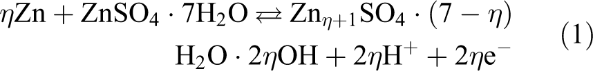
The best conducting composition (x = 90 wt%) of the GPE has been used to fabricate the proton battery with the configuration of Zn:ZnSO4·7H2O (anode) | 35[(10 PMMA + 90 PVdF-HFP] + 65LE] | PbO2:V2O5 + C + electrolyte (cathode). The Zn metal of the mixture (Zn + ZnSO4·7H2O) used as anode gives electrons to the external circuit through the oxidation of Zn to Zn2+, while hydrated ZnSO4·7H2O provides protons (H+ ions) to the electrolyte for transport through the proton-conducting GPE membrane. The anodic reaction, as suggested by Guitton et al.,
1
at the negative electrode is given as
On the cathode side, mixture of PbO2 and V2O5 serves as a well-known intercalating material with good electronic conductivity and reduction potential. This mixture has been used as the cathode material in many previously reported proton batteries.
2,3,9
–11
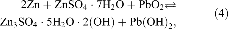
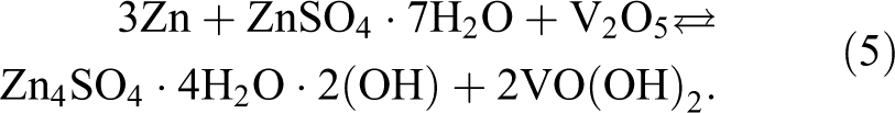
At the positive electrode, the reduction reactions of PbO2 and V2O5 may be given using the following equations
12
:


With the help of the above half cell reactions, the following complete cell reaction may be written as:
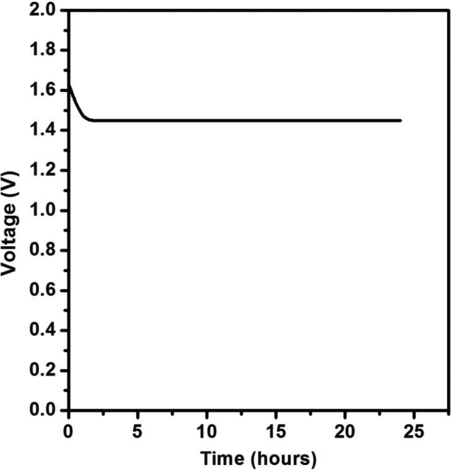
Immediately after fabrication of the cell, the OCV measurement was performed. Figure 3 shows voltage response of the cell as a function of time in the open circuit condition. The plot shows that the cell is reasonably stable in the open circuit condition. The OCV of the cell has been found to be 1.45 V. The value of OCV of the cell is expected to be approximately 1.7188 V taking into account the standard oxidation potential of Zn (−0.7618 V) and reduction potential of V2O5 (0.957 V). It may be noted that the reduction potential of V2O5 has been taken as standard over the reduction potential of PbO2 (1.455 V). This difference between the expected and the experimental OCV may be due to the possible reduction of ZnSO4·7H2O at the anode.
5
Figure 4 shows discharge characteristics of the battery at the resistive loads of 1 MΩ, 150 kΩ, and 15 kΩ. The initial voltage drop before discharge plateau in each cell is attributed to the activation polarization.
3,10,11
The internal resistance of the battery has been evaluated using the following relation: Discharge characteristics of the fabricated cell at different loads. Variation of OCV with time. OCV: open circuit voltage.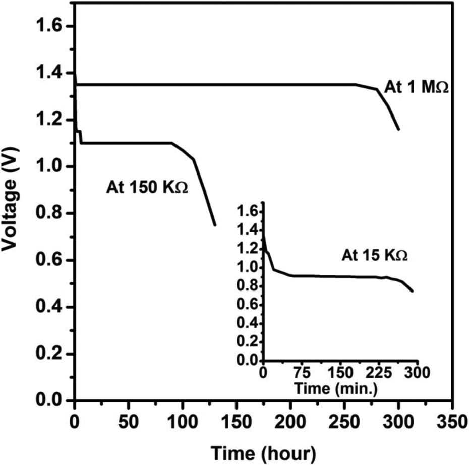
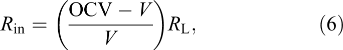
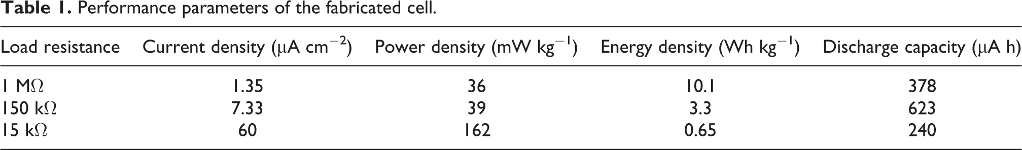
where V is the instantaneous voltage and R L is the load resistance. The average value of the internal resistance of the battery has been found to be approximately 59 kΩ. Different performance parameters of the battery as evaluated from the discharge pattern are listed in Table 1. It is observed that at high load resistance of 1 MΩ, the cell remains stable at 1.35 V for approximately 275 h and provides maximum energy density of 10.1 Wh kg−1. The energy density decreases continuously on decreasing load resistance (or at higher current drain) and the minimum energy density is obtained as approximately 0.65 Wh kg−1 at 15 kΩ load. The above observations show that performance of the battery is comparatively good at low current drain. It is also observed that the discharge capacity cell is the maximum at intermediate load of 150 kΩ compared with its discharge capacity at 1 MΩ and 15 kΩ.
Performance parameters of the fabricated cell.
The rechargeability of the cell was monitored in the potential range 1.0–1.4 V (Figure 5) through a current of 10 µA for 10 cycles. Quick charge/discharge has been observed after first three cycles. The discharge capacity plot corresponding to the cycle number is shown in the inset of Figure 5. It may be observed that after three discharge cycles, discharge capacity of the cell fades away significantly. This may be due to the poor intercalation and de-intercalation of H+ ions at the cathode. Structural changes in the cathode materials and the poor interfacial stability of the electrodes may be the possible reasons behind the capacity loss, which need further investigations for improving the cell performance.
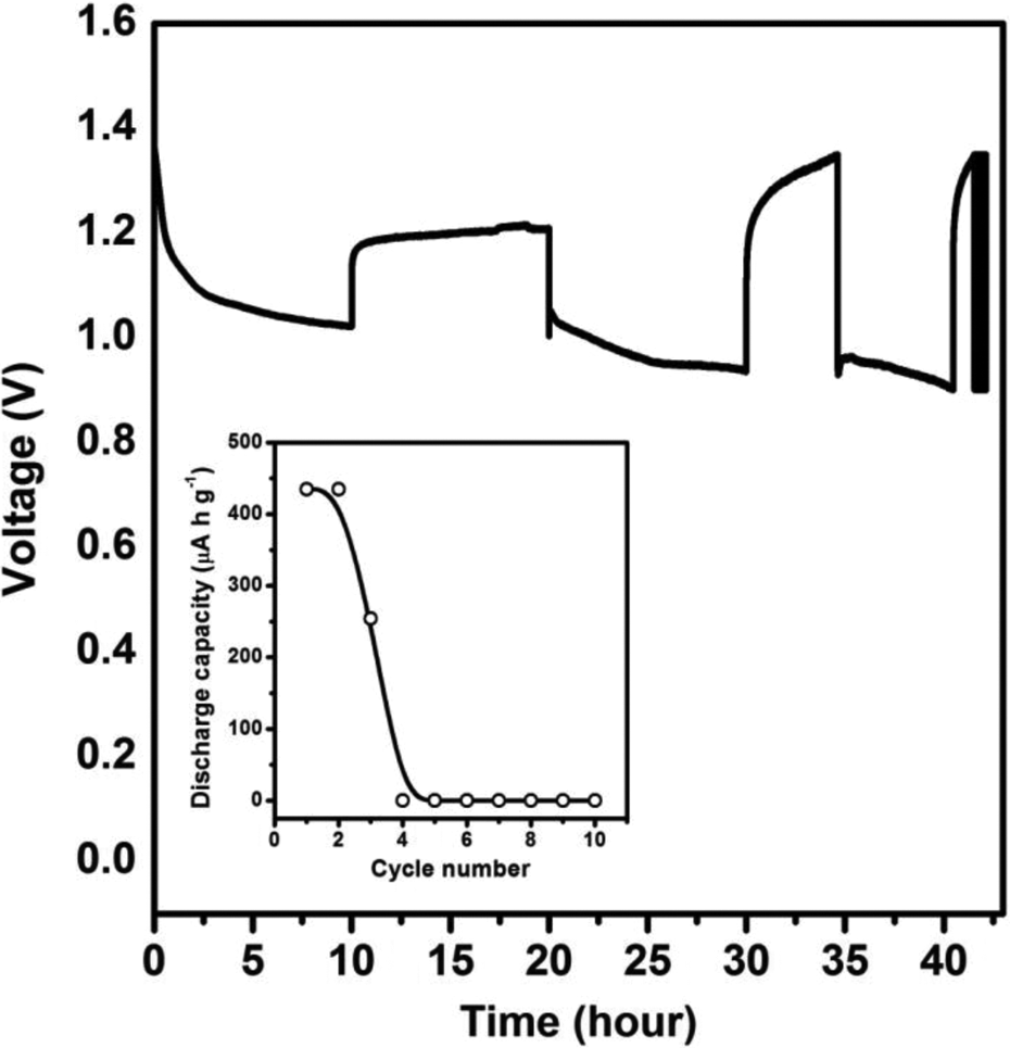
Charge–discharge curve of the fabricated cell. The inset shows the discharge capacity.
Conclusions
A proton-conducting GPE system based on PMMA/PVdF-HFP blend and LE solution of NH4SCN in EC:PC has been prepared in the form of freestanding and transparent membranes. The highest ionic conductivity obtained from the system is 1.9 × 10⁻³ S cm−1 for the composition with 10 wt% PMMA/90 wt% PVdF-HFP, which is higher than the GPE membranes of constituent polymers. The proton battery, fabricated using the optimized GPE composition, has been found to be stable in open circuit conditions with an OCV of 1.45 V. The battery performance parameters indicate that the battery is worthy for low current density applications.
Footnotes
Funding
This research received no specific grant from any funding agency in the public, commercial, or not-for-profit sectors.