






Abstract
Short carbon fiber–reinforced epoxy composites (SCFRPs) are attracting increasing attention because of their excellent mechanical properties and simple molding process. However, their mechanical, magnetic, and electrical performances have been the main concern, while their flame retardant performance has not been comprehensively studied. In this article, short carbon fiber–reinforced epoxy resin composites were prepared via the method of solution blending. The effects of carbon fiber on the flame retardancy and thermal stability of epoxy resin composites were studied by a UL-94 horizontal combustion test, a cone calorimetry test, and thermogravimetry analysis. The results showed that when the short carbon fiber was 0.7 wt%, the combustion level of the material increased from FH-1 to FH-2; the peak values of the heat release rate and total heat release were reduced by 31.6% and 11.36%, respectively. Thermogravimetry analysis showed that the temperature at the maximum decomposition rate was improved by 9°C, and the decomposition rate was decreased simultaneously. The mechanical properties of the composites were improved as well.
Introduction
There are many excellent properties of epoxy resin, such as high tensile strength, high modulus, excellent dimensional stability, and electrical insulation, and it is widely used in the aviation and electronics industries, among others. 1,2 Carbon fibers are among the main reinforcing fibers of advanced composites because of their excellent properties, such as high strength, small specific gravity, small thermal expansion coefficient, high thermal conductivity, and high design freedom. 3 Carbon fiber–reinforced epoxy resin composites (CFRPs) are the world’s most advanced composites and have many excellent performance characteristics, such as high strength, structural stability, and high temperature and chemical stability; they can be used as a structural material load, as well as a functional material in a role that is widely used in high-tech fields, automotive, construction, and other civilian areas. 4,5
At present, the properties of force, heat, electricity, and magnetism for short carbon fiber–reinforced epoxy resin have been extensively studied. The related studies show that the addition of an appropriate amount of short carbon fiber (SCF) has a certain effect on these properties of epoxy resin composites. Zhang et al. made a preparation of a low-viscosity liquid epoxy resin-modified hyperbranched short carbon fiber–reinforced composite (SCFRC) and found that the mechanical and thermal properties of SCFRC increased first and then decreased with the increase in Hyper E102 content. 6 Srivastava et al. characterized SCF/carbon nanotube (CNT)-reinforced epoxy composites via mechanical experiments and conductivity tests, and it was shown that the mechanical and electrical properties of the material depend on the type of SCF and the presence of multi-walled carbon nanotube (MWCNT). 7 Unterweger et al. studied the mechanical and thermal properties of fiber-reinforced composites using different sizes and types of fiber, and studies showed that fiber/matrix interactions have an important effect on the properties of composites. 8 De Rosa et al. mixed carbon black, carbon fiber, and MWCNTs into epoxy resins at various ratios, and the numerical simulations demonstrated the feasibility of designing new electromagnetic micro/nanostructure shields and radar absorber laminates; the total thickness of the screen was reduced to less than 2 mm using a lossy sheet made of a three-phase composite material. 9 Graphene foam (GF), carbon fiber (SCF), and GF/SCF-reinforced epoxy resin composites were prepared by Huang et al. It was found that GF/SCF-reinforced epoxy resin showed higher thermal conductivity than that of single GF- or SCF-reinforced epoxy resin. 10
In this article, the effect of SCF on the flame retardancy of epoxy resin composites was studied. The effect of SCFs on the mechanical properties of the composites was studied simultaneously. First, the carbon fiber was modified by liquid-phase oxidation and a silane coupling agent, and then the modified CFRPs with different contents were prepared by solution blending. The effects of carbon fiber on the flame retardancy and thermal stability of epoxy resin composites were studied by the UL-94 horizontal combustion test, cone calorimetry, and thermogravimetry analysis. The effects of carbon fiber on the mechanical properties of epoxy resin composites were studied by tensile and flexural tests, and the surface morphology and microstructure of the composites were characterized by scanning electron microscopy.
Experiments
Materials
AralditeLY1564SP epoxy resin and PAN-based carbon fiber (T300) with a diameter of 6.91 μm and a length of 1–3 mm are the main materials. The requirements for analytical analysis include sodium dodecylbenzenesulfonate, concentrated nitric acid (65%), silane coupling agent (KH-550), ethyl acetate, and absolute ethanol.
Surface modification of carbon fibers
The original carbon fiber has many impurities on its surface, including some gum, 11 which should be cleaned. First, the SCF was put into a certain proportion of absolute ethanol, and then the mixture was sonicated for 2 h and washed with deionized water repeatedly until the solvent was removed; finally, it was placed in a vacuum oven and dried at 120°C for 1–2 h.
The surface of the original carbon fiber is relatively smooth, the surface area is small, the number of active carbon atoms on the edge is less, the surface energy is low, the contact angle is large, and its surface is liquid repellent such that it has poor adhesion with the resin matrix. 12 It is subjected to liquid-phase oxidation treatment on its surface to introduce functional groups such as –OH to increase the surface polar groups thereof, thereby improving the liquid repellency of SCF and enhancing the interfacial adhesion with the resin. The method comprises putting the cleaned carbon fiber into concentrated nitric acid and treating it with a water bath at a constant temperature (80°C) for 4–6 h. It was then rinsed with distilled water until the pH became neutral, at which point it was placed in a vacuum oven and then dried and cooled after bagging.
Preparation of the SCF/EP composites
A certain amount of oxidized carbon fiber, silane coupling agent (KH-550), dispersant (sodium dodecylbenzenesulfonate), and ethyl acetate were weighed. They were then poured into a beaker and ultrasonically dispersed for 30 min. A quantity of epoxy resin, which was added to the mixture, was stirred uniformly and then dispersed ultrasonically for 30 min. The mixed solution was placed in a hot water bath at 90° and boiled until the ethyl acetate was completely removed. It was then checked whether the mixture has a lot of bubbles. If there are air bubbles, defoaming is performed. The curing agent was weighed based on whether the mass ratio of the epoxy resin to the curing agent was 100:34 and slowly stirred evenly. Finally, the mixture was poured into a mold (a good stripping wax that was preheated), placed in a blast oven at 80°, and dried for 5 h. The investigated mass fractions of carbon fiber were 0, 0.5%, 0.7%, 1.0%, and 1.5%.
Characterization of the SCF/EP composites
The UL-94 horizontal combustion test is used to test the flame retardancy of the sample. The sample size is 125 × 13 × 3 mm. Three samples are required for each group, and the average is taken as the final result. A cone calorimetric test is used to test the combustion characteristics of the sample, the required sample size is 100 × 100 mm, and the thickness is 3–5 mm. Three samples are required for each group, and the average is taken as the result. The size of the sample required for the tensile test is shown in Figure 1. Five valid samples are required for each group, and the average is taken as the result. The size of the sample required for the flexural test is 80 × 15 × 4 mm. Five valid samples are required for each group, and the average is taken as the result. Scanning electron microscopy is used to analyze the microstructure.
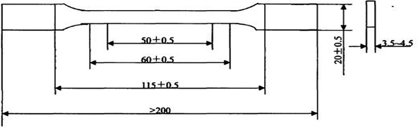
Dimensional drawing of the tensile test specimens.
Results and discussion
UL-94 horizontal combustion test
The UL-94 horizontal combustion test is used to measure the burning performance of the material by measuring the linear burning rate or the burning length, and the material is placed in the laboratory with a small flame that is ignited horizontally. 13 The burning level in descending order is FH-1, FH-2, FH-3, and FH-4. It can be seen from Table 1 that the combustion level of the epoxy resin composites with carbon fiber is higher than that of the resin matrix, which indicates that the carbon fiber suppresses the diffusion rate of the material to a certain extent, thus enhancing the flame retardancy of the epoxy resin composites. When the carbon fiber is 0.5 wt%, the material burning level is the same as that of the resin matrix, but its burning rate is significantly smaller than the resin matrix and accompanied by melt drops. With the increase in the content, the combustion level of SCF/EP composites was increased to FH-2, and the droplet was dripped. When the carbon fiber is 1.0 wt%, the burning length is the smallest, which indicates that the carbon fiber has the best effect on the flame retardant enhancement of the material. When the carbon fiber is 1.5 wt%, the combustion level of the material is lowered, which may be because there are too many carbon fibers to be dispersed evenly in the resin matrix, resulting in some defects, specifically showing the formation of many pores in the matrix.
UL-94 test results for different samples.a
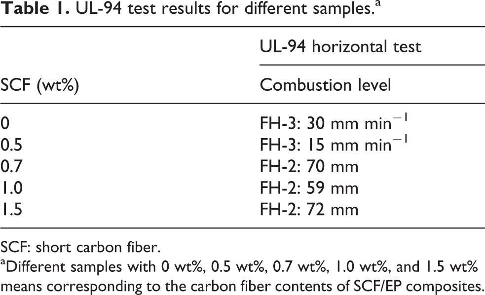
SCF: short carbon fiber.
aDifferent samples with 0 wt%, 0.5 wt%, 0.7 wt%, 1.0 wt%, and 1.5 wt% means corresponding to the carbon fiber contents of SCF/EP composites.
Cone calorimetric analysis
The combustion characteristics of different samples were tested by a radiation intensity of 35 kW m−2. The flame retardancy of different samples was analyzed by the heat release rate (HRR), total heat release (THR) and mass loss rate (MLR). The flue gas and toxicity were analyzed by the total smoke production (TSP), specific extinction area (SEA), carbon monoxide generation rate, and so on.
The HRR curves are shown in Figure 2(a). The peak HRR is the most important parameter characterizing the flame retardancy of the material. 14 It can be seen from Table 2 that the HRR of the epoxy resin matrix is rapidly increasing after ignition; the ignition time of the epoxy resin matrix is 52 s; the peak HRR is 971.7 kW m−2. The ignition time of the epoxy resin composites with carbon fiber was significantly delayed, and the peak heat release rate was significantly decreased. When the SCF was 0.7 wt%, the peak value of the HRR of the composites decreased significantly, and the ignition time was delayed by 28 s. When the SCF is 1.5 wt%, the ignition time of the material is prominently prolonged. This is mainly because the SCF inhibits the thermal decomposition of the epoxy resin, thus inhibiting the release of combustible gases.
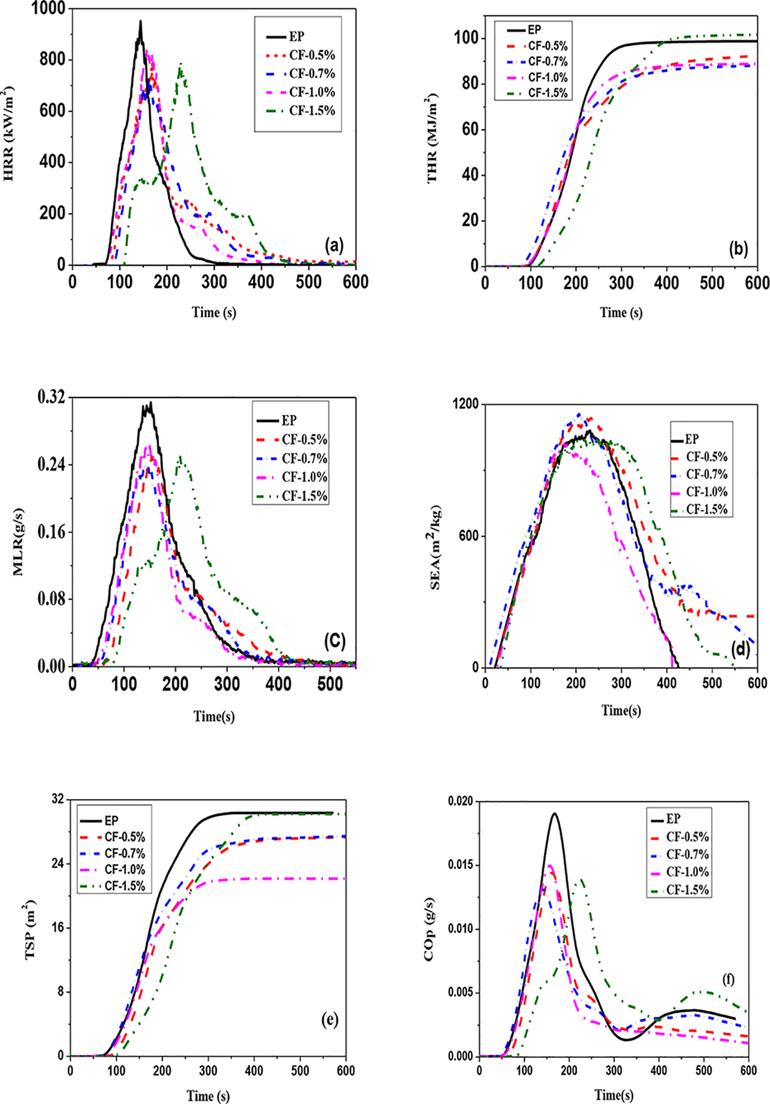
The characteristic curves of different samples. (a) Heat release rate of samples, (b) total heat release of samples, (c) mass loss rate of samples, (d) specific extinction area of samples, (e) total smoke product, and (f) product of the CO of samples.
Related data of different samples from cone calorimetry.
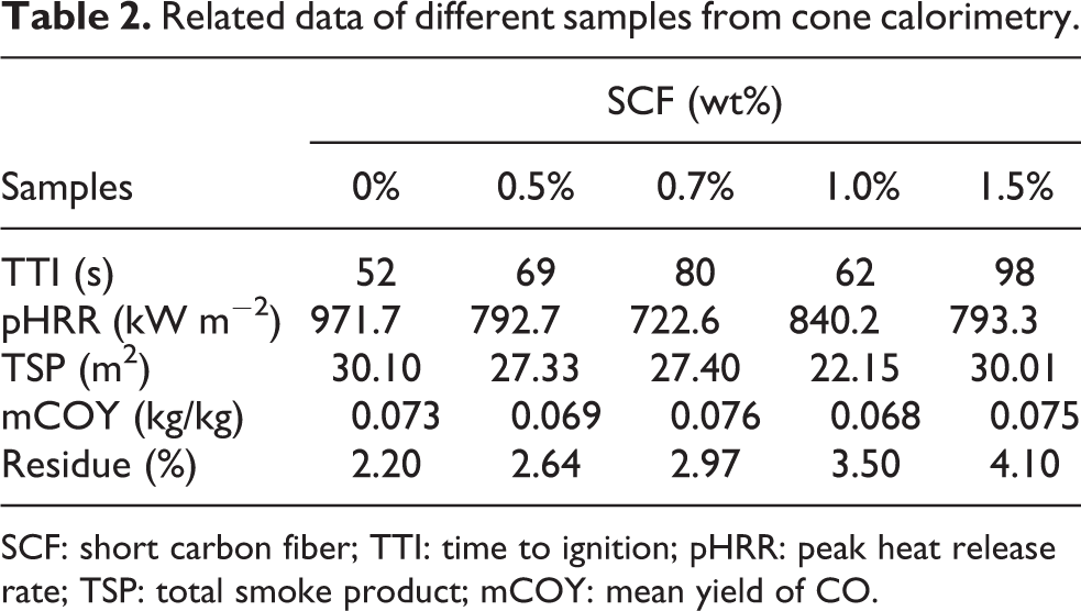
SCF: short carbon fiber; TTI: time to ignition; pHRR: peak heat release rate; TSP: total smoke product; mCOY: mean yield of CO.
The THR profiles for samples with different SCF contents are shown in Figure 2(b). In contrast, the total thermal release (98 MJ m−2) of pure epoxy resins is much higher than that of SCF/EP composites. When the SCF is 0.7 wt%, the maximum heat release of the composites is decreased by 11.36%. In addition, the THR of pure epoxy resin increases rapidly at 80–200 s, which corresponds to the HRR curve during that time. When the SCF is less than 1.5 wt%, the THR of SCF/EP composites is almost the same, but the slope of the curve is obviously reduced, indicating that the addition of SCF can delay the flame spread.
The MLR curves are shown in Figure 2(c). The MLR reflects the ease of decomposition of the material. 15 Compared with the matrix, the initial time of the thermal decomposition of the composites with SCF addition was delayed, and the peak MLR was significantly reduced. This is mainly due to the excellent heat resistance of the SCF, capable of absorbing most of the heat, as well as some of the heat transfer to the epoxy matrix through the two-phase interface in the process of energy loss. When the SCF is 0.7 wt%, the peak MLR is the smallest, and when the SCF is 1.5 wt%, the time of initial decomposition is obviously lagging behind that of other samples. The curve is similar to that of the HRR curve, and it exhibits a lower peak at the beginning and then rapidly becomes larger; a second peak appears, which is due to the SCF content being dispersed unevenly in the matrix. It is shown that SCF is relatively less in the surface, but it is in good contact with the resin. However, due to the uneven dispersion of SCF inside the resin matrix, it forms a weak bond interface with the substrate, producing more pores and resulting in a rapid increase in the rate of mass loss.
The SEA curves are shown in Figure 2(d). The SEA is an important parameter that characterizes the strength of the smoke produced by the unit mass at the moment of combustion. 16 It can be seen from the figure that the material produces smoke later when the carbon fiber is 1.0 wt%. At approximately 150 s, it reaches the peak and then drops rapidly. At approximately 410 s, it is no longer smoking. While the other samples continue to increase at 150 s, the time to terminate the production of smoke is significantly later. This shows that a certain amount of carbon fiber can inhibit the pyrolysis of materials to a certain extent.
The total smoke generation and carbon monoxide production rate are the main parameters to characterize the toxicity. 17 It can be seen from Figure 2(e) that the total smoke consumption of the epoxy resin composite with carbon fiber is smaller than that of the resin matrix, and the time to start to smoke is delayed much more than the matrix. The slope of the curve also shows that it is relatively slower than the matrix resin in smoke releasing. It can be seen from Table 2 that, when the carbon fiber is 1.0 wt%, the TSP is the lowest, with a reduction of 26.41%. This is consistent with the SEA curve. At the same time, it can be seen from the production rate of carbon monoxide (COP) curve of Figure 2(f) that the COP of the epoxy resin composite with carbon fiber is smaller than that of the epoxy resin matrix in the first 300 s. As the material burned out early, the material under the action of thermal radiation showed insufficient combustion because of the protection of the carbon layer, resulting in the COP being on the rise from 300 s to 600 s. At approximately 550 s, the COP begins to decline, mainly because the flame has been extinguished at this time. As the material forms residual carbon, the pyrolysis of the residue becomes weak. As seen from Table 2, when the carbon fiber was 1.0 wt%, the average yield of carbon monoxide was the lowest, with a reduction of 6.85%. In summary, a certain amount of carbon fiber can inhibit the smoke of epoxy resin to a certain extent.
Morphology and microstructure of the products of combustion analysis
In contrast to Figure 3(a) and (b), the epoxy matrix burns out and has only a small amount of ashes at the edge, away from radiant heat, while the SCF/EP combustion productions are intact and clearly visible in the carbon fibers dispersed therein. It is laminated with epoxy resin residual carbon to form a tight network structure. As seen from Figure 3(c), the epoxy resin is involved in the carbon formation process, which is mainly due to the higher carbon–oxygen ratio in the epoxy resin molecular chain. The carbon layer formed by the epoxy resin is a honeycomb structure that is capable of isolating the generation and escape of the combustible gas and suppressing the intervention of the oxygen, 16 thereby reducing the heat release amount of the pyrolysis reaction and the thermal conductivity of the combustion material. It can be seen from Figure 3(d) that the residual carbon of the epoxy resin is coated on the surface of SCF and is relatively complete. It can be seen from Table 2 that the residual carbon formed by the SCF/EP composite material is more than that by the resin matrix. In addition, it increases with the increase in content, which shows that SCF can promote the carbon formation of the epoxy resin composite. Thus, on the one hand, the carbon layer formed by the epoxy resin is capable of isolating the gas and reducing the heat exchange. 18 On the other hand, carbon fiber can promote the carbon formation of epoxy resin but also play its high heat resistance, which synergistically decomposes heat. Thus, the heat required for pyrolysis materials becomes larger, thereby enhancing its flame retardant properties.
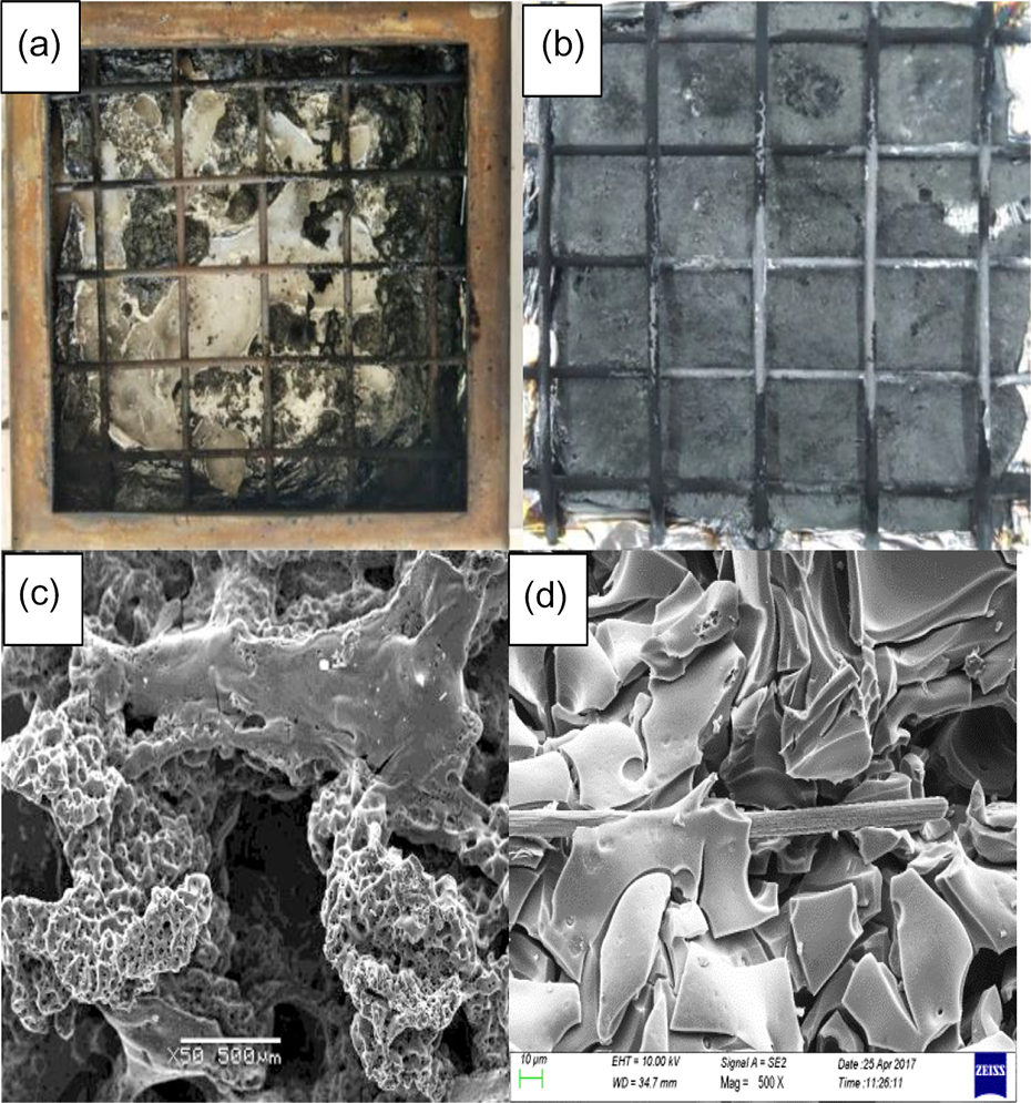
SEM of the combustion products. (a) Morphology of combustion products of EP and (b) SCF/EP composites. (c) Microstructure of residual carbon of EP and (d) SCF/EP composites. SEM: scanning electron microscopy; SCF: short carbon fiber.
Thermogravimetry analysis
To study the thermal stability of the material, it was raised from 20°C to 800°C in an air atmosphere at a rate of 10°C min−1. The curves of thermogravimetry (TG) and differential thermogravimetry (DTG) for different composites are, respectively, shown in Figure 4. The decomposition temperatures for each stage of different composites are shown in Table 3. T5% represents the temperature when the weight loss was 5%, which represented the onset decomposition temperature. Tmax represents the temperature at the maximum decomposition rate, subtracted from DTG curves. T95% represents the temperature when the weight loss was 95%, which represents the terminal decomposition temperature.
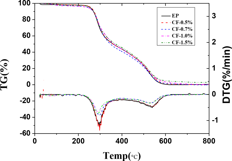
The curves of TG and DTG for different composites.
The decomposition temperatures for each stage of different composites.
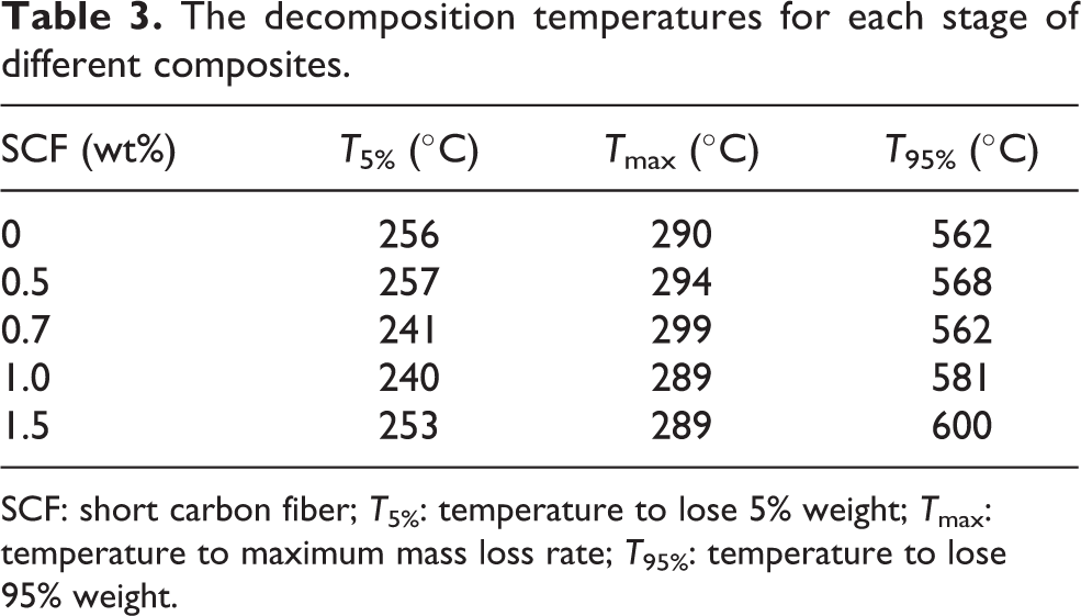
SCF: short carbon fiber; T5%: temperature to lose 5% weight; Tmax: temperature to maximum mass loss rate; T95%: temperature to lose 95% weight.
It can be seen from Figure 4 that the mass residual curve during the thermal decomposition of the material decreases stepwise with increasing temperature. In the first 200°C, compared with SCF/EP and EP composites, the onset decomposition temperature is almost the same, indicating that the addition of carbon fiber did not improve its initial decomposition temperature. Between 200°C and 400°C, the mass residue of the material decreases rapidly, and the corresponding peak of the DTG curve appears. In this temperature range, the maximum MLR was observed for all samples. The peak area represents the size of the mass loss. The peak indicates that the epoxy resin has undergone intense decomposition at this time. It can be seen from Table 3 that the first peak of the epoxy matrix appears at 290°C, while the first peak of the composites appears at 299°C when the SCF is 0.7 wt%, which is an improvement of 9°C. The peak area of SCF/EP composites is smaller, indicating less loss of mass. Simultaneously, it indicates that the carbon fiber inhibited the pyrolysis of epoxy resin composites to a certain extent. Between 400°C and 600°C, the mass of the material decreases for the second time, and the corresponding peak of DTG appears. The area of the peak is small, and the material residue is basically residual carbon. The appearance of the peak is mainly due to the occurrence of oxidative decomposition of residual carbon when exposed to the air in the atmosphere at a certain temperature. The quality of the corresponding material appears second to a greater reduction. From the microscopic analysis, the mass reduction of the composites is mainly due to the pyrolysis of the resin matrix. The pyrolysis of the resin matrix is mainly because some molecular chains have lower dissociation energies, and their weakly bonded ends appear randomly at the beginning of the lower temperature. As the temperature increases, other chemical bonds with higher dissociation energies are also decomposed into low molecular weight products.
Mechanical properties analysis
Analysis of tensile and bending test results
According to the performance test method of GBT2567-2008, the tensile test and the three-point bending test were carried out. The influence of SCF on the mechanical properties was studied by the test results. As shown in Figure 5, when SCF is 0.5 wt%, its strength is smaller than that of the epoxy resin matrix itself. This may be because the addition of carbon fiber destroys the resin matrix structure, and a certain defect might be formed in its internals. Due to the reduced content, they are less able to withstand stress. 19 When SCF is 0.7 wt%, the flexural strength reaches 89.69 MPa, which is an improvement of 30%. When SCF is 1.0 wt%, the tensile strength reaches 55.61 MPa, which is an improvement of 5.2%. At the same time, the flexural performance of SCF-reinforced epoxy composites is better than that of tensile properties, which may be because of the SCF in the epoxy resin mixed with a certain orientation. 20 Additionally, the orientation effect may be more conducive to the flexural test stress dispersion, as this orientation is often the direction of the SCF dispersion stress. When SCF is 1.5 wt%, the strength is smaller than that of the matrix, which may be because there is so much carbon fiber in the resin matrix that the carbon fiber cannot be fully impregnated with the resin, and thus many weak bond interfaces are formed. When the material is stressed, the carbon fiber is desorbed from the weak interface, causing the stress transfer to lose its effect.
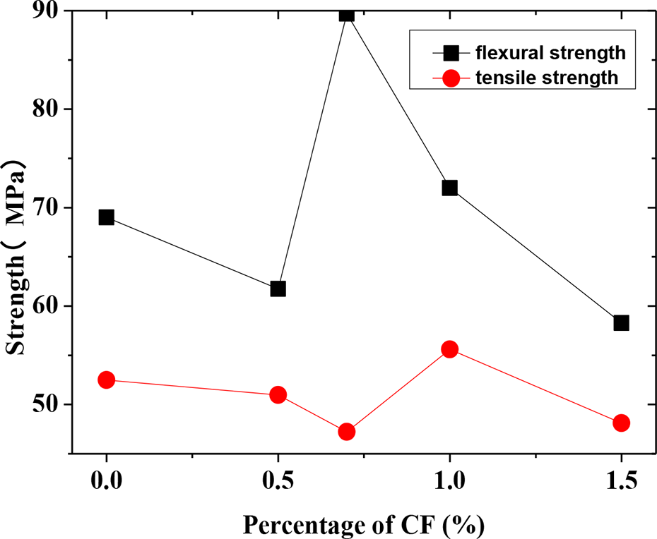
Tensile and flexural strength of different samples.
Analysis of the microstructure of the mechanical section
The scanning electron microscopy view of the tensile test section of different samples is shown in Figure 6. Epoxy resin is shown in Figure 6(a), and epoxy composites with SCF of 0.5 wt%, 1.0 wt%, and 1.5 wt% are shown in Figure 6(b), (c) and (d), respectively. It can be seen from Figure 6(a) that, when the carbon fiber is not added, the cross section is relatively smooth, and the crack is less and extends in the same direction as the brittle fracture. It can be seen from Figure 6(b) that, when SCF is 0.5 wt%, a hole appears on the fracture surface, which is obviously caused by the desorption of the fiber. This shows that the carbon fiber under the content breaks the epoxy resin structure such that it produces a certain flaw, which confirms the results of the macro experiments. It can be seen from Figure 6(c) that, when SCF is 1.0 wt%, it is found that the carbon fibers dispersed in the resin are less, but it can be seen from Figure 6(e) that the adhesion between the carbon fibers and the resin is relatively close. This indicates that the interfacial bonding is strong. After the material is stressed, the resin can transfer the stress to the carbon fiber, and the direction of the force will also be transmitted along the orientation of the carbon fiber 21 such that the carbon fiber can be uniformly applied, and the high strength characteristics of the carbon fiber can be effectively exerted. Transmitting this force also functions as an energy dispersion effect to a certain extent, thus improving the mechanical properties of the epoxy resin composites. As shown in Figure 6(d), when carbon fiber is 1.5 wt%, the carbon fiber dispersed in the epoxy resin is greater but relatively concentrated, and it can be seen from Figure 6(f) that there is a significant difference between the carbon fibers and the resin. The results show that the compatibility of the two phases is poor, and the damage of the composites occurs mainly at the interface between the fiber and the resin, which leads to fiber debonding and cannot enhance the mechanical properties of the epoxy composite. Considering the macroscopic and microscopic experiments, the carbon fiber content and the bonding strength of the interface are two key factors affecting the mechanical properties of carbon fiber–reinforced epoxy composites.
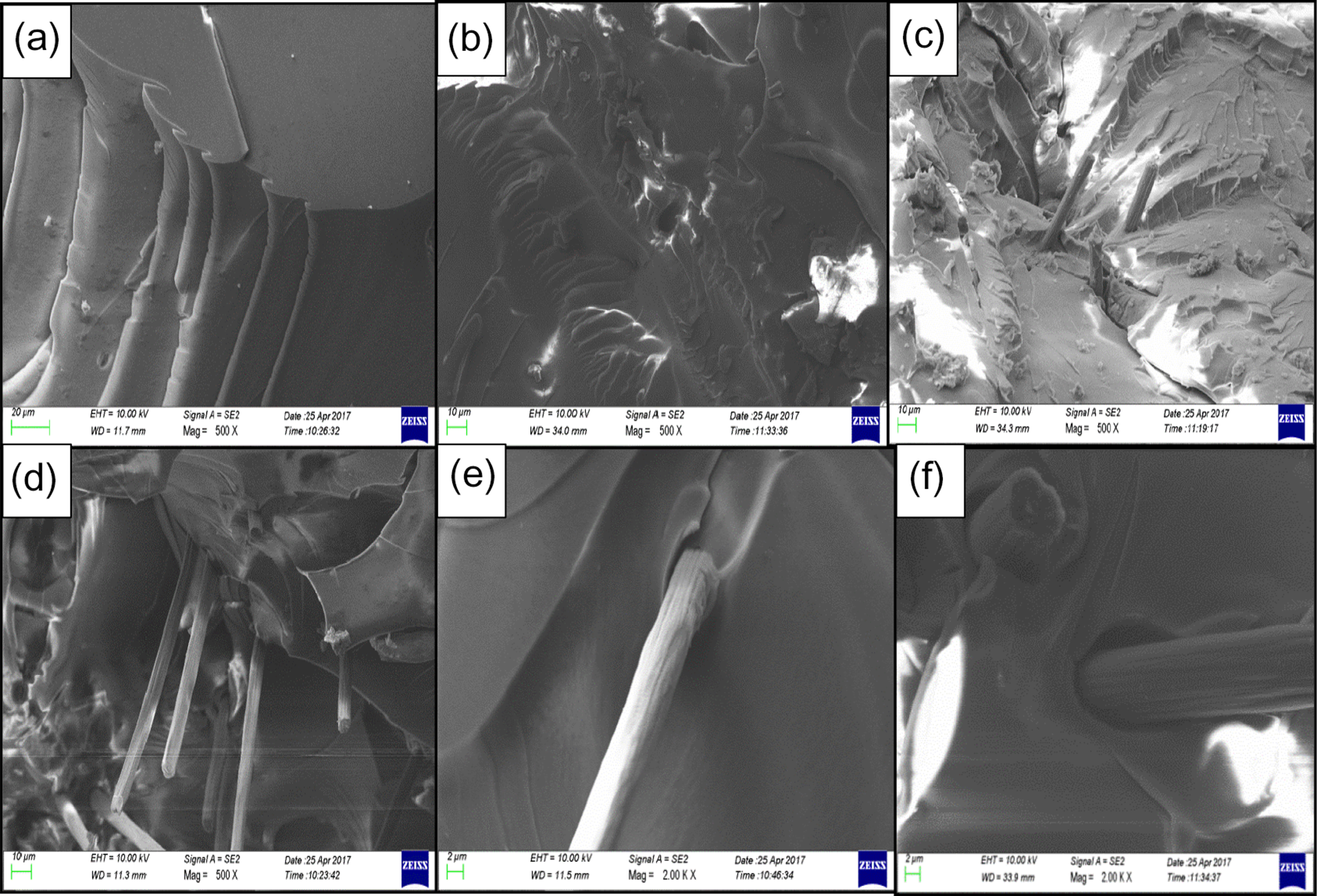
Histogram of the tensile test section of different samples. (a) Epoxy resin, (b) 0.5 wt% SCF/EP, (c) 1.0 wt% SCF/EP, (d) 1.5 wt% SCF/EP, (e) 0.7 wt% SCF/EP, and (f) 1.5 wt% SCF/EP. SCF: short carbon fiber.
In addition, it can be seen from Figure 6(e) and (f) that the surface etching of the carbon fiber has a lot of gully, which is relatively rough, which indicates that the modification treatment of the carbon fiber is effective. According to the theory of mechanical bonding and chemical bonding theory, 22 the modified carbon fiber and resin will produce a mechanical interlocking phenomenon, and the introduction of functional groups and resin matrix surface in the form of chemical bonds with each other has improved the bond strength. The enhancement of the mechanics also validates this point.
Conclusions
Based on the SCF/EP composites prepared by the method of solution blending, both the flame retardancy and thermal stability are improved (as shown by the UL-94 horizontal combustion test, cone calorimeter, and thermogravimetry analysis), and the mechanical properties are improved as well (as shown by mechanical tests). Some findings are as follows:
The UL-94 horizontal combustion test shows that the addition of SCF could inhibit the diffusion rate of epoxy resin composites and reduce the dripping. When SCF is 1.0 wt%, the combustion level is promoted from FH-1 to FH-2.
The cone calorimeter test shows that the flammability of the material deteriorates when SCF is 0.7 wt%, the ignition time is delayed for 28 s, and the initial temperature of the mass loss is improved. The HRR peak and THR are the lowest, with the decrease of 31.6% and 11.36%, respectively, compared with epoxy resin. When SCF is 1.0 wt%, the area of extinction is the smallest, and the total smoke and carbon monoxide production are reduced by 26.41% and 6.85%, respectively. Therefore, the addition of SCF can inhibit the smoke. The amount of carbon formed by the epoxy resin is increased due to the addition of carbon fibers.
Thermogravimetry analysis shows that the thermal stability of the epoxy resin composites is improved due to the addition of carbon fiber. Although the addition of carbon fiber did not improve its initial decomposition temperature, it improved the temperature at the maximum decomposition rate by 9°C, and the decomposition rate was decreased simultaneously.
The mechanical tests show that the flexural strength and tensile strength of the composites are enhanced because of the addition of carbon fiber, while the flame retardancy of the composites is improved. When carbon fiber is 0.7 wt%, the flexural strength is increased by 30%. When carbon fiber is 1.0 wt%, the tensile strength is increased by 5.2%.
Footnotes
Declaration of conflicting interests
The author(s) declared no potential conflicts of interest with respect to the research, authorship, and/or publication of this article.
Funding
The author(s) disclosed receipt of the following financial support for the research, authorship, and/or publication of this article: This work was supported by the Natural Science Foundation of Liaoning Province of China (grant no. 201602567).