






Abstract
Thermally conductive epoxy composites of 3-D boron nitride (BN) networks were synthesized via a facile template method, wherein an epoxy was infiltrated into the network. The 3-D BN network skeletons, which use polystyrene (PS) microspheres as a framework support, were prepared by hot compression and ablation techniques. Field emission scanning electron microscope indicated that the content of BN filler and its dispersion greatly influences the integrity and density of the resultant network. With a BN loading of 40 vol%, the composites showed a maximum thermal conductivity of 1.98 W mK−1, which is 1000% times higher than the pristine epoxy material. In addition, the thermal stabilities, mechanical properties, and dielectric properties of the fabricated BN/epoxy composites were also largely improved. This facile method is an effective approach to designing and fabricating composites with high thermal conductivities.
Introduction
The ongoing miniaturization of electronic devices and the rapid development of integrated microelectronics have stimulated the exploration of reliable, high-performance advanced packaging materials. 1 –4 In the microelectronics industry, epoxy resins are widely used for electronic packaging and electrical insulating due to their excellent thermal stabilities, mechanical properties, and low dielectric constants. However, the low thermal conductivity of these materials currently limits their application. 1,5,6 Therefore, many researchers have focused on the development of epoxy-based composite materials that have high thermal conductivities but are electrically insulating. 3,7
Melt and solution mixing are common methods for enhancing the thermal conductivity of a polymer and are used to introduce a large amount of thermally conductive fillers, such as graphite, 8 –10 carbon nanotubes, 11,12 metallic powders, 13 boron nitride (BN), 14,15 or aluminum nitride. 16 However, polymer-based thermally conductive composites prepared by these methods typically have a random distribution of filler particles. Therefore, a high content of filler is required to form a thermally conductive path, which inevitably leads to decreased mechanical properties and difficult processing. 7 Moreover, the enhanced thermal conductivity of filled polymer composites is usually limited by a high interfacial thermal resistance between the fillers and the polymer matrix. Therefore, the fillers are often surface-functionalized to minimize the interfacial thermal resistance between the fillers and the polymer, though this process is usually complex. 17 –20 All things considered, it is important to develop a novel and effective way to reduce the interfacial thermal resistance in these composites.
Recently, 3-D foam structures such as graphene have been highly studied because of their ideal network structures. 21,22 Unlike composites with randomly dispersed fillers, these 3-D foam structures could ensure the development of a thermally conductive path. However, techniques for constructing 3-D structures are usually complicated, especially if the filler is not a carbon-based material. 21 –23 For example, Conrado and Pavese 22 proposed a continuous 3-D graphene network; however, the composites prepared by this method had poor thermal conductivity, and this insulation problem is particularly important in electrical package applications. Xue et al. 24 demonstrated a template-free method for constructing foam-like BN porous materials with an ultrahigh specific surface area, but the homemade BN porous materials exhibited low crystallinity. Zeng et al. 23 reported an ice template method to construct 3-D BN networks in polymer composites, and their thermal conductivity reached 2.85 W mK−1, but the extremely complex procedure makes this technique unsuitable for industrialization. Thus, we propose a simple and efficient template method to construct 3-D BN networks.
In this work, an effective method was used to fabricate 3-D BN network skeletons using high temperature compression and ablation techniques. Subsequently, the 3-D BN skeleton was infiltrated with an epoxy resin to obtain hexagonal BN (h-BN)/epoxy composites. Using this technique, 3-D BN networks with different BN contents were successfully constructed in the epoxy composites, and the influence of h-BN on the thermal conductivity of the composites is discussed. The thermal stability, mechanical properties, and dielectric properties of fabricated BN/epoxy composites were also studied.
Experiment
Materials
The h-BN powder (approximately 13 μm, purity >99.5%) was provided by Dandong Rijin Science and Technology Co., Ltd, China. Polyvinyl alcohol (PVA; molecular weight [MW]: 1750 ± 50) was obtained from Sinopharm Chemical Reagent Co. Ltd (Shanghai, China). Deionized water was prepared in-house by a Thermo Scientific Easypure II system (Shanghai, China). PS with an average particle size of 50 μm was supplied by BaoLiMei Chemical Reagent Co. Ltd (Guangzhou, China). Epoxy JY257 was purchased from Changshu Jiafa Chemical Co., Ltd, China. All reagents were used as received.
Preparation of the h-BN 3-D porous skeleton
First, a given weight of the h-BN powder was dispersed in 20 ml of 3 wt% PVA solution using ultrasonication dispersion for 1 h to obtain a homogeneous dispersion. The PS microspheres were then added into the dispersion and stirred at a speed of 500 r min−1 at 90°C for 1 h. The resultant mixture was fully dried at 110°C overnight to remove any residual water. Finally, the mixture was compressed and maintained at a temperature of 120°C and under a pressure of 10 MPa for 20 min to obtain a slice with a thickness of 2 mm. The h-BN/PS microsphere composites with h-BN concentrations ranging from 20 vol% to 60 vol% were prepared. After the compression process, the slices of h-BN/PS composites were heated to 500°C for 1 h to ensure that the PS microspheres were completely burned out and the 3-D BN skeleton with porous structures was obtained.
Preparation of the h-BN/epoxy composites
To prepare the BN/epoxy composites, liquid epoxy resins were directly infused into the 3-D BN skeleton. The procedure was as follows: The epoxy resin and curing agent were uniformly mixed at 50°C using a magnetic stirring apparatus. The weight ratio of the epoxy resin versus the curing agent was 100:85. The 3-D BN skeleton was then completely immersed into the mixture solution for 1 h. Finally, the samples were cured at 90, 110, and 150°C for 2, 3, and 4 h, respectively. After infusing the epoxy resin, the composites maintained the same shape and size as the original slices, indicating that any possible deformations or shrinkages that may have occurred during the infiltration process were negligible. The preparation process is shown in Figure 1.
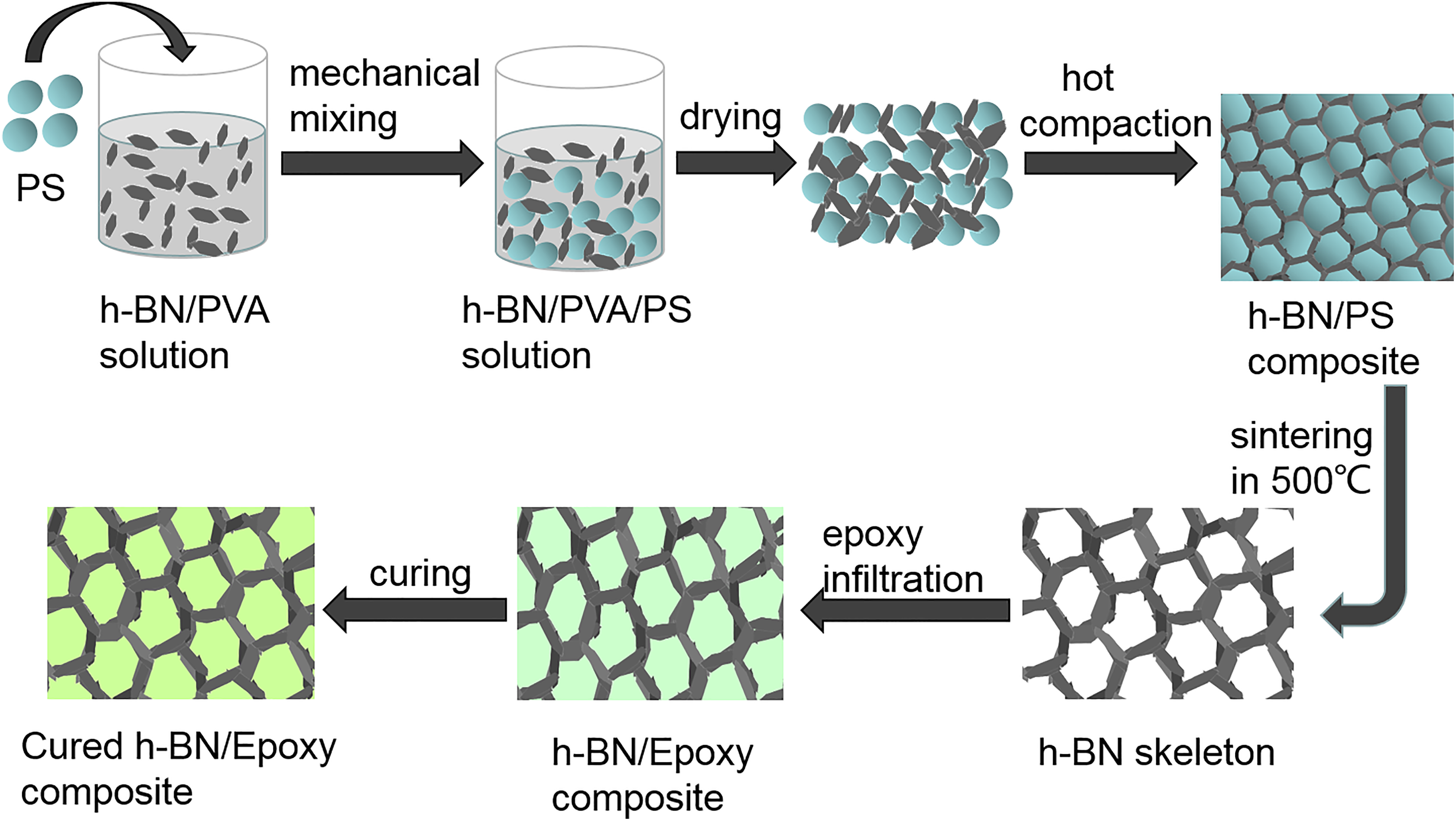
Schematic of the preparation process for the h-BN/epoxy composites. h-BN: hexagonal boron nitride; PVA: polyvinyl alcohol; PS: polystyrene.
Characterization
The framework was observed with a field emission scanning electron microscope (Sirion 200, FEI, Oregon State, Hillsboro, USA) operated at 10 kV. The fracture surface was sputtering with a layer of gold to avoid charge accumulation. The thermal conductivity of the composites was tested on a TCI thermal conductivity meter (C-Therm, Canada). Samples with a thickness of 2 mm were placed on the probe, and a drop of deionized water was dripped onto the probe to improve contact. The thermal properties were characterized by thermogravimetric analysis (TGA; Pyris 1, PerkinElmer, Waltham, Massachusetts, USA) under nitrogen atmosphere. The tests were run from 50°C to 700°C at a heating rate of 10°C min−1. A dynamic mechanical analyzer (DMA; Diamond, PerkinElmer, USA) was used to measure the mechanical properties of the samples as a function of temperature. The experiments were carried out in tension mode at the heating rate of 1 K min−1 under nitrogen atmosphere. The dielectric analyzer (HIOKI 3532-50, Japan) was used over the frequency range of 104−107 Hz. Circle-shaped samples with an area of 2.0 cm2 and thickness of 2.0 mm were coated with silver on both sides and used as electrodes.
Results and discussion
Structure of h-BN
The morphology of h-BN was examined via SEM (Figure 2(a)). It shows a flaky structure with average particle sizes of approximately 13 µm. Figure 3(a) shows the X-ray diffraction (XRD) pattern of h-BN. The peaks at 2θ = 27° were attributed to diffraction of the (002) planes of h-BN. Other peaks, which were observed at 2θ values of 41.5°, 43.8°, 50.1°, and 55.6°, were assigned to the (100), (101), (102), and (004) reflections, respectively, (JCPDS card no.34-042). 25

(a) Morphology of BN and (b) statistics of h-BN diameter distribution. BN: boron nitride; h-BN: hexagonal BN.
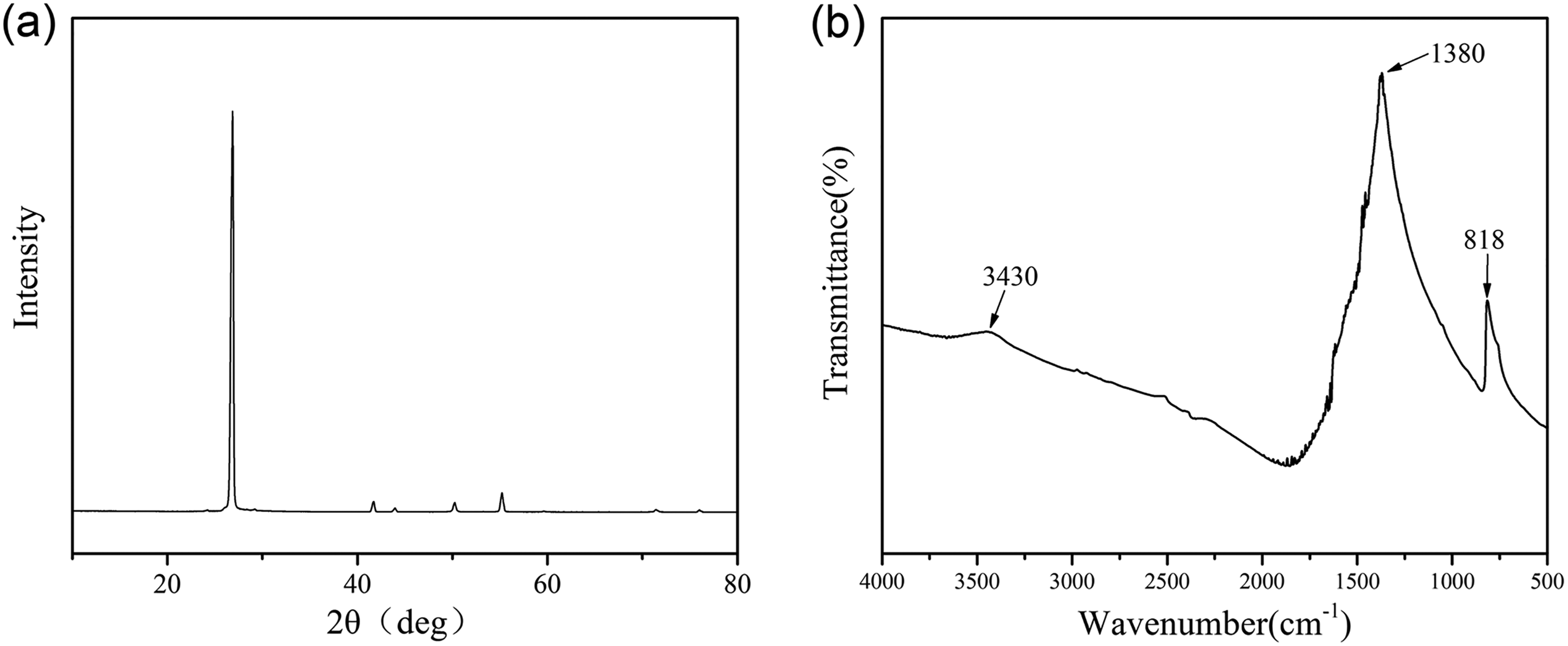
(a) X-ray diffraction (XRD) pattern of h-BN and (b) Fourier Transform infrared spectroscopy (FTIR) spectrum of h-BN. h-BN: hexagonal boron nitride.
Figure 3(b) shows the Fourier Transform infrared spectroscopy (FTIR) spectrum of h-BN. The strong absorption peak at approximately 1380 cm−1 was assigned to the in-plane stretching vibration of B–N, and the peak at 818 cm−1 was assigned to the out-of-plane bending absorption of B–N–B. The weak absorption band at 3420 cm−1 can be attributed to the stretching of hydroxyl groups at the edges of h-BN. 19
Morphology
Both the microstructure and dispersion of h-BN play an important role in synthesizing composites with effective thermal conductivities. Hence, the morphologies of the cross sections of the h-BN skeleton and h-BN/epoxy composites with various BN contents are observed by SEM, as shown in Figure 4(a) to (f). After the PS is removed at high temperature, a porous BN network structure (Figure 4(a)) is obtained. When the content of h-BN was lower than 40 vol% (Figure 4(b) and (c)), the h-BN plates could not connect with each other. Therefore, both the density and perfection of the formed network were relatively low. This dynamics is due to the PS microsphere agglomerating with each other during the preparation of the 3-D BN skeleton, which creates large areas for epoxy to infuse into. When the h-BN content reaches 40 vol% (Figure 4(d)), a more perfect 3-D BN network formed with a much improved density. Moreover, the stacking of BN sheets can greatly reduce the interfacial thermal resistance. Figure 4(e) and (f) shows that when the content of BN is higher than 40 vol%, a large number of h-BN particles stack together, forming many voids that lead to an incomplete infusion of epoxy and ultimately result in defects in the materials. Considering the discussion above, the most suitable h-BN content to achieve a network structure with continuous and robust fillers is approximately 40 vol%.
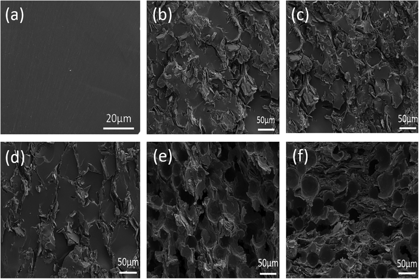
Cross-sectional SEM images of the h-BN/epoxy composite with various h-BN contents. (a) The h-BN skeleton before introducing the epoxy resin, (b) 20 vol% h-BN, (c) 30 vol% h-BN, (d) 40 vol% h-BN, (e) 50 vol% h-BN, and (f) 60 vol% h-BN. SEM: scanning electron microscope; h-BN: hexagonal boron nitride.
Thermal properties
As shown in the TGA curves (Figure 5), the main decomposition temperatures of the pure epoxy and h-BN/epoxy composites with different filler contents are similar at approximately 380°C. The decomposition temperature of the pure epoxy at 10% weight loss (T 10) was 300.4°C, while for the h-BN/epoxy composites, T 10 increases from 334.6°C to 365.7°C when the h-BN content increased from 20 vol% to 40 vol%. This slight shift of T 10 to a higher temperature indicates that the h-BN filler could improve the thermal stability of the epoxy matrix. This can be attributed to the ability of h-BN with high thermal conductivity to both disperse the heat during the combustion process as well as obstruct and isolate mass transport between the filler surface and polymer matrix. 26,27
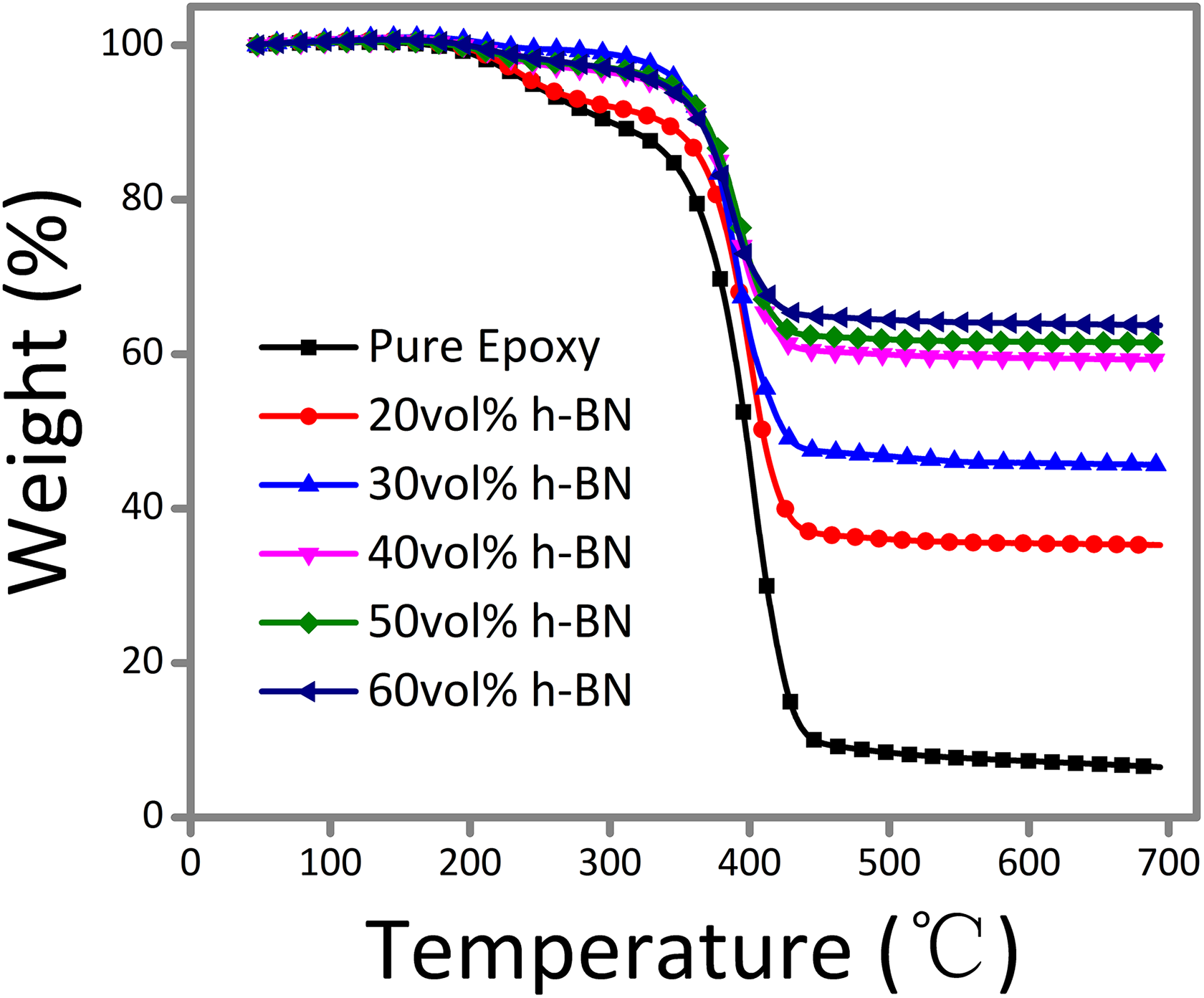
TGA curves of the epoxy resin and h-BN/epoxy composites. TGA: thermogravimetric analysis; h-BN: hexagonal boron nitride.
The thermal conductivities of the epoxy composites with different h-BN contents were measured and shown in Figure 6. It is believed that the morphology of the thermally conductive network will significantly impact the final thermal conductivity of the polymer composite. The pure epoxy has a low thermal conductivity of 0.18 W mK−1 at room temperature. When the h-BN content is 20 vol%, the thermal conductivity of the composites reached 0.99 W mK−1, as shown in Figure 6. Further increasing the amount of h-BN slightly enhanced the thermal conductivity. This dynamics may be due to h-BN plates being unable to form continuous thermally conductive paths at low volume fractions, as shown in Figure 7(a). Notably, with a filler loading of 40 vol%, the thermal conductivity of the composite reached the maximum value of 1.98 W mK−1. A possible explanation for this observation is that the 40 vol% loading provides enough h-BN to contact with each other and form net-like thermally conductive paths, similar to the complete model 3-D BN network shown in Figure 7(b). Interconnections with filler–filler overlap can largely reduce the contact thermal resistance of the material, 28 and the formation of dense, continuous, thermally conductive paths results in a large enhancement of the thermal conductivity to approximately 2 W mK−1.
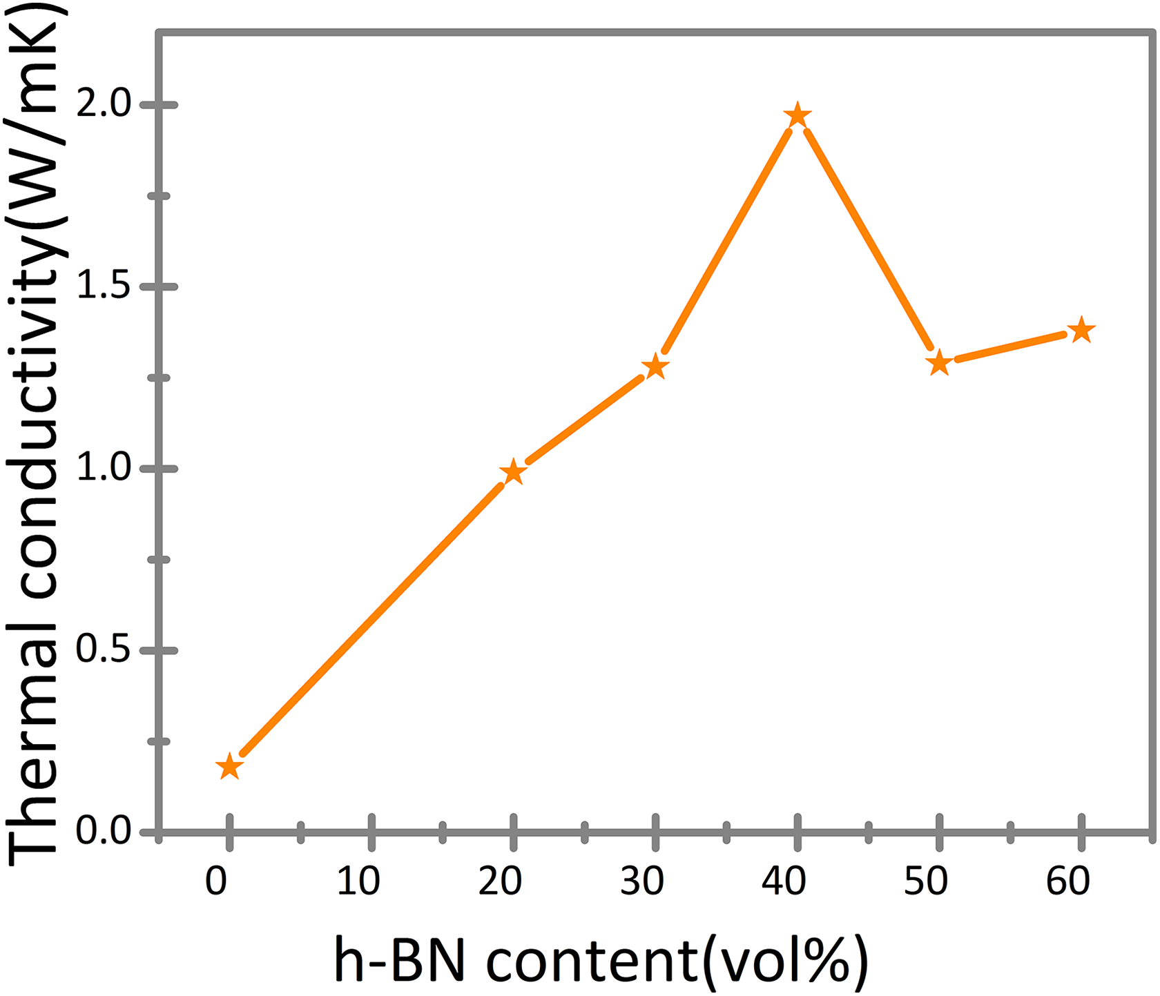
Thermal conductivity of the h-BN/epoxy composites as a function of h-BN contents. h-BN: hexagonal boron nitride.
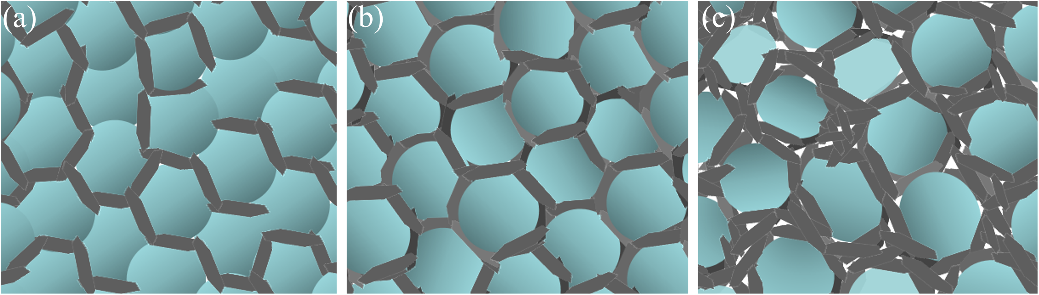
Models of the three types of network structures for h-BN/epoxy composites with various h-BN contents. h-BN: hexagonal boron nitride.
However, the thermal conductivity declines when the filler loading is higher than 40 vol%. This dynamics can be attributed to the defects in the network. Because there are too many rigid h-BN plates in disorganized stacks throughout the network, a number of voids appeared as shown in Figure 7(c). Moreover, when the h-BN content is increased to 60 vol%, the thermal conductivity slightly enhanced, which may be attributed to the broadened h-BN pathways that promoted the transfer of heat flux.
The above interpretation suggests that the most suitable h-BN content is 40 vol%, which gives the highest thermal conductivity coefficient in this work.
Dielectric properties
It is common knowledge that a low dielectric constant and low dielectric loss tangent are very important parameters for electronic packaging materials. A low dielectric constant is beneficial for reducing the signal propagation time in the electronic components and a low dielectric loss tangent can effectively decrease heat production in dielectric materials in an electric field. 4,5,29,30
The dielectric properties of the h-BN/epoxy composites as a function of filler content at different frequencies are plotted in Figure 8. As shown in Figure 8(a), the dielectric constants of the composites decrease with increasing h-BN content. The most plausible reason for this phenomenon is the restriction of bulk polarization in the epoxy resin, because h-BN causes immobility of the polymer chains, which ultimately decreases the dielectric constant of the composites. 31 However, as shown in Figure 9(a), there is a sharp decrease in the dielectric constant when the content of h-BN is above 40 vol%. This decrease may be caused by the formation of defects in the composites, which results in air-filled voids (air has a low dielectric constant of approximately 1). This explanation is consistent with the thermal conductivity results that were discussed above.
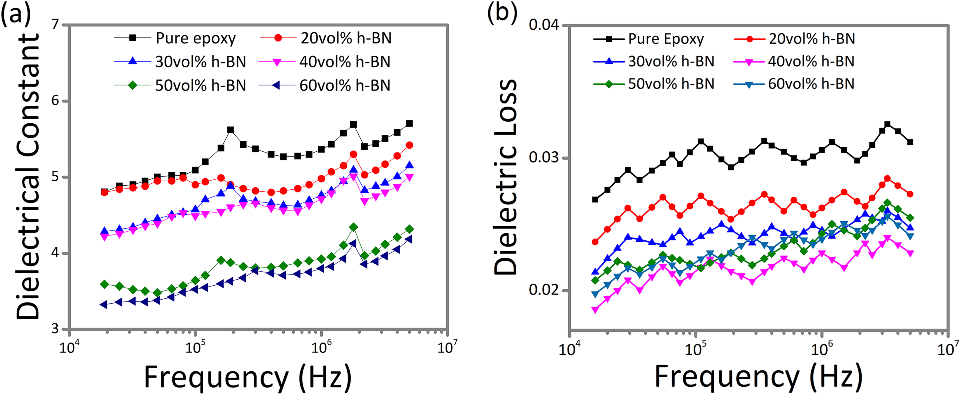
Dielectric properties of the h-BN/epoxy composites as a function of h-BN content (a) dielectric constant and (b) dielectric loss. h-BN: hexagonal boron nitride.
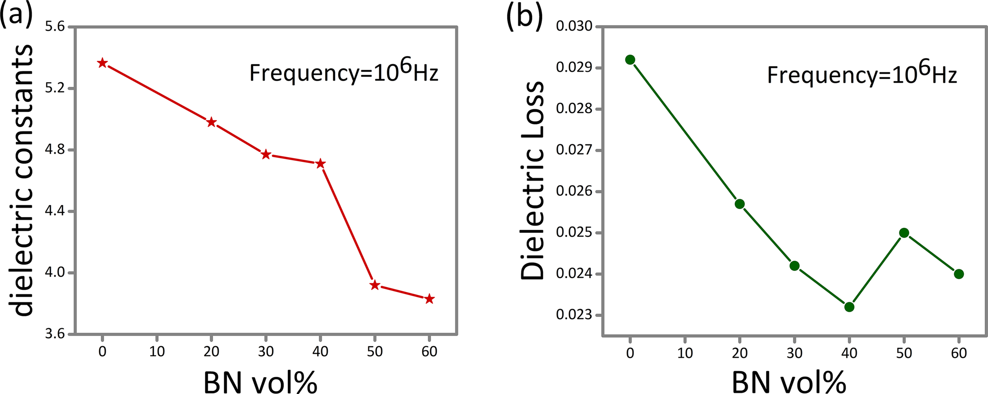
Variation of (a) dielectric constant and (b) dielectric loss of the h-BN/epoxy composites as a function of the filler loading at 106 Hz. h-BN: hexagonal boron nitride.
The curves in Figure 8(b) show the dielectric loss versus frequency from 104 Hz to 107 Hz. The dielectric loss decreases with increased h-BN. It is well known that the dielectric loss is closely related to the electrical conductivity of a composite. 30 Since h-BN has an extremely low electrical conductivity, the decrease in dielectric loss can be ascribed to the embedded insulating h-BN network, which inhibits the mobility of charge carriers.
However, the dielectric loss of the composites increases when the content of h-BN is higher than 40 vol%, as shown in Figure 9(b). This dynamics may be attributed to the defects such as voids and porosity that are introduced into the composites. 7
In addition to the dielectric constant and dielectric loss tangent, the frequency-dependence of dielectric properties is a key parameter for dielectric materials. A weak frequency-dependence can improve the reliability of dielectric materials during operation. 31 Figure 8(a) shows the dependence of the dielectric constant on the frequency for h-BN/epoxy composites. The dielectric constants for the BN/epoxy composites show similar, good stabilities as the pure epoxy resin throughout the whole range of frequencies. Figure 8(b) shows the dependence of dielectric loss on frequency for h-BN/epoxy composites. Compared to the epoxy resin, all the composites possess not only lower dielectric loss but also similar stabilities over the whole range of measured frequencies. In addition, a higher content of h-BN corresponds to a lower and more stable dielectric loss. These results are very attractive for electronic fields because a low and stable dielectric loss is beneficial in reducing power loss and heat production, which can result in increased operating speeds, reduced interference in a circuit, and maintained dimensional stability.
In conclusion, the dielectric analysis results demonstrate that the h-BN/epoxy composites have rather low dielectric constants, low dielectric losses, and weak frequency-dependence in the measured frequency range from 104 Hz to 107 Hz, which shows the great application potential for electronic packaging materials.
Dynamic mechanical analysis
The glass transition temperature (T g) is used to describe the segmental motion of chains in a polymer. DMA is a powerful method to study the T g for polymer materials. The loss factor (tan δ), which is the ratio of the dynamic loss modulus to the dynamic storage modulus, is related to molecular motions and phase transitions in a polymer. 19,25,32 –34 The tan δ curve peaks within the glass transition region when a material changes from a hard glassy to a rubbery state, and this peak corresponds to the T g of the material. The DMA curves in Figure 10(a) show the changes in the tan δ of the composites with various h-BN contents as a function of temperature. Table 1 lists the T g values obtained from the tan δ peaks. The T g values of the composites shift to higher temperatures with increasing contents of h-BN. The variation in T g for the h-BN/epoxy composites indicates that the formation of the 3-D BN network from the filler inhibits the segmental motion of the polymeric chains. 31,35
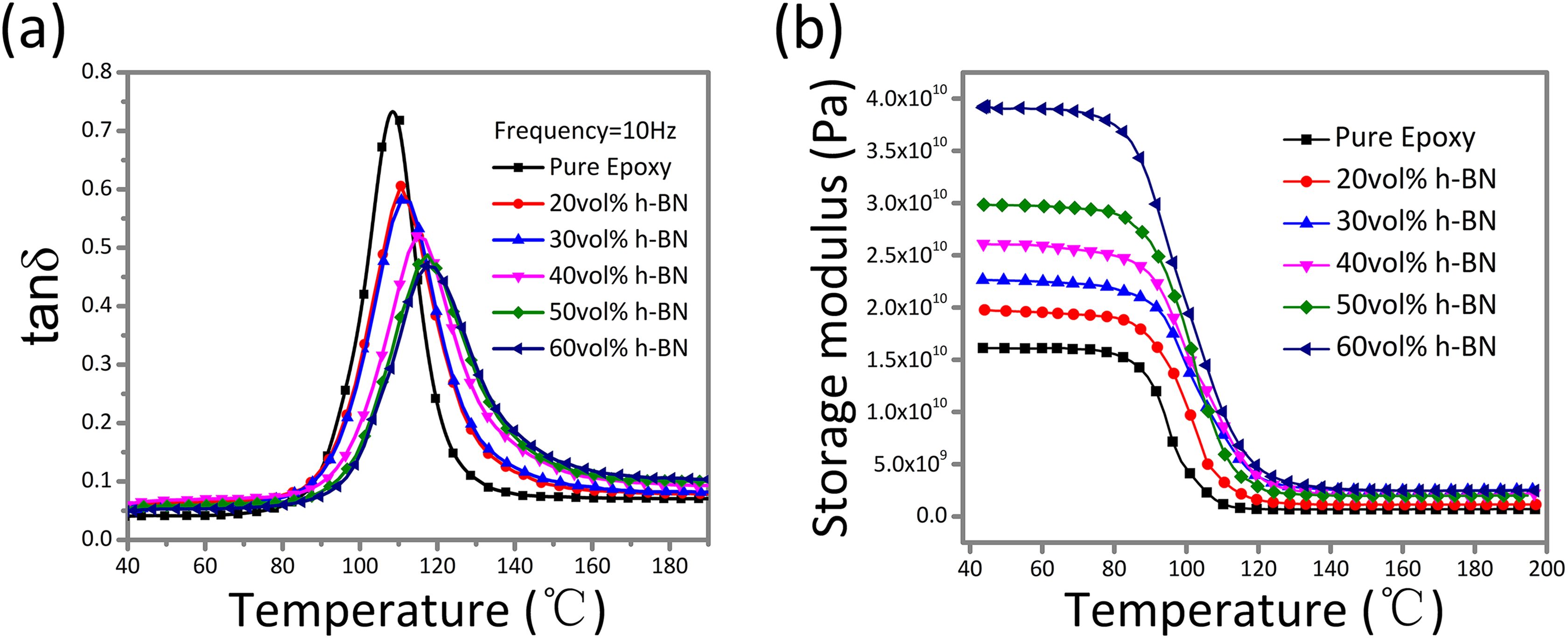
(a) Tan δ and (b) storage modulus versus temperature of the pure epoxy and its composites with different h-BN contents. h-BN: hexagonal boron nitride.
In addition, Table 1 lists the peak heights and half width of the tan δ peaks for the h-BN/epoxy composites with different h-BN contents. Obviously, increasing the h-BN filler reduces the height of the tan δ peak, which further revealed that h-BN is restricting the movement of the epoxy chains and increasing the stiffness of the composites. Meanwhile, the tan δ peak became broader for the h-BN/epoxy composites. Wider peaks indicate a longer relaxation time for molecules, which is caused by decreased movement of the polymeric chains. This may be because the denser 3-D h-BN networks are more effective at hindering the movement of the epoxy chain.
T g values obtained from the tan δ peak, peak heights and half widths of the tan δ curves for the h-BN/epoxy composites.

h-BN: hexagonal boron nitride.
Figure 10(b) shows the storage modulus versus temperature for the pure epoxy and the h-BN/epoxy composites with different h-BN contents. The storage modulus of the h-BN/epoxy composites increases with increasing h-BN. All of the composites exhibit higher moduli than the pure epoxy matrix, and these higher moduli result from the hard-type ceramic fillers that restrict the motion of the epoxy chains. 25 The dense 3-D BN network also increases the stiffness of the h-BN/epoxy composites, as networks with higher densities have higher storage moduli.
Conclusion
In conclusion, continuous 3-D BN network structures were constructed within epoxy composites. The maximum thermal conductivity (40 vol% h-BN) reached 1.98 W mK−1, which was 1000% higher than the pristine epoxy material. In addition, the composites exhibited lower dielectric constants and dielectric losses, better thermal stabilities, and enhanced T g values and storage moduli. The improved thermal conductivities of the BN/epoxy composites can be explained by the construction of 3-D BN networks, wherein BN–BN plates connect with each other to form a relatively dense thermally conductive network. This work provides an effective method for the preparation of polymer composites with excellent performance and is a facile, low-cost, and environmentally friendly approach that could potentially be used in industrial applications.
Footnotes
Declaration of Conflicting Interests
The author(s) declared no potential conflicts of interest with respect to the research, authorship, and/or publication of this article.
Funding
The author(s) disclosed receipt of the following financial support for the research, authorship, and/or publication of this article: This work was supported by the National Key Research and Development Program of China (2017YFB0406200).
