
Abstract
In this work, the surface modification of short carbon fibers (SCFs) using polyimide (PI) as a sizing agent was conducted and fully characterized, and SCF-reinforced polyether ether ketone (PEEK) composites were obtained by extrusion and injection molding. The surface characteristics of the PI-coated SCFs were evaluated using scanning electron microscopy and X-ray photoelectron spectroscopy. The results indicated that a uniform PI sizing layer was formed on the surfaces of the SCFs. Thermogravimetric analysis results demonstrated that PI-coated SCFs had better thermal stability than commercial SCFs. The tensile strength and flexural strength of the PI-coated SCF/PEEK composites showed improvements of 11.8% and 16.6% compared with the commercial cases, which were attributed to the PI sizing treatment effectively improving the interfacial adhesion between the SCF and the PEEK matrix. Dynamic mechanical analysis and the morphologies of tensile fracture surfaces suggested better interfacial adhesion between the fibers and the PEEK matrix, which were in good agreement with the mechanical properties. Due to the convenient processing of PI sizing as well as the effectively improved mechanical properties of the composites, the PI-sizing methodology has great potential application in the field of fiber-reinforced high-temperature engineering plastics composites.
Introduction
Short carbon fiber (SCF)-reinforced thermoplastic composites have been widely used in aerospace, rail transportation, automobiles, sports goods, and other areas due to their high fracture toughness, excellent mechanical properties, and processing repeatability. 1,2 For carbon fiber (CF)-reinforced polymer composites, the mechanical properties of these composites are largely related to the fiber–matrix interfacial adhesion. 3 A strong interfacial adhesion is essential to ensure efficient load transfer from the matrix to fibers, which helps to reduce stress concentrations and improve the mechanical properties. However, the nonpolar surfaces and highly crystallized graphitic structures of pristine CFs lead to poor wettability, weak surface chemical interactions, and low surface energy, which seriously affect the interfacial adhesion in CF/polymer composites. 4 –6
A series of surface treatment methods have been recently explored to improve the fiber–matrix interfacial adhesion, such as electrochemical treatment, 7 high-energy irradiation, 8 chemical grafting, 9 plasma treatment, 10 and sizing agent coating. 11 –14 Most of the surface treatment methods were designed to enhance the chemical bonding between the fibers and polymer resins and to improve the surface roughness of the fiber surfaces. The sizing treatment can prevent the fibers from mechanical damage during the manufacture processing and improve the chemical activity of CFs. 15 –17 Therefore, sizing treatment is the preferred approach to modify the fiber–matrix interface. Common sizing agents for CFs include thermosetting polymers, such as epoxy (EP), polyurethane, and phenol formaldehyde. 18 However, these sizing agents are not appropriate for CF-reinforced PEEK matrix as the sizing layer would be degraded at typical processing temperatures (up to 370°C), which would result in weak interfacial bonding between the CFs and the PEEK matrix. 19,20 Hence, the development of sizing agents with high-temperature resistance and good interfacial adhesion is justified.
Polyimides (PIs) are high-performance materials preferred for their high mechanical properties, thermal stability, and chemical resistance. 21 PI-modified composites possess excellent performance, such as ultrahigh tensile strength, good compatibility, and thermal stability, which makes these composites interesting candidates in aviation, automobiles, sizing, etc. 22,23 Moreover, the PI precursor, polyamic acid (PAA), is soluble in dipolar aprotic solvents, such as N, N-dimethylacetamide (DMAc), N-methylpyrolidinone and N, N-dimethylformamide, and has good wettability with CFs, which makes it applicable in solution processing technologies. PIs as sizing agents have shown potential applications in the field of fiber-reinforced polymer composites. Yuan et al. 24 studied the improved interfacial bonding for CF/polyether sulfone composites through an organic solvent-free PAA sizing. The interfacial shear strength increased from 34 MPa for as-received fibers to 50 MPa for PAA-coated fiber. Giraud et al. 25 reported that the polyetherimide (PEI) sizing improved the interface adhesion between CFs and PEEK, and the continuous interface layer may have consisted of PEI and PEEK. These studies demonstrated that PI could be an appropriate sizing agent to enhance the CF–PEEK interfacial adhesion. However, to the best of our knowledge, PI as a sizing agent to improve the interfacial adhesion between SCFs and PEEK, as well as the mechanical properties of SCF/PEEK composites via extrusion and injection molding techniques have not yet been reported.
In this work, a novel thermoplastic PI polycondensed from bis [4-(3-aminophenoxy) phenyl] (APBP) and 3,3′,4,4′-oxydiphthalic anhydride (ODPA) was employed as a sizing agent to improve the mechanical properties of the SCF/PEEK composites. The SCFs were soaked into PAA solution to coat the surfaces with PAA layers and then the PI-coated SCFs were prepared via thermal imidization. The SCF/PEEK composites specimens were obtained by extrusion and injection molding techniques. Scanning electron microscopy (SEM) and X-ray photoelectron spectroscopy (XPS) were utilized to confirm the surface morphologies and chemical structure of the SCFs, respectively. The effect of PI sizing on the thermal stability of the SCFs was assessed by thermogravimetric analysis (TGA). The influence of the PI-sizing treatment on the tensile and flexural properties of the SCF/PEEK composites was investigated. The interfacial damping of composites was measured by dynamic mechanical analysis (DMA). Furthermore, the morphology of the tensile fracture surfaces was observed by SEM. The surface morphological, thermal, mechanical, and interfacial adhesion properties of PI-coated SCF/PEEK and commercial SCF/PEEK composites are presented, and their differences are discussed in detail.
Experiments
Materials
PEEK resin (melt index: 47 g/10 min) was purchased from Changchun JIDA SEP Co. Ltd. (China). SCFs (10 mm length and 7.1 µm mean diameter, T300) were supplied by GW Compos (China). ODPA (99.9%) was obtained from Sinopharm Chemical Reagent Co. Ltd. (China). APBP (99.0%) was purchased from Changzhou Sunlight Chemical Company (China). DMAc was purified by vacuum distillation over CaH2 and stored over 4 Å molecular sieves prior to use. Other commercially available reagents and solvents were also used without further purification.
Synthesis of the PAA solution and sizing treatment
As depicted in Figure 1, the PAA solution was synthesized from an equal molar ratio of ODPA (6.2043 g, 0.02 mol) and APBP (7.9288 g, 0.02 mol) under nitrogen protection, and a calculated amount of DMAc was added to adjust the solids content to 15%. The resulting mixture was continuously stirred at room temperature for 24 h to obtain viscous a PAA solution. Then, 80 g of the as-prepared PAA solution was diluted with 2.3 kg of DMAc solvent for a working concentration of 0.5 wt% as the sizing agent.
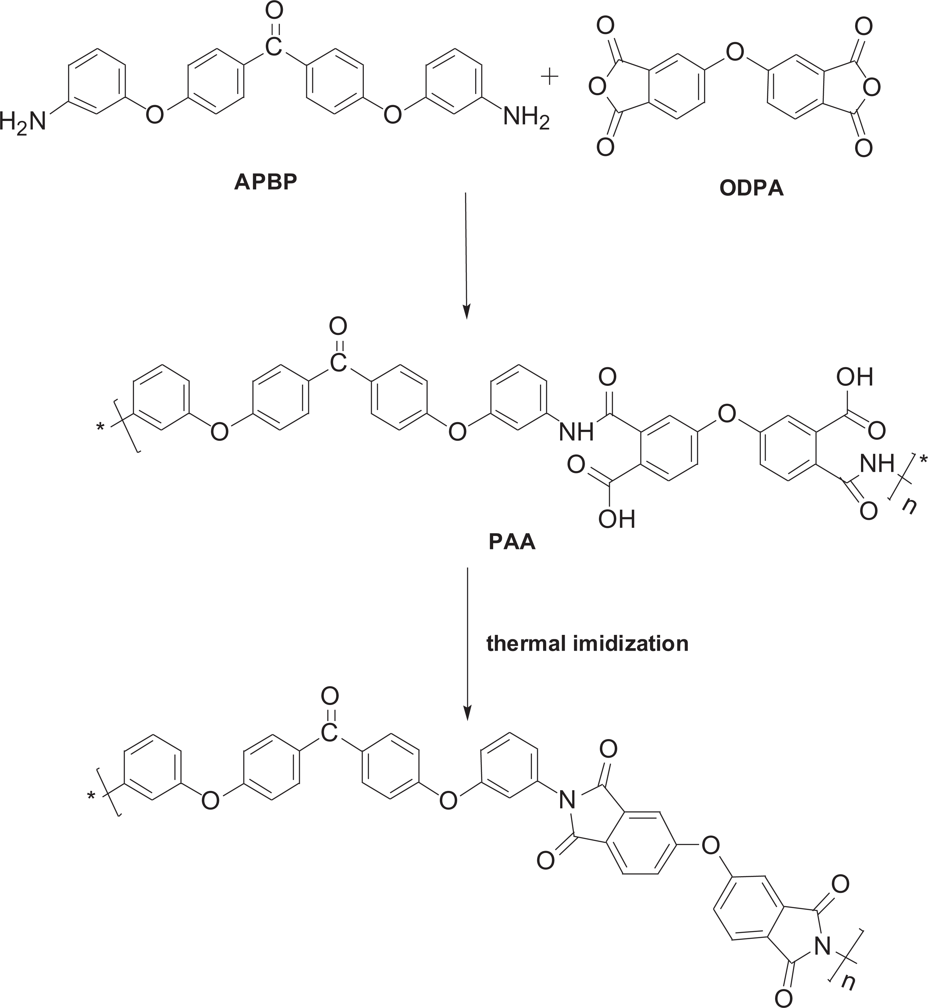
Preparation route of PI. PI: polyimide.
For a better coating, as shown in Figure 2, the sizing agent (main component of EP) coated on the CF was removed first. The CF was refluxed by boiling acetone using Soxhlet extraction for 48 h to ensure that the sizing agent was thoroughly removed. 26 The fiber was cleaned repeatedly with deionized water, then dried under vacuum at 110°C for 2 h to obtain the unsized SCF (named CFT). The sizing treatment of CFs was carried out by a simple coating process. The CFT was first immersed in the PAA solution for 60 s to achieve a uniform coating on the fiber surfaces. Then, the coated fibers were dried at 150°C to remove DMAc. Finally, the PI-coated SCF (named CFM) was obtained by heat imidization under a gradient heating temperature (150°C for 1 h, 180°C for 1 h, 250°C for 1 h, 300°C for 1 h, and 350°C for 1 h) in the vacuum tube furnace. 27 The imidized temperature of PI was determined by Fourier transform infrared spectroscopy (Figure S1, supporting information).
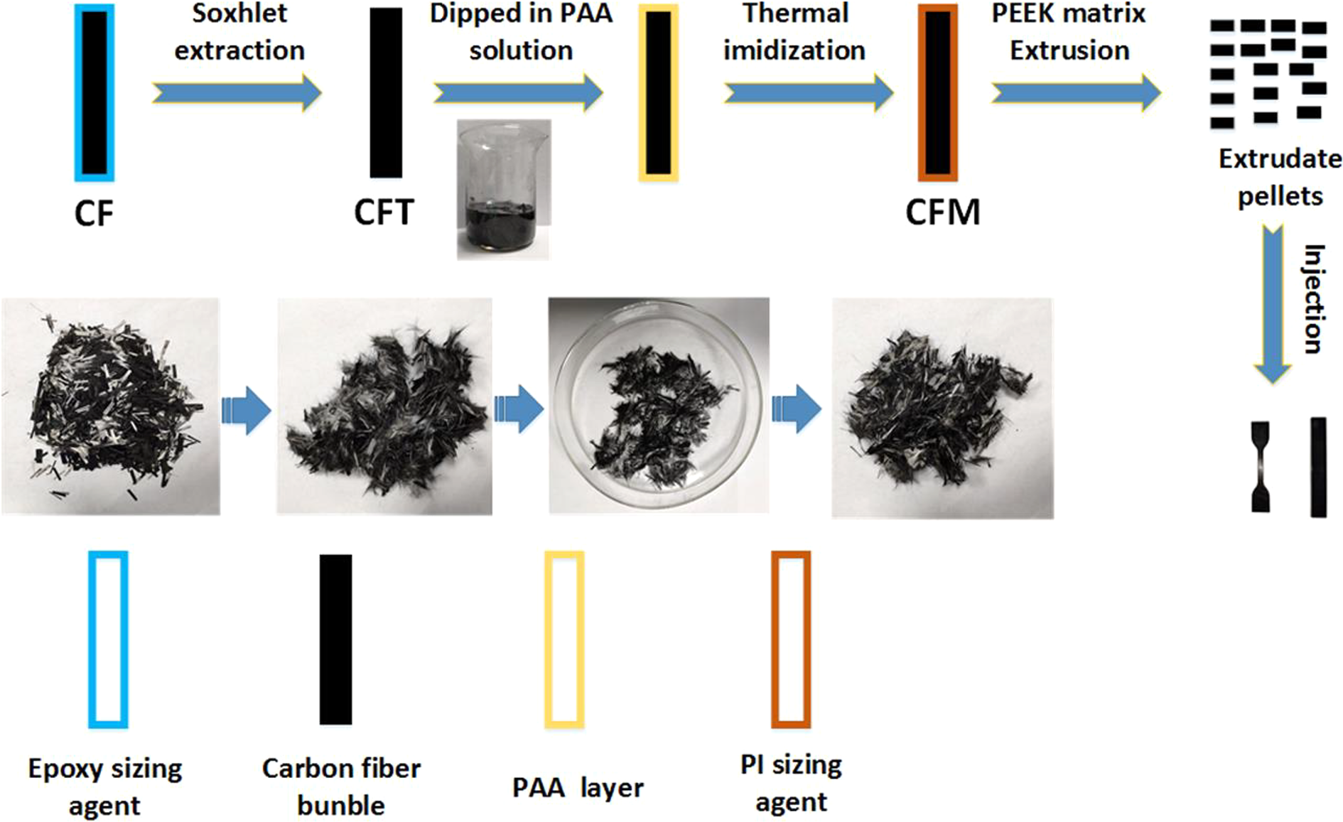
Schematic illustration of the preparation of the modified SCF-reinforced PEEK composites. SCF: short carbon fiber; PEEK: polyether ether ketone.
Preparation of the SCF/PEEK composites
The CFM and PEEK matrices were extruded using a MEDI-22/44 three-screw extruder (Potop Experimental Analysis Instrument Ltd, Guangzhou, China) at 370°C with a screw speed of 180 r min−1, a feed rate of 10 r min−1, and a side feed rate of 8 r min−1. All raw materials were dried at 150°C for 2 h in the oven before the melting process. The as-prepared pellets were dried for 2 h at 150°C prior to injection molding. Standard tensile and flexural test bars were obtained by injection molding at a mold temperature of 220°C and barrel temperature of 360°C using a TY-400 plastic injection molding machine (Tayu Machinery Co. Ltd, China). The content of the CFs in the SCF/PEEK composites was fixed at 8.0 wt%. For comparison, the CF/PEEK and CFT/PEEK composites were also prepared under similar conditions. The physical properties of the composites including density and void content were measured (Table S2, supporting information). The process chart for preparing the CFM/PEEK composites is shown in Figure 2.
Characterization
Surface morphology
SEM (FEI Nova Nano 450, USA) was employed to characterize the microstructure of the SCFs and the tensile fracture surfaces. The samples were first coated with several nanometer-thick gold layer by sputtering and imaged at 15 kV.
X-Ray photoelectron spectroscopy
XPS (ESCALAB 250, USA) was used to characterize the chemical structure of the SCF surface and to validate the presence of PI sizing. Functional groups were assigned by the acquired C1 s chemical shifts and the relative amounts of the groups were evaluated from respective areas of the assumed Gaussian–Lorentzian curves.
Thermogravimetric analysis
TGA was used to evaluate the thermal stability of the SCFs. The analysis was performed by TA 2050 (USA) from 100°C to 800°C with a heating rate of 10°C min−1 in air atmosphere.
Mechanical properties
The tensile and flexural properties were measured on a universal testing machine (Shimadzu AG-I, Japan) under a 20-kN load cell with a speed of 2 mm min−1. The tensile and flexural specimens were prepared according to the standards of ASTM D 638-14 and ASTM D 790-03, respectively. Five samples were tested for each composition. The reported values were the average values and the standard deviations are shown by error bars in the figures.
Dynamic mechanical behavior
DMA was conducted on a TA Instrument Q800 (USA) in three-point bending clamp mode. The storage modulus (E′), loss modulus (E″), and tan δ values of the composites were evaluated at a load frequency of 1 Hz and at a heating rate of 5°C min−1 from 50°C to 225°C. The specimen dimensions were 60 × 10 × 4 mm3.
Results and discussion
Characterization of the PI-coated SCFs
To prove the successful coating of PI on SCFs, the SEM images of CF, CFT, and CFM are shown in Figure 3. Compared to the CF (Figure 3(a) and (b)), the CFT (Figure 3(c) and (d)) presented a relatively smooth surface and a number of longitudinal grooves, indicating that the EP sizing had been already removed. After the sizing treatment, the shallow grooves were filled by PI sizing (Figure 3(e) and (f)). It was clear that the PI layer was tightly attached to the SCF surface. In addition, to further confirm the desizing effect, the water contact angle measurements were carried out (Table S1, supporting information).
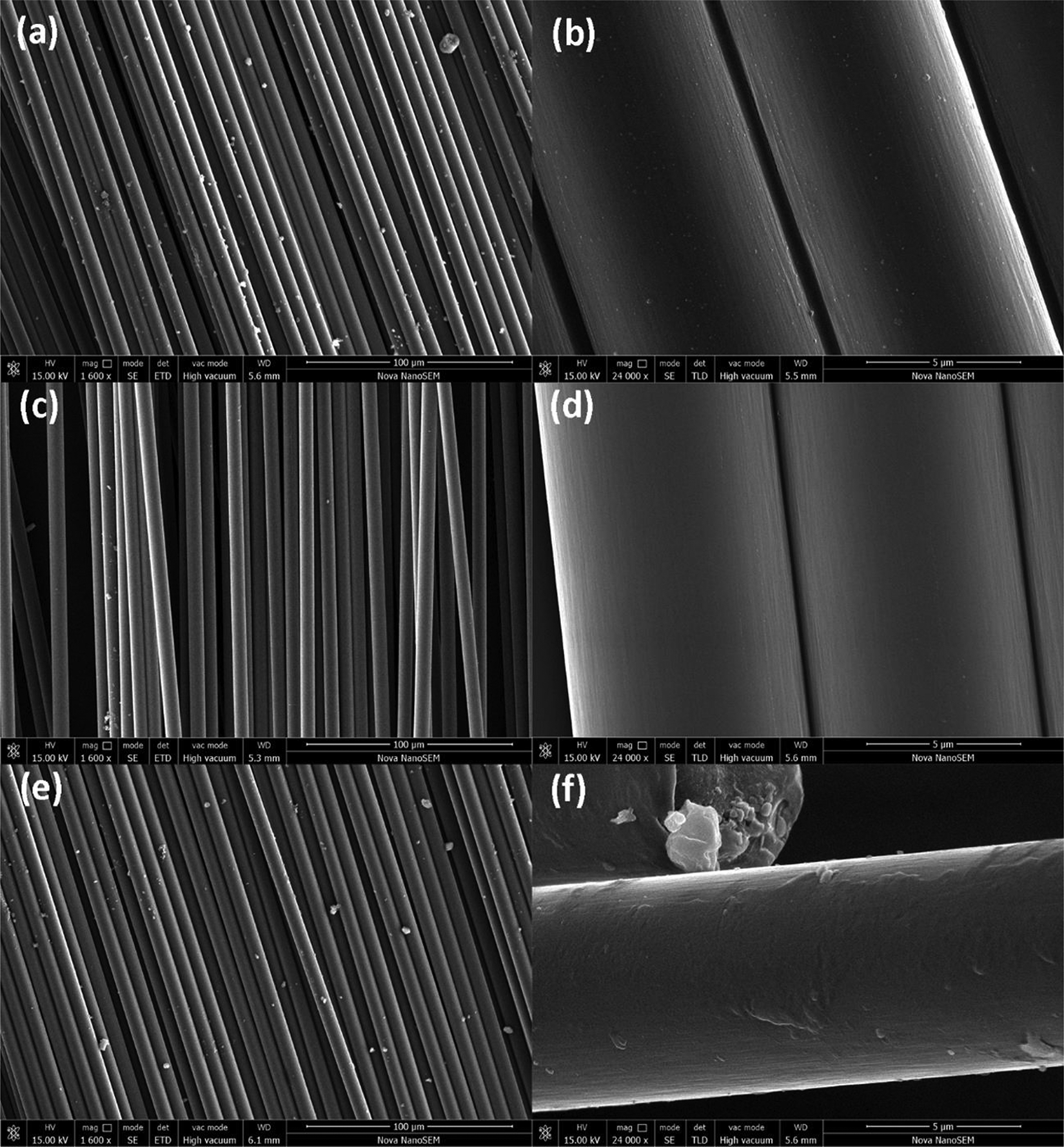
SEM images of CF: (a) and (b) CF, (c) and (d) CFT, and (e) and (f) CFM. SEM: scanning electron microscopy CF: carbon fiber; CFT: unsized SCF; CFM: PI-coated SCF; SCF: short carbon fiber.
XPS was used to evaluate the surface chemical composition of the CF, CFT, and CFM. The values of the atomic concentration are listed in Table 1. The proportion of oxygen to carbon increased from 0.11 for CFT to 0.20 for CFM, indicating that the amount of oxygen-containing functional groups were coated to SCFs after sizing treatment. The nitrogen content of CFT was 2.02%, while the nitrogen content of CFM was 3.03%. The increased nitrogen content can be attributed to nitrogen on the imine ring, which further demonstrated that PI was successfully coated on the SCFs.
XPS results of CFT, CF, and CFM.
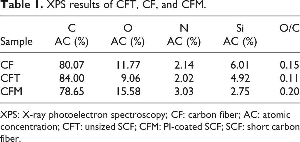
XPS: X-ray photoelectron spectroscopy; CF: carbon fiber; AC: atomic concentration; CFT: unsized SCF; CFM: PI-coated SCF; SCF: short carbon fiber.
Deconvolution of the C1 s peaks for CF, CFT, and CFM are shown in Figure 4. The positions used for the peak fitting are given in Table 2, with the percent contribution calculated from the quantification of the individual components. The C–C and C–O groups were detected on the CF and CFT surfaces, and the difference between these two fibers was the appearance of C=O and benzene ring on the CF surfaces. Furthermore, the presence of the C–N functional group demonstrated that the main component of the sizing agent on CFM was PI. The C1 s peak of CFM was decomposed into five functional groups, which were confirmed as C=O, C–O, C–N, benzene ring, and C–C. 28 Notably, the functional groups of sizing agent on CFM directly affected the interface bonding between fibers and the PEEK matrix.
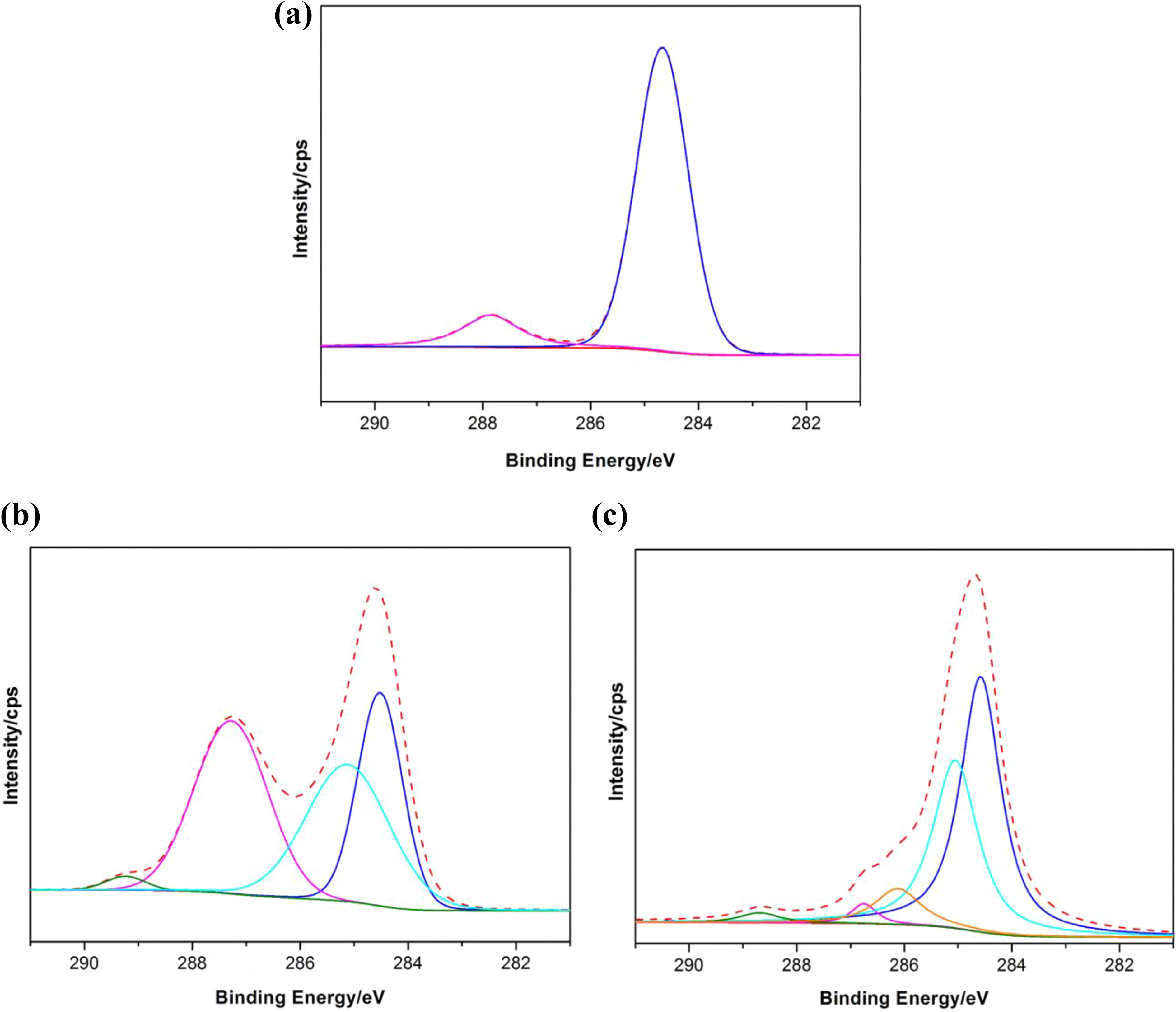
Curve fits of the C1 s photoelectron peaks: (a) CFT, (b) CF, and (c) CFM. CF: carbon fiber; CFT: unsized SCF; CFM: PI-coated SCF; SCF: short carbon fiber.
C1 s peak fit results of CFT, CF, and CFM.
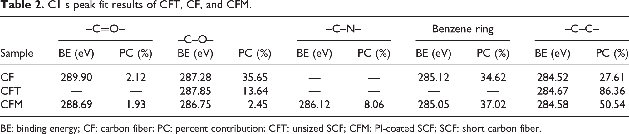
BE: binding energy; CF: carbon fiber; PC: percent contribution; CFT: unsized SCF; CFM: PI-coated SCF; SCF: short carbon fiber.
The sizing agent was designed to increase the interfacial adhesion and bonding of SCF-reinforced PEEK composites and other high-temperature polymer composites, thus the thermal stability of the PI film is a crucial parameter at high processing temperatures. The PI film was prepared by heat imidization of the as-prepared PAA solution cast on a flat glass plate with the same imidization condition, then removed from the glass plate after being immersed in deionized water and dried under vacuum at 80°C for 12 h. As shown in Figure 5(a), the PI film presented high loss temperature in air. The 5% weight loss temperature was 525°C, which was much higher than the processing temperature of PEEK (∼370°C). Additionally, the thermal stability of CFs is also necessary for determining their end use. 29 The TGA curves of CF, CFT, and CFM are presented in Figure 5(b) under air atmosphere and the results are summarized in Table 3. According to the results, the introduction of PI sizing to the SCFs significantly increased the degradation temperature. Compared with commercial CF, the CFM presented high loss temperature and almost had no degradation at the processing temperature of PEEK. The outstanding thermal stability of CFM enabled its use in harsh processing or application conditions.
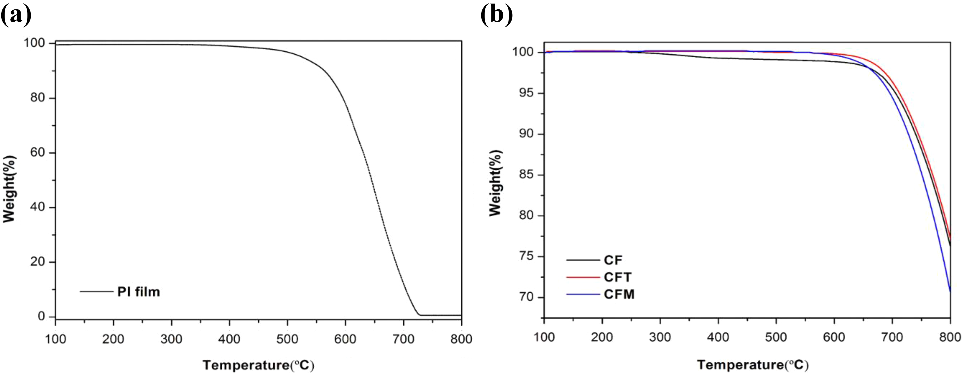
TGA curves of (a) PI film and (b) CF, CFT, and CFM in air atmosphere. TGA: Thermogravimetric analysis; PI: polyimide; CF: carbon fiber; CFT: unsized SCF; CFM: PI-coated SCF; SCF: short carbon fiber.
Thermal properties analyzed by TGA.
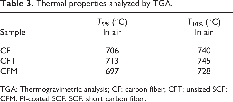
TGA: Thermogravimetric analysis; CF: carbon fiber; CFT: unsized SCF; CFM: PI-coated SCF; SCF: short carbon fiber.
Mechanical properties of the SCF/PEEK composites
The effect of PI sizing on the tensile and flexural properties of the SCF-reinforced PEEK composites was evaluated, and the results are summarized in Table 4. It can be seen from Figure 6(a) that the CF/PEEK composites showed a slightly higher tensile and flexural strength than that of CFT/PEEK composites due to the EP as the sizing agent on CF. However, as shown in Figure 6(a), the tensile strength of the CFM/PEEK composites was 143.6 MPa, corresponding to an increase of 11.8% compared to the CF/PEEK composites with a value of 128.5 MPa. Additionally, the flexural strength of the CFM/PEEK composites (216.7 MPa) was enhanced by 16.6% compared with the CF/PEEK composites (185.8 MPa). The CFM/PEEK composites displayed clear improvements both in tensile and in flexural strength, because strong interfacial adhesion between the SCFs and the PEEK matrix was achieved by the introduction of PI sizing, thereby providing better load transfer from the matrix to fiber. 30 Similarly, Young’s and flexural modulus of the composites were evaluated, and the results are listed in Table 4. As shown in Figure 6(b), compared with the CF/PEEK composites, Young’s modulus and flexural modulus of CFM/PEEK composites exhibited higher values at 5.2 and 8.2 GPa, corresponding to an increase of 15.6% and 26.2%, respectively. The improvements could be attributed to the enhanced interfacial bonding between the SCFs and the PEEK matrix. The final length of fibers in the composites was estimated by SEM to be about 200 µm (Figure S2, supporting information).
Mechanical properties of CF-, CFT-, and CFM-reinforced PEEK composites.

CF: carbon fiber; PEEK: polyether ether ketone; CFT: unsized SCF; CFM: PI-coated SCF; SCF: short carbon fiber.
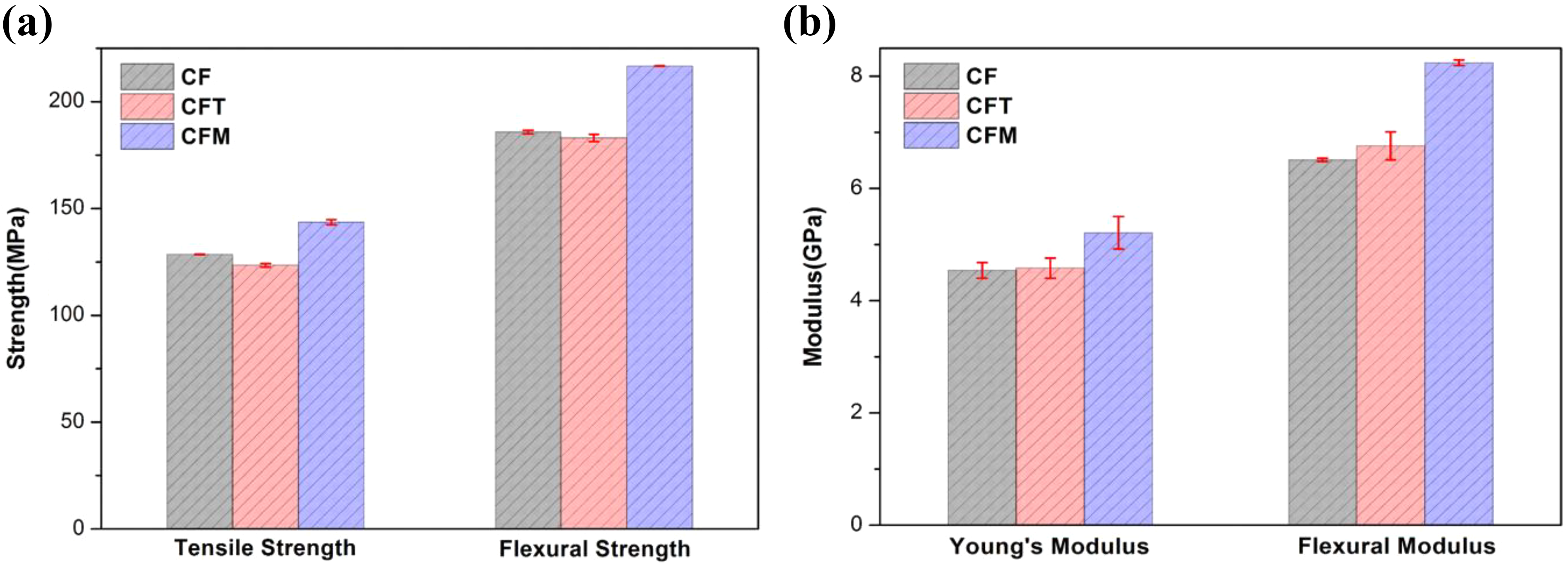
(a) The tensile and flexural strength and (b) Young’s and flexural modulus of CF-, CFT-, and CFM-reinforced PEEK composites. CF: carbon fiber; PEEK: polyether ether ketone; CFT: unsized SCF; CFM: PI-coated SCF; SCF: short carbon fiber.
Micrographs of the tensile fracture surfaces of the SCF/PEEK composites
For the SCF-reinforced polymer composites, the mechanical properties strongly depend on the interfacial adhesion between the fibers and the polymer. To further explain the effect of the PI sizing treatment, the tensile fracture surfaces of the composites were investigated. As shown in Figure 7, pulled-out fibers were clearly observed from the fracture surfaces for the composites. The SEM images of the fracture surfaces of the CF/PEEK and CFT/PEEK composites showed a smooth surface of the pulled-out fibers, and the gaps between the SCFs and the PEEK matrix were quite large (Figure 7(a) to (d)), indicating a relatively weak interfacial adhesion between the SCFs and the PEEK matrix. However, for the CFM/PEEK composites, the gaps between the SCFs and the PEEK matrix disappeared completely (Figure 7(e)) and the amounts of PEEK matrix adhered to the pulled-out CFM surfaces increased (Figure 7(f)). The phenomenon explained that the CFM/PEEK composites possessed better interfacial bonding than the other composites, which can be attributed that the enhanced interfacial compatibility between the CFM and the PEEK matrix that improved the load transfer stress from the matrix to the fibers. Therefore, a strong interfacial adhesion was achieved, leading to the higher tensile and flexural strength of the CFM/PEEK composites.
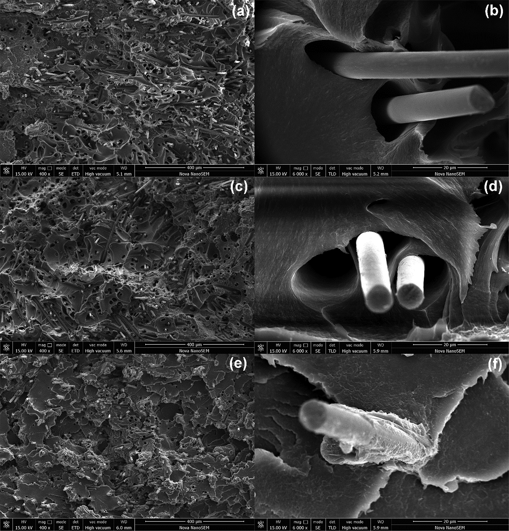
SEM images of the tensile fracture surfaces of (a) and (b) CF/PEEK, (c) and (d) CFT/PEEK, and (e) and (f) CFM/PEEK composites. SEM: scanning electron microscopy; CF: carbon fiber; PEEK: polyether ether ketone; CFT: unsized SCF; CFM: PI-coated SCF; SCF: short carbon fiber.
Dynamic mechanical behavior of the SCF/PEEK composites
DMA was conducted to investigate the storing and dissipation of mechanical energy upon deformation and to evaluate the interfacial adhesion in fiber-reinforced matrix composites. 31 The impacts of PI sizing on the storage modulus, loss modulus, and tan δ of the composites are shown in Figure 8. As shown in Figure 8(a), the storage modulus (E′) of the CFM/PEEK composites was significantly greater than that of the CF/PEEK composites. E′ illustrates the stiffness and elastic response of the composites 32 ; therefore, an improved E′ can be ascribed to a strengthened interfacial interaction between the CFM and the PEEK matrix due to the interface layer of PI sizing. The loss modulus (E″) plots as a function of temperature for the composites are shown in Figure 8(b). It was well known that E″ provides the information of the overall flexibility and the interactions between reinforcement material and matrix of the composites, thus the higher E″ indicates higher damping behavior and greater interfacial interaction. 33,34 The CFM/PEEK composites had the highest E″, which indicated good interfacial interaction and interfacial adhesion between the CFM and the PEEK matrix. Figure 8(c) shows the tan δ for the composites as a function of temperature. Since the damping term tan δ is a genuine indicator of all molecular motions in a given material the magnitude of the damping makes it possible to quantify the interfacial bonding. Strong interfacial interactions between the CFs and PEEK could reduce the mobility of molecular chain at the interface as well as reduce the damping. The glass transition temperature (T g) was defined as the peak temperature of tan δ for composites and the results are listed in Table 5. It can be seen that all these composites exhibit similar T g, which did not change remarkably. Furthermore, the tan δ max at the temperature point T g decrease by 2.2% from 14.19 for bare fiber composites to 13.88 for the composites with PI sizing. The difference can be attributed to the poor interfacial bonding. Furthermore, the introduction of PI sizing has more benefits in improving the interfacial interaction than the commercial sizing.
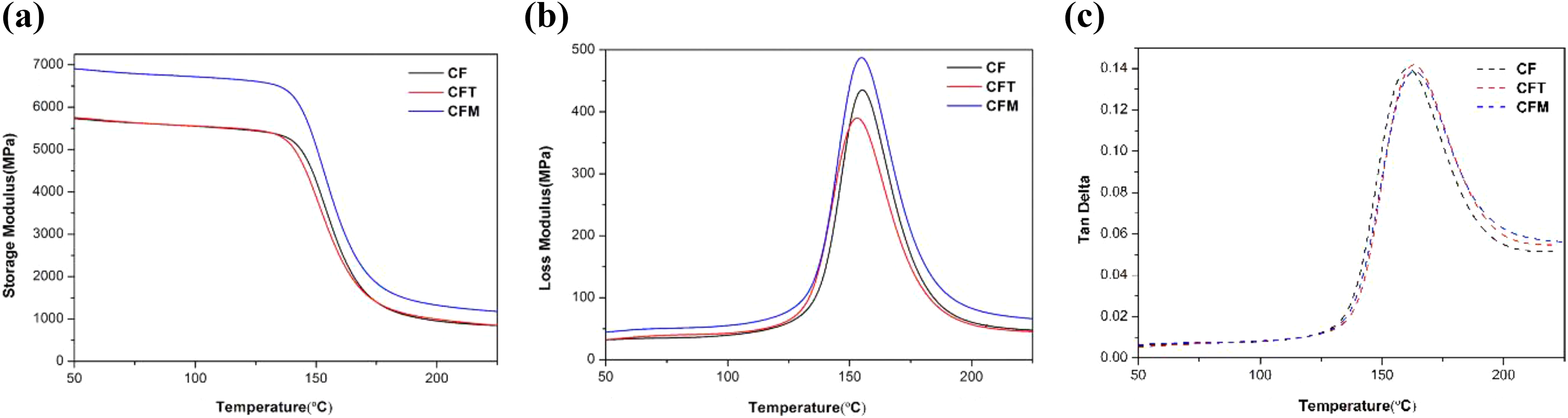
(a) Storage modulus, (b) loss modulus, and (c) tan δ of the CF/PEEK composites, CFT/PEEK composites, and CFM/PEEK composites. CF: carbon fiber; PEEK: polyether ether ketone; CFT: unsized SCF; CFM: PI-coated SCF; SCF: short carbon fiber.
Detailed damping term tan δ analysis of CF/PEEK, CFT/PEEK, and CFM/PEEK composites.
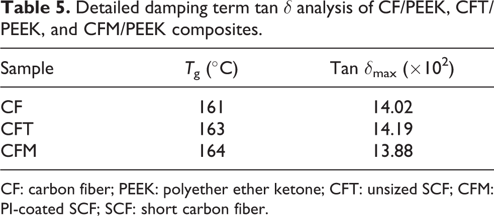
CF: carbon fiber; PEEK: polyether ether ketone; CFT: unsized SCF; CFM: PI-coated SCF; SCF: short carbon fiber.
Conclusions
In summary, the CFM was prepared successfully by introducing PI sizing to the SCF surfaces. The CFT was soaked into the PAA solution to coat as a PAA layer, followed by thermal imidization to obtain CFM. The surface morphology evaluation of CFM demonstrated that the PI sizing was adhered on the SCF surfaces. The XPS results indicated that the main component of the sizing agent on the CFM surfaces was PI sizing. The TGA results illustrated that the CFM had better thermal stability than CF. The modified SCF-reinforced PEEK composites were manufactured using extrusion compounding and injection molding. The tensile strength, flexural strength, Young’s modulus, and flexural modulus of the CFM/PEEK composites showed improvements of 11.8%, 16.6%, 15.6%, and 26.2%, respectively, compared to those of the CF/PEEK composites, which was attributed to the PI-sizing treatment improving the interfacial adhesion between the SCF and the PEEK matrix, and hence improving the mechanical properties. In particular, characterizations, including SEM images of the tensile fracture surfaces and DMA, illustrated that there was better interfacial adhesion between CFM and PEEK. Consequently, PI sizing is a promising surface treatment for enhancing the interfacial and mechanical performance of CF-reinforced high-temperature thermoplastic composites in a production line.
Supplemental material
Supplemental Material, revised_Supporting_Information_(3) - PEEK composites with polyimide sizing SCF as reinforcement: Preparation, characterization, and mechanical properties
Supplemental Material, revised_Supporting_Information_(3) for PEEK composites with polyimide sizing SCF as reinforcement: Preparation, characterization, and mechanical properties by Tao Wang, Yongsheng Jiao, Zhiming Mi, Jiantang Li, Daming Wang, Xiaogang Zhao, Hongwei Zhou and Chunhai Chen in High Performance Polymers
Footnotes
Declaration of conflicting interests
The author(s) declared no potential conflicts of interest with respect to the research, authorship, and/or publication of this article.
Funding
The author(s) received no financial support for the research, authorship, and/or publication of this article.
Supplemental material
Supplemental material for this article is available online.
References
Supplementary Material
Please find the following supplemental material available below.
For Open Access articles published under a Creative Commons License, all supplemental material carries the same license as the article it is associated with.
For non-Open Access articles published, all supplemental material carries a non-exclusive license, and permission requests for re-use of supplemental material or any part of supplemental material shall be sent directly to the copyright owner as specified in the copyright notice associated with the article.