





Abstract
High-performance anti-wear polyetheretherketone/polytetrafluoroethylene (PEEK/PTFE) blends have drawn much attention over the past few years, owing to their wide range of potential applications. However, a convenient and effective method to prepare such blends with superior mechanical and tribological properties is still lacking. In this work, we propose a promising approach that uses melt-processable PTFE (MP PTFE), instead of conventional PTFE, to prepare anti-wear blends. MP PTFE, with melt flow abilities under appropriate conditions, can disperse homogeneously in PEEK, enhancing both the mechanical and tribological properties of the PEEK/PTFE blend. To prove this postulation, in this work, both MP PTFE and commercial PTFE were blended with PEEK, separately, and the effects of PTFE type and content on the tensile and tribological properties of the blends were studied. The results showed that, although the addition of commercial PTFE to PEEK could increase the wear resistance, it decreased the tensile strength of PEEK significantly. Compared to the blends with commercial PTFE, the blends with MP PTFE exhibited better tribological performance and higher tensile strength for PTFE content below 10 wt%. It was confirmed that the better dispersion of MP PTFE in PEEK endowed the blends with higher tensile strength. The surface analysis indicated that the MP PTFE could readily migrate to and enrich the surfaces of the blends. The relatively high PTFE content on the surface favored the formation of tribo-films, enhancing the tribological properties of the blends.
Introduction
Polyetheretherketone (PEEK) is a high-performance engineering plastic with excellent properties such as heat resistance, super balanced mechanical strength, and chemical inertness and is widely used in the medical, 1,2 electronic, 3 aerospace, 4 and automotive industries. 5 Although PEEK has super balanced mechanical strength, its relatively high friction coefficient and insufficient wear resistance limit its application as a tribo-material under heavy-load and high-speed conditions, unless modified. Besides, the low thermal conductivity of PEEK hinders the heat dissipation caused by sliding friction, which may result in melt deformation and even failure of tribo-components when under prolonged continuous friction.
Several modifications were proposed to solve the above problems, such as the addition of thermal conductors to increase the heat dissipation, 6 lubricants to decrease the friction coefficient, 7 inorganic fillers to enhance the hardness, 8 or combinations of these. 9 In the past decades, several researches had focused on the preparation of self-lubricating materials by adding fillers such as graphite, 10 MoS2, 11 and polytetrafluoroethylene (PTFE). 12 PTFE, known for its excellent chemical resistance and low friction coefficient, was reported to exhibit a tribological synergy with PEEK, and the prepared PEEK/PTFE blends demonstrated better tribological properties than neat PEEK. 13 –16 By investigating the effects of PTFE particle size on the tribological behavior of PEEK-based composites, Wang et al. 17 concluded that nano-sized PTFE was more effective than the micro-sized one in enhancing the tribological properties. In addition to the powdery PTFE, expanded PTFE filaments were also used to improve the tribological properties of PEEK, and their wear rates were lower than that obtained when using conventional powdery PTFE. 18 These reports, however, mainly focused on the effect of PTFE on the tribological properties of the PEEK-based blends, and its effects on the mechanical properties of the yielded blends were not reported. Despite this, all these results suggested that the types or physical forms of PTFE affected the tribological properties of the PEEK/PTFE blends. Therefore, an investigation of the effects of the different PTFE types on the tribological properties of PEEK/PTFE blends is significant for establishing an effective preparation technique and developing a new strategy for fabricating wear-resistant PEEK/PTFE blends. To our knowledge, both strength and tribological properties are important for the applicability of PEEK-based anti-wear blends. Thus, good dispersity of PTFE in the PEEK matrix is essential for the practical use of the produced blends. Owing to the inherent surface inertness and non-melt-processability of commercial PTFE, the modification of PTFE has become the tightest bottleneck restricting the dispersion of PTFE in the PEEK matrix. Fortunately, some literatures have reported that the properties of PTFE can be adjusted by electron beam irradiation. 19 –22 Moreover, a previous work had proved that the irradiated PTFE had relatively lower molecular weight, smaller particle size, and better melt processability under heavy irradiation. 23 During irradiation, a minor amount of oxygen is incorporated into the PTFE structure, 24 which can improve its miscibility with PEEK. This melt-processable PTFE (MP PTFE) is considered to exhibit improved dispersity in the PEEK matrix, which endows the blends with better tensile properties. It has also been predicted that MP PTFE with melt fluidity and inherently low surface energy can migrate easily to the outer surfaces of the blends during injection molding, which offers the blends good tribological properties. Therefore, MP PTFE may be conducive to enhancing both the tribological properties and tensile strength of the PEEK/PTFE blends.
In this work, a set of blends were prepared by blending PTFE with PEEK. The tensile strength, friction, and wear properties of the blends were investigated using several techniques. The results showed that the blends with MP PTFE had better comprehensive properties than those with non-MP PTFE. The origin of the differences was discussed, along with the results of structural analysis, and finally, the tribological mechanisms of the blends were elucidated.
Experimental section
Materials
Powdery PEEK (Code 150) was obtained from Changchun Jida High-tech New Material Co., Ltd (P. R. China) and PTFE (Code FR002A) was obtained from Shanghai 3F New Materials Co., Ltd (P. R. China). The PTFE was irradiated according to the procedures detailed in a previous work. 23 The PTFE samples were labelled as PTFE0, PTFE0.5, PTFE3, and PTFE6, in accordance with the irradiation doses (MGy), and their physical parameters are listed in Table 1. PTFE0.5, PTFE3, and PTFE6 were MP PTFE, as indicated by the results of the melt flow rate (MFR) measurements, and PTFE0 was a non-MP PTFE. The PEEK and all PTFE samples were dried at 120°C for 6 h before use.
Physical parameters of PTFE samples used in the experiment.

PTFE: polytetrafluoroethylene; MFR: melt flow rate; DSC: differential scanning calorimetry.
a Determined using a laser particle analyzer.
b Peak temperature of DSC scan at a heating rate of 10°C min−1.
c Detected at 327°C under 5 kg load using a die diameter of 2.1 mm.
Blending PEEK with PTFE
The PEEK was premixed mechanically with different amounts of PTFE in a chamber and then melt-mixed on a SJZS-10A twin-screw extruder (Wuhan Ruiming Plastic Machinery Co., Ltd, P. R. China) operated at a screw rotation speed of 40 r min−1 for 5 min. The barrel temperatures of the four zones were set at 345, 345, 365, and 367°C, respectively, along the extrusion direction. After melt blending, the contents were injected out of the machine to produce the PEEK/PTFE blends.
The test specimens of the blends were injection molded on an SZS-20 injection molding machine (Wuhan Ruiming Plastic Machinery Co., Ltd) at a barrel temperature of 380°C and mold temperature of 160°C. During injection molding, the injection pressure was set to 0.5 MPa for a pressure holding time of 60 s.
Characterization methods and property measurements
The tensile test was performed using an Instron 3366 universal testing machine (Canton, MA, USA) with a crosshead speed of 20 mm min−1, according to the GB/T 1040.1-2006 standard. At least five specimens of each sample were tested.
The friction and wear tests were performed using an M-200 friction and wear tester (Beijing Guance Testing Instrument Co., Ltd, China), according to the GB/T 3960-2016 standard. The specimens were first cleaned with ethanol and then tested at a rotation speed of 200 r min−1 under a load of 200 N at 25°C. To control the mean roughness of the friction pairs, the surface of the steel ring was abraded to a roughness below 0.4 μm, using 320# metallographic sandpaper, followed by a thorough cleaning with ethanol.
By determining the variation of friction torque, the transient friction coefficient was calculated using the following equation:

where μ is the transient friction coefficient, M represents the transient friction torque (N mm), R is the radius of the steel ring (mm), and F is the load applied on the samples (N). By measuring the worn scar width of the specimen with a precision vernier caliper (accuracy 0.01 mm), the wear volume V (mm3) was calculated using the following equation:

where d represents the width of the specimen (mm), R is the radius of the steel ring (mm), and b is the width of the worn scar (mm). Using the calculated wear volume, the volume wear rate (Wv, mm3 s−1) was calculated from the following equation:

where ΔV represents the worn volume (mm3) and Δt represents the sliding time (s). In our experiments, at least three samples were used in each test.
The morphologies of the worn scar surface were observed using an SU3500 scanning electron microscope (SEM; Hitachi, Japan) equipped with an energy dispersive X-ray spectrometer (EDS; Oxford Instrument, UK). The SEM observations were conducted with an acceleration voltage of 15 kV and the EDS measurements used an acceleration voltage of 20 kV.
The SEM images and EDS mappings of the cryo-fractured surfaces of the blends were measured using an Apreo S SEM (Thermo Fisher Scientific, Waltham, MA, USA) equipped with EDS (Oxford Instrument).
The 3-D atomic force microscope (AFM) images were observed using an SPA-400 AFM (Hitachi, Japan).
The water contact angles (WCA) were measured using a TY-82A contact angle goniometer (Chengde Dingsheng Testing Equipment Co., Ltd, P. R. China) under ambient temperature (approximately 25°C). The average WCA value of each sample was obtained after measuring the sample at five different sites.
Results and discussion
Tensile strength
Figure 1 illustrates the effects of the PTFE type and content on the tensile strength of the PEEK/PTFE blends. The results show that the tensile strength of the PEEK/PTFE blends is affected significantly by the type of PTFE. Blends with MP PTFE have higher tensile strength than those with PTFE0, for the same PTFE content. For example, the tensile strengths of the PEEK/PTFE blends from all MP PTFE samples were higher than 100 MPa and approximately 10 MPa greater than that of the PEEK/PTFE0 at 5 wt% PTFE content.

Tensile strengths of PEEK/PTFE blends. PEEK: polyetheretherketone; PTFE: polytetrafluoroethylene.
PTFE is a special polymer with extremely low surface energy, which is often incompatible with non-fluorinated polymers. When mixed directly with non-fluorinated polymers, PTFE tends to agglomerate and produce an immiscible mixture with obvious interfaces. The obvious interfaces are usually the stress-concentrated regions, which lead to a reduction in the tensile strength. In other words, the dispersity of PTFE in non-fluorinated polymers determines the tensile properties of the resultant blends remarkably. With the increase in irradiation doses, the mean particle size of PTFE decreases and its MFR increases (Table 1), suggesting that heavily irradiated PTFE samples would melt and mix with PEEK more homogeneously under heating and screw shearing. This postulation was identified by the SEM and EDS mapping measurements. In Figure 2, the PEEK/PTFE0 blend displays a serious agglomeration of the element fluorine, in the EDS mapping, and the domain of fluorine just corresponds to the PTFE0 in the SEM image. On the contrary, the distributions of fluorine in the blends with MP PTFE are more homogeneous than that in the PEEK/PTFE0 sample, especially, in the PEEK/PTFE6 blend. The synergetic effect of small particle size and high melt fluidity account well for the tensile property differences of the PEEK/PTFE blends. Despite the attractive tensile strength of PEEK/PTFE6, it should be pointed out that the moldings of the PEEK/PTFE6 blends show crazed surfaces under stress, producing undesirable comprehensive performance. For these reasons, the tribological properties of the PEEK/PTFE6 blend are not discussed in the following content.

SEM images and EDS mappings of cryo-fractured surfaces of PEEK/10 wt% PTFE blends: (a) PEEK/PTFE0, (b) PEEK/PTFE0.5, (c) PEEK/PTFE3, and (d) PEEK/PTFE6. SEM: scanning electron microscopy; EDS: energy-dispersive X-ray spectroscopy; PEEK: polyetheretherketone; PTFE: polytetrafluoroethylene.
In addition, the effect of PTFE content on the tensile strength of the PEEK/PTFE blends indicates that the tensile strengths of all the blends decrease with the increase in PTFE content. This decrease can be attributed to the lower tensile strength of PTFE compared to that of PEEK. A similar explanation can also be found in other literatures. 25,26 To retain the tensile strength of PEEK as much as possible, the addition of PTFE should not exceed 10 wt%.
Tribological properties
The tribological properties of neat PEEK were used to evaluate the effect of PTFE on the corresponding properties of the PEEK/PTFE blends. In the tests performed on neat PEEK, detection was performed for approximately 700 s, when a heavy scorched smell was noticed. Figure 3(a) shows that the friction coefficient fluctuated around 0.4 until 400 s, following which it increased continuously to approximately 1.0, by the time the testing was interrupted. During this measurement, the temperature of the steel ring increased monotonously from room temperature to approximately 90°C. The rapid temperature increase of the bulk steel ring surrounded by air in such a short period indicated that an enormous amount of friction heat was generated within a small friction area. Because rapid heat transfer can occur only among the objects with large temperature differences, it can be inferred that the temperature of the polymer side of the friction surface was much higher than that of the steel ring. The heat insulation of polymeric materials can melt or soften the PEEK surface, because of the huge accumulated frictional heat, leading to severe plastic deformation (cf. Figure 3(b)). In extreme cases, the accumulated heat may burn the polymer, producing scorch gases. Therefore, one could reasonably imagine that the melted or softened PEEK would adhere to the rotating steel ring and impede sliding, resulting in a continuous increase in the friction coefficient until the sliding is interrupted. From these results, we postulate that the wear of neat PEEK is mainly in accordance with the adhesive wear mechanism.

Tribological properties of neat PEEK: (a) transient friction coefficient and steel ring temperature versus sliding time and (b) morphology of the worn scar. PEEK: polyetheretherketone.
The friction coefficient of the PEEK/PTFE blends versus sliding time (Figure 4) indicates that the friction coefficients of all the blends are less than 0.5, which means that the tribological properties of PEEK are improved significantly by blending with PTFE. For the PEEK/PTFE0 blends with 5 wt% PTFE0 (Figure 4(a)), obvious friction coefficient fluctuations were observed. With the increase in PTFE0 content, the fluctuations became smaller, and they eventually disappeared when the PTFE0 content increased beyond 15 wt%. The uneven friction coefficient at low PTFE0 contents could also contribute to the partial surface melting or softening of blends during sliding. When the steel ring contacts with the PTFE-predominant domain in the blends, a low friction coefficient is generated, similar to that of PTFE. When the steel ring touches the PEEK-predominant domain in the blends, however, a higher friction coefficient emerges, similar to that of neat PEEK. Consequently, the fluctuation of the friction coefficient in the PEEK/PTFE0 blends at low PTFE0 content can be attributed to the discrete distribution of PTFE0 in the PEEK matrix. When increasing the PTFE0 content in the PEEK/PTFE0 blends, on the other hand, a continuous distribution of PTFE0 may be generated in the PEEK matrix and an even curve appears.

Relationship between the transient friction coefficient and sliding time: (a) PEEK/PTFE0, (b) PEEK/PTFE0.5, and (c) PEEK/PTFE3. PEEK: polyetheretherketone; PTFE: polytetrafluoroethylene.
Unlike the PEEK/PTFE0 blend, the blends with MP PTFE show better tribological properties even if the PTFE content is 5 wt%, as shown in Figures 4(b) and (c). The relatively high friction coefficient at the beginning of sliding is possibly due to the nonstationary contact movement between the steel ring and the specimens, known as the running-in period. Despite this, an even and low friction coefficient is generated and is maintained after approximately 1000 s of testing, implying that the PEEK/PTFE blends with MP PTFE have much lower and steadier friction coefficients than the non-MP ones during the sliding test. When comparing the two MP PTFE materials, PTFE3 appears to be more effective in diminishing the friction coefficient fluctuations of the blends.
Figure 5(a) presents the plots of the average friction coefficients of the blends versus PTFE content, in which the friction coefficients of all the blends decrease with the increase in PTFE content. At PTFE contents below 10 wt%, the friction coefficients of the blends with MP PTFE are apparently lower than that of the non-MP PTFE blends. For instance, at PTFE contents of 5 wt% and 10 wt%, the average friction coefficient of PEEK/PTFE3 was 0.23 and 0.18, respectively, which was lower than that of PEEK/PTFE0 (0.29 and 0.23, respectively). When the PTFE content increased to above 20 wt%, the friction coefficients of all the blends were nearly the same.

(a) Average friction coefficient and (b) wear rate of the PEEK/PTFE blends with different PTFE contents. PEEK: polyetheretherketone; PTFE: polytetrafluoroethylene.
Figure 5(b) shows the wear rates of the blends versus the PTFE content. The wear rate of neat PEEK is approximately 30.7 × 10⁻⁴ mm3 s−1, which is the highest among all the specimens. With the incorporation of PTFE into PEEK, the wear rates of the blends decrease considerably, even for the low PTFE contents. This is because PTFE-based materials can form a tribo-film during sliding, 15 and the formed tribo-film may diminish the wear rate of the materials by alleviating the adhesion between the steel ring and specimen during sliding. The results in Figure 5(b) agree well with the principles, when the PTFE content is below 10 wt%. It can also be observed that the wear rates of all the blends increase with further increase in the PTFE content, which supports the conclusion that PTFE displays a high wear rate despite its low friction coefficient. 27 –29
From the above discussion, we conclude that the PEEK/PTFE blends with MP PTFE have better tribological properties than those with non-MP PTFE, especially, at low PTFE loadings.
Wear mechanism of PEEK/PTFE blends
The SEM image of the worn scar of neat PEEK was presented previously (in Figure 3(b)). The rough striped surface indicates that severe plastic deformation occurred during sliding. On the contrary, the worn scar of the PEEK/PTFE blends (Figure 6) displayed a relatively smooth frictional surface. To get more information about the surface roughness of the worn surface, AFM measurements were carried out and the results are shown in Figure 7 and Table 2. The data in Table 2 show that the surface root mean square roughness of the PEEK/PTFE blends was less than 80 nm, which was much lower than the value of 106 nm, of neat PEEK. The observation suggested that the introduction of PTFE significantly reduced the roughness of the worn surface. The observation could be elucidated on the basis of the inherent features of the PTFE polymer. As a self-lubricating material, PTFE is a relatively soft polymer, which can be peeled off easily under the shear of a steel ring. The PTFE that is peeled off from the blends can then be transferred to and may adhere on to the steel ring to form transfer films during sliding, which effectively releases the direct contact between the specimen and the steel ring. 30 –33 As a result, the transfer film minimizes the roughness of the friction surface, reduces the friction coefficient effectively, and enhances the friction and wear properties of the blends.

SEM images of worn scar: (a) PEEK/10 wt% PTFE0, (b) PEEK/10 wt% PTFE0.5, and (c) PEEK/10 wt% PTFE3. SEM: scanning electron microscopy; PEEK: polyetheretherketone; PTFE: polytetrafluoroethylene.

Three-dimensional AFM images of worn scar surface: (a) neat PEEK, (b) PEEK/10 wt% PTFE0, (c) PEEK/10 wt% PTFE0.5, and (d) PEEK/10 wt% PTFE3. AFM: atomic force microscopy; PEEK: polyetheretherketone; PTFE: polytetrafluoroethylene.
RMS roughness of worn surface.
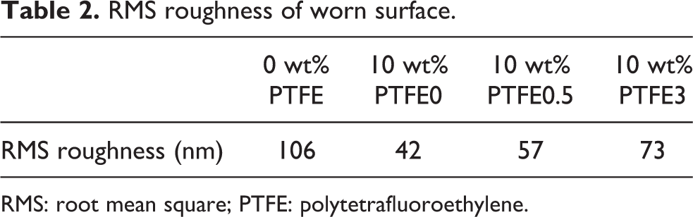
RMS: root mean square; PTFE: polytetrafluoroethylene.
It is known that the tribological properties of a blend are affected mainly by its composition and the structure of the frictional surface. From the above measurements, we noted that the MP PTFE blends had lower average friction coefficients than the non-MP PTFE blends at PTFE contents below 10 wt%. It is possible that there are compositional differences between the surface and the bulk of the blends. To prove this postulation, the fluorine percentages on the surface and in the bulk of the blends were examined by EDS, and the results are summarized in Table 3.
Fluorine content and water contact angle of PEEK/PTFE blends.

PEEK: polyetheretherketone; PTFE: polytetrafluoroethylene.
Table 3 indicates that the surface fluorine content is higher than the bulk content in PEEK/10 wt% PTFE blends. For example, the fluorine content on the surface of the PEEK/PTFE3 blend was 21.19 wt%, which far exceeded the value in the bulk. These results demonstrated that the PTFE could migrate to the surface of the molded specimens during melt processing. As the MFR increased, the migration of PTFE to the surface increased. Although PTFE had the tendency to migrate toward and locate at the surface, preferentially, the migration of high-molecular-weight PTFE (PTFE0) was hindered by the chain entanglements of the macromolecules. On the other hand, MP PTFE with low molecular weight could readily migrate to the outer surfaces during injection molding and enrich the surfaces of the blends. The enriched PTFE on the surfaces of the blends could be responsible for the lower friction coefficient at low PTFE contents.
To prove the migration of PTFE further, WCA measurements were carried out and the results are shown in Figure 8 and Table 3. It was found that the WCAs of PEEK/PTFE blends were higher than that of the neat PEEK. With the increase in MFR, the WCA increased monotonously, which indicated that the migration of PTFE toward the surface became easier. These results were consistent with the findings from EDS measurements. Owing to the migration of MP PTFE during melt processing, the formed surfaces of the blends were enriched with PTFE. This relatively high PTFE content on the surfaces of the blends endowed the blends with outstanding tribological properties.

Water contact angle of PEEK/PTFE blends: (a) neat PEEK, (b) PEEK/10 wt% PTFE0, (c) PEEK/10 wt% PTFE0.5, and (d) PEEK/10 wt% PTFE3. PEEK: polyetheretherketone; PTFE: polytetrafluoroethylene.
Conclusions
The effects of the different PTFE types on the tensile and tribological properties of the PEEK/PTFE blends were investigated comparatively. From the study, the following conclusions could be drawn.
Compared to the commercial PTFE, the blends with MP PTFE exhibited better tribological properties and higher tensile strengths at low PTFE contents.
The uniform dispersion of MP PTFE in PEEK was a key factor affecting the tensile strengths of the blends.
The easier migration of MP PTFE to the surface during processing favored the enhancement of the tribological properties of the PEEK/MP PTFE blends.
To get balanced properties from the PEEK/PTFE blends, the addition of PTFE should not exceed 10 wt%. We are convinced that the presented results would indicate a new strategy for the development of future tribological materials with comprehensive properties.
Footnotes
Declaration of conflicting interests
The author(s) declare no potential conflicts of interest with respect to the research, authorship, and/or publication of this article.
Funding
The author(s) received no financial support for the research, authorship, and/or publication of this article.
