
Abstract
Studies have shown that the construction of a three-dimensional interconnected filler network is an effective method to improve the thermal conductivity of the through-plane under a lower filler load. However, huge challenges still exist in building a long-range layered filler network and reducing the thermal resistance resulting from contact between fillers and matrix. In this work, boron nitride nanosheets (BNNSs) were proposed to be connected with modified cellulose nanofibers (CNFs) to obtain a long-range layered structure filler skeleton by bidirectional freezing orientation. Then epoxy resin was dipped under vacuum condition to prepare composite with thermal conductivity up to 1.43 W/mK in through-plane when filler content is 4.3 vol%, and the composite had low thermal expansion coefficient of 64.1 ppm/°C and excellent volume resistivity up to 3.7 × 10¹² Ω cm at the same time.
Introduction
Devices have been developing toward miniaturization and multi-functionality since the appearance of electronic devices.1–5 In the meanwhile, it shows the trend of high power-density.6–8 To improve the inherently low thermal conductivity of epoxy resin, various fillers are added to matrix, including metal nanoparticles such as Ag, 9 metal oxides such as Al2 O3, 10 metal nitrides such as BN, 11 graphene, and carbon nanotubes (CNT).11–18 Among these fillers, h-BN is considered to be highly suitable material.19–21 When the h-BN powder is peeled off, its thermal conductivity will be significantly advanced.22–24
Although simply using a large amount of boron nitride can tremendously improve thermal conductivity of the epoxy resin, the viscosity of the system will rise sharply under this circumstance.25–28 It makes great negative impact occur on the mechanical properties of the material.29,30 Therefore, it is necessary to explore composites with low filler content and three-dimensional interconnected framework of strong force between the fillers.
In recent years, many studies did research on the construction of a three-dimensional skeleton with high-efficiency heat conduction. For instance, by the salt template method, the hollow boron nitride microbeads/EP are prepared with thermal conductivity reaching 17.62 W/mK (filler loading at 65.6% vol%) 8 ; through an upgraded filtering strategy, an independent and vertically arranged SiCw/f-boron nitride nanosheets (BNNS) frame was established with thermal conductivity of the composite material attaining 4.22 W/mK (through-plane, filler loading at 21.9 vol%) 31 ; under protein foaming technology, the honeycomb structure alumina skeleton was prepared, the thermal conductivity of this composite material hitting 2.58 W/mK (filler loading at 23.32 vol%). 6 Even though the filler framework can achieve an increase in thermal conductivity, the filler content is usually very large. Thermal interface resistances appear in the system as huge number of fillers is introduced; this leaves a serious negative impact on improving the thermal conductivity of the entire system.32–34 Furthermore, the salt template method, protein foaming strategy, and vacuum filtration technology all have the shortcomings of low repeatability 35 and inferior degree of orientation. 36
In this work, improved bidirectional freezing orientation technology was applied to prepare centimeter-level long-range layered structure, which was conductive to establish efficient heat conduction paths and reduce phonon scattering between interfaces. All in all, cellulose nanofibers (CNFs) were introduced into the BNNS/EP system to help build a three-dimensional network that can increase the thermal conductivity to 1.43 W/mK for the through-plane at the filler loading of 4.3 vol%. In addition, the thermal expansion coefficient of the composite material is significantly reduced to 64.1 ppm/°C, lower by 23% compared with 83.5 ppm/°C of pure epoxy resin. Meantime, the composites maintain excellent electrical insulation properties.
Materials and Experiment
The raw materials used in the experiment: commercial hexagonal boron nitride (h-BN, purity > 99.5%, average particle size: 2 μm) was purchased from Dandong Nissin Technology Co., Ltd (China). Isopropyl alcohol (IPA) was provided by Sinopharm Chemical Reagent Co., Ltd. Epoxy resin (EP, JY-257) and modified methyl tetrahydrophthalic anhydride were obtained from Changshu Jiafa Chemical Co., Ltd (China). CNF was purchased from Tianjin WoodeIF biotechnology Co. Ltd. Methyl trimethoxy silane (MTMS) was purchased from Aladdin.
According to the modification method in the previous literature,
37
the process was as follows: MTMS was hydrolyzed under acidic conditions (pH = 4); then, the prepared silane solution was added into the CNF stirring for two hours; finally, the CNFs were frozen and were dried in a freeze dryer (−50°C, 48 pa) for 48 h. Commercial h-BN powders were dispersed into a mixed solvent of IPA and deionized water (1:1). The solution was then sonicated for 8 h. The resulted dispersion was centrifuged successively to obtain exfoliated BNNS. BNNS was further mixed with 10 mL polyvinyl alcohol (PVA) (2 wt%) solution to yield a BNNS/PVA aqueous slurry. Then, it was stirred at 60°C for three hours with CNFs. The obtained suspension was frozen by liquid nitrogen. Then, the composites was freeze‐dried (10 Pa; −50°C) for 48 h. The pre-prepared epoxy resin (epoxy resin: curing agent: accelerator = 10:9:0.1) was poured into the mold after the obtained aerogel had been added. Finally, curing is completed at 90°C for 3 h, 110°C for 2 h, and 150°C for 4 h to obtain 3D composite of boron nitride nanosheets/cellulose nanofibers/epoxy (PBCs) composites (designated as PBCs-x, in which x is content of fillers in the composite) (Figure 1). Schematic of fabrication of CNFs and 3D PBCs-x. Note: PBC: composite of boron nitride nanosheets/cellulose nanofibers/epoxy.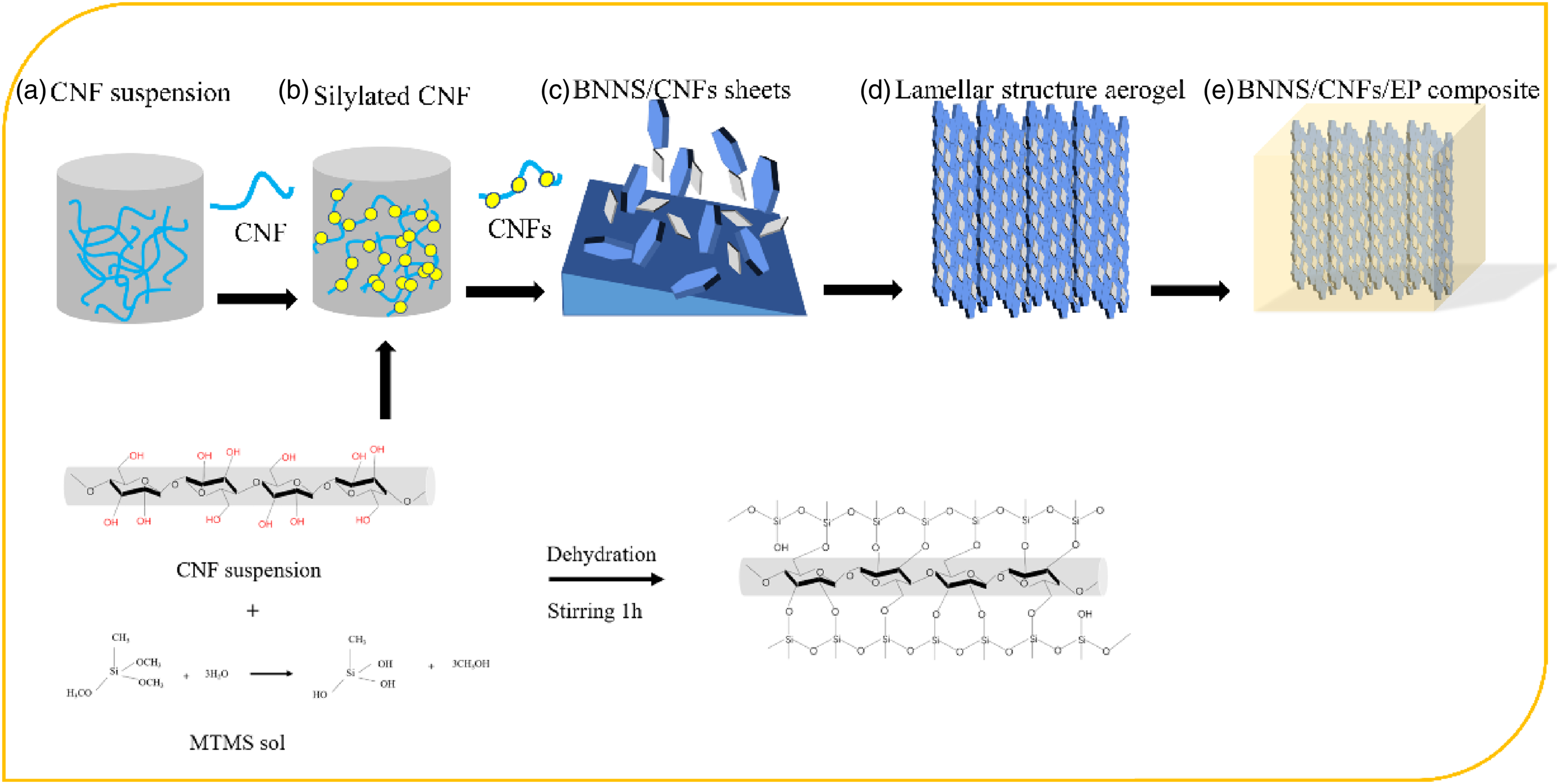
Characterization
The scanning electron microscopy (SEM, Sirion 200 FEI) was applied to examine the morphologies of BNNS and the microstructure of the BNNS network. The morphology of BNNS was further characterized by transmission electron microscope (TEM, JEM-2010, JEOL) and atomic force microscope (AFM, DI Innova, Veeco). X-Ray diffraction (XRD) patterns of BNNS and BNNS/CNFs/Epoxy composites were characterized by a SMARTLAB 9 KW X-ray diffractometer using Cu radiation (k = 0.154 nm) (Kabuskiki kaisha Co., Ltd, Japan). Infrared Spectrum Analysis (PerkinElmer, Spectrum two) was applied to examine the residual functional groups on CNF and CNFs over the wavenumber range of 4000–500 cm−1. Coefficient of thermal expansion (CTE) of the composites in the temperature range from 30 to 120°C was tested using thermomechanical analysis (Q400, TA Instruments). Handheld infrared camera (CEM DT-980, Huashengchang, China) was applied to obtain the data of temperature and thermography. Samples were placed on a homemade heating device. The size of specimen was 25 mm × 25 mm × 5 mm.
Results and discussion
Characterization of BNNS and CNFs
Figure 2(a) shows the morphology of pure h-BN; a typical smooth sheet shape with uneven thickness can be clearly observed. Figure 2(b) shows the morphology of exfoliated BNNSs. It can be seen that their thickness and lateral dimensions were significantly reduced. And the surface chemical compositions on BNNS were characterized by XRD analysis as displayed in Figure 2(e). Apparently, h-BN and BNNS present the same XRD patterns at (002), (100), (101) (102), and (004), respectively. Attributed to the reduction of thickness, peak intensity of BNNS in (002) decrease slightly. Importantly, comparing to pristine BN, a new peak at 27.9° which is due to the (010) B(OH)3 diffraction, emerged on BNNS samples, which indicated the formation of hydroxyl surface groups on the edge of BNNS. From the TEM image of Figure 2(c), one can more clearly see the ultra-thin features of the detached BNNS with great electronic transparency. The high-resolution TEM image further reveals the BNNSs, which is consistent with the well-defined hexagonal diffraction of the lattice recorded by the selected area electron diffraction pattern. The edge counting method showed that the BNNS was composed of 8–10 layers in Figure 2(d). To prove this, AFM was further used to accurately assess the thickness of BNNS. As shown in Figure 2(f) and (g), the thickness of the peeled BNNS can be calculated to be 7–8 nm, which shows the characteristics of several layers of the peeled BNNS. The average lateral size is about 200 nm from Figure 2(g). Characterizations of pure BN and BNNS. (a) SEM morphology of h-BN; (b) SEM morphologies of BNNS; (c) and (d) are the TEM images of BNNS; (e) XRD of h-BN and BNNS; (f) AFM images of BNNS; (g) thickness and size distribution of BNNS; (h) represents the SEM of CNFs aerogel; (i) infrared spectrum of CNF and CNFs. Note: BNNSs: boron nitride nanosheets; SEM: scanning electron microscopy; TEM: transmission electron microscope; XRD: X-Ray diffraction; AFM: atomic force microscope; CNFs: cellulose nanofibers.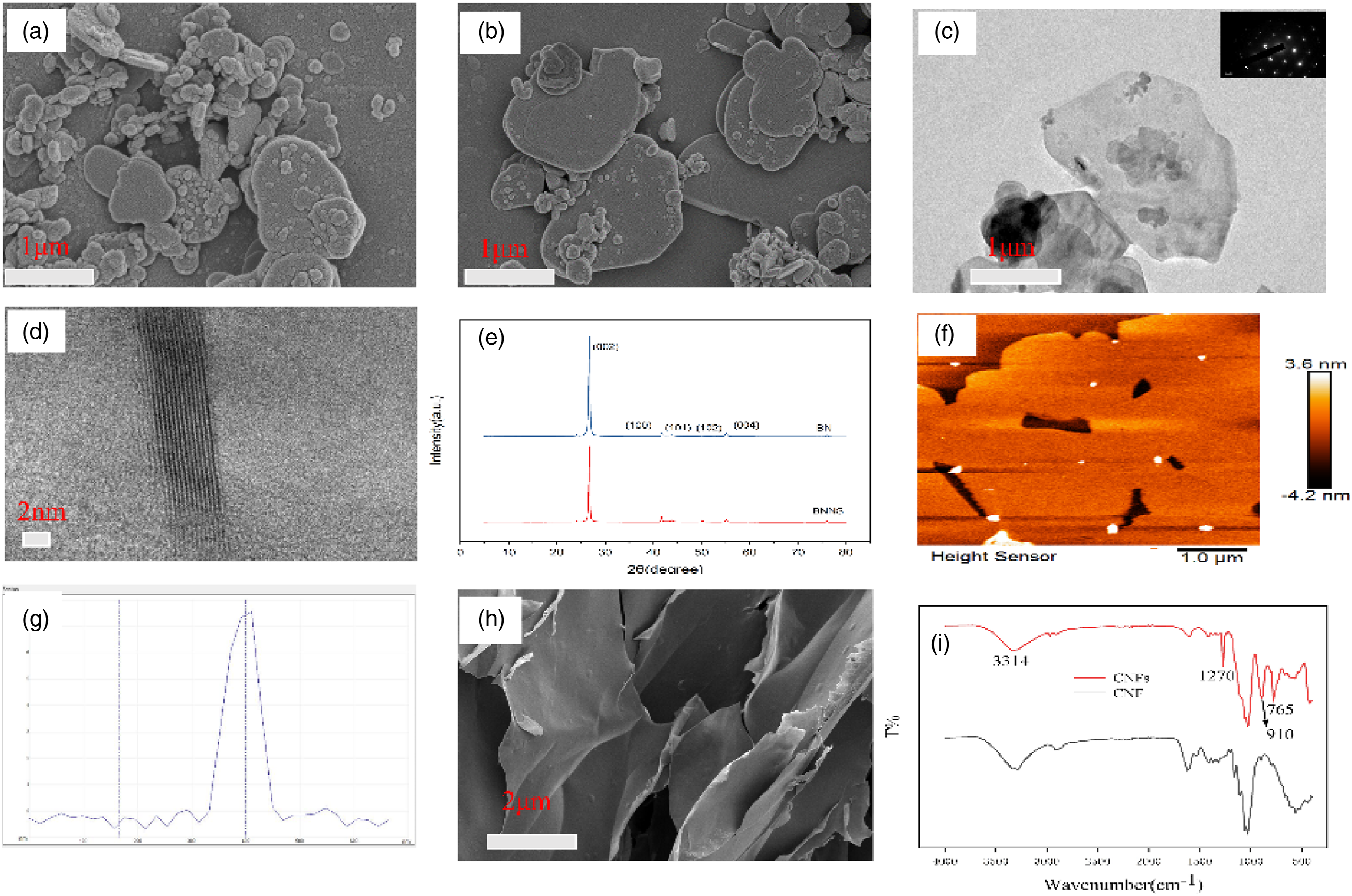
From the Fourier Transform infrared spectroscopy analysis of Figure 2(d), we could verify the successful silylation on the cellulose substrate. Two new peaks at ∼765 and 1270 cm−1 were put down to the characteristic vibrations of the polysiloxan; 38 the intensity of the peak centered at ∼910 cm−1 significantly increased due to the overlapping of new Si-OH stretching peak in polysiloxane and the anomeric C-H deformation;39, 40 a dramatically decrease in peak at ∼3314 cm−1 which represented a stretching vibration of hydroxyl group indicated that the amount of -OH on the pristine CNF had reduced. The silylation essentially affects the microstructure of the aerogel (Figure 2h). In other’s previous work, we could learn that the aerogel of CNF exhibited a distinct three-dimensional porous structure. 41 However, after the modification, we can observe CNFs overlapping together. Therefore, we speculate that the increase of CNF–silanol interaction will reduce the hydrogen bonds in CNF, which may change the shape and growth of CNF network structure. In the conventional freezing stage, solid nucleation occurs randomly throughout the suspension, resulting in structural disorder of the silylated aerogel.
Thermal conductivity
From the SEM, PBCs-x could marvelously maintain a layered network. Moreover, epoxy resin is noticed to finely contact with the BNNS/CNFs layer. When loading fillers, the thermal conductivity (designated as λ) had been significantly improved as λ BNNS/EP < λ BNNS/CNF/EP < λ BNNS/CNFs/EP in the through-plane. This phenomenon can be attributed to the inherent high λ of BNNS and the synergistic effect of BN and CNFs.
Additionally, we can notice that the λ of the bidirectional freezing is much greater than that of the λ of unidirectional freezing. For example, when the filler content is 4.3 vol%, the λ of the bidirectional freezing is 1.43 W/mK, and the λ of unidirectional freezing is only 0.63 W/mK. This is because there are temperature gradients in two directions in the bidirectional freezing, resulting in a layered structure on a larger scale, which formed a more efficient heat conduction path.
In particular, when x is 4.3%, the λ in the in-plane is 1.43 W/mK, which is 550% higher than that of pure resin. Nonetheless, the λ reinforcement of in-plane is obviously insufficient. It can be observed from the cross-sectional views of the PBCs-x in Figure 3(a), (b), (c), and (d). This layered structure leads to a substantial increase of the λ in the through-plane. The growth rate of the through-plane thermal conductivity is significantly faster than that of the in-plane thermal conductivity, which further showed that the filler framework prepared by bidirectional freeze-drying effectively transferred phonons through the high-speed heat conduction path without severe negative scattering. To show the anisotropy of PBCs-x better, we define the anisotropy according to the following formula: (a), (b), (c), (d) cross-section SEM of PBCs-x; (e), (f) λ and enhancement of PBCs-x; (g), (h) λ and enhancement of PBCs-x; (i) anisotropy of PBCs-x; (j), (k) digital photo of aerogel and PBCs-x; (l) elements mapping of PBC-x. Note: SEM: scanning electron microscopy; PBC: composite of boron nitride nanosheets/cellulose nanofibers/epoxy.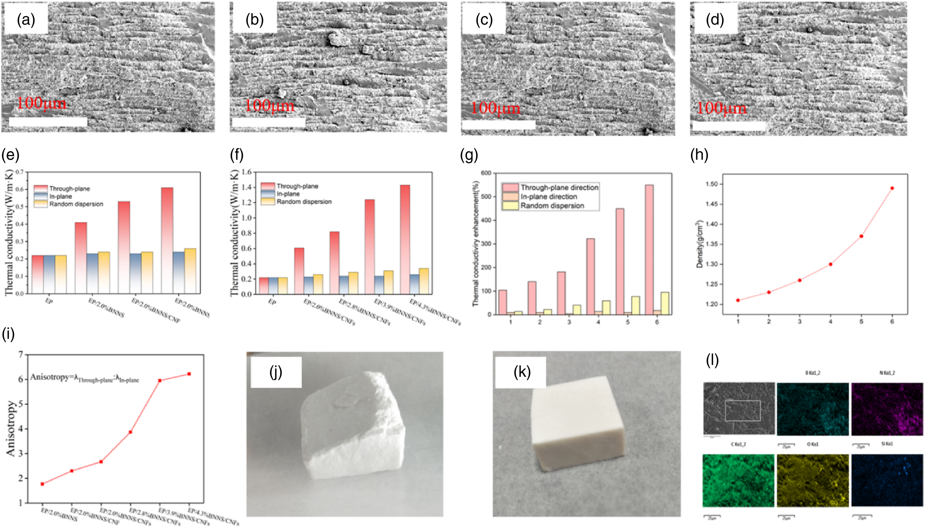
Comparison of through-plane thermal conductivity and enhancement efficiency of 3D PBCs-x with other BN-based polymer composites.
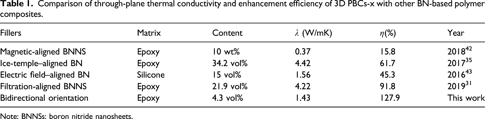
Note: BNNSs: boron nitride nanosheets.
Dimension stability and volume resistivity of PBCs-x
The CTE value of appropriate thermal management materials can reduce thermal residual stress and micro-cracks in electronic equipment, which has been regarded as another key parameter related to the reliability of electronic applications. As shown in Figure 4(a), the embedded 3D BNNS/CNF and BNNS/CNFs framework had a significant inhibitory effect on the epoxy matrix in the through-plane direction because the CTE value of PBCs-x is much lower than that of pure epoxy resin in the glass and rubber state. For example, the CTE value of PBCs-4.3% is as low as 64.1 ppm/°C at 40–60°C and compared to the CTE value of epoxy resin for 83.5 ppm/°C at the same temperature. Even if the test temperature is higher than the glass transition temperature (Tg), the CTE value remains at a low level of 94.6 ppm/°C, which is much lower than the 229.5 ppm/°C of epoxy resin. Due to the restrictive effect of the hybrid filler network on the mobility of the epoxy molecular chain in the z-axis direction, this strongly proves the excellent dimensional stability. More specifically, due to the entanglement between BNNS and CNFs, epoxy molecular chains are constrained in a stubborn co-continuous network. The coupling agent on the BNNS may also limit the movement ability of the matrix segment. (a) Dynamic mechanical curves of PBCs-x in z-axis direction against temperature. (b) Volume resistivity of PBC-x. Note: PBC: composite of boron nitride nanosheets/cellulose nanofibers/epoxy.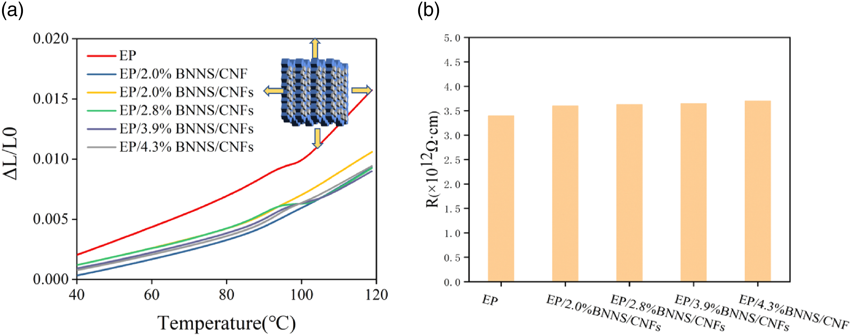
To further characterize the PBC-x composite, volume resistivity was characterized. Figure 4(b) illustrates the volume electrical resistivity (R) of our composites. As BNNS loading increased from 2.0 to 4.3 vol%, the resistivity increased from 3.4 to 3.7 × 10¹² Ω cm accordingly, way above the value of electronic insulator (108–1010 Ω cm). It is noted that thermal interface material (TIM) can be classified into two categories depending on their electrical conductivity. Although TIMs with Ag particles or CNTs have extremely high thermal conductivity, the fillers are usually expensive and the composites are not applicable for many occasions when electrical insulation is mandatory. Alternatively, electrically insulating TIMs such as BN-based composites are highly demanded under such circumstances. In this context, our composite is outstanding for its excellent thermal conductivity, high resistivity, and thermal stability, in addition to its low cost.
Thermal management capability of PBCs-x
Favorable anisotropic thermal conductivity donates composite materials additional thermal management functions. Under certain circumstances, local heat build-up can lead to a rapid increase in temperature, which will cause catastrophic damage to the material. Therefore, it is particularly important to construct an efficient heat conduction path. As a proof of concept, epoxy resin composites were exposed to local heat sources, and all samples were polished to the same size (25 × 25 × 5 mm). Figure 5(a) shows a series of infrared images that reflect the temperature changes on the back of the sample. It is worth mentioning that the anisotropic composite material had not produced noticeable heat storage in the through-plane. Furthermore, the anisotropic composite material greatly hindered the heat diffusion in the in-plane. As there was no obvious heat accumulation, the backside temperature increase was largely changed. We can conclude that in the same composite, the backside temperature gradually rises as time increases. For these composites prepared by unidirectional orientation and bidirectional orientation, the backside temperature of bidirectional composite is always higher than that of unidirectional composite, which is agreed with the difference of thermal conductivity. (a) Demonstration of pure EP, unidirectional orientation and bidirectional PBCs-x as a TIM. (b) The temperature variations of PBCs-x recorded by infrared camera. Note: PBC: composite of boron nitride nanosheets/cellulose nanofibers/epoxy.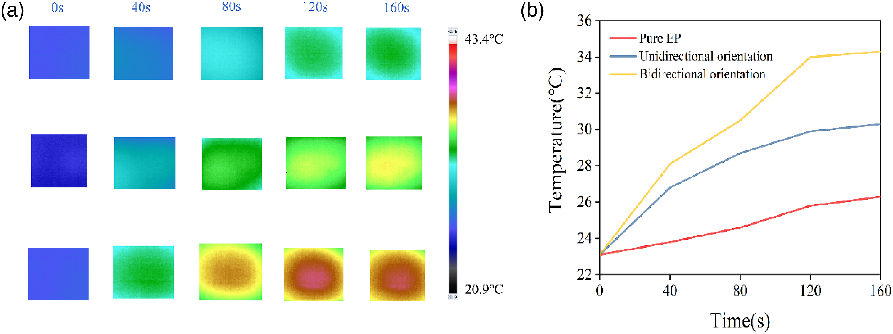
Conclusion
In summary, the long-range layered 3D PBCs-x was successfully constructed by the advanced method of bidirectional freezing. Due to the covalent bonding of the CNFs and the BNNS, the thermal boundary resistance on the phonon transmission path is reduced significantly while the λ of the PBCs-x is improved notably, which is 1.43 W/mK in the through-plane at a low filling level of 4.3 vol% in volume, and has demonstrated excellent heat dissipation capacity in actual tests. In addition, the CTE value of PBCs-x reached as low as 64.1 ppm/°C, lower than the epoxy resin of 83.5 ppm/°C at an extremely low content of fillings, suggesting a significant molecular chain constraint effect due to the highly ordered hybrid filler framework. Furthermore, the composites exhibit excellent electrical insulation properties. All above shows that our research paves the way for realizing high λ composites by designing efficient 3D filler networks. It is of great significance to the development of thermal interface materials.
Footnotes
Declaration of conflicting interests
The author(s) declared no potential conflicts of interest with respect to the research, authorship, and/or publication of this article.
Funding
The author(s) disclosed receipt of the following financial support for the research, authorship, and/or publication of this article: The authors would like to acknowledge the financial support from National Key R&D Program of China (No. 2017YFB0406200), “Strategic Priority Research Program”of the Chinese Academy of Science (No. XDA13040505), Science and Technology Service Network Initiative of the Chinese Academy of Sciences (guide project for innovative and entrepreneurial), KFJ-STS-SCYD-112, Key deployment project of the Chinese Academy of Sciences, KFZD-SW-416, Science and Technology Cooperation Project of Sichuan Province and the Chinese Academy of Sciences, 2017JZ0028, Youth Innovation Promotion Association, CAS (No.2014288), and Major science and technology projects of Anhui Province (No.18030901083).