
Abstract
The prepared mesoporous SBA-15 (Santa Barbara Amorphous-15) was sulfonated and used as filler for the preparation of sulfonated polysulfone based composite electrolyte membranes. The SBA-15 and polysulfone were sulfonated using 3-mercaptopropyl trimethoxysilane and trimethylsilyl chlorosulfonate, respectively. The different weight percentages (1, 3, and 5 wt%) of sulfonated SBA-15 (SSBA-15) were used to prepare composite electrolyte membranes. Water uptake, ion exchange capacity, swelling ratio and proton conductivity of the composite membranes were studied for assessing the suitability of the electrolyte membranes for use in fuel cells. Characterization techniques such as FT-IR, XRD, SEM, TEM and Brunauer–Emmett– Teller were used to study the physico-chemical properties of the electrolyte membranes. TEM and BET analysis showed that SBA -15 retained its mesoporous structure even after sulfonation process. The prepared membranes were then tested in an in-house built single-cell fuel cell using hydrogen as fuel and oxygen as the oxidant. The fuel cell study showed that the presence of Sulfonated SBA-15 in the polymer matrix provided additional ion exchange sites and retained water for proton transfer which resulted in higher power density of 815 mW/cm2 with SPSU + 3% SSBA-15 membrane as compared with Nafion 117®.
Introduction
The depleting non-renewable energy resources and the necessity for generation of power without the emission of toxic gases are important issues that need to be addressed in the current scenario for our fast-growing economy. Fuel cells have emerged as the most promising technology to overcome the energy scarcity over power generation through renewable energy sources.1,2 Fuel cells convert chemical energy into electrical energy through an electrochemical reaction. Among the different types of fuel cells, Proton Exchange Membrane Fuel Cells (PEMFCs) have garnered considerable attention as a promising power source for applications in portable devices, automobiles, and residential power usage.3–5 A conventional fuel cell uses hydrogen as a fuel and oxygen as an oxidant. H2 gas is oxidized at the anode producing H+ ions, which are transported to the cathode through a proton exchange membrane (PEM), while the electrons reach the cathode through the external circuit. O2 gas combines with the H+ ions and electrons to produce water at the cathode.6,7
Proton exchange membranes plays a vital role in determining the fuel cell efficiency. Nafion®, a commercially available electrolyte membrane, is widely used in fuel cells despite its high cost and fluorinated polymer chain. Low-cost, non-fluorinated polymers like PEEK, PSEBS, PSU, PBI, and biopolymers such as chitosan have been studied for their suitability in fuel cells.8,9 To achieve high ion exchange capacity and proton conductivity, several new organic polymer, inorganic polymer, polymer blends, and polymer composite membranes were synthesized and studied.10–14 A functionalized polymer is used as an electrolyte in the fuel cell, and to be an effective electrolyte, it should have several ion-exchange groups, good water retention properties along with good dimensional and thermal stability at high temperatures.15,16
Proton transfer in polymer electrolyte membranes is highly dependent on the number of proton exchange groups and water retention property of the electrolyte membrane. Many electrolyte membranes such as SPEEK, SPEBS, Chitosan, PBI have been tested in fuel cell in an effort to overcome the short-comings of commercial membranes.8,9 However, the problems of limited sulfonation, ion exchange capacity, structural stability, water retention at high temperatures need to be addressed. Polysulfone is gaining popularity because of factors including its wide market availability, minimal environmental effect, outstanding thermo-mechanical resistance qualities, capacity to produce polymeric films, and, its inexpensive cost. Being hydrophobic and having low proton conductivity, Polysulfone, like the majority of the other pristine macromolecules discussed above, must be suitably functionalized by a sulfonation procedure in order to be employed in the fabrication of a PEM. 17 Polysulfone with and without filler material showed comparable fuel cell performance with the Nafion membrane. 18 Without compromising the dimensional stability of electrolytes, efforts were made to achieve high ion exchange capacity and high proton conductivity with good water retention capacity. One such promising method is the incorporation of fillers such as SiO2, TiO2, STiO2 SGO and ZrO2 into polymer electrolyte membranes. These fillers hold water molecules around their structures and favor proton transport.8,9,19–23 Researchers around the world are extensively working on mesoporous materials because of their high surface area, well-defined pore structure, and water retention property which favor proton transfer through their porous structures compared to non-porous inorganic fillers, and also due to their ease of modification, and versatile applications. 24 Among the mesoporous materials, mesoporous silica materials have several advantages such as ease of modification, retention of uniform porous structure, high surface area, and high thermo-mechanical stability. The use of ordered porous structures which hold water molecules favors proton transport through their porous structure.4,25,26 Functionalization of these porous silica materials with sulfonic acid group provides additional hopping sites for proton transfer and water retention, enabling good proton conductivity at high temperatures and poor humidification. With the incorporation of functionalized porous silica material into the polymer matrix, the effectiveness of the polymer electrolyte membranes in fuel cells is increased/improved. 27
In this study, sulfonated polysulfone was synthesized from polysulfone using 3-mercaptopropyl trimethoxysilane reagent followed by mild oxidation. The mesoporous SBA-15 was sulfonated and the mesoporous sulfonated SBA-15 (SSBA-15) is used as the filler material in this study. Being porous and functionalized, the filler material is able to create more ion exchange groups in the polymer matrix and hold water molecules for effective proton transport. Sulfonated polysulfone with different weight percentages (1, 3, and 5 wt%) of sulfonated SBA-15 were used to prepare composite electrolyte membranes and membrane properties such as water uptake, ion exchange capacity, and proton conductivity were studied. The prepared membranes were tested under different temperatures in an in-house built proton exchange membrane fuel cell to understand the fuel Cell performance.
Materials and methods
Materials
Triblock copolymer (P123 = EO20PO70EO20, Mac = 5800), Tetraethyl orthosilicate, Hydrochloric acid, Mercaptopropyl trimethoxysilane, 32% hydrogen peroxide, Polysulfone, Trimethyl silyl chlorosulfonate, 1,2-dichloroethane, N-N dimethylacetamide, and Methanol, Isopropyl alcohol, were procured commercially from sigma Aldrich. The chemicals were used without any further purification and treatment.
Synthesis of SBA-15
SBA-15 was synthesized following the procedure detailed in earlier reports. 28 For the synthesis, a template, triblock copolymer surfactant (P123 = EO20PO70EO20, Mac = 5800) (4.0 g) was dissolved in 30 g of water and 120 g of 2 M HCl solution. Then, TEOS (tetraethylorthosilicate) (8.50 g) was added to the reaction mixture which was stirred for 8 h at 40°C. The resulting mixture was transferred into a Teflon-lined stainless steel autoclave and kept at 100°C for 20 h without stirring. The gel composition of P123: HCl: H2O: TEOS was 0.0168:5.854:162.681:1 in the molar ratio was maintained. After cooling down to room temperature the product was filtered, washed with distilled water, and dried overnight at 60°C. The as-synthesized sample was calcinated at 550°C for 6 h to remove the template. 4
Sulfonation of SBA-15
Sulfonation of SBA -15 was carried out using a post-synthesis grafting method29–31 to get the desired pore structures and degree of sulfonation. In a typical procedure, a mixture of SBA-15 (0.5 g) and 95% 3-mercaptopropyl trimethoxysilane (0.50 mL) in toluene (15 mL) was refluxed at 60°C for 24 h. The resulting thiol-functionalized solid was filtered, washed 3 times with methanol, and dried at 80°C overnight. Thiol groups were converted to -SO3H by mild oxidation of the derivatized thiol functionalized SBA-15 (0.5 g) with 10 mL of 32% hydrogen peroxide by continuous stirring at room temperature for 24 h, which resulted in the formation of Sulfonated SBA-15 with 61% degree of sulfonation.
31
The solid was subsequently filtered, washed three times with methanol, and dried in the oven at 80°C overnight, and then stored in a desiccator for further use (Figure 1). Scheme for the preparation of SSBA-15.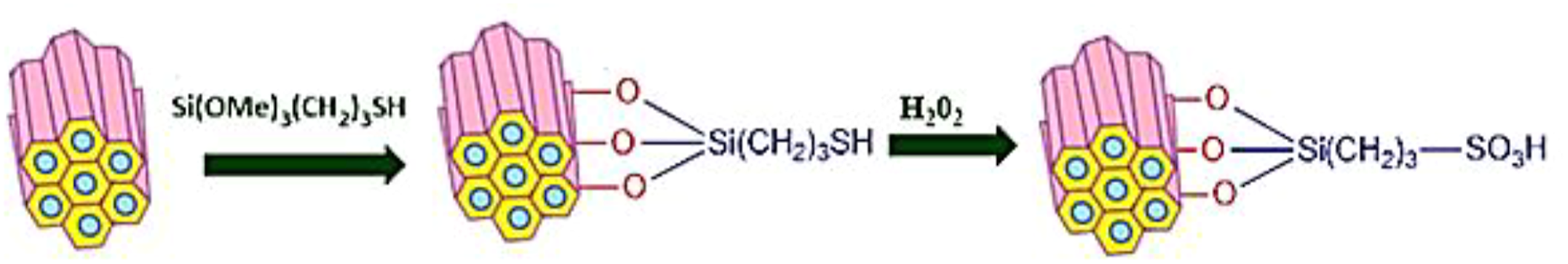
Sulfonation of polysulfone
The scheme for the Sulfonation of polysulfone is given in Figure 2 and is prepared as per the following procedure.1,32 A pre-weighed amount of (5 g) of Polysulfone was dissolved in 30 mL of DCE under constant stirring to get a homogenous polymer solution. To the polymer solution, a mixture of DCE and TMSCS was added dropwise to the above PSU solution. Under constant stirring and in the presence of argon gas, the mixture of DCE and TMSCS was added to the polymer solution. After 24 h of reaction time, the SPSU ionomer was precipitated in freezing isopropyl alcohol, under mechanical agitation. The isopropanol was used to wash the precipitate to remove the residual acid. The ionomer was then dried in a vacuum oven at 60°C for 24 h. Sulfonation of polysulfone.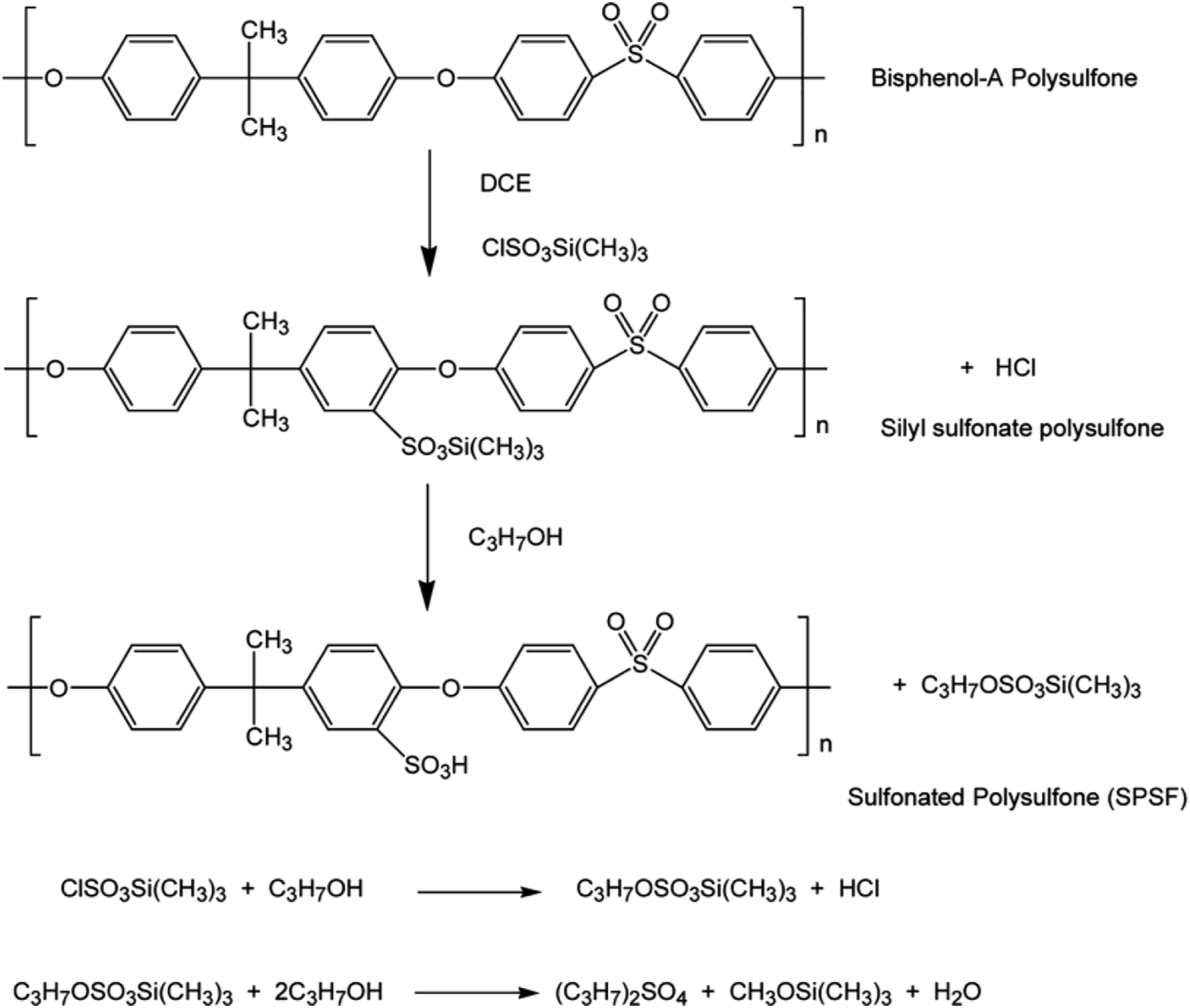
Membrane preparation
The SPSU membrane was prepared by dissolving the obtained SPSU (5 g) ionomer in 20 mL of N-N-dimethylacetamide under constant stirring at 60°C until a homogenous solution was obtained. The homogenous solution was then poured onto a clean dry flat Petri dish in an oven, dried at 60°C for 24 h and then at 80°C for 24 h under vacuum conditions. After the complete removal of the solvent, the membrane was peeled off from the Petri dish.
Composite membrane fabrication
The different weight percentage composite membranes were prepared by the addition of pre-weighed percentages (1%/3%/5%) of SSBA-15 in a fixed quantity (5 g) of SPSU solution. After the addition of SSBA-15, the mixture was mixed well using a magnetic stirrer and ultrasonicated periodically for the uniform distribution of the filler particles in the polymer matrix. The solution was then poured onto a clean dry flat Petri dish, placed in an oven, then dried at 60°C for 24 h and then at 80°C for 48 h. The composite membrane was then peeled off from the Petri dish. Further, to get even thickness, the polymer membranes were hot pressed using polymer press at 75°C for 10 min.
Membrane properties
Water uptake
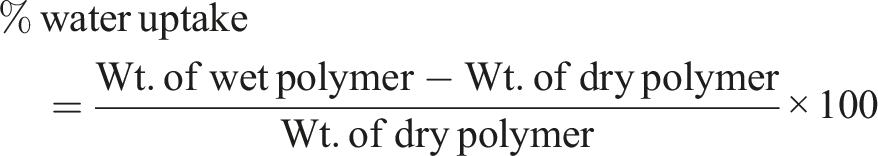
Water uptake by the composite membranes was determined from the difference in the weight of the composite membranes before and after hydration. For all membrane studies, 1 × 1 cm membrane was used. All the membranes were dried well in a hot air oven and then taken for the study. The percentage of water uptake
33
and swelling ratio
34
were calculated using the formulas given below.

Ion exchange capacity (IEC)
Ion exchange capacity is generally determined by a simple volumetric method. The greater the ion exchange capacity, the better will be the proton conductivity of the membrane. Ion exchange capacity is directly dependent on the number of sulfonic acid groups present in the sulfonated polymer. The prepared membranes were soaked in 2 M KCl (Potassium Chloride) solution for 24 h to saturate the membranes and the protons released by the membranes were neutralized by Na2CO3 (sodium carbonate) solution of known concentration with phenolphthalein as an indicator.
35
IEC was calculated by using the formula given below.

Proton conductivity
Proton conductivity of the prepared membranes was studied by the two electrode method using an electrochemical impedance spectrometer (EIS) (Biologics VSP, France). The membranes were sandwiched between two brass rods which were supported on an acrylic plate.
36
A signal of amplitude 10 mV in the frequency range of 1 MHz–100 Hz was applied.

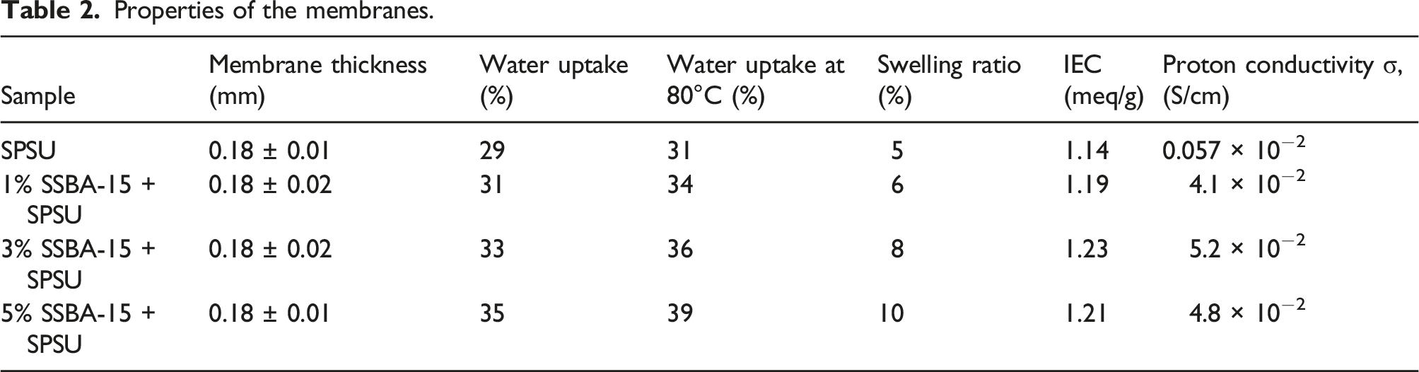
Electrolyte membranes of 1 × 1 cm size were used to study membrane properties such as ion exchange capacity, water uptake, swelling ratio and proton conductivity.33,35 The membrane thickness, ion exchange capacity, water uptake, and proton conductivity of the prepared membranes are listed in Table 2.
Instrumental analysis
The physico-chemical properties of the prepared composite electrolyte were studied by FTIR (AlphaT Bruker Optics) for the presence of functional groups, and XRD (Xpert Pro, Pan Analytical, Siemens diffractometer D5000) to study the crystallinity of the membranes. Surface area, pore size, and specific surface area were studied by Nitrogen adsorption and desorption isotherms were measured by BET (Brunauer–Emmett– Teller) method using Autosorb Automated Gas Sorption System (M/s. Quantachrome, USA) to calculate the average pore size and pore volume of the mesoporous materials. The surface area was calculated by the BET method while pore volume and pore size were calculated by the BJH method. The samples were initially degassed at 200°C for 3 h in a vacuum and liquid N2 was used as the adsorbate. The surface morphology of the membranes was studied using SEM (Zeiss MA 15/EBO18) and TEM (Tecnai T30). 1H-NMR spectrum was recorded at 300 MHz with a Bruker NMR spectrometer to further confirm the sulfonation of Polysulfone.
Membrane electrode assembly preparation and fuel cell performance
The detailed procedure for the fabrication of the membrane electrode assembly (MEA) and fuel cell performance study is as follows. 36 The MEA was fabricated by sandwiching the prepared electrolyte between the two (anode and cathode) electrodes. The electrocatalyst used for PEMFC was 20 wt% Pt/C for both the anode (loading 0.25 mg/cm2) and cathode (loading 0.5 mg/cm2) sides. The catalyst ink was prepared by mixing the catalyst, isopropanol, deionized water, and Nafion solution as the binder and was coated on a carbon cloth. The electrode dimensions were 5 cm × 5 cm (total area, 25 cm2). The MEA was fabricated by hot pressing the anode and cathode onto the membrane at 90°C and 150 kg/cm2 for 3 min.
An in-house built single-cell fuel cell with an active area of 25 cm2 was used for the fuel cell experimental study. 100% relative humidity and 2.5 atm pressure was maintained during the fuel cell operation. With the fabricated MEA, H2 and O2 flow rates (40 mL/min) were maintained in the anode and cathode, respectively. Fuel cell performance was studied at 25°C, 60°C, and 80°C temperatures. 37
Results and discussion
FTIR of SBA-15 and SSBA-15
Figure 3 shows the FTIR spectra of SBA -15, SSBA-15. The observed bands at 1120–1020 cm−1, 1620 cm−1, 920–950 cm−1, 840–790 cm−1, and 460–400 cm−1 in Figure 3(a) correspond to the SiO4 vibration bands, which confirm the presence of terminal OH groups and absorbed water molecules. The band broadening observed between 1000 and 1200 cm−1 was due to the overlapping of -SO3H peaks at 1190 cm−1 and with that of the silica 1036 cm−1 peak. The FT-IR study reveals the sulfonic acid functionalization of mesoporous SBA-15 which is well in agreement with the study by Beyhan Erdem and Cagla Azko.
38
FT-IR spectra of (a) SBA-15 and (b) SSBA-15.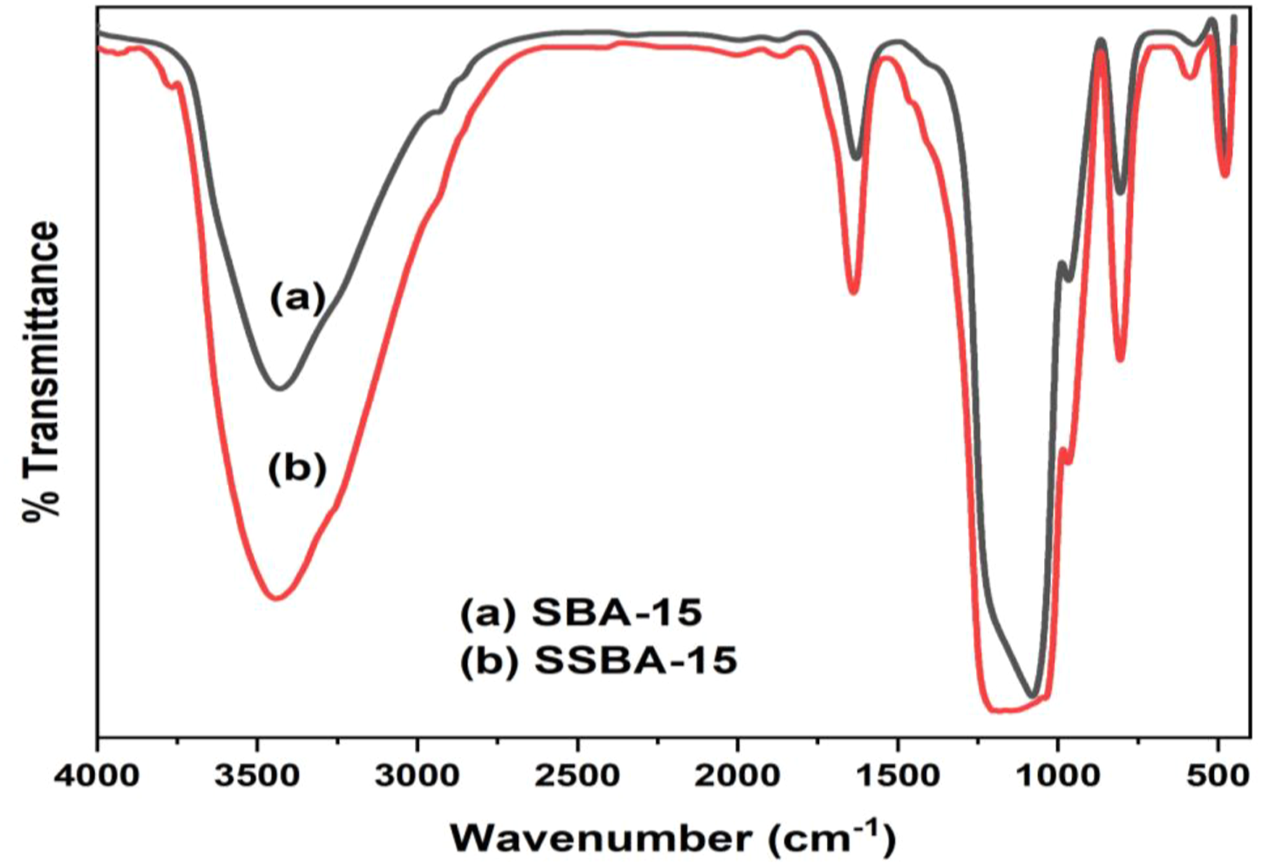
XRD studies
The XRD pattern of the SSBA -15 (Figure 4) material is identical to that of the parent SBA-15, which indicates that the long-range ordering of the material is not affected by the sulfonic acid functionalization. SBA-15 framework is generally amorphous and no significant diffraction peak is observed in wide-angle XRD diffraction.
39
Typical values of SSBA-15 silica that display (100), (110), and (200) reflections in their X-ray diffraction patterns are similar to those of conventional SBA- 15, but with reduced intensity, thus revealing the sulfonic acid functionalization as reported earlier.28,40 XRD patterns of (a) SBA-15 and (b) SSBA-15.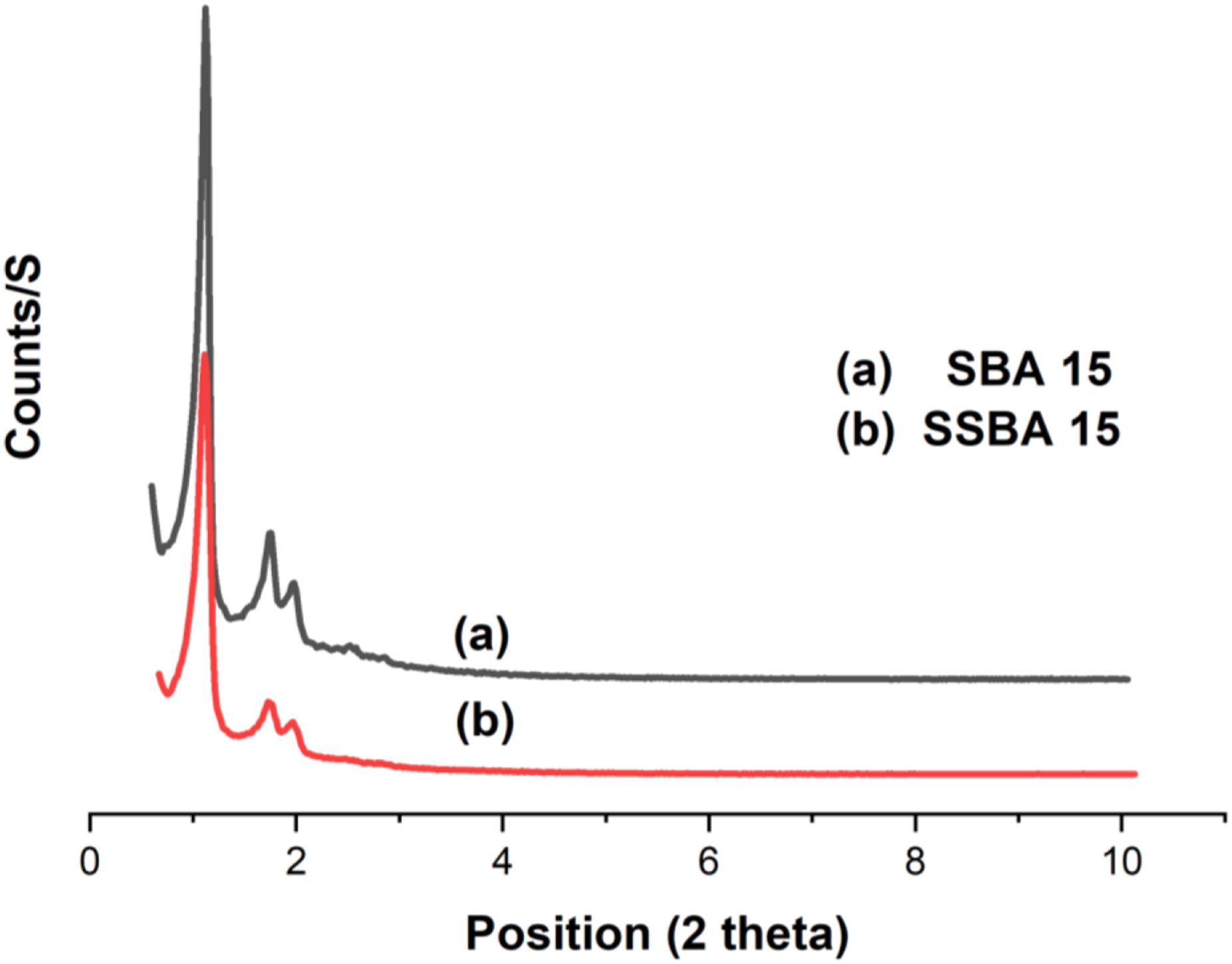
BET analysis
BET analysis showed that the prepared mesoporous SBA-15 and sulfonated SBA 15 (Figure 5) have specific surface areas of 530 and 355 m2/g respectively. The nitrogen adsorption isothermal plot of SSBA-15 has type IV isotherm, which is similar to that of SBA-15.
41
The observed hysteresis loops show that they belong to the same type of pore structures. The variation in pore diameter and pore volume values between SBA-15 and SSBA-15 suggests the versatile cylindrical pore entrances as shown in Table 1. The prepared SBA-15 and SSBA-15 materials with their long channeled and open pore networks are expected to be efficient filler materials for water retention and proton conductivity in fuel cell applications. N2 – adsorption and desorption isotherm of (a) SBA-15 and (b) SSBA-15. Characteristics of SBA – 15 and SSBA - 15.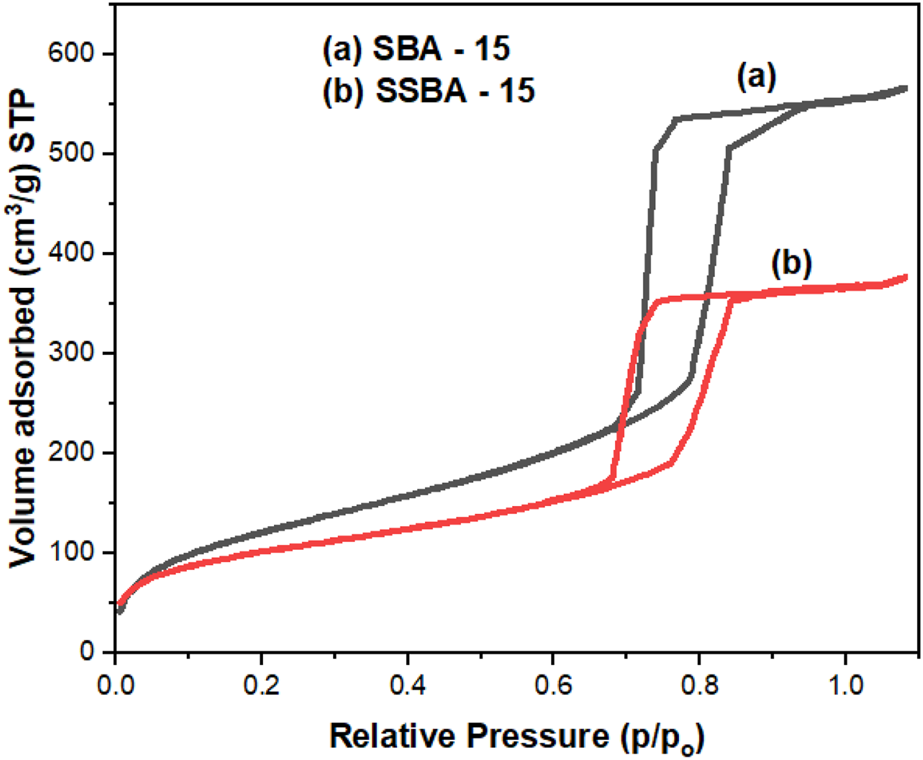

TEM
The morphology of the prepared SBA-15 and SSBA-15 was studied using TEM as shown in Figure 6. The images show that SBA-15 before and after sulfonation retains its unique mesoporous architecture of hexagonally aligned 2D cylindrical channels with excellent textural uniformity.
29
The TEM images exhibit hexagonally aligned mesoporous cylindrical channels in the SBA – 15 and SSBA-15 particles. This unique mesoporous architecture of the SBA – 15 and SSBA-15 particles was also confirmed by conducting XRD measurements. Figure 4 shows that the SSBA-15 particles have three characteristic XRD peaks corresponding to (100), (110), and (200) planes, which are consistent with the results of typical SBA-15 type particles.
31
Hence, the XRD spectrum of the SSBA-15 particles confirms the long-range-ordered mesoporous structure with excellent textural uniformity of hexagonal space groups. However, the pore size of SSBA-15 is reduced as compared to that of SBA-15 due to sulfonation as observed from the Table 1. TEM images of (a) SBA-15 and (b) SSBA-15.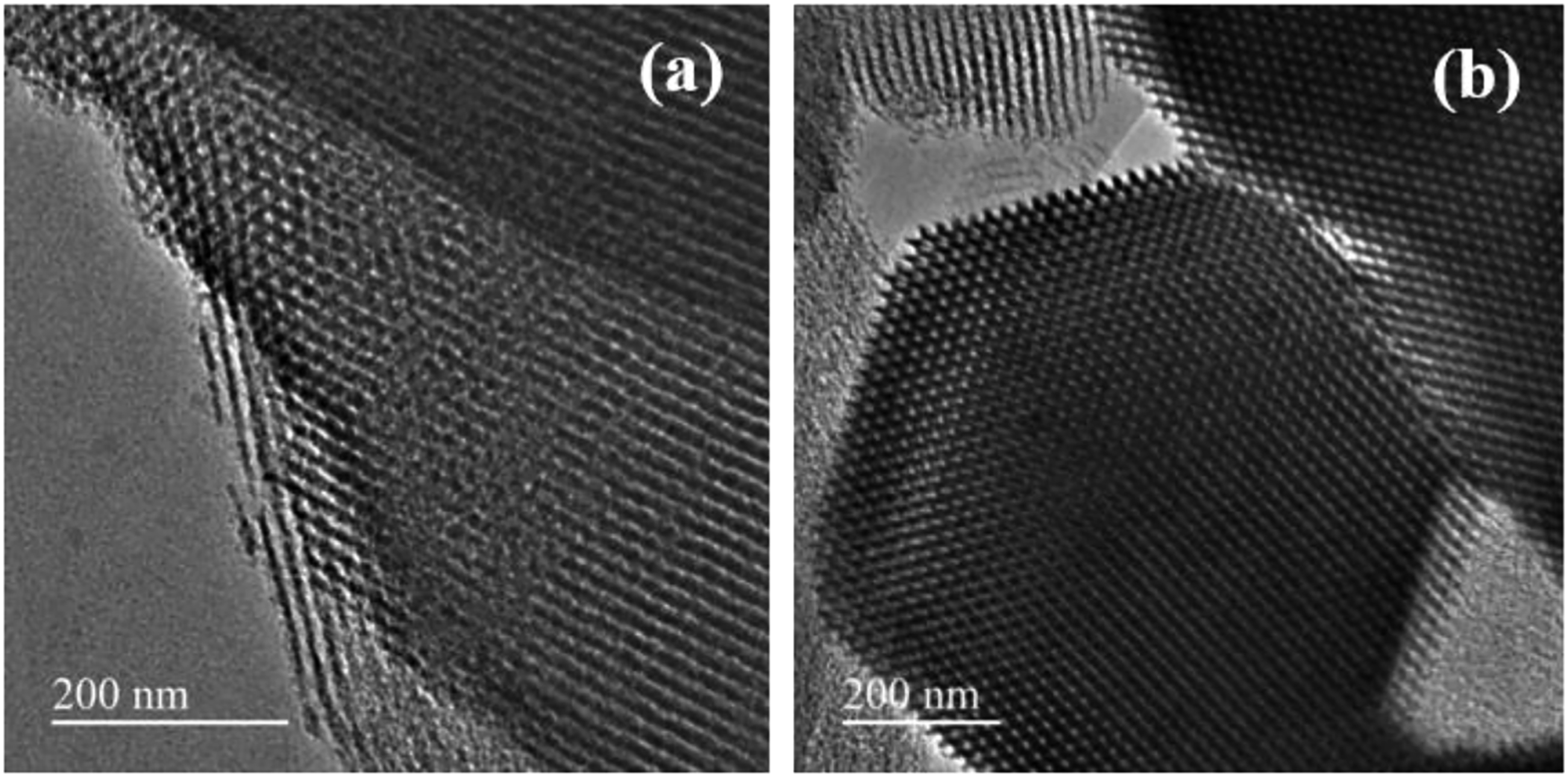
FTIR spectra of SPSU and composite membranes
The FTIR spectra of the SPSU and composite membranes are shown in Figure 7. The characteristic peaks around 1010 cm−1, 1098 cm−1, and 1145 cm−1 confirm the presence of the -SO3H group. The peaks around 1145 cm−1 represent the symmetric stretching of the sulfonate group in PSU and are also observed for sulfonated PSU. The aromatic ring vibrations were observed around 1098 cm−1, 1581 cm−1, and 1479 cm−1. Asymmetric and symmetric C-H stretching vibrations of methyl group peaks were noted around 2880 cm−1 to 2980 cm−1. The broad peak at 3403 cm−1 indicates the presence of -OH associated with sulfonic acid groups in the sulfonated polysulfone membrane.
42
The broadening of OH peaks at 3400 cm−1 suggest the presence of hydrogen bonding between polymer and filler material.
43
The main characteristic peaks were observed in the FTIR spectra of all membranes. From the figure, it was observed that all the characteristic peaks of SSBA-15 and SPSU were also observed in spectra of all composite membranes. FTIR spectra of (a) SSBA - 15 (b) SPSU (c) 1% SSBA - 15 + SPSU (d) 3% SSBA - 15 + SPSU (e) 5% SSBA - 15 + SPSU composite membranes.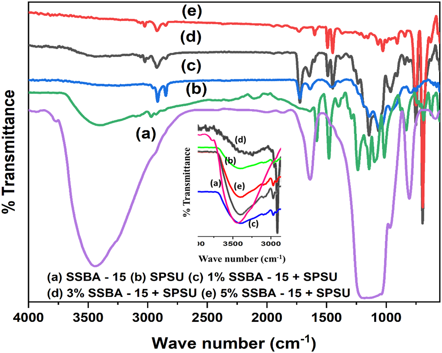
Membrane properties
Properties of the membranes.
1H NMR spectra
Sulfonation of PSU was confirmed through 1H-NMR spectra displayed in Figure 8(a) and (b). After sulfonation, the appearance of a new signal at 7.72 ppm, is assigned to the proton (2″) which is due to the newly formed pendant sulfonic acid. It is clear that the intensity (integral area) ratio of 2″ proton signal to that of other aromatic protons is closely linked to the degree of sulfonation (DS) of PSU. The Degree of sulfonation increases with an increase in the ratio.
44
The degree of sulfonation was found to be 55%. 1H-NMR spectra of (a) PSU and (b) SPSU.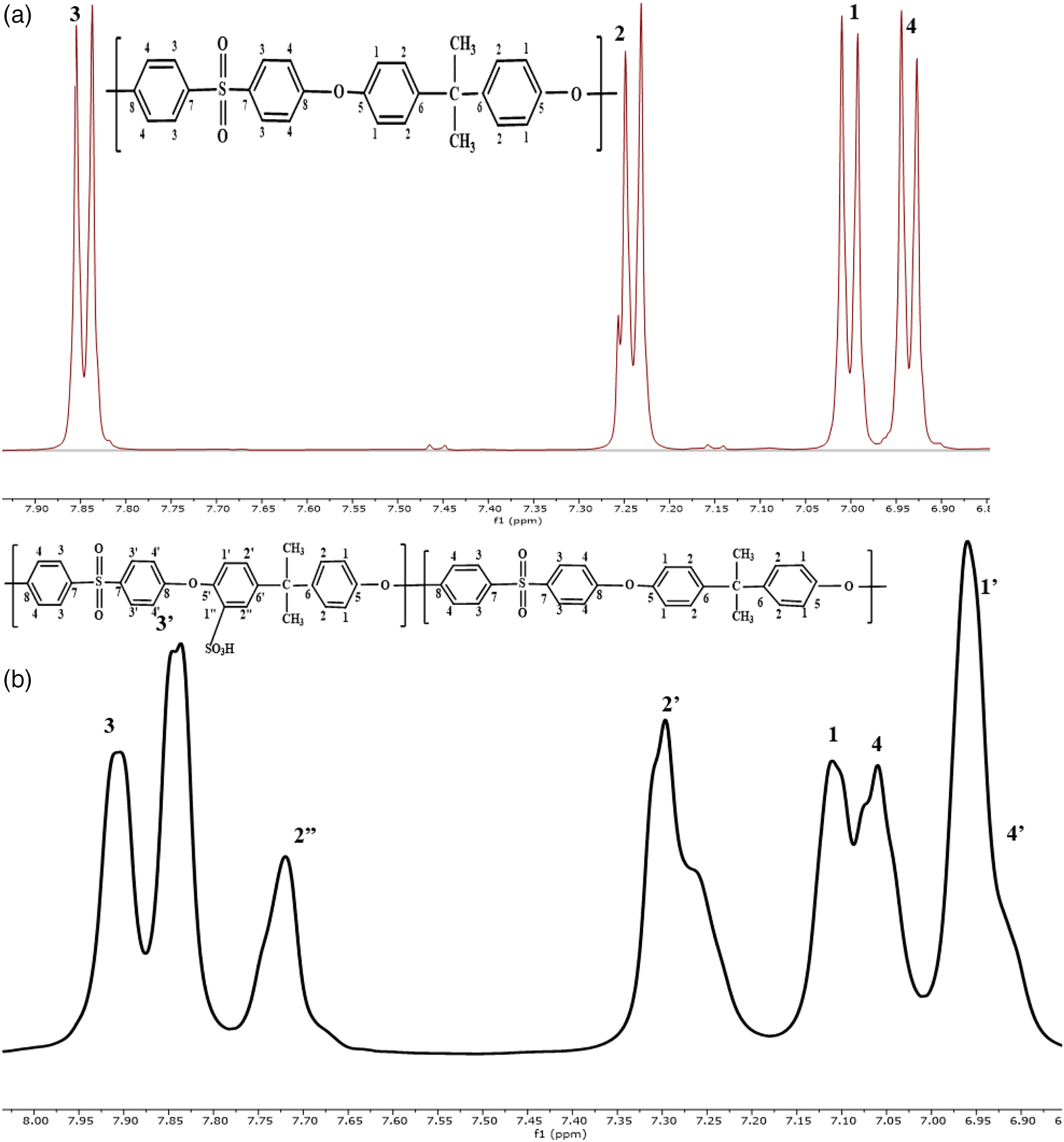
The XRD patterns of PSU, SPSU, and their composite membranes are shown in Figure 9. From the figure, it was observed that the crystalline nature of the PSU decreased upon sulfonation. Similarly, the crystalline nature of SPSU membrane decreases with the addition of sulfonated SBA -15. Among all the composite membranes prepared, 3% SSBA-15 showed the most amorphous nature while 5% SSBA-15 showed the least amorphous nature (high crystalline nature) compared to other composite membranes. The uniform distribution of the filler material (SSBA-15) in the polymer matrix and its presence between the polymer chains increases the freedom of rotation in the polymer chains, and hence the amorphous nature predominates in the composite membranes. However, 5% SSBA-15 composite membranes showed crystalline nature compared to other composite membranes which is attributed to the agglomeration of the filler material in the polymer matrix as observed from SEM images (Figure 10). With the increase in amorphous nature, the membrane forming capacity of the polymer is also increased due to increased polymer chain flexibility.
43
X-ray diffraction patterns for (a) PSU, (b) SPSU, (c) 1% SSBA-15 + SPSU, (d) 3% SSBA-15 + SPSU and (e) 5% SSBA -15 + SPSU composite membranes. SEM images of (a) SPSU, (b) 1% SSBA-15 + SPSU, (c) 3% SSBA-15 + SPSU, and (d) 5% SSBA - 15 + SPSU composite membranes.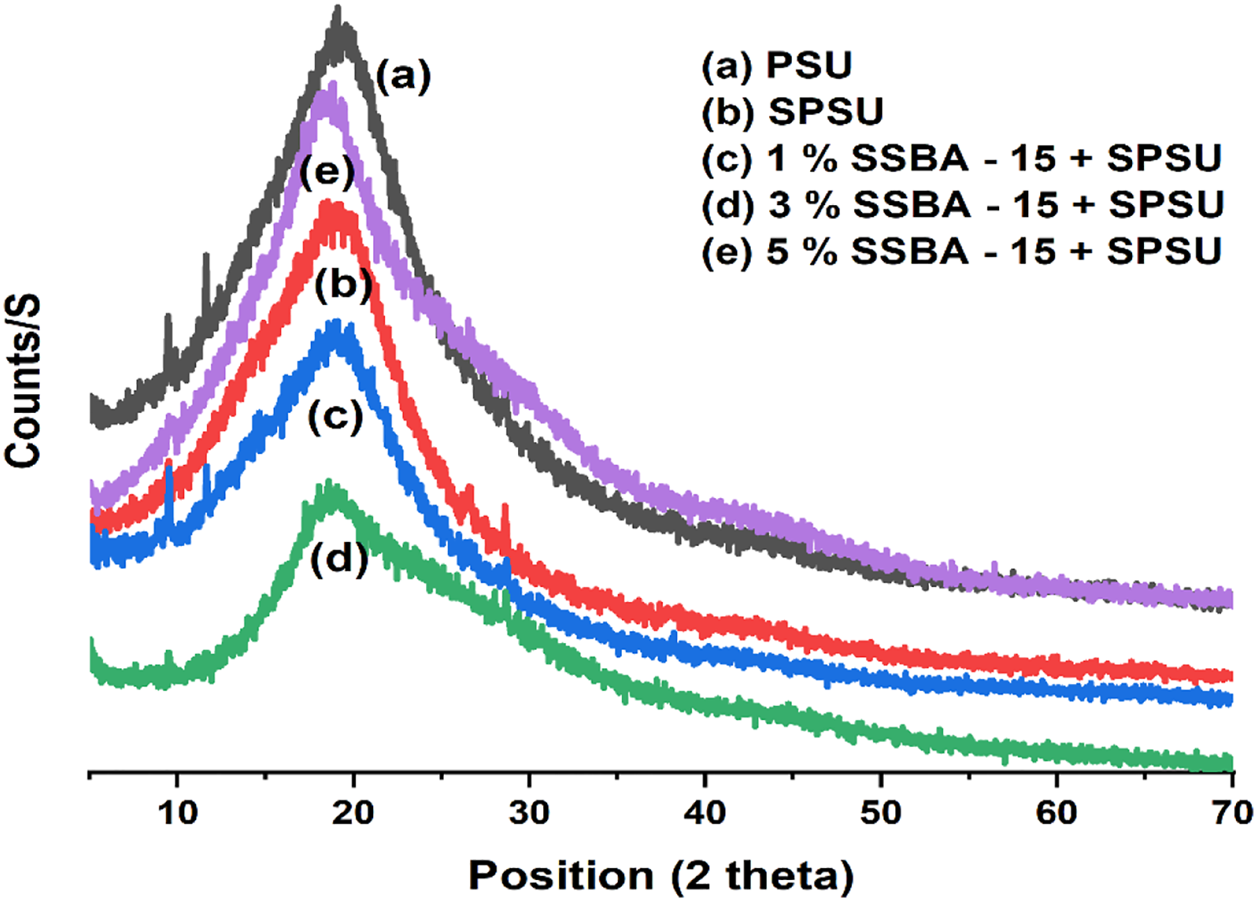
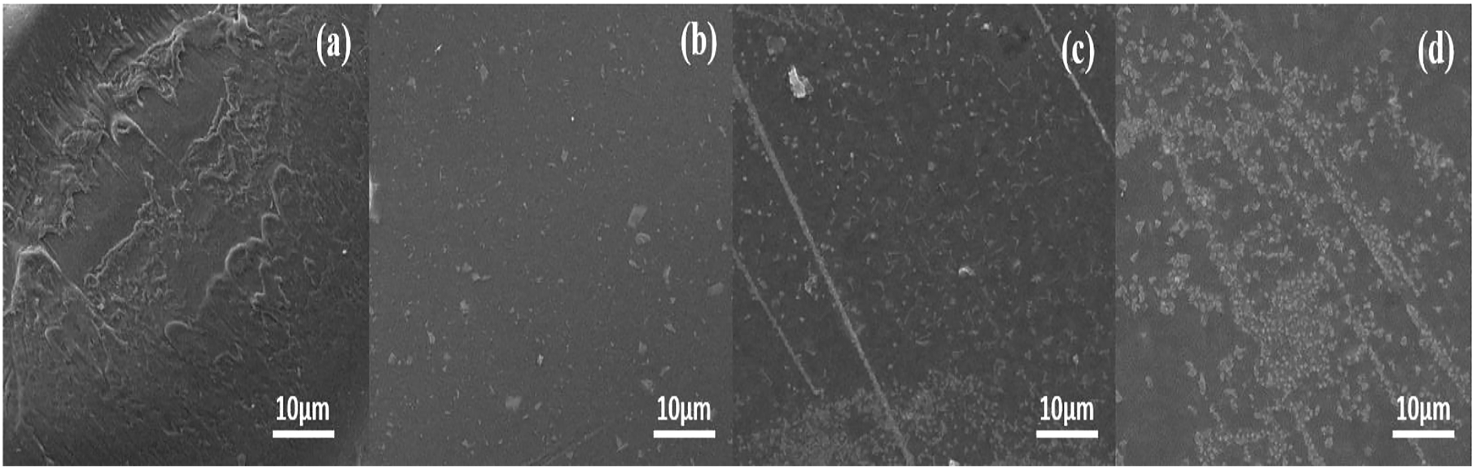
SEM
The SEM images in Figure 10 show that the surface of the SPSU and its composite membranes is homogeneous in nature, free from cracks, pores, and no phase separation was observed. However, the amount of filler content in the SPSU surface increases with an increase in the filler content. SPSU with 5% SSBA-15 showed the presence of very dense fillers on its surface with agglomeration. It was observed that silica particles play a significant role in stabilizing the chemical structure and morphology of the polymer.45,46 Phase incompatibility between the organic polymer membrane and inorganic silicate was circumvented by functionalizing the silicate surfaces. 41 The retention of textural uniformity was further confirmed with BET analysis data.
Fuel cell performance
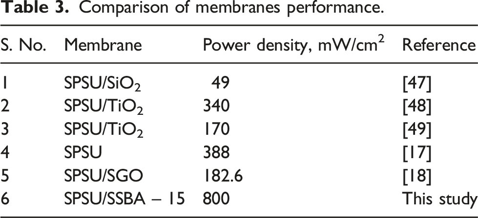
Polarization curve of 3% SSBA-15 + SPSU is given in Figure 11. The composite membrane is chosen based on its optimal membrane properties among other prepared composite membranes. The composite membrane is then used for the fabrication of MEA and tested in a single-cell fuel cell (25 cm2) for polarization study. For effective comparison of the membrane’s role in the efficiency of a fuel cell, membrane thickness, amount of platinum loading on the electrodes, and H2, and O2 flow rates were kept constant in the PEMFCs. In the fuel cell study, Nafion, SPSU, and 3% SSBA-15 + SPSU showed almost similar voltage values. However, the power density values revealed that the composite membrane performed better as compared with Nafion and SPSU. At higher temperatures, the composite membranes showed better power density values and achieved a maximum power density of 800 mW/cm2 at 80°C which were comparatively higher than those of previous reported17,18,47–49 results with polysulfone membrane with pristine and sulfonated non-porous filler materials. This was attributed to the high dense sulfonic acid groups distributed throughout the polymer matrix
43
and the porous nature of the incorporated SSBA-15 with good water retention property.21,27 The study showed that the prepared composite membrane (3% SSBA-15 + SPSU) showed better performance compared to that of Nafion 117® in terms of power density values (440 mW/cm2). (Table 3) Polarization curve for Nafion 117 (35°C), SPSU (35°C) and the prepared 3% SSBA-15 + SPSU at different temperatures (50°C, 60°C, 80°C). Comparison of membranes performance.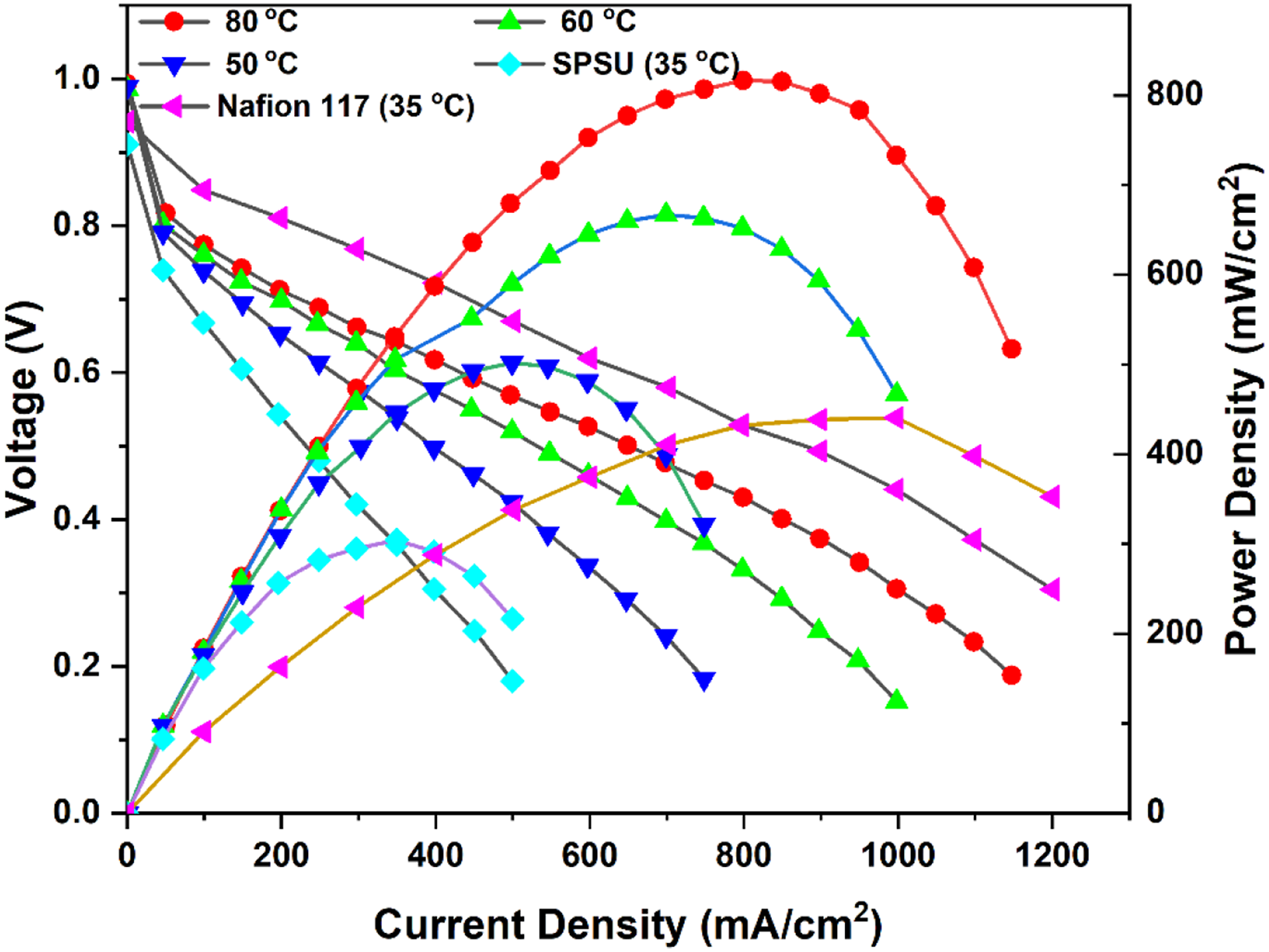
Conclusion
In the present study, sulfonated SBA-15 mesoporous incorporated SPSU composite membranes were prepared and studied in an in-house built PEMFC. Structural characterizations of SBA-15 particles before and after sulfonation from TEM images show excellent textural uniformity of hexagonal space groups. Homogeneous dispersion of SSBA-15 particles in the SPSU composite membrane was visualized from SEM analysis. The SPSU composite membrane showed higher ion exchange capacity and proton conductivity along with increased water uptake than SPSU membrane, which emphasizes the effects of the SSBA-15 particles. It showed that the porous structured SSBA-15 hold water molecules and provide additional hopping sites which acts as a medium for the transport of protons through the composite membranes. The study demonstrated that the prepared composites membranes are promising electrolyte materials for proton exchange membrane fuel cell.
Footnotes
Declaration of conflicting interests
The author(s) declared no potential conflicts of interest with respect to the research, authorship, and/or publication of this article.
Funding
The author(s) received no financial support for the research, authorship, and/or publication of this article.