
Abstract
This article addresses scheduling problems for the hybrid cellular production lines in the semiconductor industry, in which the hybrid cellular production line is defined as the production system composed of both single-functional and multi-functional cellular layouts. Detailed system configuration and material flow of a hybrid cellular production line are presented, and then, the scheduling problems in the hybrid cellular production line are separated into an inter-cell scheduling problem and intra-cell scheduling problems. A multi-agent-based scheduling method is proposed for the inter-cell scheduling problem, and a real-time heuristic scheduling method is proposed for the intra-cell scheduling problem. In the simulation experiments, various scenarios have been compared under the proposed inter-cell and intra-cell scheduling methods with the hybrid cellular production line composed of six cells.
Keywords
Introduction
As global manufacturing competitiveness is highly depending on adaptability and reconfigurability in the recent dynamic market environment, most world’s leading companies involved in the high-technology and mass customization industries, especially semiconductor and liquid crystal display (LCD), are trying to construct unique and more efficient production lines to achieve the higher market share by enhancing the global manufacturing competitiveness. This requires the advanced system configuration and control scheme of the production line, which allow the higher flexibility in production mix and the lower cycle time of products in spite of the higher throughput and the higher utilization of machines. The manufacturing system that consists of both single-functional and multi-functional cellular layouts may be able to give a clue for this problem. 1 This kind of manufacturing system is generally called as a hybrid cellular manufacturing system.
This article proposes a multi-agent-based scheduling method, considering both inter-cell and intra-cell material handling systems, for the hybrid cellular production line, that is, one of the types of wafer probe centers in the semiconductor industry. In the hybrid cellular production line, machines can be equipped functionally or multi-functionally in each cell. The functional cell implies the one in which the machines with identical operation process are equipped together, whereas the multi-functional cell implies the one in which whole or part of machine types are arranged for the smooth flow of jobs in the cell. Two tiers of the scheduler are proposed for the hybrid cellular production line: one is for the inter-cell scheduling and the other is for the intra-cell scheduling. The former is to determine how to allocate jobs to cells, and the latter is to determine how to allocate jobs to machines in a cell.
The remainder of this article is structured as follows. Section “Literature review” surveys the literature on the hybrid cellular manufacturing systems, multi-agent-based approaches in manufacturing systems, and applications of the hybrid cellular manufacturing system in semiconductor industry. In section “Description of a hybrid cellular production line,” the system configuration and the material flow are described. Section “Inter-/intra-scheduling methods” presents the scheduling methods for the inter-cell scheduling and the intra-cell scheduling. Section “Simulation experiments” provides the results of simulation experiments, and section “Conclusion” concludes this article, including discussions on the issues regarding the proposed methods.
Literature review
Regarding the hybrid cellular manufacturing system, Shambu and Suresh 1 investigate its performance by comparing with functional layout to cellular layout under several degrees of cellularization. Starting from the pure functional layout that is identical to that of the job shop, machines are gradually moved from the remainder shop to newly formed dedicated cell that processes one part family until the highest degree of cellularization is obtained. The performance metrics include setup factor, lot size, and so on. The simulation experiments reveal that the dedicated cell and the remainder shop should be effectively traded off in order to achieve the better hybrid cellular manufacturing system. Viguier and Pierreval 2 propose a two-phase method to design a hybrid cellular manufacturing system. They define stability of parts according to period of production, for example, a stable part is expected to be produced for a long time. At first, the stability analysis is performed to divide parts into the stable and the non-stable one. A genetic algorithm is used to compute parts’ route and formation of cells. Then, the stable and non-stable parts are allocated to the cells and functional layout, respectively. Suresh and Slomp 3 compare the performance of virtual cellular manufacturing with a functional layout and traditional, physical cellular layouts in a dual-resource-constrained system context. The virtual cellular manufacturing, the layout of which is identical to that of the job shop, exploits the benefits of group technology. The authors insist that the virtual cellular manufacturing offers some significant advantages, such as being more robust to turbulence in dynamic environment and enabling benefits of group technology to be realized without changing layout and significant investment. However, due to the functional layout, it retains fragmented responsibility for jobs and high transfer costs. Kesen et al. 4 present the analysis results by comparing the virtual cellular manufacturing system with the cellular layout–type and process layout–type manufacturing systems. The group-oriented scheduling rule is applied for the implementation of the virtual cellular manufacturing. From the simulation experiments, the virtual cellular manufacturing reveals the better performances in reducing mean flow time and mean tardiness. The authors also present a simplified ant colony optimization–based analytical model for the efficient estimation of the real manufacturing systems’ outputs. Satoglu and Suresh 5 propose a goal-programming model to design a hybrid cellular manufacturing system. They analyze demand volume and volatility of products with Pareto. And then, machines are assigned to manufacturing cells and a residual functional layout considering over-assignment of parts to the cells, machine purchasing cost, and loss-minimization of functional synergies. Finally, they allocate labors by considering worker capabilities and capacities. Their method is applied and evaluated on a small-sized real factory data which consist of 32 part types, 8 machine types, 2 cells, and 1 functional layout. Süer et al. 6 propose a new layered cellular manufacturing system consisted of dedicated, shared, and remainder cells to cope with the probabilistic demand environment. The dedicated cell is for only one part family, the shared cell usually processes two part families, and the remainder cell is for more than two part families. They present a hierarchical methodology to design the layered cellular manufacturing system and a heuristic procedure to determine the cell types. The performance of the proposed layered cellular manufacturing system is compared with the classical cellular manufacturing system. Satoglu et al. 7 propose a sequential approach composed of a mathematical model and heuristics for designing hybrid cellular manufacturing systems to facilitate one-piece flow. The one-piece flow is a design rule to reduce lead times in cellular manufacturing systems. The mathematical model generates the machine-part matrix while minimizing the total number of inter-cell transfers, and the axiomatic design principle–based heuristics design the flow line and estimate backflow within the cells. Renna and Ambrico 8 investigate the performance of classical cellular manufacturing systems, comparing them with fractal cells and cellular manufacturing systems with remainder cells in dynamic contingencies such as machine breakdowns, product mix changes, demand fluctuations, and processing time variability. The performance metrics include throughput, throughput times of the parts, work in process (WIP), manufacturing utilization, and due date performance. The simulation results reveal that the classical cellular manufacturing system performs better in static condition, whereas the cellular manufacturing system with remainder cells shows the better performance and has high stability under dynamic conditions. In addition, they also propose three control policies for the cellular manufacturing systems with remainder cells. Ariafar et al. 9 propose a mathematical model for facility layout design problem in a hybrid cellular manufacturing system to minimize both inter-cell and intra-cell material handling costs. A variant of a simulated annealing algorithm is developed to solve the mathematical model. The proposed algorithm is compared with benchmarked algorithm from the literature. Torabi and Amiri 10 present a two-phase approach for the design of the hybrid cellular manufacturing system. Products are classified into stable and special groups by using a newly proposed adaptive fuzzy ranking method. And then, based on an interactive possibility programming model, the stable and special products are assigned to usual cells and functional cells, respectively.
Regarding the multi-agent-based approaches in manufacturing systems, Shen and Norrie 11 and Shen et al. 12 provide reviews of the literature until 2005. Rao et al. 13 propose multi-agent-based control architecture for an agile manufacturing system. The control architecture is presented by introducing the concept of reconfigurable manufacturing cell (RMC) in order to provide the agile manufacturing system with an optimal, dynamic, and flexible mechanism. For the control architecture, five kinds of agents are defined: order management agent (OMA), task planning and RMC forming agent (TPA), resource management agent (RMA), RMC agent (CA), and machine or resource agent (MA). For the order planning and RMC forming, they present a two-step approach with a linear integer programming model and a multi-agent-system-based dynamic process model, whereas for the scheduling within RMC, they present a scheduling model based on the bidding mechanism and the rescheduling mechanism. Wong et al. 14 propose an agent-based negotiation approach to integrate process planning and scheduling in the job shop, or similar kind of flexible manufacturing environment, for the production of N parts with M machines. The proposed agent-based system consists of part agents and machine agents. The process plan for process routing and task allocation is established through negotiation protocol between the part and machine agents. Kumar et al. 15 present a hybrid negotiation mechanism for multi-agent manufacturing systems to enhance the efficiency of the system and to allocate resources to jobs. The proposed multi-agent system is composed of four types of agents: machine agents, clone agents, part agents, and mediator agents. The machine agents control the scheduling and execution of a task. The clone agents, the replicas of machine agents, maximize the utilization rate of machines in consideration of dynamic variation in the task priorities. The part agents guide the production of parts and generate feasible plans to complete the processing before the due date or to minimize tardiness. Finally, the mediator agents, acting as virtual part agents, select the best bid received from clone agents and inform the selection to the corresponding clone agents. Wang et al. 16 present a distributed shop floor scheduling framework at the shop floor level. The shop floor consists of a collection of multiple workcells, and each workcell is modeled as a flexible manufacturing system. A dynamic distributed scheduling at shop floor level is achieved by a group of schedulers through cooperation. The agent-based scheduling architecture is proposed for the workcell level. The multi-agent system consists of resource agents, a real-time controller agent, a directory facilitator, and a scheduler agent. The resource agents, representing manufacturing resources in the workcell, receive job assignments from the real-time controller agent and report the working status of their resources to the real-time controller agent. The directory facilitator provides the registration service for other agents. The real-time controller agent, representing the overall control of workcell, receives schedules from the workcell scheduler and distributes them to resources in the workcell. Finally, the scheduler works with the real-time controller within the workcell and also works with other schedulers at shop floor level. Yoon and Shen 17 propose a multi-agent-based scheduling system for semiconductor wafer fabrication facilities with hard interoperation temporal constraints. The proposed multi-agent architecture consists of scheduling agent, workcell agents, machine agents, and part agents. Based on dynamic planning-based approach, the scheduling agent generates quasi-optimal schedules through a bidding mechanism with the workcell agents. They use a concept of temporal constraint sets to obtain feasible schedules in polynomial steps. Anosike and Zhang 18 propose an agent-based integrated decision platform for the manufacturing system dynamically integrated in response to changes in the system or in the business environment. The integrated decision platform conducts optimal planning, controls decisions within the structural constraints of an existing system, and is able to identify reconfiguration options by gradually relaxing the structural constraints. Chen and Chen 19 have applied a multi-agent technology to construct a multi-section flexible manufacturing system model. The target system is a flexible transfer line for producing motorcycle cylinders. It consists of nine computer numerical control (CNC) machines, four buffers, and three rail-guided vehicles to transfer parts between the buffers and the manufacturing zones. They present a multi-agent-based flexible manufacturing system cell controller based on Java Agent Development (JADE) framework for multi-agent to combine with dispatching rules. Adam et al. 20 present a role-based manufacturing control method in a holonic multi-agent system. First, they provide an open control framework, in which the control is achieved using holonic agent in the holonic multi-agent system. After then, they propose the theoretical research on the role to provide an adaptive control system. A JADE-based simulation and real implementation results are presented to validate their approach. Nejad et al. 21 present a multi-agent architecture for process planning and scheduling for a flexible manufacturing system. The proposed multi-agent architecture is developed using the PROSA 22 and the ADAptive holonic Control aRchitecture (ADACOR). 23 They also present a negotiation protocol among agents to solve complex problems in the integrated process planning and scheduling in consideration of both the dynamic status and the disturbances of the manufacturing system. Renna 24 presents a multi-agent architecture for the real-time scheduling of cellular manufacturing systems in dynamic environment. The real-time scheduling method is based on the auction approach between the agents by evaluating the internal index, that is, failure time and machine efficiency, and external index, that is, workload of the machines. Wang et al. 25 present a dynamic scheduling method considering flexible routes and inter-cell moves in cellular manufacturing systems. A pheromone-based approach using multi-agent framework is adopted for the scheduling problem. A cellular manufacturing system consists of a number of manufacturing cells, and each cell contains a number of machines.
Some real applications of the hybrid cellular manufacturing systems can be found in the special production lines of the semiconductor industry, especially, the production lines for wafer probing or wafer test. Up to now, in the semiconductor industry, while most of scheduling research studies have been focused on the semiconductor fabrication facilities, commonly called as fabs, the wafer probe centers have been received relatively less attention. Furthermore, although there are some standard layout guidelines for the semiconductor fabrication facilities, there exist various types of production lines for the wafer probe centers. The hybrid cellular production line is one of them. There have been some research studies on the wafer probe center scheduling problem, after Ovacik and Uzsoy’s study. 26 Most of them consider the wafer probe center as a flexible flow shop as shown in Figure 1. The flexible flow shop is the extended flow shop composed of several stages with identical and/or non-identical parallel machines. 27 Bang and Kim 28 propose a heuristic scheduling algorithm for the wafer probe center that is modeled as a flexible flow shop with identical parallel machines. The objective of the algorithm is to minimize the total tardiness of orders considering the sequence-dependent setup time for different wafer lots. It determines the schedule of wafer lots at the bottleneck stage first and then computes the schedules for the other stages based on the first schedule. They also present a rolling horizon method on a dynamic situation and show that their method is better than the other existing heuristic methods through computational experiments. Chen et al. 29 propose a real-time dispatching algorithm for the wafer probe centers. They consider non-identical parallel machines and re-entrance of wafer lots for the wafer probe centers. The dispatching algorithm is driven by events such as urgent lot and idle tester, and it is a two-phase approach based on lot ranking and lot assignment. Through the simulations, they show that it is adequate for the fast-changing production lines. Lee et al. 30 propose a daily planning and scheduling system for the wafer probe centers. It plans a daily schedule to minimize the setup change-over of machines and allocates wafer lots to machines to follow the scheduled target plan based on the rolling horizon method. Although the layout of the wafer probe centers is not explained in their report, as considering the number of wafer types and the amount of daily manufacturing, we guess that it is similar to the hybrid cellular manufacturing system.
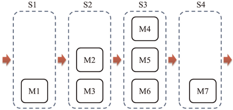
An example of a flexible flow shop.
Although the literature reveals that the hybrid cellular manufacturing system shows better performance comparing with classical cellular manufacturing system or traditional manufacturing systems in many application practices, most of research studies up to now have been focused on efficient facility layout design of the hybrid cellular manufacturing system. The hybrid cellular manufacturing system, considered in this article, is composed of several cells, each of which consists of machines and material handling systems. In designing the cells, the system parameters and performance indices, such as balances of machine utilizations, workloads of inter-cell and intra-cell material handling systems, throughput, cycle time, WIP inventory, flexibility, and adaptability, should be considered. For the hybrid cellular manufacturing system, the design of cells is the process of trading-off against each other performance indices. For instance, higher machine utilization may be usually achieved by the single-functional cellular layout, in which each cell is equipped with same machines. The drawbacks of the single-functional cellular production lines are high workload of the inter-cell material handling systems and high WIP level, which results in the higher cycle time. On the contrary, the lower cycle time may be achieved if each cell is configured so that every part starts and finishes its route within a cell. In this case, however, the workload balance of the machines becomes an important issue. In this article, we do not consider the machine allocation problem or layout design problem for the hybrid cellular production line. Thus, it is assumed that every cell is already well configured considering workload balance of machine types. The objective of this article is to define the scheduling problem of the hybrid cellular production line in the semiconductor industry and to propose real-time scheduling methods at shop floor level.
Description of a hybrid cellular production line
System configuration
Figure 2 shows an example of the conceptual model for the hybrid cellular production line with six robotic cells. Each cell is composed of a stoker (or an input/output (I/O) interface buffer), a transfer robot, and several machines. An automated guided vehicle (AGV) can be used instead of the transfer robot. There are two kinds of automated material handling systems (AMHSs): one is for the inter-cell material handling and the other is for the intra-cell material handling. Generally, the inter-cell material handling system transfers carriers (or lots), each of which contains several devices (or parts) to reduce the utilities of the vehicles of the inter-cell material handling. Although the carrier-based transportation is also applicable for the intra-cell material handling system, carrying individual device is preferable so as to achieve the workload balancing among the machines and to reduce the queueing time of the devices in the input and/or output buffers on the machines. However, the device-based transportation increases the utilities of the vehicles of the intra-cell material handling systems, which may cause a significant situation in which the throughput of the cell depends on the capabilities of the vehicles of the intra-cell material handling system. To cope with this problem, the vehicles of the intra-cell material handling systems generally have more than one slot to transfer several devices at a time. In this article, it is assumed that the lot-based transportation for the inter-cell material handling system and the device-based transportation for the intra-cell material handling system are used.
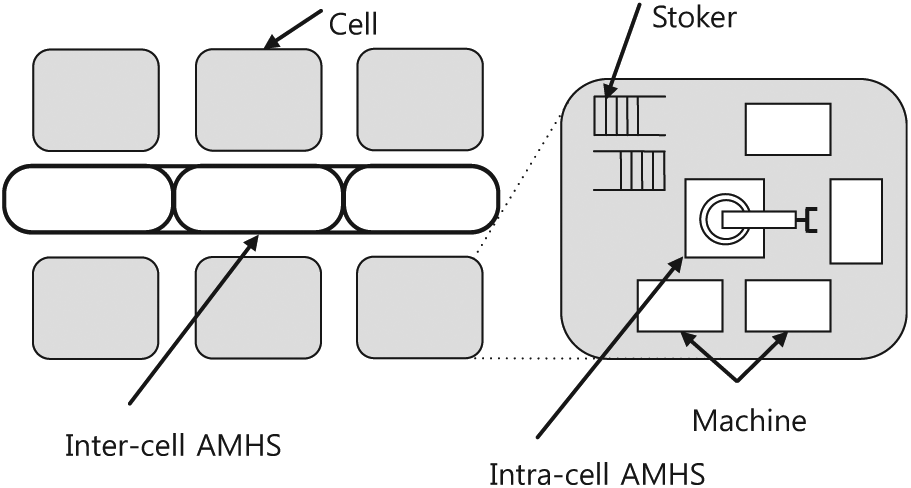
An example of a hybrid cellular production line.
Some assumptions on the system configuration are as follows:
Cell. A cell is a basic unit of the hybrid cellular production line, comprising more than one machine, a stoker, and an intra-cell AMHS.
Machine. A machine, with one operational stage, processes an operation for a device at a time. Each machine has several buffers for the devices before and after their operations. In this article, we have named them as the input and the output buffers of machines, respectively.
Stoker. A stoker is composed of shelves to store carriers, one or two crane(s) to transfer carriers within the stoker, an inter-cell I/O stage for interfacing between the stoker and the inter-cell AMHS, and an intra-cell I/O stage for interfacing between the stoker and the intra-cell AMHS.
Intra-cell AMHS. In each cell, an intra-cell AMHS delivers devices individually or collectively from stoker intra-cell I/O stage to machine, from machine to machine, and from machine to stoker intra-cell I/O stage. Generally, AGVs or transfer robots can be used for the intra-cell AMHS.
Inter-cell AMHS. An inter-cell AMHS is in charge of transportation of carriers among the cells. Generally, overhead hoist transfer (OHT) or AGV can be used for the inter-cell AMHS.
Material flow
The specific material flow in the hybrid cellular production line is defined as follows:
Inter-cell AMHS to stoker. A vehicle of the inter-cell AMHS transfers a carrier onto a stoker inter-cell I/O stage, and then, the stoker crane moves the carrier to an empty shelf in the stoker.
Stoker to machine. After transferred to the stoker intra-cell I/O stage, the carrier is waiting for the vehicle of the intra-cell AMHS so that some devices are retrieved from the carrier. After retrieving the devices from the carrier, the vehicle of the intra-cell AMHS delivers them to the input buffers of the corresponding machines, and then, the carrier is optionally moved back to the stoker shelf by the stoker crane.
Machine to machine. The vehicle of the intra-cell AMHS collects the devices completing their operations from the output buffers of the corresponding machines and then transfers and loads them to the input buffers of the machines, in which their next operations will be processed.
Machine to stoker. The devices that have completed their designated operations in the corresponding cell should be retrieved to their carriers in the stoker. Also, the devices whose next machines’ input buffers are already occupied by other devices should be temporally retrieved to their carriers in the stoker. The carriers for those devices should be located in the stoker intra-cell I/O stage before the transportation of the devices by the vehicle. If the transportation of the devices from the output buffers of the machines to the carriers in the stoker intra-cell I/O stage is completed, the carriers are moved back to the stoker shelf by the stoker crane.
Stoker to inter-cell AMHS. To transfer a carrier in the stoker shelf to the inter-cell AMHS, the stoker crane moves the carrier from the stoker shelf to the stoker inter-cell I/O stage, and then, a vehicle of the inter-cell AMHS unloads the carrier and moves it to the next cell.
Inter-/intra-scheduling methods
Inter-cell scheduling method
One of the major benefits of the hybrid cellular production line may be the lower cycle time. And this can be achieved by increasing the consecutive operation steps of carriers performed within each cell. An ideal situation would be that every carrier could complete its whole operation steps from its first operation to the final operation only in a cell. However, in many real applications, it would not be possible to reallocate machines in the cells frequently so as to maximize workload balancing of machines within and among cell(s). Therefore, for the given machine configuration in the hybrid cellular production line, if we consider the workload balancing and the utilities of the machines, some carriers should be processed in more than one cell.
For the inter-cell scheduling problem, the following decision issues should be considered:
Allocation of a newly released carrier to a cell. When a carrier is newly entered into the hybrid cellular production line, the scheduler should select a cell for the carrier and also should determine its consecutive operation steps performed in the selected cell.
Allocation of a carrier from a cell to other cell. The scheduler should select a next cell for the carrier that completes all of its designated operation steps in the current cell and should determine its consecutive operation steps in the selected next cell.
The above two decision problems are related with how to allocate a carrier to a cell for its remaining operation steps. The following two aspects should be considered in order to determine a target cell for a given carrier. First, when a target cell is to be determined for a certain carrier, the number of consecutive operation steps that can be performed in each cell should be considered. For instance, let us consider the carrier of which remaining operation steps are from op. 3 to op. 5. If both cells A and B can perform operation steps from op. 3 to op. 5 and cell C can perform only op. 3, then cells A and B should have the higher priorities than cell C. Second, the cell with the lower WIP levels related with the remaining operation steps of the carrier should have the higher priority. In the above case, if the WIP levels related with the operation steps from op. 3 to op. 5 of cell A are lower than those of cell B, then cell A should have the higher priority than cell B.
To cope with these problems, in the inter-cell scheduling, a multi-agent-based scheduling method is proposed. The proposed scheduling system consists of one inter-cell scheduling agent and several intra-cell scheduling agents. Every cell has its own intra-cell scheduling agent. The aims of the inter-cell scheduling agent are to allocate carriers to the corresponding cells and to control the vehicles of the inter-cell AMHS, and those of the intra-cell scheduling agent are to allocate devices to the corresponding machines and to control the vehicle of the intra-cell AMHS in each cell. Figure 3 illustrates the architecture of the proposed multi-agent-based scheduling system.
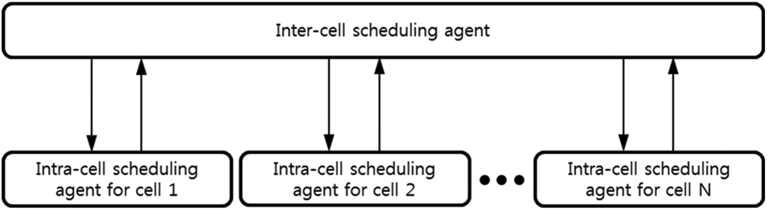
Architecture of the multi-agent-based scheduling system.
First of all, the inter-cell scheduling agent generates a list of carriers to be transferred, selects the carrier with the highest priority, and then sends the information of the selected carrier to each intra-cell scheduling agent. Considering the received carrier’s information, the current status of the machines, and the WIP levels in the cell, each intra-cell scheduling agent sends back the information regarding the carrier’s anticipated consecutive operation steps to be performed in the cell and the expected finishing time of the operation steps to the inter-cell scheduling agent. After comparing the information transmitted from each cell, the inter-cell scheduling agent determines the target cell with the highest priority for the carrier. The detailed inter-cell scheduling process is as follows:
Step 1: (inter-cell scheduling agent) make a list of the carriers to be transferred. First of all, the inter-cell scheduling agent makes a list of the carriers to be transferred from cell to cell. Each carrier is either one newly released into the hybrid cellular production line or one that, after completing its all designated operation steps in a cell, is waiting to be transferred to other cell for the next operation step(s). The information of the carrier is defined as follows:
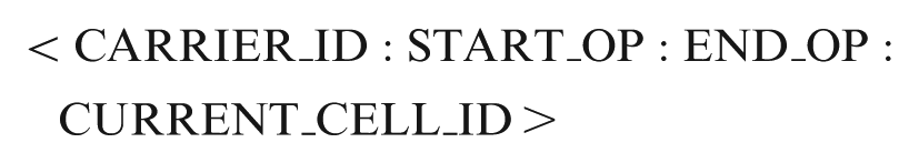
where CARRIER_ID is the identity of a carrier, and START_OP and END_OP are the identity numbers of the first and the last operations of the remaining operation steps of the carrier, respectively. For instance, if a carrier has just completed its second operation among the total five operation steps, START_OP is the third operation and END_OP is the fifth operation. CURRENT_CELL_ID is the identity of the cell, in which the carrier locates currently. For the carriers newly released into the hybrid cellular production line, CURRENT_CELL_ID is NULL.
Step 2: (inter-cell scheduling agent) select a carrier from the list of carriers. The inter-cell scheduling agent selects the carrier with the highest priority from the generated list of carriers. Generally, the carrier with the longest waiting time has the highest priority.
Step 3: (inter-cell scheduling agent) send the carrier’s information to intra-cell scheduling agents. The inter-cell scheduling agent transmits the information of the selected carrier to every intra-cell scheduling agent.
Step 4: (intra-cell scheduling agent) anticipate consecutive operation steps and expected finishing time. After receiving the carrier’s information, the intra-cell scheduling agent determines the consecutive operation steps to be processed in the cell and its expected finishing time considering the current status of the machines and the WIP levels in the cell. Then, the information on the anticipated consecutive operation steps and the expected finishing time is sent back to the inter-cell scheduling agent. The information transmitted to the inter-cell scheduling agent is defined as follows:

where FROM_OP and TO_OP are the identity numbers of the anticipated from and to operations of the consecutive operations steps that can be performed in the cell, respectively. FROM_OP will have the same number as START_OP in general case. However, if a cell has no available machine for START_OP, both FROM_OP and TO_OP will have the values of NULL. Note that TO_OP can have a different value from END_OP. The procedure to compute TO_OP is further explained below in Step 6. EXPECTED_ FINISHING_TIME is the expected finishing time for the consecutive operation steps from FROM_OP to TO_OP. EXPECTED_FINISHING_TIME can be easily computed by using the queueing times related with the operation steps.
Step 5: (inter-cell scheduling agent) determine the target cell for the carrier. After receiving information from every intra-cell scheduling agent, the inter-cell scheduling agent determines the target cell for the carrier. The decision rules of the target cell are also explained below in Step 6.
Step 6: (inter-cell scheduling agent) transmit a delivery command. The inter-cell scheduling agent transmits a command to transfer the carrier to the target cell. The delivery command is defined as follows:
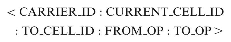
where TO_CELL_ID is the identity of the target cell.
Now, two heuristic decision rules are described as follows. This includes how to compute TO_OP in Step 4 and how to determine the target cell in Step 5.
Earliest next finishing time rule
First of all, in STEP 4, TO_OP always has the same value as FROM_OP. This implies that only the first operation of the remaining operation steps is considered in earliest next finishing time (ENFL) rule. Then, the inter-cell scheduling agent selects the target cell with the least EXPECTED_ FINISHING_TIME. After finishing its one operation step in the target cell, the carrier should find a next target cell for the remaining operation steps. Of course, the next target cell could be same as the previous target cell. Under ENFL rule, therefore, there is no machine-to-machine direct delivery of device in a cell, and carriers should find target cells for every operation step.
Most efficient in-line rule
In Step 4, TO_OP is determined by considering the machine types located in the cell and the WIP levels related with the consecutive operation steps to be processed. TO_OP is determined so that as many as consecutive operation steps can be performed in a cell within the pre-determined maximum WIP constraints. For instance, let us consider the carrier of which START_OP and END_OP are the second and fifth operations, respectively. Cell A has all machine types from the second to the fifth operation steps. The current WIP levels for the second, third, fourth, and fifth operation steps are 15, 25, 35, and 20 min, respectively. If we assume that the maximum WIP constraint is determined as 30 min, TO_OP will have the identity number of the third operation step since the WIP level of the fourth operation step is higher than 30 min. Similarly, if we assume that the maximum WIP constraint is 60 min, TO_OP will have the identity number of the fifth operation step. Then, the inter-cell scheduling agent selects the target cell with the highest TO_OP. If there are two or more cells with the highest TO_OP, the inter-cell scheduling agent selects the target cell with the least EXPECTED_FINISHING_TIME. The objective of most efficient in-line (MEIL) rule is to reduce the cycle time by increasing machine-to-machine direct deliveries of devices in every cell.
Intra-cell scheduling method
For the intra-cell scheduling, the following decision issues should be considered.
Selection and management of carriers in a stoker. The carriers in a stoker may have different operation steps, and the devices in a carrier may have different operation steps, too. The intra-cell scheduling agent should select not only a carrier to deliver the devices contained in it to the corresponding machines but also a carrier to retrieve the devices from the output buffers of machines. For both the delivery and the retrieval of devices, the corresponding carrier should be located in the stoker intra-cell I/O stage. The carriers in the stoker intra-cell I/O stages should be managed carefully, since each stoker intra-cell I/O stage has limited capacities to store carriers at a time.
Selection of devices to transfer. The intra-cell scheduling agent should select the devices to transfer from a carrier in the stoker intra-cell I/O stage or from the output buffers of machines. The maximum number of devices to transfer at a time by a vehicle is usually determined by the number of slots in the vehicle. The vehicle with more than one device does not necessarily transfer all of them to one machine. Especially, the devices from one carrier may have different operation steps. In this case, the vehicle should transfer the devices to the corresponding machines.
Selection of the target of the device. The devices in the vehicle should be transferred to the corresponding machines or to the corresponding carriers in the stoker intra-cell I/O stage. If a device completes its final operation step, it should be retrieved to the corresponding carrier. On the other hand, if a device has its remaining operation step, it can be moved to the corresponding machine for the next operation step or be retrieved to the corresponding carrier. This decision should be made by considering the queueing length of the input buffers of the corresponding machines. If there are no available spaces in the input buffers of the corresponding machines, the device should be retrieved to the carrier temporally. The intra-cell scheduling agent should also determine how to distribute the devices to the machines since there are one or more identical machines in each cell. For instance, if a vehicle has n devices with the same operation step and m identical machines for the operation step, then there are totally mˆn possibilities to distribute n devices to m identical machines. For the efficiency and simplicity in applying the scheduling procedure, the minimum transfer amount of devices at a time can be pre-determined. For instance, if the minimum transfer amount of devices at a time is 2, after the vehicle unloads four devices from a carrier, it may load two devices onto one machine and the other two devices onto another machine, considering the workload balance among the machines.
For the intra-cell scheduling method, as shown in Figure 4, we have adopted the pull approach, in which it finds available machines first and then finds devices to be allocated to the machines. The procedure of the intra-cell scheduling is as follows:
Step 1: make a list of available machines. Make a list of available machines in the cell, where the machines are sorted by their total queueing time in ascending order. The total queueing time can be easily computed by summing the standard times of every device in the input buffer of the machine. Then, go to Step 2.
Step 2: select a target machine. After selecting the first machine in the list of the available machines, register it as the target machine, TO_MACHINE, and remove the machine from the list. Then, go to Step 3. If there is no machine in the list, then go back to Step 1.
Step 3: find the devices for delivery from the output buffers of the machines and make a delivery command. Find the devices that are waiting in the output buffers of the machines after completing their operation and their next machines are compatible with TO_MACHINE. When selecting devices for delivery, the devices with the longer waiting time have the higher priorities. The number of selected devices should be less than or equal to the pre-determined minimum transfer amount of devices. If any device is found for delivery, a delivery command is made for the devices from the output buffer of the machine to TO_MACHINE, and go to Step 1; otherwise, go to Step 4.
Step 4: find the devices for delivery from the carriers on the stoker intra-cell I/O stage and make a delivery command. Find the devices that are located in the carriers on the stoker intra-cell I/O stage, and their next machines are compatible with TO_MACHINE. When selecting devices for delivery, the devices with the longer waiting time have the higher priorities. The number of selected devices should be less than or equal to the pre-determined minimum transfer amount of devices. If any device is found for delivery to TO_MACHINE, a delivery command is made for the devices from the carriers on the stoker intra-cell I/O stage to TO_MACHINE, and go to Step 1; otherwise, go to Step 5.
Step 5: find the devices for delivery from the carrier in the stoker shelf and make a delivery command. Find the devices that are located in the carrier in the stoker shelf, and their next machines are compatible with TO_MACHINE. When selecting devices for delivery, the devices with the longer waiting time have the higher priorities. If any device is found, a transfer command is made for the corresponding carrier from the stoker shelf to the stoker intra-cell I/O stage, and go to Step 1; otherwise, go to Step 6.
Step 6: find the devices for retrieving to the carrier on the stoker intra-cell I/O stage. Find the devices that are waiting at the output buffers of the machines after completing their operation and whose next target is the carrier on the stoker intra-cell I/O stage. When selecting devices for retrieving to the carrier, the devices with the longer waiting time have the higher priorities. If any device is found for delivery to the carrier, a retrieving command is made for the devices from the output buffers of the machines to the carrier on the stoker intra-cell I/O stage, and go to Step 1; otherwise, go to Step 7.
Step 7: find devices for retrieving to the carrier in the stoker shelf. Step 7 is a procedure for the devices to be retrieved to the carriers in the stoker shelves. First, find the devices that are waiting at the output buffer of the machines after completing their operation and whose next target is the carrier on the stoker shelf. When selecting devices to be retrieved to the carrier, the devices with the longer waiting time have the higher priorities. If any device is found to be retrieved to the carrier, a transfer command is made for the corresponding carrier from the stoker shelf to the stoker intra-cell I/O stage. Then go to Step 1 and repeat the whole procedure.
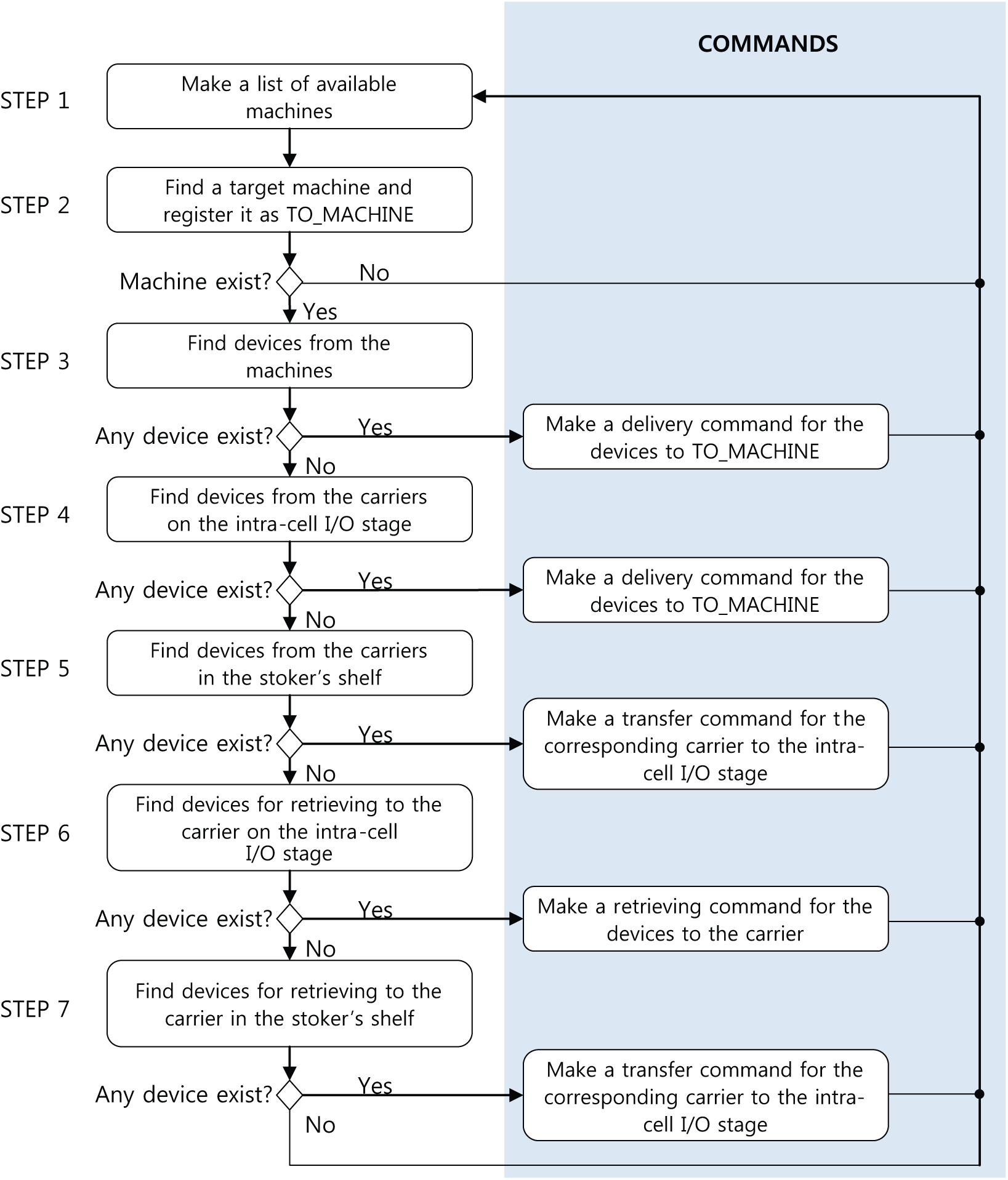
Procedure of the intra-cell scheduling.
Simulation experiments
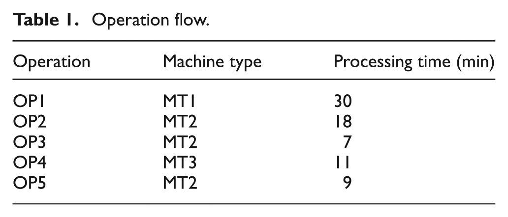
For the simulation experiment, a hybrid cellular production line composed of six cells is tested with practical data. A carrier contains 10 or 20 devices, and carriers are transferred from cell to cell. In each cell, devices are transferred among the stoker and the machines. It is assumed that OHT is used for the inter-cell transportation and AGV with six slots is used for the intra-cell transportation. The capacity of each stoker intra-cell I/O stage is assumed to be 20. Table 1 shows a machine type and a processing time for each operation step. It has totally five operation steps, and there are three machine types: MT1, MT2, and MT3. For instance, the first operation, OP1, should be processed in the machines of type MT1, and its processing time is 30 min per device. The machine configurations are shown in Table 2. The first cell, C1, consists of 14 machines of type MT1, 20 machines of MT2, and 6 machines of MT3. Thus, a device can perform its five whole operation steps in C1. Some cells such as C1, C2, C3, and C4 contain all the machine types considering workload balancing among machine types, whereas some cells such as C5 and C6 do not.
Operation flow.
Number of machines for each cell.

For the simulation experiments, since there is no algorithm compatible with the hybrid cellular production line considered in this research, we have compared various scenarios under the proposed inter-cell and intra-cell scheduling methods. The simulation model of the hybrid cellular production line and the proposed scheduling methods have been implemented by using Applied Materials’ AutoMod version 12. A total of 30 simulation runs were performed for each simulation experiment. For the simulation experiments, we have compared four scenarios as shown in Table 3. In scenario A, it is assumed that the minimum transfer amount of devices of AGV is 2, the number of devices in each carrier is 10, and ENFL is used for the inter-cell scheduling method. In scenario B, it is assumed that the minimum transfer amount of devices of AGV is 2, the number of devices in each carrier is 10, and MEIL is used for the inter-cell scheduling method. In scenario C, it is assumed that the minimum transfer amount of devices of AGV is 5, the number of devices in each carrier is 10, and MEIL is used for the inter-cell scheduling method. In scenario D, it is assumed that the minimum transfer amount of devices of AGV is 2, the number of devices in each carrier is 20, and MEIL is used for the inter-cell scheduling method.
Simulation scenarios.
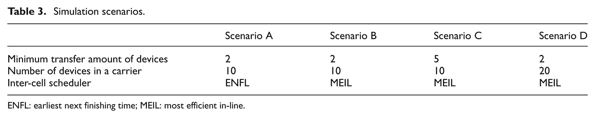
ENFL: earliest next finishing time; MEIL: most efficient in-line.
Figure 5 compares the cycle times in days under scenarios A–D. First of all, under MEIL rule (scenarios B, C, and D), it reveals that scenario B shows the best performance. This implies that, as can be easily anticipated, the smaller minimum transfer amount of devices and the smaller number of devices in each carrier affect the decrease in the cycle time. Regarding ENFL and MEIL rules (scenarios A and B), the simulation result shows that the cycle time is reduced by 61% when MEIL rule is applied. ENFL rule is much simpler for the application than MEIL rule since the former considers only the WIP level of the next first operation step when selecting the target cell. However, every device that finishes its operation in the corresponding machine should be retrieved to its carrier in the stoker since there is no machine-to-machine direct delivery in a cell, and therefore, the cycle time is increased. On the other hand, MEIL rule increases the machine-to-machine direct deliveries of devices in every cell and, therefore, is more effective in decreasing the cycle time.
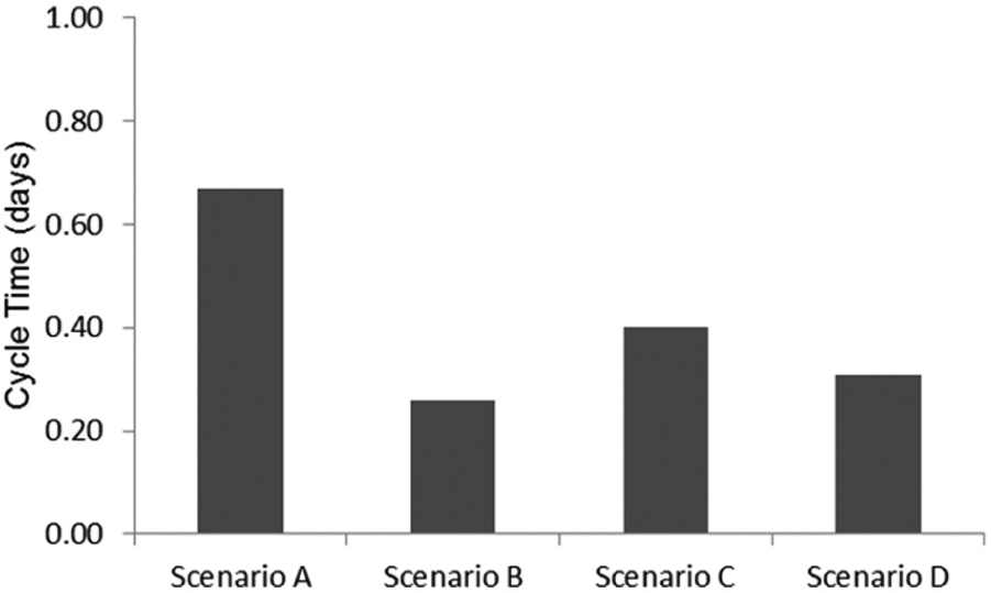
Cycle times under scenarios A–D.
Figure 6 shows the utilities of intra-cell vehicles and stoker cranes in percentages under scenarios A–D. Under MEIL rule (scenarios B, C, and D), the smaller minimum transfer amount of devices results in the higher utilities of the intra-cell vehicles. Regarding ENFL and MEIL rules (scenarios A and B), the utilities of both the intra-cell vehicles and the stoker cranes are much higher when ENFL is applied. This is because the intra-cell vehicles and the stoker cranes should deliver devices and carriers more frequently under ENFL since ENFL has no machine-to-machine direct delivery in a cell. However, regarding the utilities of the intra-cell vehicles and stoker cranes, although scenario C shows the best performances, scenarios A, B, and D would also be applicable in real production line since their utilities are still below 60%.
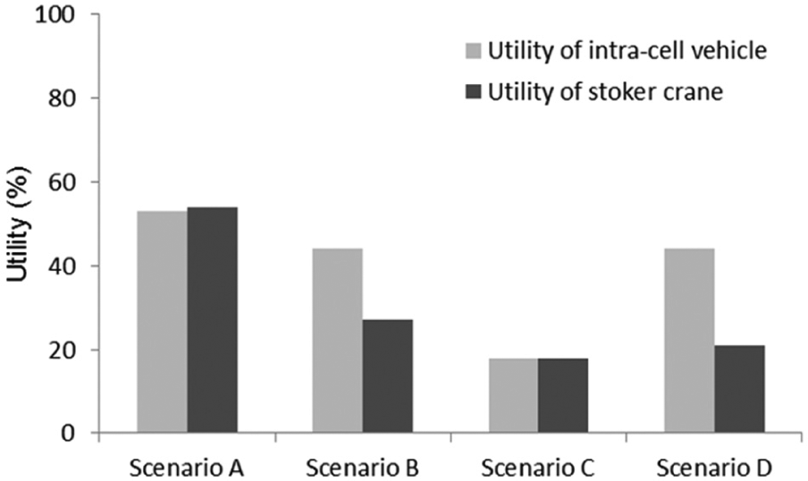
The utilities of intra-cell vehicles and stoker cranes under scenarios A–D.
Figures 7 and 8 show subsidiary information of the simulation experiments. Figure 7 compares the maximum number of carriers in the stoker intra-cell I/O stages and the maximum number of open carriers in each stoker. The number of carriers in the stoker intra-cell I/O stage is important since there are spatial limitations in the stoker intra-cell I/O stages. An open carrier implies the carrier, after starting operation in the cell, at least one device of which is not retrieved yet. Finally, Figure 8 shows the average queueing lengths in the input and output buffers of machines under scenarios A–D. The simulation results show that there are no significant differences between the scenarios.
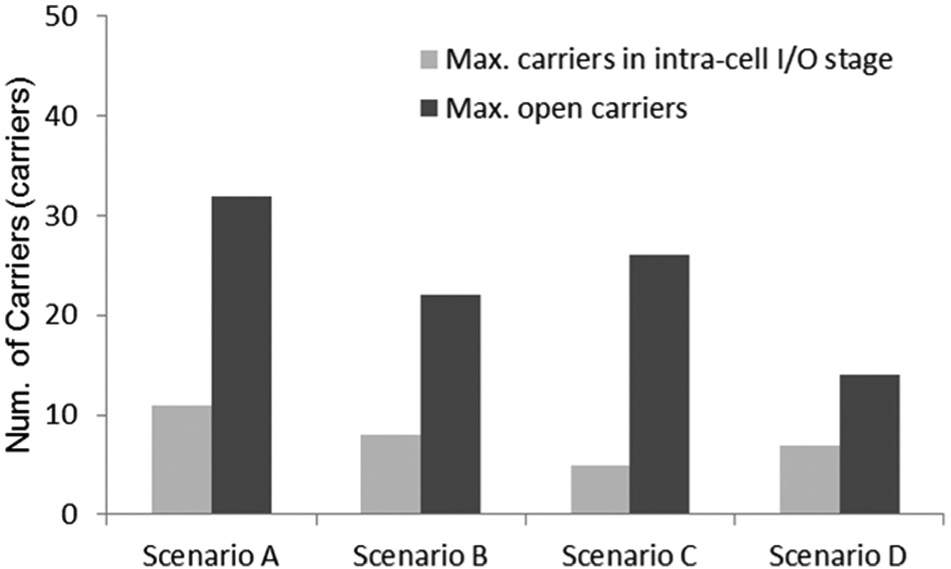
The maximum number of carriers in the stoker intra-cell I/O stage and the maximum number of open carriers in the stoker under scenarios A–D.
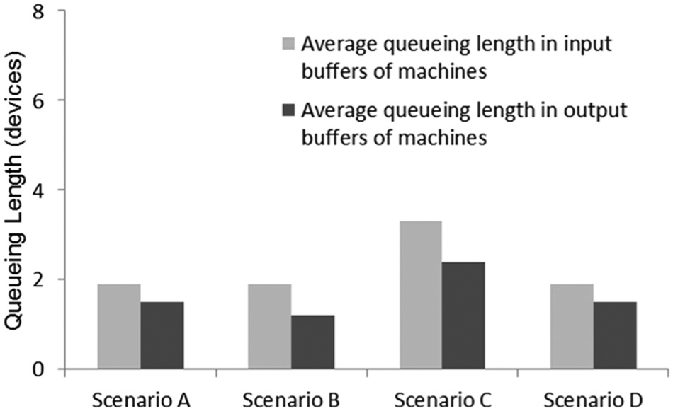
The average queueing length in input and output buffers of machines under scenarios A–D.
Conclusion
This article addresses the scheduling problems for the hybrid cellular production lines in the semiconductor industry. Some real applications of the hybrid cellular production lines can be found in the semiconductor wafer probing or wafer test centers. After defining the detailed system configuration and material flow of the hybrid cellular production line, we have separated the scheduling problems of the hybrid cellular production line into the inter-cell and intra-cell scheduling problems. A multi-agent-based scheduling method is proposed for the inter-cell scheduling problem, and a real-time heuristic scheduling method is proposed for the intra-cell scheduling problem. In the simulation experiments, since there is no algorithm compatible with the hybrid cellular production line considered in this article, we have compared four scenarios under the proposed inter-cell and intra-cell scheduling methods with the practical data of the hybrid cellular production line composed of six cells. The scenarios are determined by changing the minimum transfer amount of devices, the number of devices in a carrier, and inter-cell scheduler, that is, ENFL and MEIL rules. The limitations of this research are that it does not consider the layout optimization problem of the hybrid cellular production line and machine setup times, which will be covered in our future research.
Footnotes
Declaration of conflicting interests
The authors declare that there is no conflict of interest.
Funding
This work was supported by research grants from the Catholic University of Daegu in 2012.