
Abstract
Responding to the rise of temporary architecture motivated by fast changing cultural and societal interests, construction methods must be adapted to meet the needs of reconfigurable systems. The prototype of Snap-Interlock Module System (SIMS) proposed in this study aims to integrate the simplicity of dry stacking as a primitive construction method through a coordinated joint system in order to increase material efficiency and structural integrity. This study explores a method of stacking blocks using unique interconnecting mechanisms without bonding agents to allow for reconfigurability. The considered unit of SIMS is configured to have four legs with integrated hooks on both top and bottom, allowing each block to snap into four adjacent blocks on either end. The centerpiece is designed such that each block can individually possess geometric versatility toward organic growth of the whole system. Larger assemblies of SIMS blocks can create full-scale structures without the use of bolting, welding, or other bonding agents. Finite element analysis demonstrates that the explored interlocking motion falls into the elastic range of the considered steel and confirms that structural integrity can be secured at the building scale as well. In order to test the proof-of-concept, 1:3 scaled Polylactic Acid (PLA) blocks are 3D printed and assembled into a 2.5 m tall portal frame, leading to a full-scale structural model executed with six full-scale steel blocks. The assembly and disassembly of both prototype structures are easily executed by a single individual. Despite the limitations of the chosen fabrication methods and material choices, the study promises diverse applications in the changing urban context and contributes to the broader sustainability of our built environment via an alternative and reconfigurable construction method.
Introduction
Contemporary cities need more flexible, deployable, and reconfigurable construction methods to support the emerging culture of temporary architecture. Globalization celebrates heterogeneous desires from diverse groups, enabling flexible, functional, and transient spaces to emerge as major urban experiences. Temporary markets and stores, pop-up restaurants and hotels, short-term office pods, and eventful short-term commercial spaces are appearing and disappearing in cities around the world. Cate St Hill’s book, This is Temporary: How Transient Projects are Redefining Architecture, 1 frames temporary architecture as an opportunity to investigate novel building techniques, explore complex social and cultural issues, and communicate with neighborhoods and communities. The performance of temporary architecture is further presented to a worldwide audience through recurring events and installations such as the Serpentine Pavilions 2 and the MOMA PS1’s Young Architects Program. 3 These events encourage participation from large, well-known practices, and typically deliver temporary architecture in a more complete and formalized way. In these cases, the experience of these architectural spaces is shared through social media indefinitely, in direct contrast with the short lifespan of the programs themselves. The adaptive concepts relate to the ever-changing culture of public life in the city, further emphasizing the need for more flexible, deployable, and reconfigurable construction systems.
In order to reexamine standard building techniques regarding their application to temporary structures, stacking is chosen as a point of departure for its simplicity and its rich history in construction. As one of the oldest methods of construction, stacking is exhibited in works such as the Great Wall of China, the Hagia Sophia, the Taj Mahal, and countless others. In such cases, masonry structures are assembled by stacking bricks, stones, blocks, or tiles using bonding agents. Stacking has been one of the most common building types for load-bearing structural systems as well as non-load-bearing cladding systems throughout history. However, despite the simplicity of stacking procedure used in masonry systems, conventional stacking systems require skilled experts to control heat, water, and other environmental aspects during construction, adding a significant amount of complexity to the stacking process. In the case of more advanced digital solutions such as bricklaying robots,4,5 a significant amount of human intervention is still required to manage the bonding agent and assist throughout the construction process.
In order to circumvent the use of bonding agent, dry stack masonry systems have been used for their structural characteristics.6–9 While these systems can allow for constructions with a single masonry material, the stacking process relies on the precision of the blocks themselves to control the tolerance and stability of the overall system. Recent research has investigated non-adhesive, dry stack systems using advanced digital fabrication technology. Cyclopean Cannibalism uses a multi-axis robotic arm on large-scale discarded debris to execute complicated edge-to-edge bearing conditions. 10 Armadillo Vault 11 presents a shell structure that spans 52′ (16 m) using planar masonry units that are machined to fit precisely together without binding reinforcement, achieving the final form through the global funicular geometry of the vault itself. In the research of Karola Dierichs (Granular Architectures), units are mass produced and stacked randomly without calculated joints or binding media. The system allows a vertical aggregation of units with full reconfigurability. ETH Zurich and the MIT Self-Assembly Lab also investigated a system without bonding agents; the Rock Print. 12 Since the rock units within the prototype are unable to achieve a stable assembly, a multi-material system was created using a minimal amount of pre-formed metal wire to support and guide the formation of the rock granules. Although the form becomes stable, Rock Print relies heavily on the redundancy and excess of material to support the project’s formal requirements.
In this study, we integrate the simplicity of dry stacking with a coordination-based modular system of universal blocks in order to increase material efficiency and structural integrity while maintaining formal flexibility. The prototype of Snap-Interlock Module System (SIMS) explores a method of stacking blocks (Figure 1(a)) using a unique snap-interlocking mechanism for quick, efficient, and reversible assembly of the module (Figure 1(b)). The design details of the considered building block are illustrated in Section 2. Section 3 provides finite element analysis results showing the interlocking motion during the assembly procedure as well as the structural integrity of assembled structural module. The fabrication procedure of building blocks, prototype pavilion structure, and proof-of-concept construction of a steel structural assembly is presented in Section 4. Limitations and potential applications of this study are described in Section 5.
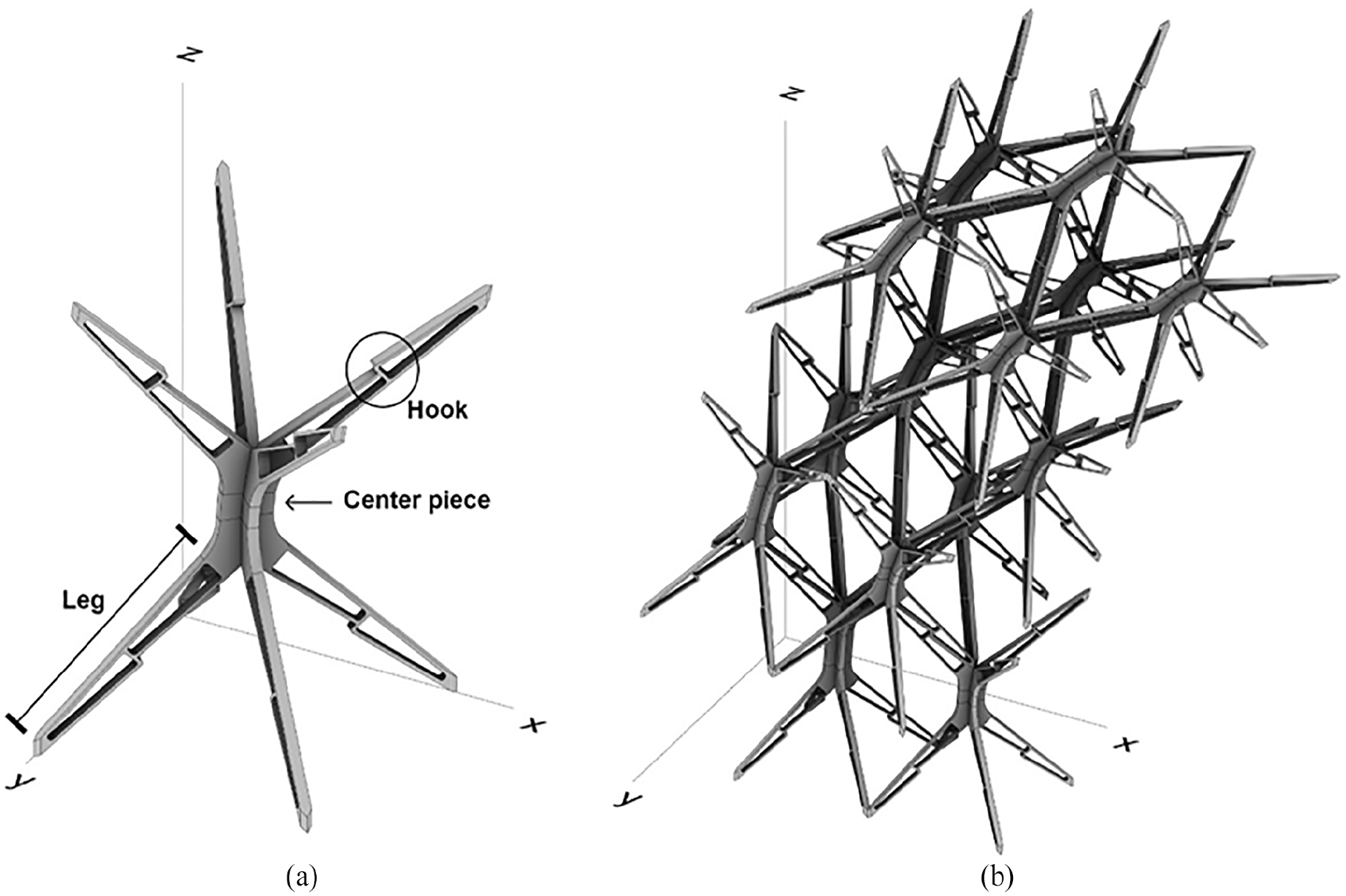
Drawing of snap-interlock module system (SIMS): (a) a unit block and (b) an assembly module constructed by SIMS blocks.
Unit block design: Performative “part” for the creative “whole”
The considered building block of SIMS consists of two main design components shown in Figure 1(a): (1) four legs on the both top and bottom and (2) the center piece of the block. The legs facilitate the snap-interlocking with adjacent building blocks through the design of hooks in the middle of the leg. The geometry controls the interlocking behavior between two connecting legs during snapping as well as the structural integrity of the connections between blocks once assembled. The geometry of the legs, which consists of the length, width, depth, and the void pattern (truss configuration), determines the structural properties of the block and also affects the ease of snapping, the esthetic of the assembly, and the surface area of connection between multiple modules. The loading capacity of the interlock connection can be varied by increasing the depth of the legs (Figure 2(a)). Furthermore, the center piece controls the overall stacking orientation and allows organic geometry of the whole structure via incremental shifts in the angle between the bottom leg assembly and the top leg assembly within each module (Figure 2(b)).
Variations of SIMS block design: (a) contact area of snapping hook and (b) angle of the center part of block.
In addition to the design of the individual building block, two stacking configurations for assembly are explored. Figure 3(a) shows a four-block-stacking configuration where connecting legs meet each other perpendicularly. On the other hand, Figure 3(b) depicts a six-block-stacking configuration in which legs meet each other in a parallel direction, creating full leg-to-leg contact. In both cases, a limited elastic movement of the hook area in the legs provides the snap-interlocking to other legs. Once the interlock is complete, the four or six blocks function as one stable module. The disassembly of the blocks can be completed by applying twisting moments to the interlocked legs. In this study, we select the second stacking configuration composed of four blocks in the middle interlocking with a single top and a single bottom block for its ability to easily expand in multiple axes with increased lateral stability.
Two different stacking patterns depending on the direction on growth pattern: (a) four-block stacking configuration and (b) six-block stacking configuration.
Finite element analysis: Structural performance of the “part” and “whole”
The structural integrity of the considered systems is studied by performing a series of finite element simulations. Envisioning full-scale habitable steel structures, we consider the mechanical properties of typical structural steel. The details of the employed material properties can be found in Table 1. Note that a linear elastic model (Young’s modulus of E = 205 GPa) together with a bi-linear plastic model (yield stress of σy0 = 400 MPa) is adopted to capture the overall material properties of the structural steel. Two different types of systems are investigated: (a) interlocking motion of a full-scale steel module composed of five steel building blocks and (b) load-resistance of a full-scale steel portal frame.
Material properties of the considered structural steel.
Full-scale steel module
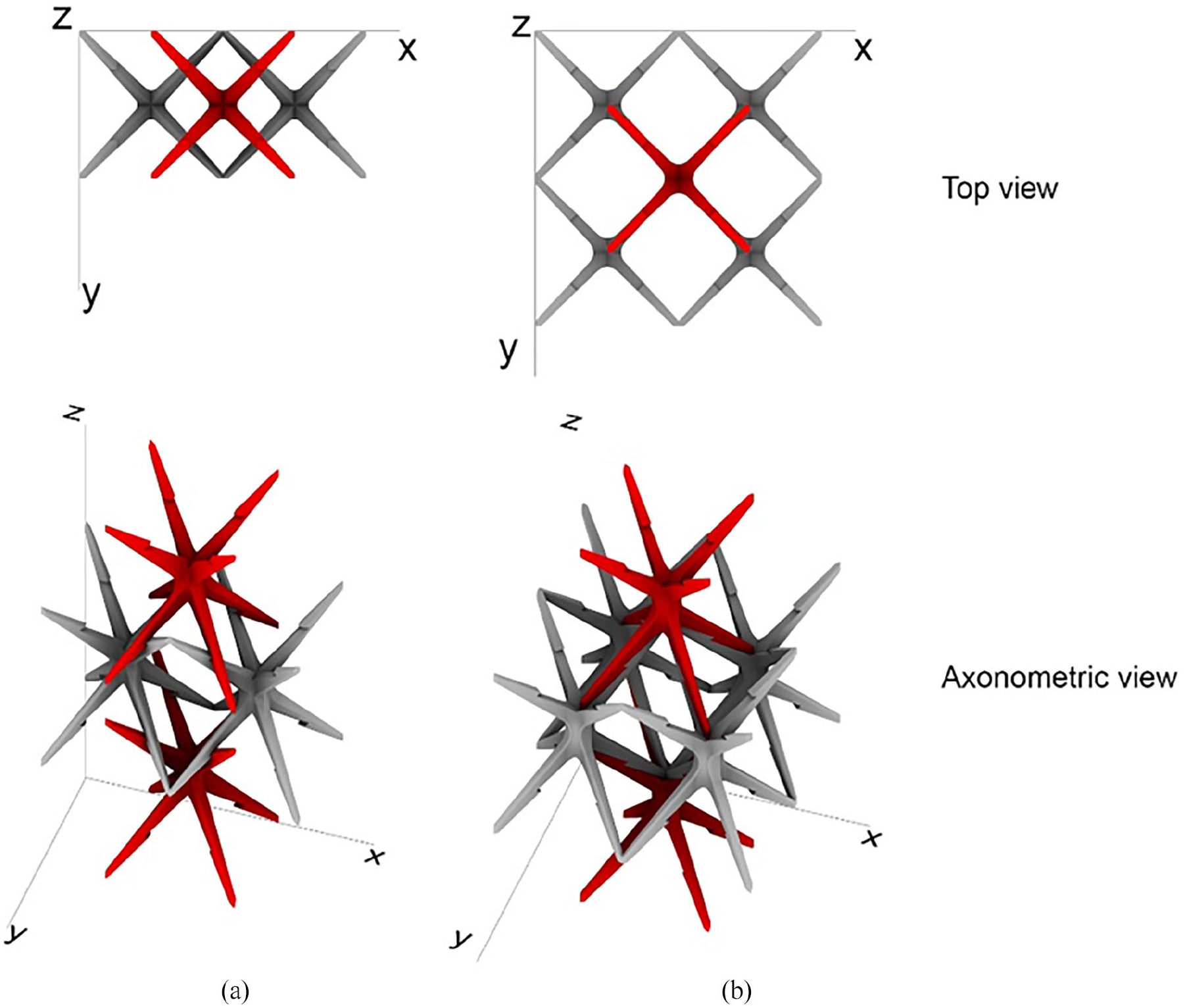
The snapping motion of the considered building blocks is investigated by simulating the assembly procedure of a full-scale steel module composed of five building blocks. The initial configuration and arrangement of the separated five building blocks is shown in Figure 4(a). Finite element analysis simulates the downward motion of the single top building block inserted into the four building blocks fixed at the bottom. Figure 4(a) to (f) illustrate the snapshot of the progressive deformed shapes during the assembly procedure. Note that fixed boundary conditions are applied at the support of four bottom blocks while the single top block moves downward with the displacement-controlled setting. The assembly procedure is completed at the stage of Figure 4(f).
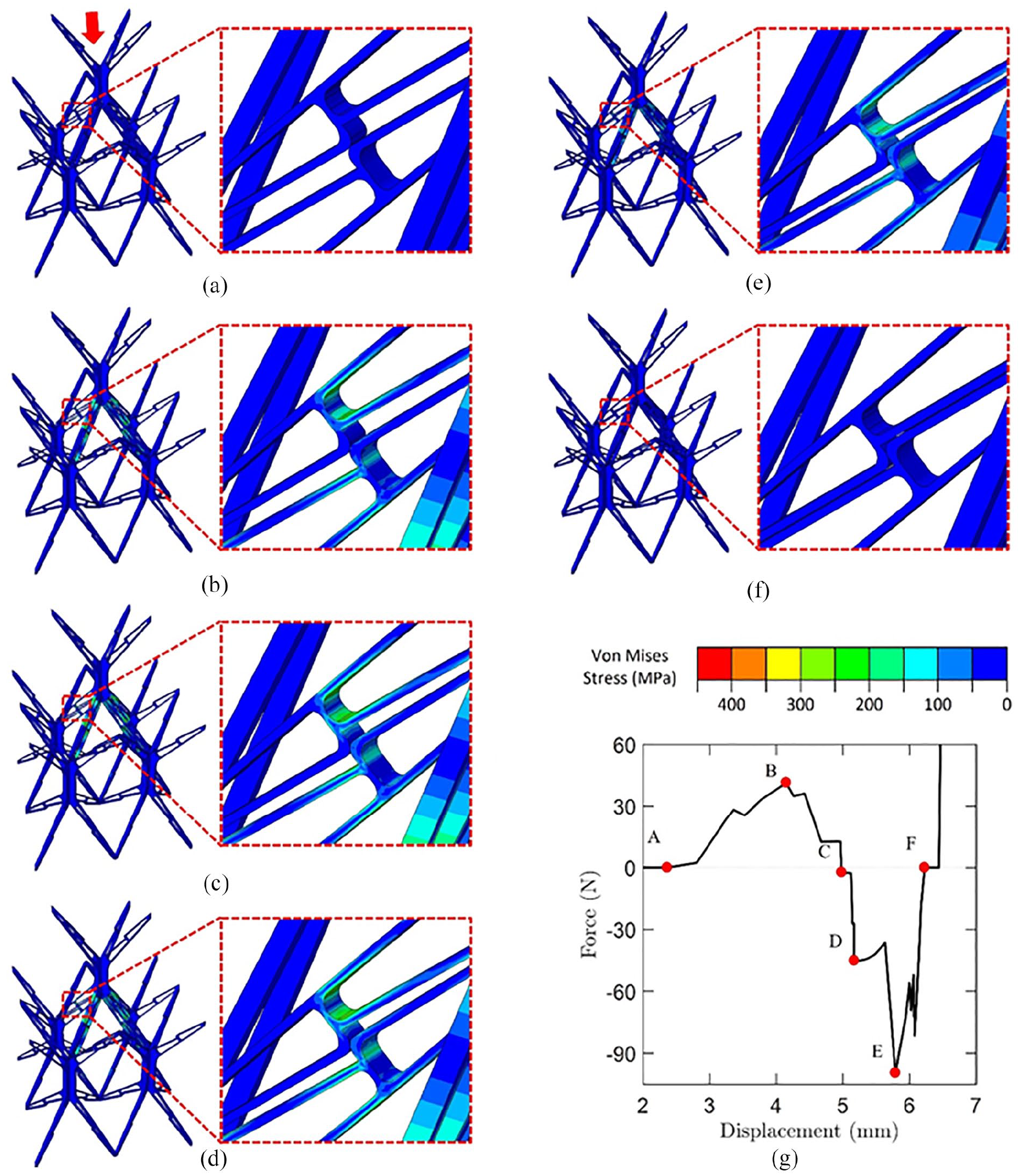
FEM simulation of the full-scale steel module: (a–f) Progressive deformed shapes of five building block assembly procedure and (g) the corresponding force-displacement curve.
The simulation reveals that the maximum stress level during the assembly procedure (<1.5 MPa) is well below the yield stress (σy = 400 MPa) of the considered steel. In addition, Figure 4(g) shows the corresponding load-displacement relation measured from the top building block. Note that each letter (i.e. a–f) in Figure 4(g) indicates the corresponding snapshot deformed shape shown in Figure 4(a) to (f), respectively. Throughout the assembly procedure of the five building blocks, we observe multiple force-drops (see Figure 4(g)), which manifest progressive snapping motions in the interlocking process. In particular, the displacement-controlled setting enables us to observe the snapping-induced lifting motion of the bottom building blocks which is shown as the negative force between the stages of Figure 4(c) to (e) in Figure 4(g). Furthermore, the load-displacement relation in Figure 4(g) also shows that the completion of the assembly task requires only the application of force less than 100 N (~10 kgf), which can be later modified by changing the specific dimensions of the building blocks (i.e. the thickness and the size of the interlocking segments). Note that the simulation assumes the constant direction of applied downward motion during the assembly procedure. However, when the building blocks are assembled in situ, maneuvering of the actual force direction will substantially reduce the required force.
Full-scale steel portal frame
Another series of finite element simulations are performed to study the integrity of a full-scale steel portal frame subjected to two different loading conditions: (1) vertical and (2) horizontal external loads. The configuration of the full-scale structure under consideration is presented in Figure 5(a), and a realistic, habitable architectural system can be constructed by assembling a series of these considered portal frames in the out-of-plane direction (i.e. the Y-axis direction in Figure 5(a)). Prior to the external loading imposed on the considered portal frame, we first applied the self-weight of the structure (~160 N in total). The fixed boundary conditions at the bottom of the structure are denoted by the orange color in Figure 5(a), and the von Mises stress distribution due to the self-weight is shown in Figure 5(b). The FE analysis shows that the maximum von Mises stress (
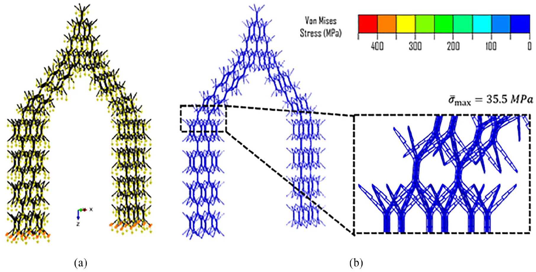
FEM simulation of the full-scale portal frame subjected to the self-weight: (a) overview of the considered structure and the applied boundary conditions denoted by orange color and (b) von Mises stress distribution due to the self-weight of the structure.
After the self-weight loading, the displacement-controlled procedure is separately adopted for each external loading condition. Figures 6 and 7 show the simulation results of the vertical and the horizontal loading cases, respectively. The overall boundary and loading conditions for the vertical load case are illustrated in Figure 6(a).
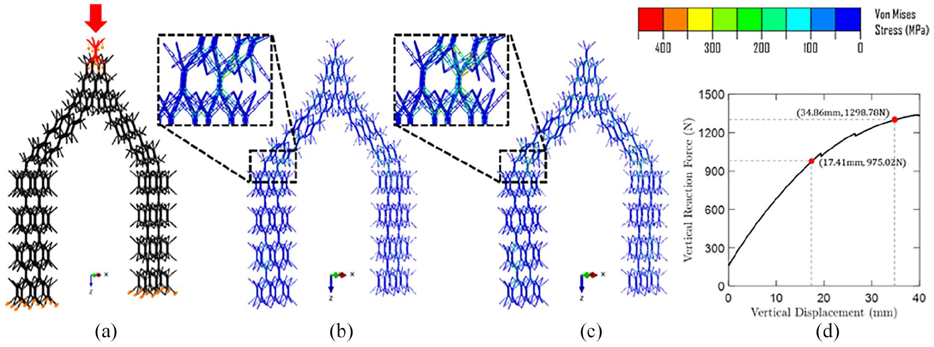
FEM simulation of the full-scale portal frame subjected to vertical external load: (a) overview of boundary and loading conditions, (b) plastic strain starts appearing at the vertical displacement of 11.6 mm, (c) plastic strain distribution at the vertical displacement of 22.9 mm, and (d) relation between vertical reaction force and vertical displacement.
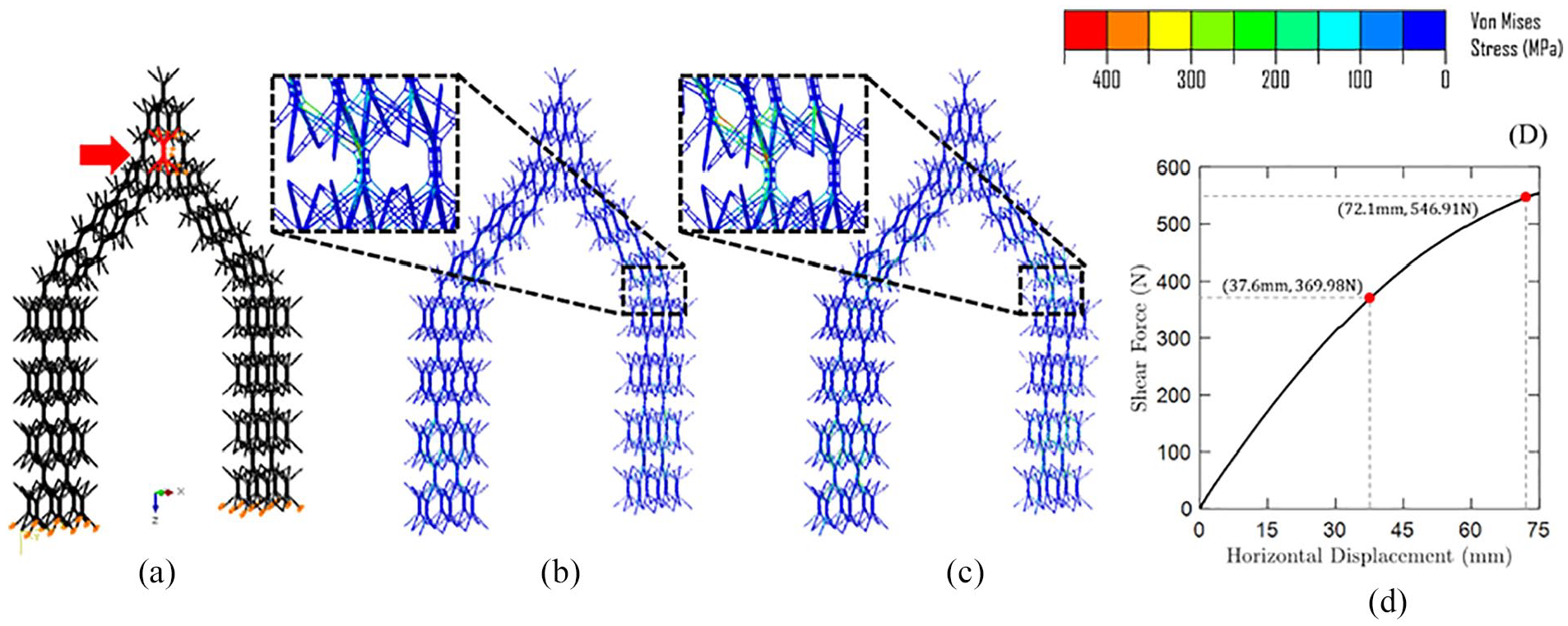
FEM simulation of the full-scale portal frame subjected to horizontal external load: (a) overview of boundary and loading conditions, (b) plastic strain starts appearing at the horizontal displacement of 23.7 mm, (c) plastic strain distribution at the horizontal displacement of 48.2 mm, and (d) relation between horizontal reaction force and horizontal displacement.
Plastic strains start appearing around the vertical displacement of 17.4 mm, but they are highly localized at the inner corner of an interlocking junction. Even after applying the vertical displacement of 34.8 mm, plastic strains are highly confined at the corners of interlocking junctions and most of the structure still remains elastic as shown in Figure 6(b) and (c). Despite the nearly linear material behavior of the considered structure, Figure 6(d) shows that the corresponding load-displacement curve is nonlinear due to geometric nonlinearity.
Unlike the vertical loading case, the horizontal load applied in the X-axis direction results in non-symmetric behavior (see Figure 7). However, the horizontal loading case also shows a nearly-elastic structural behavior as shown in the vertical loading cases. Highly localized plastic strains at the inner corner of the interlocking junctions start appearing around the horizontal displacement of 37.6 mm (Figure 7(b)), but they hardly affect the overall integrity of the structure. The stress distribution at the horizontal displacement of 72.1 mm is given in Figure 7(c), and the corresponding load-displacement curve is also presented in Figure 7(d).
The finite element simulations presented in this section verify the elastic snapping motion of the explored structures during the interlocking procedure. In addition, they demonstrate that the assembled structure can maintain structural integrity even after applying substantially large external deformation and loading.
Fabrication of snap-interlock module system
Based on the numerical structural analysis of the snap-interlocking performance, a scaled portal frame and a six block full-scale steel prototype are constructed. Due to its low cost and relatively fast production time, fused deposition modeling (FDM) 3D printing is utilized with PLA (Polylactic Acid) filament to execute the portal frame and subtractive manufacturing through waterjet cutting is used for the full-scale steel prototype to examine the steel assembly at the building scale application.
Fabrication of a scaled 3D printed PLA portal frame
We investigate building blocks at a 1:3 scale to build a 2.5 m tall proof-of-concept portal frame. The whole unit block shown in Figure 8(d) can be 3D printed without the need to separate the legs from the center piece. However, all components for the block are printed flat, then assembled to more closely simulate the steel prototype fabrication from flat plate material. A single unit block is composed of four parts for the legs and two parts for the center piece (see Figure 8(a)). Using a simple perpendicular half cross lap joint as the connection between components, leg components can be completely standardized for potential mass production. The intermediate stage of the assembly sequence for two sets of legs and the center piece is illustrated in Figure 8(b). The joint mechanism to attach the legs to the center of the module utilizes a single, beveled thread that snaps together through a 45° rotation (Figure 8(c) and (d)). A total of 434 blocks are fabricated and stacked to build the portal frame structure (Figure 9(a)). All blocks can be disassembled by applying twisting moments, packed into a single suitcase (Figure 9(b)), delivered to an exhibition site, and snap-aggregated into a small pavilion in less than 2 h.
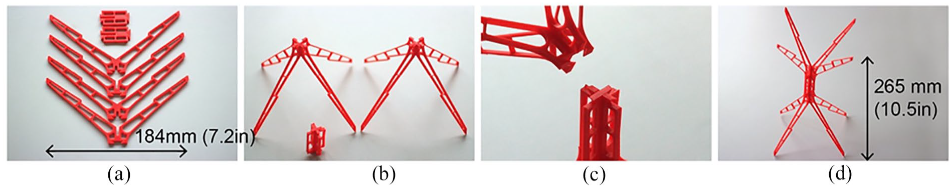
(a) Components for a unit block, (b) half cross lap joint for legs and centerpiece, (c) twist lock joint between legs and centerpiece, and (d) an assembled PLA unit block.
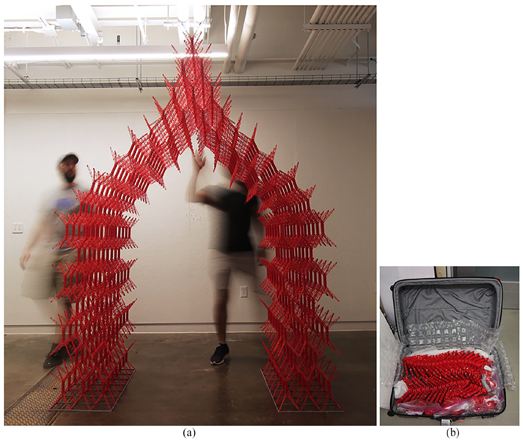
(a) 1:3 scaled SIMS prototype to test the fast assembly of arch shape pavilion and (b) the full configuration of pavilion is packed into a suitcase for transportation.
A scaled prototype structure using 3D printed building blocks and the snap interlocking procedure successfully demonstrates the applicability of modular-based stacking system to achieve organic geometry. The stacking configuration utilizes standardized leg parts for all blocks and three types of centerpieces.
Fabrication of full-scale steel six-block module
The design of the individual pieces (Figure 10(a)) is nearly identical to the design adopted within the PLA prototype structure. The major exception occurs at the connection between the center piece and the legs of the block where a redesigned arrow-shaped snap connection is used for easier disassembly. The individual pieces are cut out of a 0.375″ (9.525 mm) steel plate using a waterjet machine. Figure 10(b) shows the intermediate stage of assembly for two sets of legs and the center piece. When the leg geometry receives the center piece, the boundary profile on the leg allows the leg to push outward and snap back into place for a stable construct (Figure 10(c)). In order to demonstrate the potential for organic growth of an assembled structure, the centerpiece is designed with beveled edges for angled blocks corresponding to specific locations in the global form. While the leg component is identical for all blocks, requiring only simple 90° three-axis cutting, the fabrication process of the centerpiece adopts the use of CAMel 13 (a plugin for Rhino Grasshopper) to accurately control the required edge conditions using five-axis waterjet cutting. The assembly procedure of a unit block can be completed by a single individual without using any mechanical tools (Figure 10(d)).
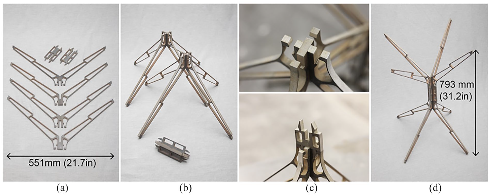
(a) 0.375″ (9.5 mm) thickness steel components for a unit block, (b) half cross lap joint for legs and centerpiece, (c) arrow shaped snap-interlocking connection, and (d) an assembled steel unit block.
There are two major connections during the assembly of the steel six-block module: leg-to-leg snapping connection (two blocks, Figure 11(a)) and end-to-end connection (four blocks + one block, Figure 11(b)). Leg-to-leg snapping can be described as a load-bearing connection that occurs in the interface between two adjacent leg surfaces (Figure 11(a)). A convex filleted corner in the hook area is designed to reduce the resistance between hooks in the process of assembly and disassembly. Once the two legs cross the threshold of the fillet, they are able to snap together with the geometry of the leg preventing the components from sliding out of place. An end-to-end connection (Figure 11(b)) refers to the connection where four legs butt against each other and interlock at the top and the underside of a single module. The completed 7′ (2.13 m) tall, six-block, snap-interlocked aggregation maintains structural integrity through the assembly process and is executed by a single individual (Figure 11(c)). The disassembly of the module can be easily completed by applying a force perpendicular to the snapping plane. All the parts of the full-scale steel prototype are disassembled within 30 min and shipped inside of a conventional suitcase for installation.
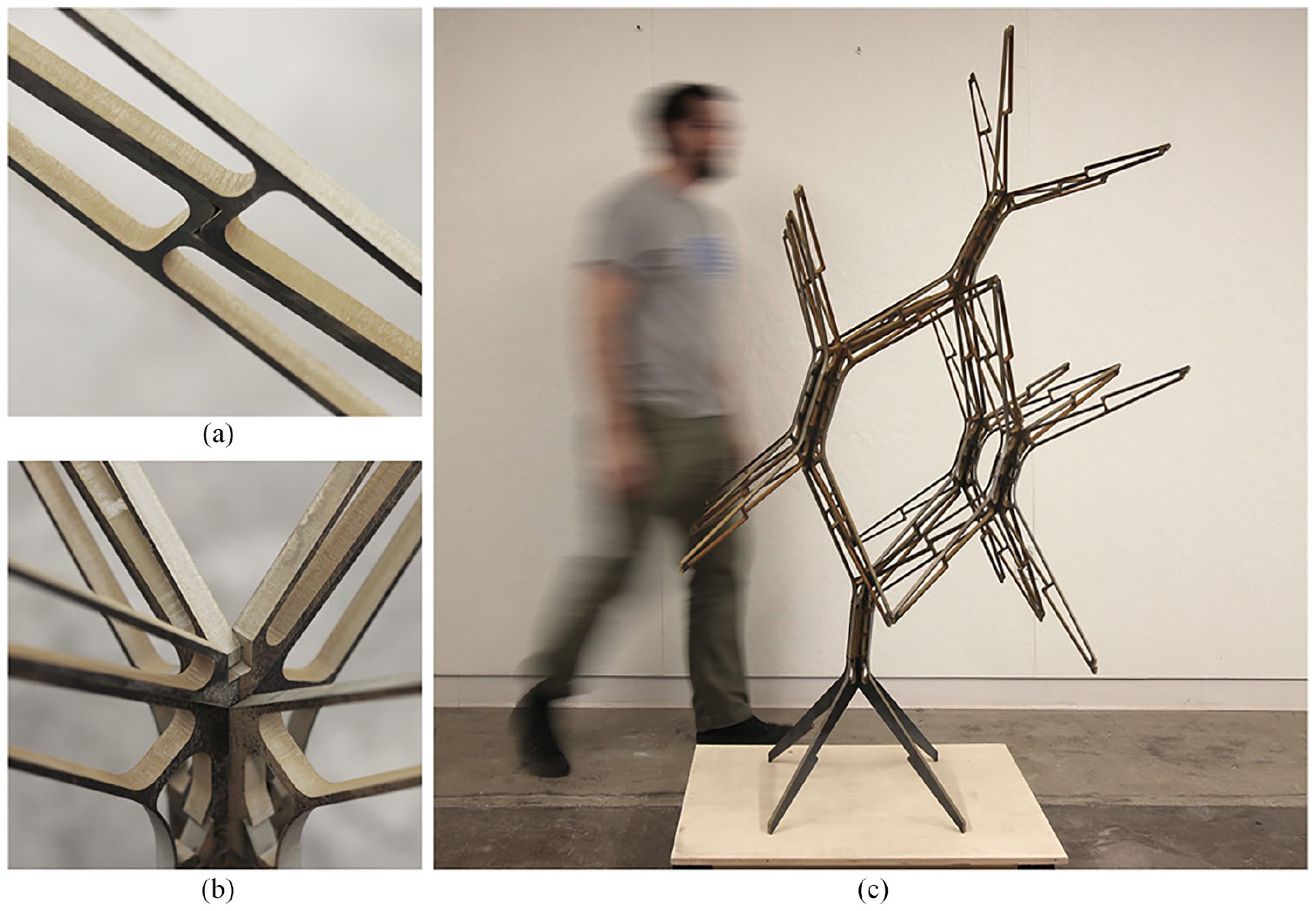
(a) Photograph showing the in plane connection within the thickness of the .375″ steel between blocks, (b) photograph illustrating a connection detail between four blocks utilizing overlapping butt connections cut in three axes, and (c) full-scale six blocks SIMS prototype.
Discussion
For the steel prototype structure, the capacity for its mass production may be limited due to the time-intensive process associated with waterjet cut steel. We can further explore alternative fabrication methods and the choice of material, which will consequently affect the geometry for snap-interlocking and structural behavior. Although the current use of CAMel and five-axis waterjet cutting has increased the viability of a variable system, additive manufacturing techniques are acknowledged for their capability to expand the geometric possibilities and customizability despite the challenges of time, cost, and post-processing. For instance, a 3D printed titanium alloy center piece, shown in Figure 12(a), confirms the potential for twisting and tilting between leg components for further geometric capability. In addition, the structural performance of the joint configuration can be further developed by considering improved disassembly procedures, potentially integrating three-axis waterjet components with custom, detachable 3D printed endcaps (Figure 12(b)). Furthermore, the use of metallic 3D printing or metal casting can improve the basic geometric characteristics of the proposed block, allowing for a wide range of design possibilities and the potential for improved interlocking and structural performance. For instance, Figure 12(c) shows various designs fabricated through the PLA 3D printing.
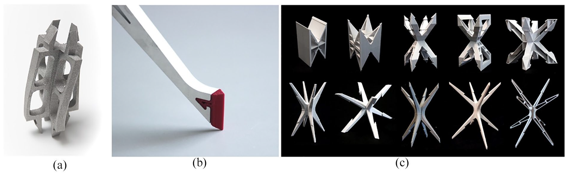
(a) Center joint made by metal 3D printing, (b) hybrid fabrication using ABS end cap and metal leg for easier disassembly, and (c) unit block study based on the snap-interlock performance.
The constructed prototypes presented in this study promise various practical applications. For example, reconfigurable walls and canopies can be built for easy assembly and disassembly. The portal frames explored in this study can incorporate a diverse array of infill elements, such as vertical planters for urban farming (Figure 13(a)) or rain screen panels (Figure 13(b)), advancing the modularity of the stacking system. The proposed snap-interlocking system can also be applied to façade shading (Figure 14(a)) and roof structures (Figure 14(b)) for temporary use. The absence of a bonding agent in the proposed system also provides potential to integrate advanced robotic construction systems with minimal human intervention (Figure 14(c)).
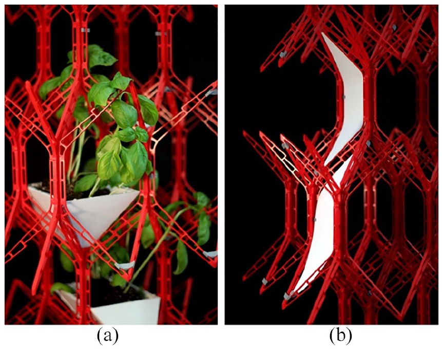
Applications using the modularity of the stacking system: (a) Green wall assembly. (b) Shading surface integration.
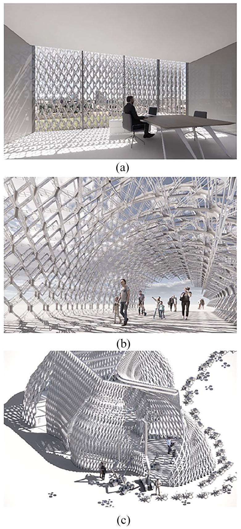
Potential applications for SIMS prototype: (a) Building envelope system. (b) Temporary pavilion structure. (c) Construction automation system by robot agents.
The proposed Snap-Interlock Module System aim to respond to the rise of eventful and temporary architecture in contemporary urban environments. Our research explores a potential alternative construction method which can be completed through non-skilled labor. This unique part-to-whole system is based on the innovation of the part, with a novel snap-interlock mechanism taking advantage of the elastic properties of structural materials. Based on the built prototypes using PLA and steel, further studies on geometry and structural analysis will provide broader applications for reconfigurable structures, allowing Snap-Interlock Module System to contribute to the broader sustainability of our built environment.
Footnotes
Declaration of conflicting interests
The author(s) declared no potential conflicts of interest with respect to the research, authorship, and/or publication of this article.
Funding
The author(s) disclosed receipt of the following financial support for the research, authorship, and/or publication of this article: The research is funded by AISC (American Institute of Steel Construction) and ACSA (Association of Collegiate Schools of Architecture) through Forge Prize Stipend. We thank the SMART Start Fund by University at Buffalo and the Design That Educates Award Stipend by Laka Foundation and Solarlux GmbH. Buffalo Manufacturing Works provided the consultation and support for metal 3D printing.