
Abstract
The article deals with material testing for the research of shell timber structures constructed using active bending. These structures belong to a category in which the elastic properties of the material are directly involved in the construction process during the design stage. It is therefore essential to determine the material properties that govern both the elastic capacity of the material (modulus of elasticity) and the structural resistance (flexural strength). The paper presents the standardized procedure for determining flexural strength by means of a four-point bending test, carried out on 41 pine specimens with a cross-section of 10 × 40 mm. The results of this test serve as calibration data for the numerical models of ongoing research on active bending at the Slovak University of Technology. Within this framework, experimental testing represents a fundamental requirement for numerical model verification, encompassing both material testing and investigations performed on a scaled experimental shell model. The tests provide the mean flexural strength, the 5th percentile, and the characteristic flexural strength. The results indicate that the value of characteristic flexural strength, after applying the relevant correction factors, may reach up to more than twice as low as the minimum flexural strength obtained from the four-point bending test. The aim of the article is, in addition to obtaining the necessary material parameters, to highlight the potential to increase design efficiency by utilizing the full capacity of the material through knowledge of its actual properties.
Introduction
The four-point bending test is the standard procedure used to determine the flexural strength of materials. For the purposes of active bending in timber shell structures, where the ability of the material to undergo elastic forming is essential, the ratio between flexural strength and Young’s modulus is a critical parameter.1,2
Within the current research on active bending carried out at the Slovak University of Technology in Bratislava, a correct determination of flexural strength and modulus of elasticity according to standardized procedures is required to verify numerical models against experimental data. This study therefore focuses on measuring the flexural strength of timber laths with a cross-section of 10 × 40 mm in accordance with EN 408. 4 These results are then used to back-calibrate numerical models, which are compared with the experimental model (Figure 1) of an actively bent grid shell tested in the university’s laboratory conditions. Various specifications for the numerical model are provided in Herda et al. 5
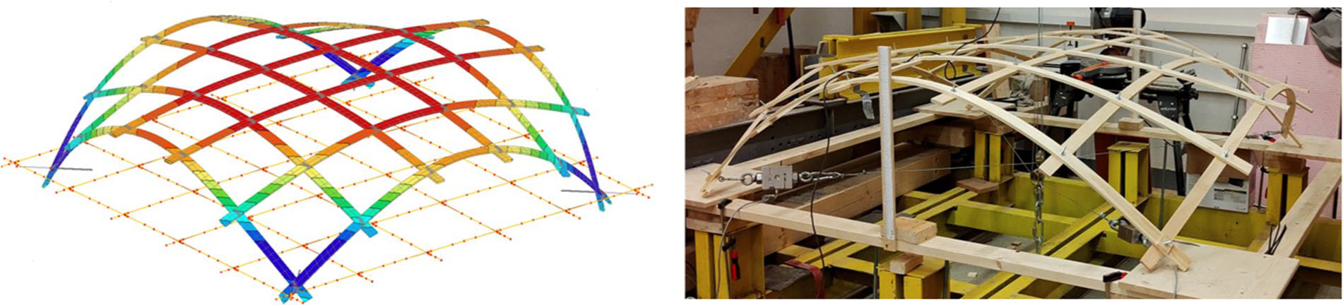
The numerical and experimental model of active bending gridshell at the Slovak University of Technology.
One of the disadvantages of creating the curved geometry of a shell structure by means of the active bending method is the residual stress 6 introduced into the members already during the assembly stage of the structure. For this reason, only such materials can be considered suitable for active bending that, in addition to their ability to undergo elastic deformation, also provide a sufficient reserve of structural resistance. Based on several documented case studies of existing structures (Figure 2), it has been demonstrated that timber is such a material. However, its limitations must be recognized in the design process. Correct determination of flexural strength and modulus of elasticity is therefore crucial for structures formed through elastic shaping.
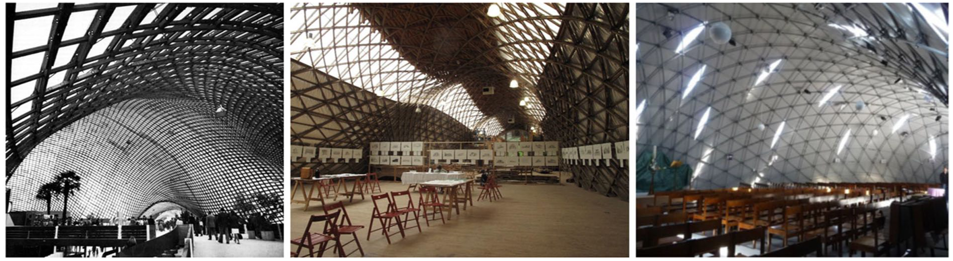
Mannheim Multihalle, Downland Gridshell, Ephemeral Cathedral of Créteil. 3
According to Lienhard et al., 2 this ratio should be equal to or greater than 2.5. Referring to the table of material properties for timber defined in EN 338, 7 the ratio for sawn timber of strength classes C14–C50 ranges from 2.0 to 3.125. Timber as a building material thus operates close to the boundary of its applicability for this type of structures. The aim of this paper is to highlight the differences between timber strength values obtained from the four-point bending test and those recalculated to characteristic strengths, as designers often have only tabulated characteristic values of flexural strength at their disposal.
The aim of the paper is to experimentally determine the flexural strength of thin pine lamellas by means of four-point bending tests and to interpret the obtained values in relation to standard characteristic strength assessment. The contribution of the paper lies in providing application-oriented material data for slender timber elements considered for active bending, with emphasis on the discrepancy between measured and design-oriented strength values.
Materials and methods
The four-point bending tests were conducted in accordance with EN 408, which is based on ISO 8375. 8 EN 384 9 specifies that to determine the characteristic values of mechanical properties obtained from test specimens, the number of test specimens in a single selection must be at least 40.
Based on a visual assessment of quality (straightness of the sample, twisting, growth defects, cracks) among material samples, the research study was conducted using a single selection of wooden specimens with cross-sectional dimensions of 10 mm × 40 mm. Grading using a machine according to STN EN 14081-2 10 or visual grading according to STN EN 1912 11 was not performed within the tests.
The test setup was designed to allow free rotation of the sample at the support points. The load was applied at one-third span intervals, and the deformation was recorded at the mid-span on the tensile edge of the sample (Figure 3). The distances between the supports and loading points were determined according to the cross-sectional dimension ratios specified in EN 408.
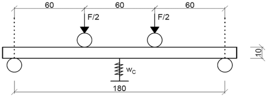
Assembly scheme for the four-point bending test.
EN 408 does not explicitly define the loading rate for the sample; however, it states that the sample should be loaded at a constant displacement rate of the loading heads so that the maximum load is reached within 300 ± 120 s. To determine an appropriate loading rate, 11 preliminary samples were tested in the first stage. The loading rate was set to 3 mm/min based on calibration tests. Since most of the preliminary tests resulted in failure within the desired time range, their results are included in this study and used for the evaluation of the characteristic strength. To determine the characteristic strength of the material, which represents the test value below which 5% of the test results fall, it is first necessary to calculate the bending strength of each sample according to equation (1).

where fm—bending strength, W—the section modulus, A—cross sectional area, and Fmax—maximum applied force reached during testing.
STN EN 408 specifies that, when determining the global modulus of elasticity of wood, the square of the correlation coefficient in the regression analysis,12,13 based on the load–deformation curve, shall be greater than 0.99.
The modulus of elasticity can be calculated from the linear portion of the load–deflection curve using the following relationship (2):
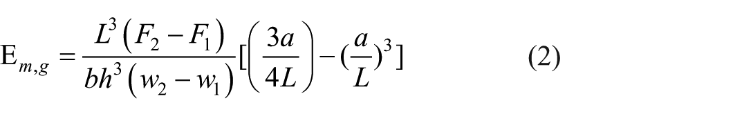
where F2 − F1—increment of load in Newton within the linear portion of the load–deformation curve, w2 − w1—the corresponding increment of deformation, L—the distance between the supports of the test setup, a—the distance between the point of load application and the nearest support, and b and h—the cross-sectional dimensions.
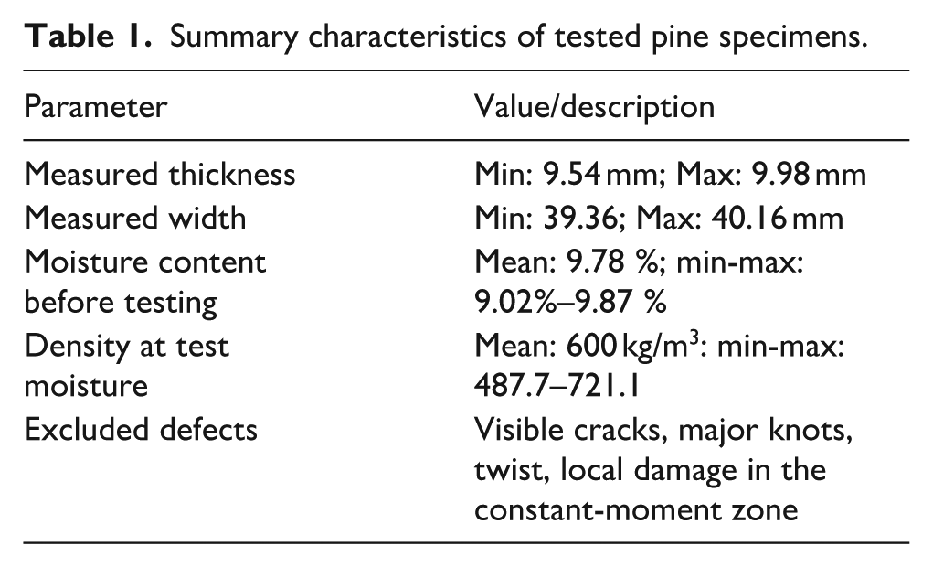
The specimens were prepared from pine timber and visually pre-selected before testing to reduce the influence of natural defects on the measured bending response. Pieces with visible cracks, major knots, pronounced fiber deviation, or significant twist in the critical bending zone were excluded. Moisture content was measured prior to testing, and density was determined from the measured dimensions and mass where available. Since the slope of grain was not quantified separately, grain orientation was assessed only visually. Therefore, the specimen set is described by summary characteristics rather than by individual listing of all tested pieces (Table 1).
Summary characteristics of tested pine specimens.
Results and discussion
Test results
Based on the parameters of the test setup (Figure 3) defined in EN 408, a setup for performing four-point bending tests was prepared. Along with calibration tests, a total of 41 four-point bending tests (Figure 4) were conducted to determine the characteristic bending strength. During the measurements, the maximum deformation reached before specimen failure was also monitored. The obtained deformation data could additionally be used to determine the global modulus of elasticity, as described in more detail in Herda. 14
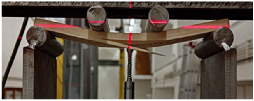
Failure of the specimen in the four-point bending test.
The testing of the specimens was divided into four stages, with sample designations K1-K11, L01-L10, LD01-L10, and M01-10. For all specimens, the correlation coefficient was verified using linear regression, achieving a value of 0.99 or higher. The test results, along with the duration of the test for each specimen, are presented in Table 2.
Evaluation of test results.
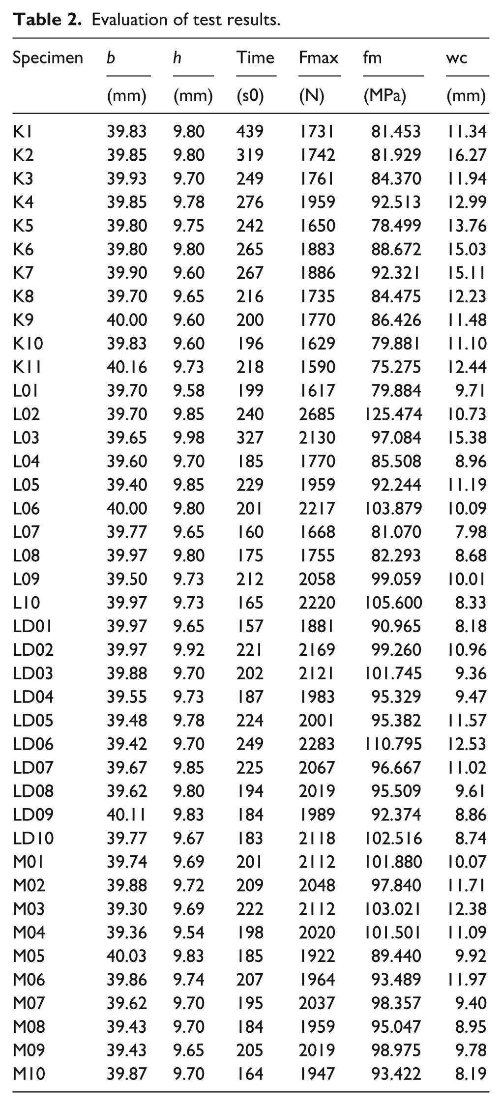
Based on the results shown in the table, it can be concluded that the failure time for specimens K1, L07, L08, L10, LD01, and M10 falls outside the range of 300 ± 120 s specified by standard EN 408. Therefore, these specimens were recorded in the test report.
Post-failure view of specimen LD10 (Figure 5) tested in four-point bending. Failure occurred in the constant-moment region, with crack propagation following a locally deviated fiber path in the tension zone. The observed fracture pattern illustrates the influence of non-uniform fiber orientation on the bending failure mechanism.
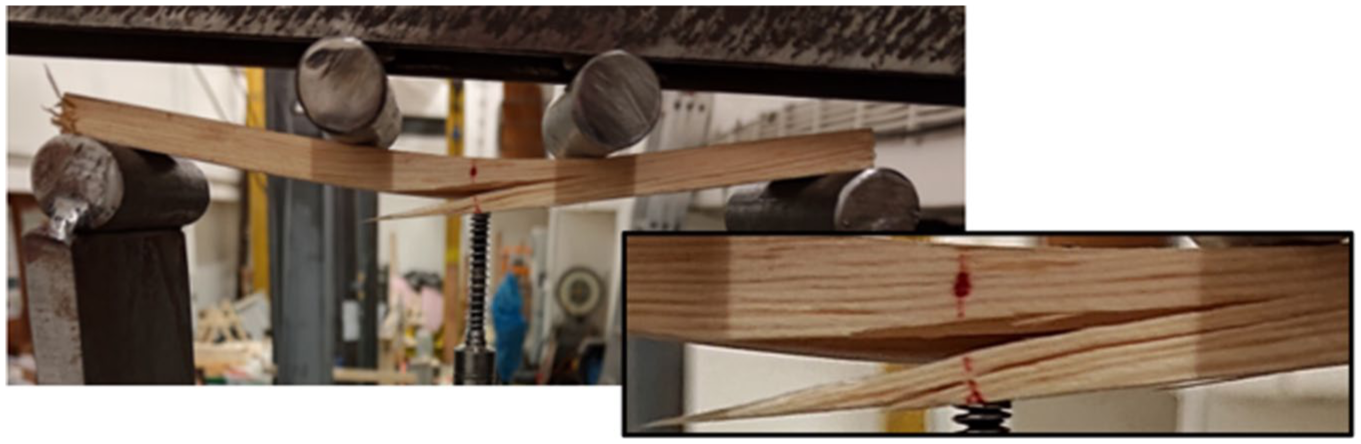
Failure of specimen LD10 after the four-point bending test.
The graphical dependency of Force–Deformation during the tests for all sample groups is shown in Figure 6. All tests exhibited a direct elastic branch without unexpected failures or fluctuations during testing. The maximum forces at which the specimens failed ranged from 1590 N to 2685 N.
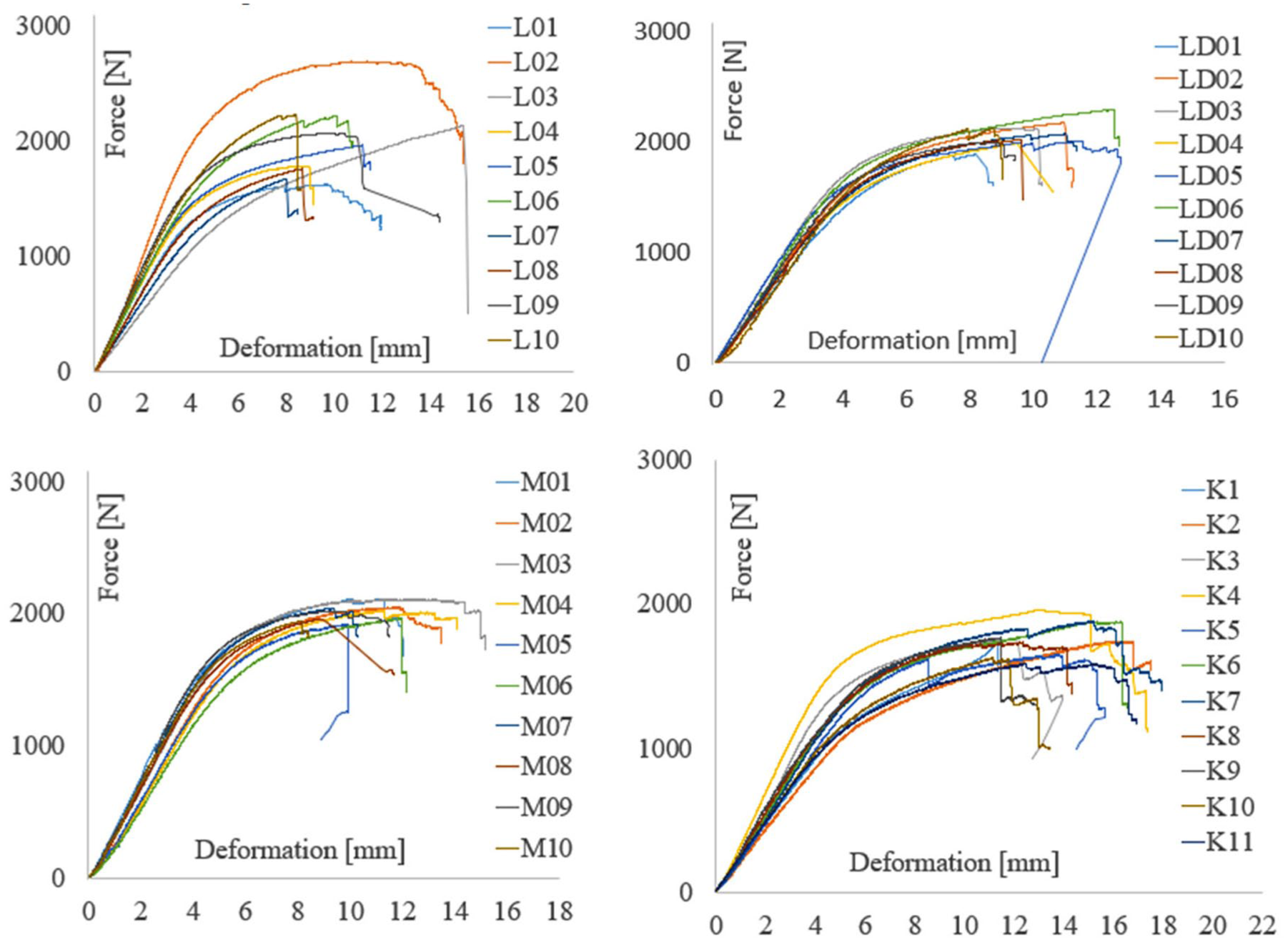
Graphical dependency of Force–Deformation during the tests for all sample groups.
The test results related to bending strength were evaluated based on quartiles using the statistical representation. The evaluation indicated that one sample, L02, is located outside the Q3 quartile, which represents the value below which 75% of the data are found. Due to the exceptional nature of the bending strength of sample L02, this sample is excluded from the overall evaluation of mean and characteristic strength.
Based on the results, the test value f0.05, below which 5% of the test results fall, was determined, along with the mean flexural strength fmean.


According to EN 384, 9 the 5% quantile of flexural strength is adjusted to a height or width of 150 mm by dividing it by the factor kh.
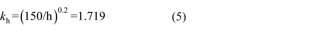
The factor kh accounts for potential defects in larger cross-sections, such as knots or microcracks. Smaller cross-sections represent a lower risk of such imperfections. For this reason, tests on specimens with smaller depths generally yield higher flexural strength values than tests on specimens with larger depths.
In addition to the influence of cross-sectional depth, the standard EN 384 also requires consideration of the number of specimens and the number of samples through the factors kv and ks. For specimens with a flexural strength higher than 30 MPa, the factor kv may be taken as 1.0. In the experiment carried out with a single sample and 40 specimens, the factor ks was approximately 0.76. Based on the above coefficients, the characteristic value of flexural strength can be determined using equation (6).

Using equation (6), the characteristic strength of pine wood tested under laboratory conditions was determined to be 35.28 MPa. When classified into strength classes, this value corresponds to timber of class C35.
An evaluation of the key results obtained by the standardized procedure and through experimental measurements is presented in Figure 7.
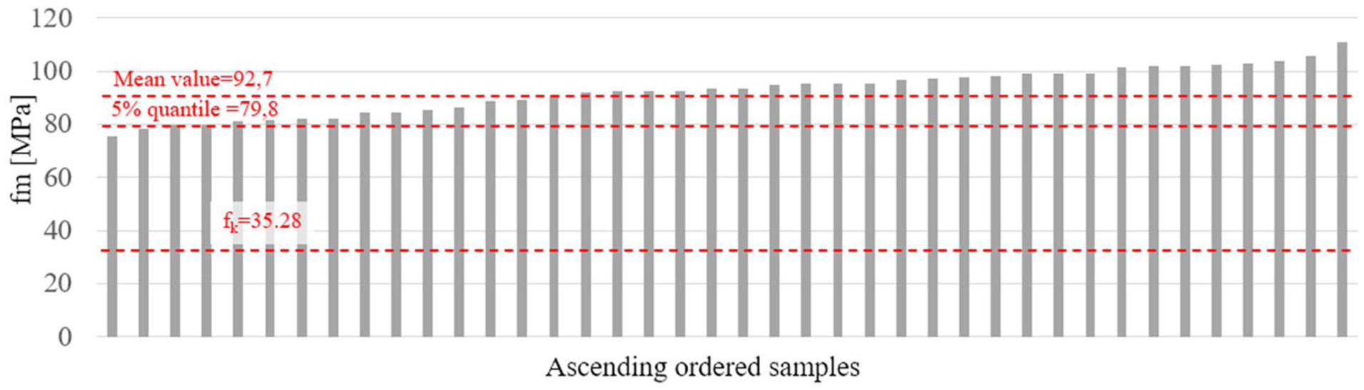
Graphical evaluation of the bending strengths of the samples.
From the evaluation shown in Figure 7, it can be observed that if the design of elastically shaped structures were based on the material properties corresponding to strength class C35 with a flexural strength of 35 MPa, the flexural resistance capacity of timber laths with a cross-section of 10 × 40 mm would be underestimated by more than a factor of two.
Discussion
Based on the results, it can be seen that after applying the correction factors, the 5% quantile flexural strength value of 79.8 MPa is reduced to approximately 35 MPa when calculating the characteristic value of flexural strength. The characteristic strength value represents the starting point for engineers in the design of timber structures. This value cannot be neglected in the design process and is an essential part of a proper structural assessment. However, if the design of structures constructed by means of active bending were based solely on the characteristic flexural strength, it would not be possible to fully exploit the potential of elastic shaping of timber.
In the context of active bending, the results of the bending strength tests can be further used to examine timber lamellas of greater length, or a simple rod grid (Figure 8), and to monitor the maximum achievable radius of curvature until the bending strength limit, ranging from 75 to 125 MPa, is reached.
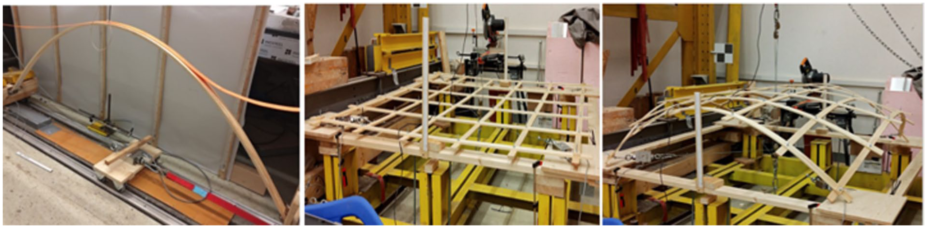
Bending of a timber lamella and a simple rod grid.
An advantage of structures built using active bending method is the utilization of two- or multi-layered cross-sections (Figure 9). However, for further research it is worth considering up to what strength levels the elastic branch of the bending test load–deflection curve extends.
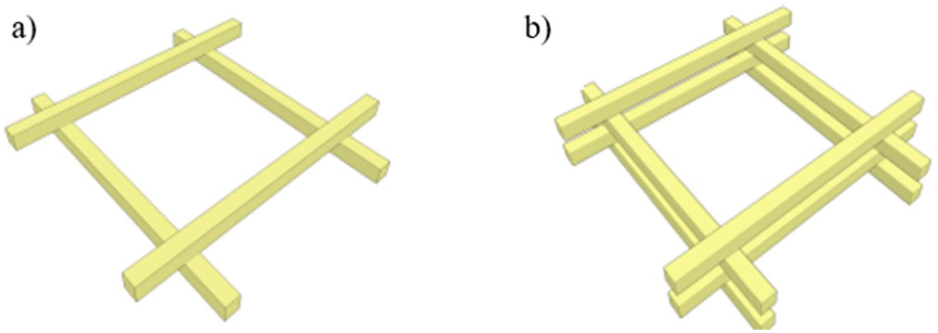
Single-layer and double-layer rod assembly. 15
In this type of cross-section, connections are applied in such a way that the joints remain untightened during the shaping process, allowing the wooden laths to slide along their longitudinal axes. With this type of connection, the double-layer rod assembly behaves during shaping similarly to a single-layer assembly with a simple cross-section, thus exhibiting lower flexural stiffness. Once the final geometry is reached, the joints are tightened, forming a composite cross-section with a significantly higher flexural stiffness EI. If the composite section is formed efficiently, this increase may exceed a factor of 26. 16
This highlights the importance of knowing the true flexural strength of bent timber, as it can enhance design capacity for both small curvature radii and residual strength evaluation, thereby improving efficiency compared to the automatic use of characteristic values in design.
Despite this approach during the forming of the structures, failures may occur at the connection locations once the bending strength of the timber laths is exceeded. This increases the demand for accurate knowledge of these parameters, as even in the presented results for laths with a cross-section of 10 × 40 mm, the variability of strength properties ranged from 75 to 125 MPa.
Conclusions
The presented paper describes the standardized procedure for determining flexural strength values by means of the four-point bending test. A total of 41 tests were carried out on pine specimens with a cross-section of 10 × 40 mm. The evaluation yielded a 5% quantile value of 79.8 MPa, a mean flexural strength of 92.7 MPa, and a characteristic strength of 35.28 MPa. The calculation of characteristic strength follows the standardized procedure, where the 5% quantile is divided by the size factor kh. This approach produces a value that accounts for potential defects in larger cross-sections, such as knots or microcracks. However, smaller cross-sections represent a lower risk of such imperfections, which is why the characteristic strength value is more than twice lower than the minimum flexural strength obtained from the four-point bending test. This is therefore a case in which characteristic flexural strength values may lie well below the actual strength of the material. By understanding these relationships and knowing the true flexural strength values, it is possible to increase the efficiency of designing actively bent timber grid shell structures.
Although at first glance it may appear that bending timber introduces excessively high stress levels into the structure, thereby limiting its reserve capacity for loads acting during the service life the formation of a double-layered cross-section can provide a significant increase in the structural resistance reserve.
The obtained results demonstrate the advantages of constructing actively bent structures using cross-sections with low height, due to their increased bendability. The low cross-section height also facilitates the qualitative selection of timber and minimizes defects and natural irregularities that may occur in the wood. Additionally, according to standard design procedures, the strength of low-height cross-sections can be increased using the kh factor, which in this specific case would correspond to a multiplier of 1.72 compared to the tabulated value for C35 timber. However, Eurocode 5 limits this factor to 1.3. Nevertheless, this still represents a significant increase in the allowable strength.
Footnotes
Declaration of conflicting interests
The authors declared no potential conflicts of interest with respect to the research, authorship, and/or publication of this article.
Funding
The authors disclosed receipt of the following financial support for the research, authorship, and/or publication of this article: This paper has been supported by the Scientific Grant Agency of the Ministry of Education, Science, Research and Sport of the Slovak Republic and the Slovak Academy of Sciences – VEGA grant 1/06377/25.
The project could also be created thanks to internal grant of SvF STU, the program for motivation and support for increasing the quality and efficiency of the scientific and research activity of young scientific and research workers 2023 – grant 1607.
Data availability statement
All relevant data and results are presented in the main body of the article and can be supported by the original measurement records available in Excel format upon request.