
Abstract
This paper presents an integrated approach to the design, fabrication, and structural analysis of wide-spanning concrete structures by combining bending-active formwork with conformal 3D printing. Traditional large-scale additive manufacturing in construction is constrained by horizontal layer deposition, limiting applications to vertical elements such as walls. To extend 3D printing capabilities to roofs, floors, and other spanning elements, this study proposes using elastically deformed timber strips as lightweight formwork substrates onto which concrete is robotically deposited along non-planar, structurally informed toolpaths. The methodology is validated through a systematic experimental campaign progressing from material characterization and small-scale tests to a full-scale prototype spanning 4.6 meters. Complementing the physical investigations, a voxel-based finite element simulation framework is developed to evaluate the influence of toolpath strategies and interlayer timing on structural stability during the printing process. Results demonstrate that toolpaths aligned with the global span reduce formwork buckling and promote uniform stress distribution, while short interlayer pauses enhance printing stability. This research contributes a novel fabrication and analysis framework for sustainable, material-efficient construction of curved, long-span architectural elements.
Keywords
Introduction
The building and construction sector poses one of the most pressing environmental challenges of our time. Buildings are responsible for approximately 34% of global CO2 emissions, with embodied carbon from building materials contributing 2.9 gigatons annually. 1 Cement production, which serves as the primary binder in concrete, accounts for roughly 7% of all anthropogenic carbon emissions worldwide.2,3 Simultaneously, the global housing crisis intensifies, with over 1.6 billion people lacking adequate shelter. 4 Meeting this demand through conventional methods would further exacerbate environmental degradation, underscoring the need for approaches that reconcile increased building production with reduced material consumption.
Large-scale 3D printing has emerged as a promising technology for addressing both challenges. By depositing material only where structurally needed, additive manufacturing minimizes waste, and pioneering projects by ICON and PERI have demonstrated the viability of 3D printing entire residential structures.5,6 However, nearly all current systems rely on three-axis gantry platforms that deposit material in horizontal layers, which inherently limits their application to vertical building elements such as walls and columns. These systems can typically accommodate overhangs of no more than approximately 17.5 degrees from the vertical, and attempts to print inclined surfaces produce stair-stepping effects that compromise both surface quality and mechanical performance. 7 As a result, essential spanning elements such as roofs, floor slabs, and vaults must still be constructed using conventional labor- and material-intensive methods, often making them the most expensive components of a building project.
This raises a fundamental question: can 3D printing principles be applied to wide-spanning horizontal structures? Addressing this requires overcoming two challenges: developing a formwork system that supports curved concrete deposition without conventional molds, and adapting the printing process to deposit material along non-planar paths following the substrate geometry.
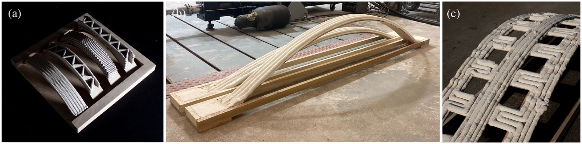
Bending-active structures offer an elegant solution to the first challenge, exploiting large elastic deformations of initially straight elements to generate complex curved geometries. 8 When thin, flexible strips of materials such as carbon fiber reinforced polymer (CFRP) or timber are bent and assembled into grid configurations, they naturally assume structurally efficient shapes that are well-suited for shell-like applications. Prior research has demonstrated the potential of using such structures as formwork for concrete construction. Cuvilliers et al. 9 developed a prototype combining a bent fiberglass gridshell with a fiber-reinforced concrete envelope, demonstrating that the cured concrete braced the flexible formwork against in-plane shear while the gridshell provided the funicular shape. As shown in Figure 1, Schleicher and Herrmann 10 extended this concept by constructing a hybrid gridshell from CFRP strips onto which concrete was manually applied, demonstrating remarkable load resistance. A key finding was that as the concrete cured, initial layers bonded with the formwork and reinforced the system, allowing additional material to be added as the formwork became progressively stiffer over time. Yavaribajestani et al.11,12 further investigated the cross-sectional behavior and parameter sensitivity of such hybrid systems, establishing that stay-in-place CFRP formwork significantly enhances the flexural strength and stiffness of concrete gridshells.
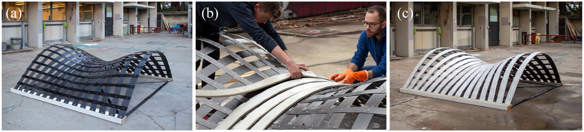
(a) Full-scale CFRP formwork, (b) manual concrete application, and (c) finished hybrid gridshell. 10
Conformal 3D printing addresses the second challenge by allowing the extruder to follow toolpaths with continuously varying vertical coordinates, conforming to the geometry of a curved substrate. 13 This approach eliminates the stair-stepping artifacts and weak interlayer connections inherent to planar printing on curved surfaces, and it enables the alignment of deposited material with structural force vectors. 14 When combined with multi-axis robotic platforms, conformal printing provides the degrees of freedom necessary to maintain optimal nozzle orientation across complex surfaces.
Building upon these foundations, this paper presents a novel methodology combining bending-active formwork with conformal 3D printing for wide-spanning concrete structures, validated through experiments spanning material characterization to full-scale implementation. In parallel, a voxel-based finite element simulation framework investigates the structural implications of toolpath strategies and interlayer timing during fabrication, providing both practical guidance and a theoretical foundation for advancing this construction method.
Proposed fabrication method
Bending-active formwork
The proposed fabrication method centers on using bending-active structures as both formwork and potential supplementary reinforcement for robotically deposited concrete. In this context, bending-active formwork refers to thin, elastically deformed elements that are assembled in a flat or slightly curved state and then bent into their target geometry by adjusting boundary conditions. 8 The elastic energy stored in the material keeps the system in equilibrium, producing smooth, naturally curved surfaces without the need for custom-shaped molds or extensive falsework. A distinctive advantage is the dual function of the formwork: it provides the substrate for concrete deposition during fabrication and, once cured, remains as stay-in-place reinforcement, eliminating the need for formwork removal and reducing both labor and waste. The concept is applicable to various formwork materials, including CFRP composites and timber, with timber offering advantages in cost, availability, and sustainability. As illustrated in Figures 1 and 2, this study uses softwood and plywood strips as the primary formwork materials, building on the research lineage that began with CFRP-based hybrid gridshells and extended to timber-based systems in subsequent investigations. 10
Comparison of (a) conventional planar 3D printing requiring support material and creating stair-stepping effects versus (b) proposed conformal 3D printing on bending-active formwork eliminating support material through multi-axis deposition.
Conformal 3D printing
Conformal 3D printing represents a fundamental departure from conventional layer-based additive manufacturing, where objects are sliced into horizontal layers and material is deposited at a fixed vertical coordinate. While effective for vertical elements, this strategy introduces severe limitations for curved or spanning structures: inclined surfaces suffer from stair-stepping artifacts that degrade surface quality and weaken interlayer bonds, while cantilevered regions collapse under the weight of freshly deposited material.7,15 Conformal printing overcomes these constraints by allowing the extruder to follow non-planar toolpaths that conform to the geometry of an underlying substrate. As compared in Figure 2, material is deposited directly onto the curved formwork surface, with each subsequent layer offset conformally rather than horizontally. This alignment of print paths with the substrate geometry eliminates the need for support material and enables the deposition direction to follow structural force vectors, potentially improving the mechanical performance of the finished element.
By combining conformal 3D printing with bending-active formwork, the approach can be extended beyond vertical walls to wide-spanning architectural elements such as roofs and lightweight floor slabs, as envisioned in Figure 3. Realizing this vision introduces specific technical requirements in three areas: toolpath generation, formwork registration, and hardware configuration. The toolpath generation challenge is addressed through a custom Grasshopper plugin called BarkBeetle, which converts the strip intersection network of the formwork into continuous skeleton graphs that define non-intersecting print paths. 16 Formwork registration requires accurate knowledge of the as-built formwork geometry, which may differ from the digital model due to fabrication tolerances and elastic deformation under self-weight. Hardware requirements are met through a multi-axis robotic platform that provides sufficient degrees of freedom to maintain the extrusion nozzle perpendicular to the formwork surface at all points along the toolpath.
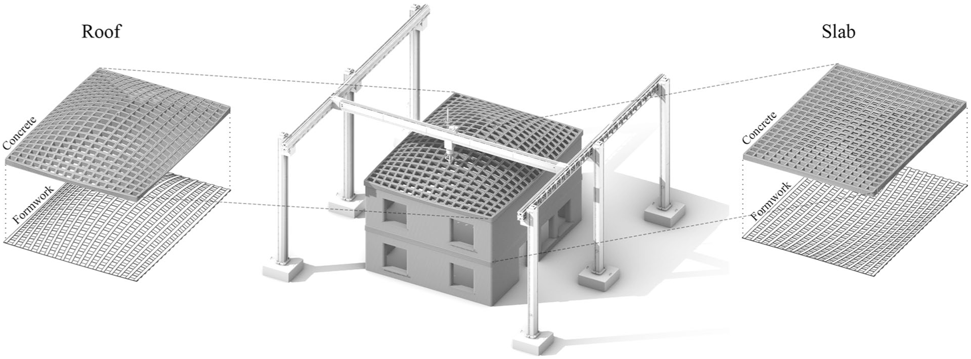
Envisioned architectural applications of conformal 3D printing on bending-active formwork, extending additive manufacturing beyond vertical walls to wide-spanning roof structures (left) and lightweight floor slabs (right).
Multi-axis robotic platform
To meet the hardware requirements outlined above, this research employs a multi-axis robotic platform that combines a six-axis industrial robot with a linear motion track, creating a seven-axis system suitable for architectural-scale elements. The linear axis extends the reachable volume across formwork assemblies spanning several meters, while the six rotational axes enable perpendicular nozzle orientation at every point along the toolpath, essential for uniform material deposition and optimal bonding. Two robotic configurations were used over the course of this research: a KUKA KR16-2 robot for the small-scale experiments and a larger KUKA KR 210 R3100 robot mounted on a KUKA KL 1500/3 linear track at the Print4D facility in Prague for the full-scale prototype. Concrete was mixed and pumped using an IMER Small 50 system for the smaller experiments and a MAI Multimix system at full scale, both using Sikacrete-752 3D micro-concrete as the printing material.
Experimental investigations
A systematic three-tiered experimental program was conducted to validate the proposed fabrication framework, building on methods first presented in two companion conference papers.17,18 The investigations progressed from material characterization through intermediate-scale tests to a full-scale prototype, with each stage building upon the previous findings to identify challenges, establish design guidelines, and develop a coherent workflow for architectural-scale applications.
Material characterization
The first experimental series investigated the composite behavior of timber and concrete elements, extending prior research on CFRP-concrete hybrid systems to evaluate the viability of softwood as a bending-active formwork material for printed concrete layers. 14 The composite system consisted of fir timber serving as the primary tension element and Sikacrete-752 3D micro-concrete providing the compression layer, with Sikadur 32 Hi-Mod epoxy adhesive bonding the two materials. Individual material properties were characterized through tensile and bending tests on softwood specimens following ASTM D143-23 and compressive strength testing of 7-day concrete cylinders per ASTM C39/C39M-24. Timber testing revealed an average tensile strength of 63 MPa with elastic modulus values ranging from 5581 to 9852 MPa.
Composite beam specimens were fabricated using both 3D printing and conventional casting methods, then tested under four-point bending, as shown in Figure 4. Three specimen groups were prepared: Group A with 3D printed concrete layers, Group B with cast concrete on nine-inch span specimens targeting 84.6 kN ultimate load capacity, and Group C with cast concrete on 18-inch span specimens to explore shear behavior. A notable discrepancy emerged between fabrication methods, with cast specimens achieving only 9 MPa compressive strength compared to 29.6 MPa for printed specimens, attributable to differences in concrete age between the two batches.
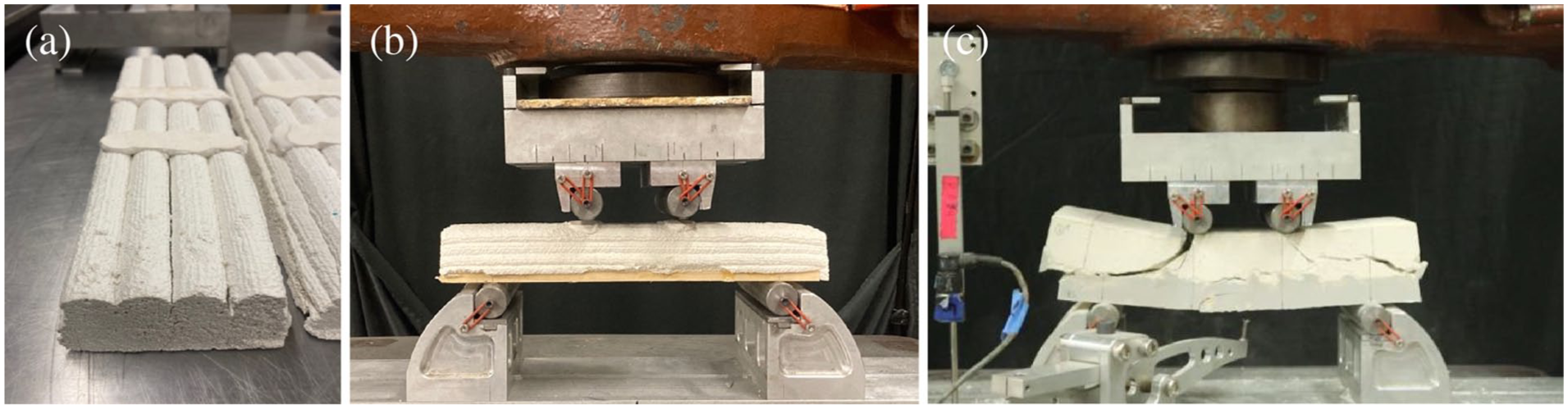
Flexural testing of hybrid timber-concrete specimens with (a and b) 3D printed concrete layers and (c) cast concrete layer, showing diagonal shear failure modes.
Structural testing revealed an unexpected but consistent failure pattern across all specimen groups. Despite the design intent for flexural failure, every composite beam failed through diagonal shear in the concrete layer. Group A specimens reached maximum loads between 28.7 and 35.8 kN, while Groups B and C exhibited lower capacities of 9.5 to 12.8 kN, both falling significantly below predicted values. Load-deflection responses showed initial linear elastic behavior followed by sudden brittle failure, with diagonal cracks propagating at approximately 45-degree angles from supports toward loading points as shown in Figure 4(c). Importantly, the epoxy bond between timber and concrete remained intact throughout all tests, confirming that the adhesive interface maintained effective composite action. The consistent shear failure mode indicated that the absence of mechanical shear connectors between the layers concentrated all shear demands on the concrete alone, creating stress concentrations that initiated premature diagonal cracking. These findings established that while the adhesive bonding concept is valid, the absence of mechanical shear connectors was the primary cause of premature failure across all specimen groups.
Small-scale prototyping
The second experimental series introduced physical and digital experiments to identify key challenges and opportunities for conformal 3D printing on bending-active formwork. Three progressive tests were conducted with increasing geometric complexity. In the first test, clay was printed on 30 cm long, 1 mm thin veneer strips to explore fundamental toolpath designs and infill patterns at a manageable scale (Figure 5(a)). The second test scaled up to concrete printing on single plywood strips (Figure 5(b)), each comprising two glued 3 mm plywood layers with a total length of 2000 mm and width of 100 mm, bent to different curvatures with midspan heights of 222 mm, 305 mm, and 375 mm. The third test extended the approach to a simplified single-curved gridshell consisting of three longitudinal plywood strips connected by six transverse elements (Figure 5(c)). All formwork assemblies were mounted on timber frames to maintain fixed support distances.
Small-scale conformal 3D printing experiments on bending-active formwork: (a) toolpath patterns on single strip, (b) concrete printing on single strips with varying curvature, and (c) multi-strip gridshell configuration.
Toolpath design and formwork registration followed a two-phase digital workflow. Curved formwork geometries were form-found using Kangaroo Physics in Rhinoceros 3D and Grasshopper. Toolpaths and infill patterns for concrete deposition were generated using the custom BarkBeetle plugin, which was developed specifically for conformal 3D printing on strip-based formwork. 16 Accurate formwork registration was achieved by attaching a touch probe to the extrusion nozzle and moving it to multiple locations on the formwork surface. The collected data points were used to digitally reconstruct the as-built formwork geometry, ensuring a constant distance between nozzle and substrate during printing.
For the concrete printing experiments, Sikacrete-752 3D micro-concrete was mixed with 18.5% water by weight and deposited in two 15 mm layers using the KUKA KR16-2 robotic arm, which controlled nozzle orientation to remain perpendicular to the curved formwork throughout the process. Given the 20 mm nozzle width and 100 mm strip widths, each strip was covered in four passes, with print layer spacing established by offsetting toolpaths 30 mm from the formwork surface. Since the thin formwork was particularly susceptible to deflections from asymmetric loading during initial stages of material deposition, a sequenced printing approach was implemented. Printing began at the center strip and proceeded outward to adjacent strips on both sides, ensuring even weight distribution and mitigating buckling risks. Calibrations proved successful across all prototypes, yielding uniform nozzle-to-formwork distance, proper material adhesion, and consistent print path dimensions.
These tests validated the fundamental feasibility of achieving hybrid composite structures through conformal 3D printing on bending-active formwork. However, several challenges emerged that required further development. The touch-probe registration process, while effective, proved time-consuming and involved numerous steps that would compound in complexity with more intricate geometries. Toolpath generation for intersecting cross-members was initially cumbersome, becoming streamlined only through the continued development of BarkBeetle. The critical finding from the material tests that diagonal shear stress represents a primary failure mode for these composite cross-sections highlighted an important consideration that was not yet fully integrated into the design and analysis workflow at this stage.
Full-scale prototype
The third experimental series aimed to validate the fabrication method at an architectural scale relevant to building roofs and floors. Building upon insights from the material tests and small-scale experiments, and informed by prior parameter sensitivity analyses of hybrid gridshells with bending-active formwork, the team constructed a full-scale wide-spanning prototype measuring 4.6 m in length and 2 m in width. 12 The gridshell was elevated on two timber EURO-pallets fitted with custom-made bulkheads designed to accommodate the timber strips and provide structural support at the boundaries, as shown in Figure 6.
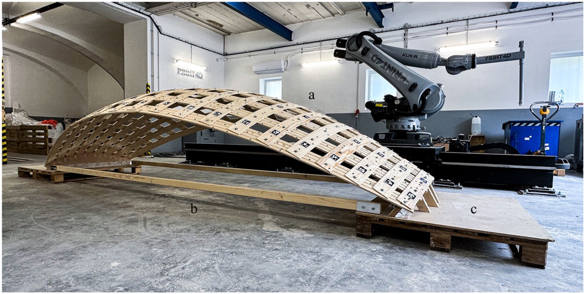
Completed bending-active formwork with 9 longitudinal and 22 transverse timber strips.
Given that this scale exceeded the capabilities of the robotic and pumping equipment used in earlier experiments, the research team partnered with Print4D to utilize their facilities in Prague. The setup included a KUKA KR 210 R3100 robot mounted on a KUKA KL 1500/3 linear track, which significantly expanded the platform reach, and a MAI Multimix pumping system that enabled improved print quality and higher material volumes. The bending-active formwork comprised nine longitudinal spruce strips with a width of 100 mm and thickness of 15 mm, and 22 transverse plywood strips with a width of 100 mm and thickness of 6 mm (Figure 7).
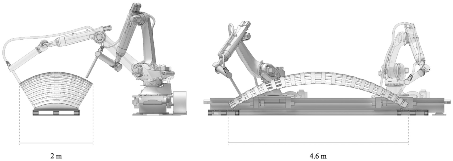
Seven-axis robotic system combining six-axis industrial robot with linear track, enabling comprehensive reach and perpendicular nozzle alignment to bending-active formwork surfaces.
Toolpath design for this complex gridshell geometry utilized the refined BarkBeetle plugin. The method converts user-defined linear networks, derived from the intersection points of formwork strips, into skeleton graphs that represent the printing structure with continuous, non-intersecting paths ensuring process continuity (Figure 8). The plugin generates multiple printing layers using conformal stacking methods that eliminate stair-stepping effects on curved surfaces while offering various options for controlling material deposition parameters.
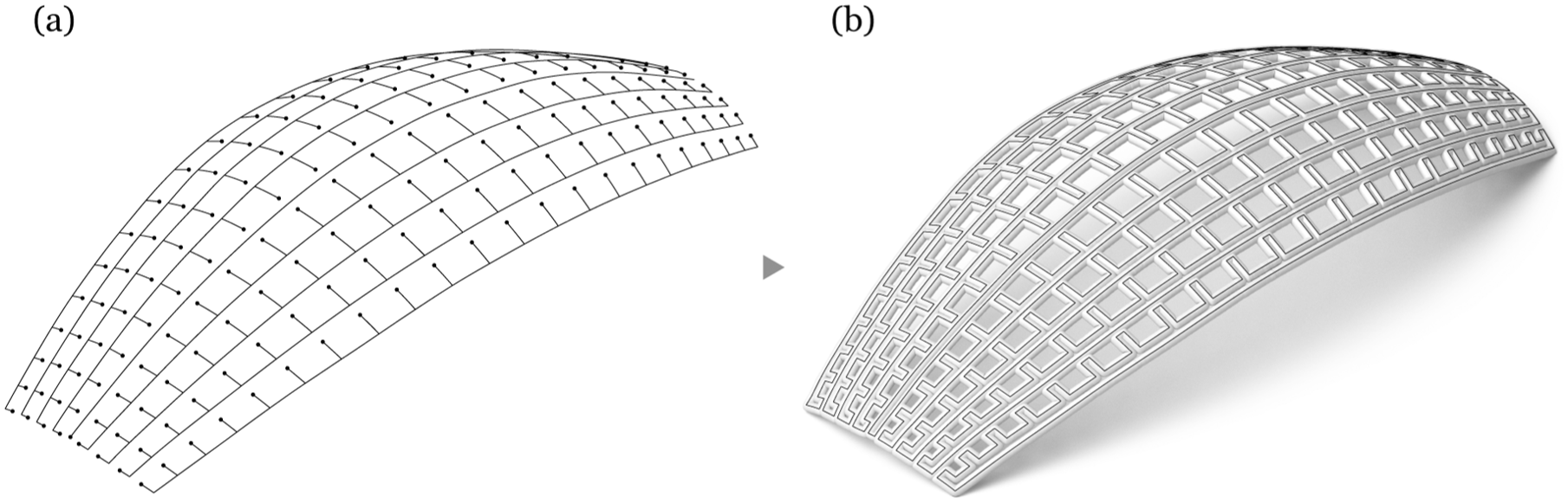
Toolpath design process: (a) skeleton graph generation from strip iso-curves and (b) conversion to multi-layer toolpath with user-defined widths and resolved member intersections.
Two alternative formwork registration methods were explored at this larger scale. The first method employed an Einscan HX handheld scanner that combined LED structured light with blue laser scanning. Its compact size and portability made it well-suited for capturing large objects, and the resulting 3D scan proved highly accurate and reliable, enabling successful toolpath projection and execution during printing. However, the process from initial preparation through mesh cleanup to importing the result into the toolpath design software involved considerable time. The second method utilized vision-based position estimation using ArUco markers as reference points. A ZED 2 stereo camera with an integrated Inertial Measurement Unit (IMU) was attached to the robot arm, enabling real-time tracking of camera position and orientation in three-dimensional space as it traversed the formwork. While this approach occasionally produced duplicate points or inaccuracies under unfavorable ambient lighting conditions, it proved sufficient for reconstructing the strip-based formwork surface geometry (Figure 9).
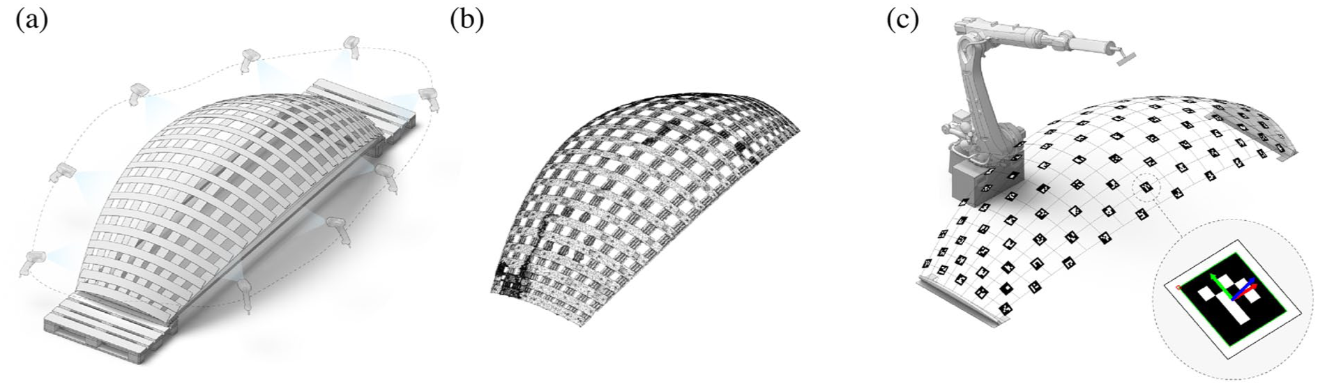
Formwork registration methods: (a) 3D scanning with portable scanner, (b) resulting point cloud and processed mesh for toolpath projection, and (c) vision-based registration using ZED 2 stereo camera with ArUco markers for real-time position tracking.
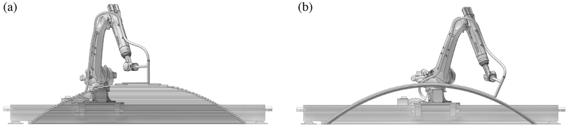
The printing process was designed to apply five consecutive layers of concrete, with each layer strategically sequenced to maintain balanced loading across the formwork structure. As shown in Figure 10, the multi-axis platform maintained perpendicular nozzle orientation throughout the deposition process, achieving uniform concrete distribution across the curved formwork. However, the fabrication encountered a critical failure after the completion of the third layer. The bolts securing the formwork strips to the bulkheads experienced excessive stress and tore out, causing the support conditions to change dramatically. This connection failure led to the structural collapse of the gridshell formwork under the accumulated concrete load. Despite this setback, the experiment yielded important insights: the formwork successfully supported approximately 500 kg of freshly printed concrete before the connection failure occurred, a significant load considering that the material had not yet fully cured at the time of collapse.
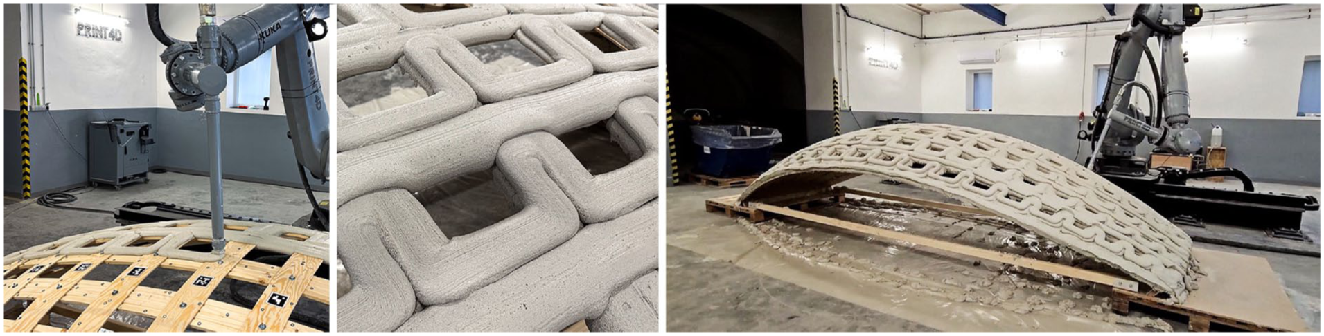
Conformal 3D printing on the full-scale prototype showing the multi-axis robotic platform maintaining perpendicular nozzle orientation for uniform concrete deposition on the bending-active formwork.
Post-experiment structural analysis
Finite element analysis conducted after the physical experiment validated the observations from the fabrication process and revealed critical design insights. Using Alpaca4D with layered quadrilateral mesh voxels representing both the printed concrete (50 mm thickness) and wood formwork (8 mm plywood), a uniform vertical surface load of 1 kN/m2 was applied across the printed shell to simulate typical roof loading conditions. The analysis of the nine longitudinal strip configuration revealed significant stress concentrations in the central region, with tensile stress in the concrete reaching 6.22 MPa and compressive stress in the wood reaching 14.4 MPa, both exceeding typical material capacities. The tensile stress of 6.22 MPa exceeds the typical tensile strength of Sikacrete-752 3D micro-concrete, which ranges from approximately 2 to 4 MPa, highlighting that the linear elastic model used here does not capture the onset of cracking or the redistributions that would follow in practice. This excessive stress concentration resulted from the odd number of longitudinal strips creating a symmetric load accumulation pattern focused on the center strip, directly explaining the physical observations of critical loading conditions that precipitated the connection failure during printing.
When the geometry was digitally modified to use eight longitudinal strips instead of nine, the force distribution became dramatically more uniform. The problematic central stress concentration was eliminated, and both materials remained within their respective capacity limits. This computational analysis demonstrated that an even number of longitudinal strips would have prevented the central load accumulation that ultimately caused the connection failure, illustrating how digital structural analysis can and should inform design decisions early in the process to avoid structural problems during fabrication (Figure 11).
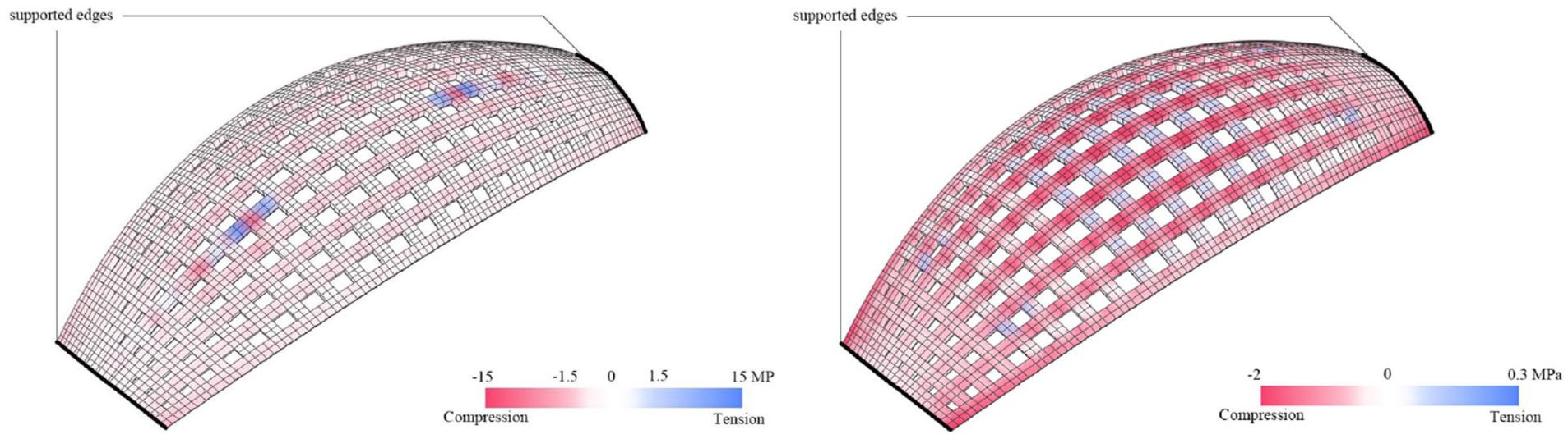
Structural analysis comparing stress concentrations in gridshells with odd (left) versus even (right) numbers of longitudinal strips.
Structural simulation framework
While the experimental investigations provided practical validation of the fabrication concept, understanding the structural behavior of the hybrid system during the printing process requires detailed simulation of the evolving material properties and loading conditions. This section presents a voxel-based finite element framework developed to systematically investigate how different toolpath strategies and interlayer timing affect the structural stability of bending-active formwork during conformal 3D printing.
Simulation methodology
The simulation framework was implemented using Alpaca4D, a Grasshopper plugin built on the OpenSees finite element engine, supporting beam, shell, and brick elements in static and dynamic analyses within a parametric modeling environment.19,20 A voxel-based modeling strategy was adopted to enable material differentiation between the formwork and printed concrete, to represent the layered deposition process, and to assign time-dependent material properties to the concrete as it cures. This approach provides more accurate modeling of the physical bonding between dissimilar materials compared to conventional simulation tools that rely solely on line and shell elements.
The time-dependent elastic modulus of the printed concrete, E(t) in MPa, was defined as a linear function of deposition time t in min, following the relationship E(t) = 0.0395 + 0.001705t, based on established models for early-age 3D printed concrete. 21 The Poisson ratio of concrete was set to 0.3, with the shear modulus derived using standard isotropic elasticity relationships. Wood was used as the formwork material with an elastic modulus of 8000 N/mm2, a Poisson ratio of 0.30, and a shear modulus of 3077 N/mm2. 22 A base printing speed of 20 mm/s was adopted, corresponding to typical concrete extrusion conditions. The framework was applied to three scenarios of increasing complexity: printing on a single bending-active strip, printing on a doubly curved gridshell, and analysis of the full-scale prototype, each under varying toolpath strategies and interlayer time intervals.
Toolpath analysis on a single strip
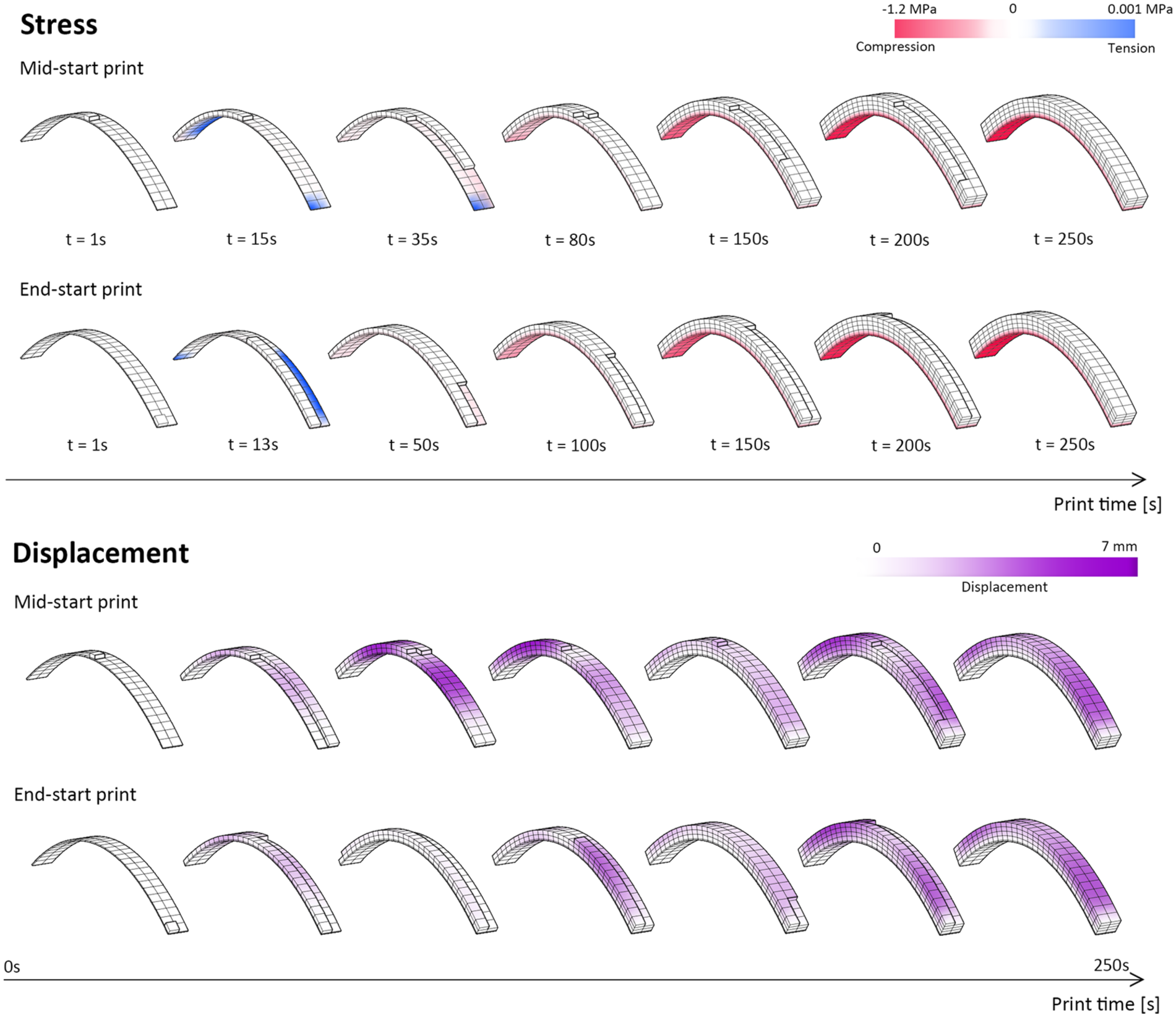
The first simulation scenario examined a simplified geometry consisting of a single wood strip 500 mm long, 40 mm wide, and 5 mm thick, with both ends fixed to simulate support conditions. Concrete was deposited layer by layer using a print path of 20 mm width and 8 mm height, with a total of four layers modeled. Two toolpath starting strategies were compared: a mid-start approach in which printing begins at the center of the strip and proceeds outward, and an end-start approach in which printing begins from one support and advances continuously to the other, as illustrated in Figure 12.
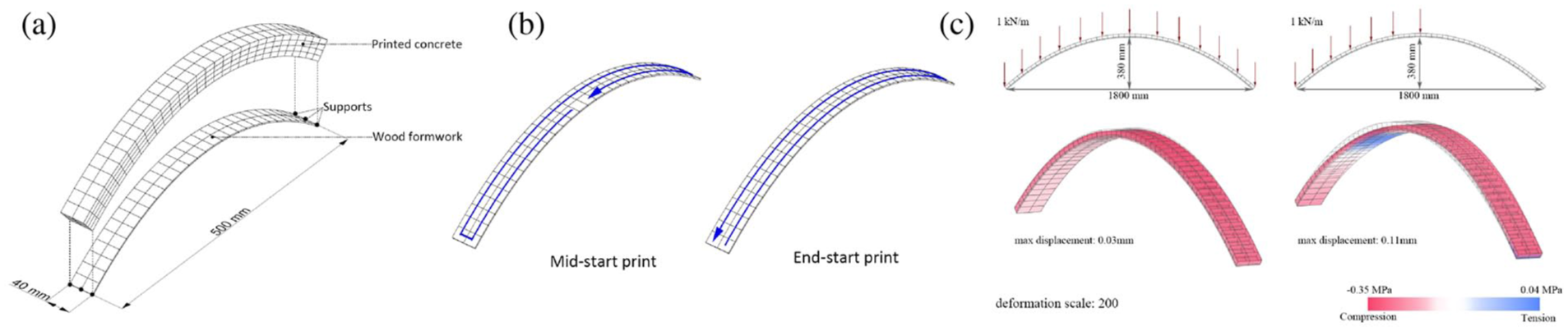
Digital simulation analysis showing (a) mesh representation of hybrid strip, (b) printing sequence scenarios comparing end-start and mid-start approaches, and (c) stress analysis under symmetric and asymmetric loading conditions.
The simulation results revealed that the printing sequence of the toolpath significantly influences the structural behavior during printing (Figure 13). Both concrete and wood experienced increasing compressive stress as the structure built up, though a brief tensile spike appeared in the wood at the start of mid-start printing when the formwork carried most of the load. The end-start condition produced shorter, smaller displacement cycles, while the mid-start strategy led to longer cycles with larger peaks due to asymmetric loading. As material distributed more evenly, the formwork transitioned to a stable compressive state, as shown in Figure 14.
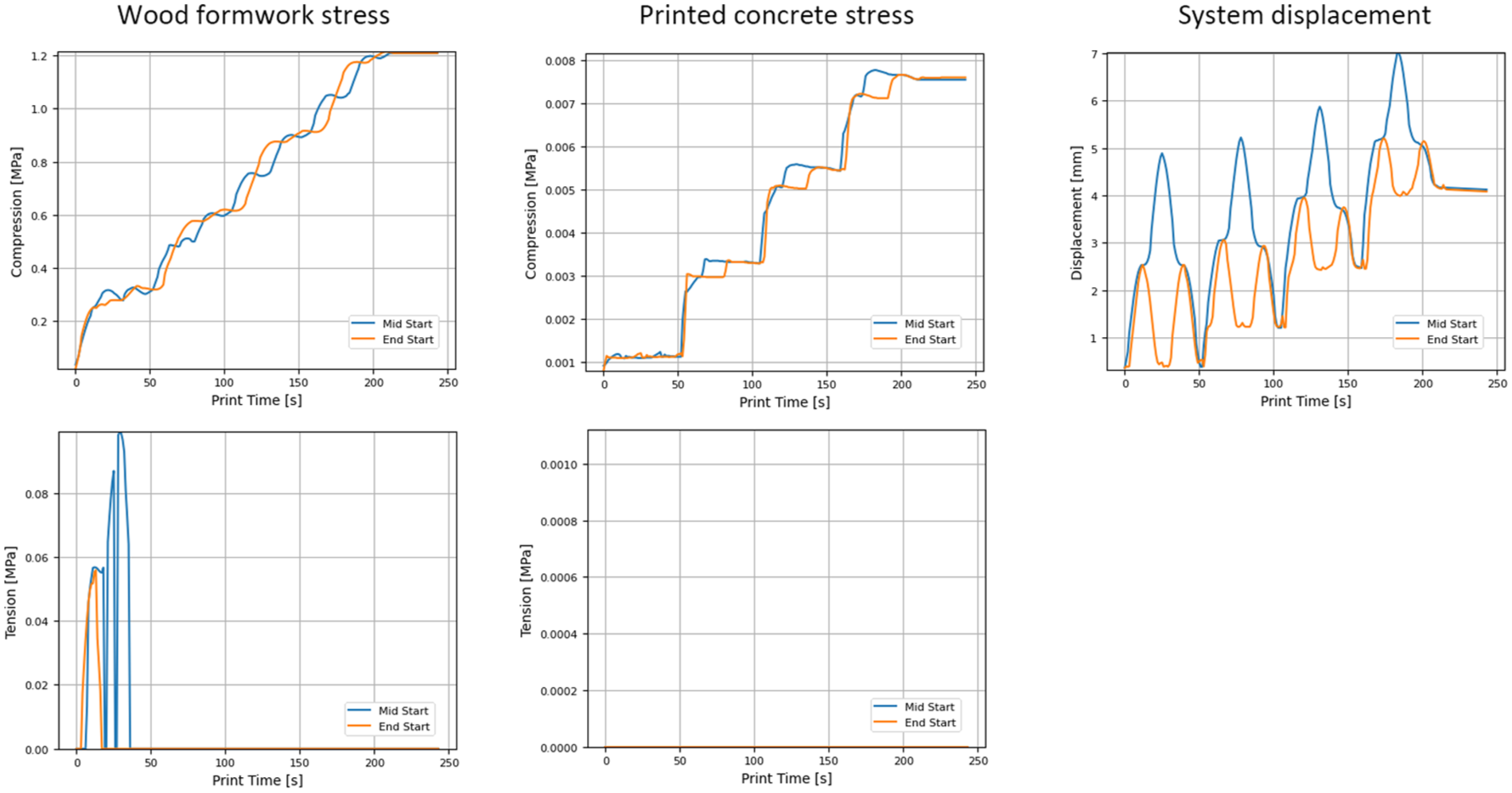
Structural response under different toolpath starting strategies when printing concrete on a wood strip.
Evolution of stress and displacement during printing with different toolpath starting strategies.
Toolpath analysis on a gridshell
The second simulation scenario investigated the more complex case of printing on a doubly curved gridshell supported along its two short edges. Four conformal concrete layers were deposited over the bending-active wood formwork using the same printing speed and layer dimensions as in the strip simulations. Three continuous toolpath strategies were generated using the skeleton-based method: a spiral toolpath, a long-snake toolpath aligned with the longitudinal spanning direction, and a short-snake toolpath oriented in the transverse direction, as shown in Figure 15.
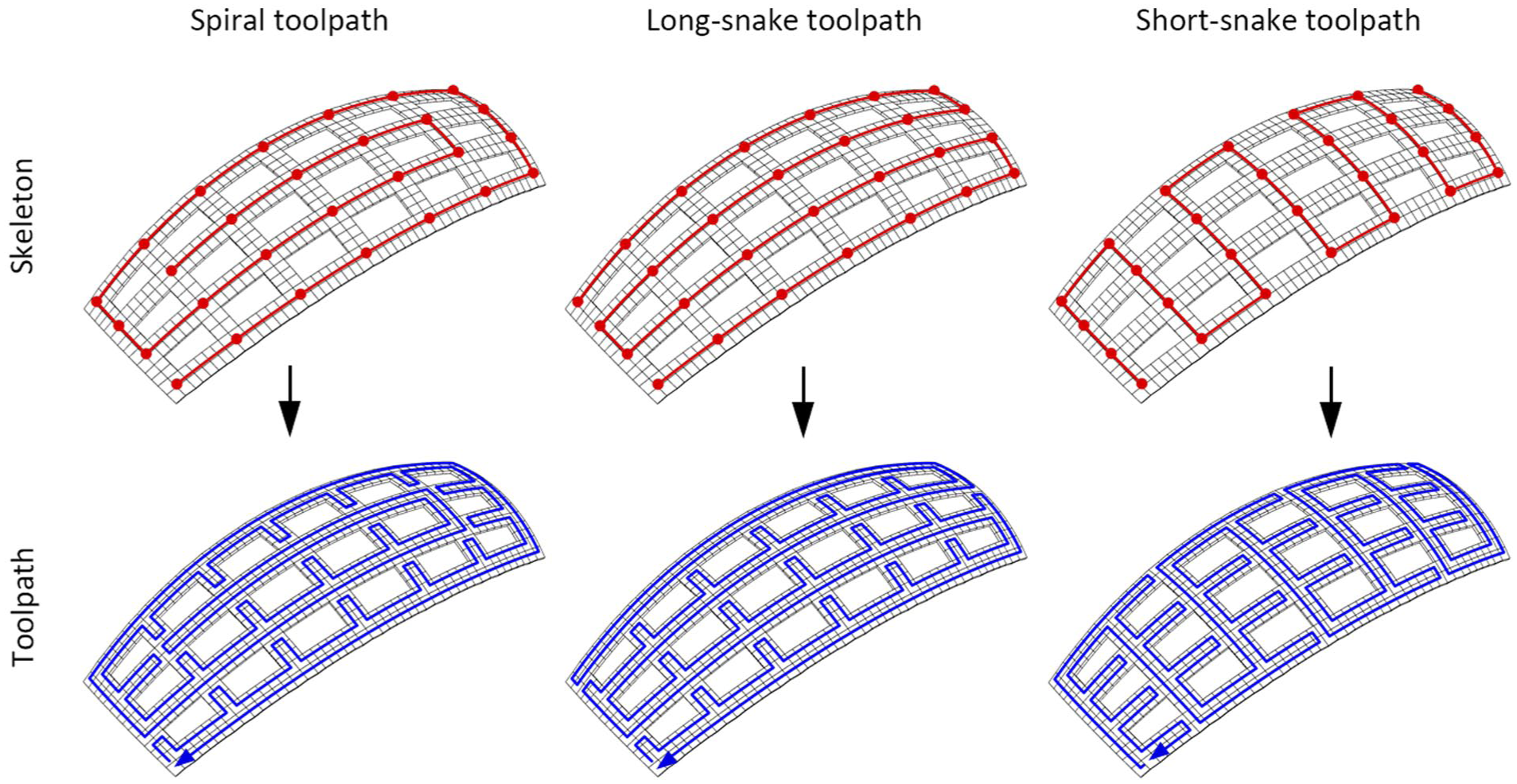
Three continuous toolpath strategies generated from different skeleton graphs: spiral (left), long-snake (center), and short-snake (right).
The simulation results showed marked differences in structural response across the three strategies (Figure 17). In the wood formwork, both compressive and tensile stresses developed with clear fluctuations throughout the printing process. The short-snake path produced the largest amplitude of stress variation, indicating greater dynamic load shifts as material was deposited perpendicular to the main span. The long-snake path resulted in the smallest fluctuations, suggesting a more stable and gradual load increase. The spiral path maintained relatively low tensile stress levels with moderate fluctuations. For the printed concrete, compressive stress increased stepwise as layers were added under all three strategies, but only the short-snake path produced noticeable tensile stress during printing, while the spiral and long-snake paths maintained near-zero tension in the concrete. As shown in the bottom-right part of Figure 16, tensile stress develops in later layers at partially printed intersections due to uneven load distribution under the short-snake toolpath condition. In terms of displacement, the short-snake path resulted in the highest overall values with sudden deformation changes, while the spiral and long-snake paths led to a more gradual and controlled increase.
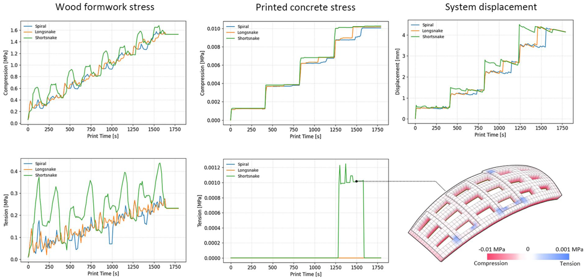
Comparison of structural response under three toolpath strategies: spiral, long-snake, and short-snake.
Influence of interlayer timing
A critical aspect of the printing process is the interplay between concrete curing and layer deposition timing. Concrete begins to cure immediately upon deposition, leading to a gradual increase in material stiffness that influences the structural response as additional layers are added. However, excessive delays between layers risk the formation of cold joints that can weaken interlayer bonding. Previous research has shown that 10 and 30-min intervals between successive layers can produce comparable interlayer bonding quality, while 20-min intervals may lead to reduced bond strength due to differences in surface moisture conditions.23–25
Simulations were conducted for both the strip and gridshell geometries with interlayer intervals of 0, 10, and 30 min. The displacement of the hybrid structure during printing exhibited a clear and consistent trend: deformation decreased as the interlayer interval increased, demonstrating that stiffer, more cured lower layers provided improved support for subsequent material deposition. On the single strip, even a 10-min interval reduced the maximum displacement from 7.0 mm to 5.8 mm for the mid-start toolpath and from 5.2 mm to 3.9 mm for the end-start toolpath. On the gridshell, the spiral toolpath showed maximum displacement decreasing from approximately 4.6 mm with no interval to 3.1 mm at 10 min and 2.1 mm at 30 min, with similar reductions observed for the long-snake and short-snake strategies, as shown in Figure 17. These findings suggest that a short interlayer pause of around 10 min offers a favorable balance between improved structural stability during printing and the preservation of adequate interlayer bonding.
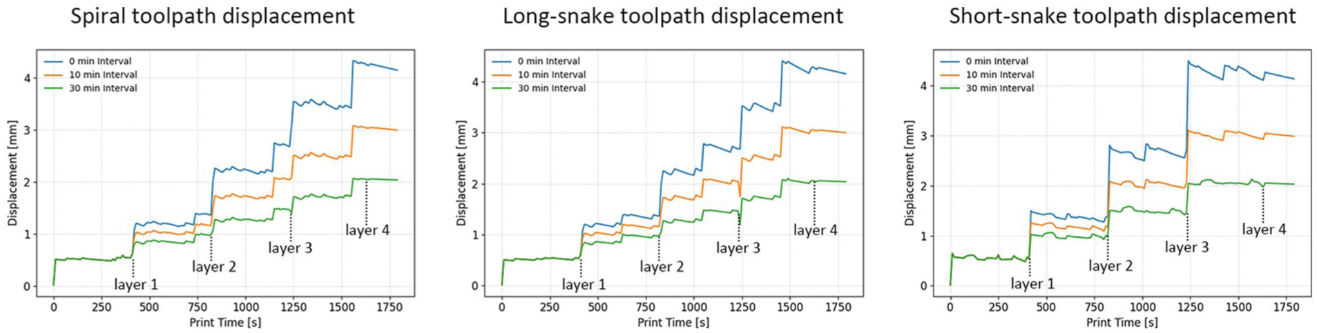
Displacement of the hybrid structure under different toolpath strategies and interlayer time intervals.
Discussion
Synthesis of findings
The experimental and computational investigations converge on several key findings regarding hybrid gridshells produced through conformal 3D printing on bending-active formwork. The physical experiments confirmed feasibility across multiple scales, from material characterization establishing viable timber-concrete composite action, through small-scale validation of the digital workflow encompassing BarkBeetle toolpath generation and sequenced printing, to a full-scale prototype carrying approximately 500 kg of wet concrete before a connection detail failure occurred.
The structural simulations complemented these physical findings by providing quantitative insight into the evolving behavior of the hybrid system during fabrication. The key simulation results can be distilled into practical design recommendations. First, toolpaths should be aligned with the global spanning direction of the structure wherever possible, as span-aligned strategies such as the end-start, spiral, and long-snake paths produce more uniform stress distributions and lower peak displacements compared to transverse strategies such as the short-snake path. Second, the number of longitudinal strips should be even to avoid symmetric load accumulation at a central strip, which the post-experiment analysis showed to be a primary cause of the full-scale prototype failure. Third, a short interlayer pause of approximately 10 min provides meaningful structural benefits during printing without introducing excessive delay that could compromise interlayer bonding. In practice, alternating between long-snake and spiral toolpaths across successive layers can further enhance interlayer bonding by varying the deposition direction and promoting mechanical interlocking.
While the simulations and physical experiments together provide a foundation for practical design guidance, the current framework is best understood as applicable to structures of similar scale and geometric complexity to those investigated here. The full-scale prototype spanning 4.6 meters represents the upper bound of what has been validated to date. Extending the method to longer spans would require revisiting several interacting parameters simultaneously: the number of printed layers increases the cumulative load on the formwork, longer toolpaths extend the time between revisiting any given point on the structure, and higher overall loads amplify the consequences of suboptimal print sequencing or connection detailing. Based on the simulation results, connection capacity at the formwork boundaries is likely to be the governing constraint as span increases, preceding concrete material failure as the critical limit state. Future work should therefore include systematic parametric studies linking span length, strip geometry, layer count, and connection capacity to establish clearer bounds for the application of this construction method.
Relation to prior work and current limitations
This research builds directly upon the hybrid gridshell concept introduced by Schleicher and Herrmann, which demonstrated the potential of bending-active formwork for concrete shell construction using manually applied mortar and CFRP strips. 10 The present work advances that concept in two significant directions: first, by replacing manual concrete application with robotic conformal 3D printing, enabling greater precision, repeatability, and scalability; and second, by transitioning from CFRP to timber formwork, which offers advantages in cost, availability, and environmental impact. The development of the BarkBeetle toolpath generation plugin and the voxel-based simulation framework represent additional contributions that provide the computational infrastructure needed to support this construction method at larger scales.
Several limitations should be acknowledged. The structural simulation employs a linear elastic material model that does not capture cracking, plastic deformation, or interface debonding in early-age concrete. This is a significant constraint for the present system: the thin concrete layers characteristic of conformal deposition on bending-active formwork are inherently susceptible to tensile cracking and brittle failure, and the post-experiment FEM results in Section “Post-experiment structural analysis” already show predicted tensile stresses exceeding the typical tensile capacity of the concrete mix at the scales investigated. A nonlinear damage or plasticity model would be needed to properly assess crack initiation, propagation, and the risk of catastrophic failure in thin overhang applications. The formwork registration process remains time-consuming for complex geometries. The full-scale prototype failure revealed that connection detailing requires substantially more attention, as the bolted connections proved to be the weakest link. The question of what occurs structurally to the partially cured concrete shell if the bending-active formwork were to fail mid-print, as observed in the full-scale experiment, remains an open research question. The physical experiment provides preliminary evidence that partially cured concrete can maintain some geometric integrity after formwork collapse, but the mechanisms of crack initiation and propagation under such a scenario have not been systematically investigated and represent an important direction for future work. Additionally, depositing concrete onto dissimilar substrate materials introduces differential shrinkage and thermal expansion mismatches between the timber formwork and the concrete layer. These effects, which are not captured in the current simulation framework, could contribute to interface cracking and delamination over time, particularly as the concrete transitions from a fresh to a hardened state. Characterizing and mitigating these effects will require targeted experimental investigation. Finally, a quantitative assessment of material efficiency gains relative to conventional construction has not yet been conducted.
Conclusion and outlook
This paper has presented an integrated fabrication and analysis framework for constructing wide-spanning concrete structures by combining bending-active formwork with conformal 3D printing. The methodology was validated through a progressive experimental campaign spanning material characterization, small-scale tests, and a full-scale 4.6 m prototype, complemented by a voxel-based finite element simulation framework that evaluated the influence of toolpath strategies and interlayer timing on structural stability during printing. The principal findings demonstrate that span-aligned toolpaths reduce formwork buckling and promote uniform stress distribution, that even numbers of longitudinal strips prevent problematic central load accumulation, and that short interlayer pauses of approximately 10 min enhance printing stability without significantly compromising interlayer bonding.
The proposed method holds promise for both prefabricated and on-site construction. Modular gridshell elements could be manufactured under controlled factory conditions, while the portable nature of bending-active formwork combined with mobile robotic platforms could enable responsive on-site construction. The methodology also supports the integration of functional elements, as envisioned for a planned technology demonstrator combining structural performance with building envelope functions.
Future research should focus on developing robust connection details, optimizing print sequencing through real-time monitoring, conducting comprehensive structural testing under representative loading, and incorporating advanced material models into the simulation framework. The findings presented here provide a foundation for advancing conformal 3D printing on bending-active formwork toward sustainable, material-efficient construction of curved, long-span architectural elements.
Footnotes
Acknowledgements
The authors thank Print4D for providing access to their robotic fabrication facilities in Prague, and the Department of Architecture at UC Berkeley and the College of Environmental Design (CED) for providing the academic environment that made this research possible. Special thanks are due to Yasaman Yavaribajestani, Todd Zhou, and Lydia Moog for their contributions to the experimental work.
Declaration of conflicting interests
The authors declared no potential conflicts of interest with respect to the research, authorship, and/or publication of this article.
Funding
The authors disclosed receipt of the following financial support for the research, authorship, and/or publication of this article: This research was funded by the Bakar Fellows Program, the Hellman Fellows Fund, the Al-Falah Program in Science and Engineering, and the Kuwait Foundation for the Advancement of Science (KFAS). The authors thank these foundations for their financial and intellectual support.