
Abstract
The mass variances of materials in buckets and the movements of excavation arms greatly impact powertrain vibration transmissibility in hydraulic excavators under working conditions. If the influence of mass variation among bucket contents and excavation arm motions on vibration transmissibility is not considered, then only limited improvements can be made to vibration isolation performance. In this paper, vibration transmissibility suppression for hydraulic excavators operating under working conditions were studied via multi-objective optimization for stiffness coefficients of suspension elements (SEs). First, the rigid-flexible coupling model of a hydraulic excavator with a flexible base was built using ADAMS software. In the model, the stiffness coefficients of the SEs were the targeted variables with constrained conditions, while the multi-objectives for optimization were the vibration transmissibility and energy decoupling rates of the powertrain. Vibration isolation transmissibility (VIT) of the mounting system was compared between situations with non-optimized and optimized stiffness coefficients. Finally, the amplitude changes of the resultant SE support forces were used to illustrate the effects of powertrain vibration transmissibility suppression. We found that the average value of VITs increases significantly during the optimization process for the stiffness coefficients of SEs, which indicates that the mounting system has better vibration isolation performance. The smaller amplitudes of the resultant support force illustrate the improvements to the performance of vibration transmissibility suppression of the powertrain via the optimization process.
Keywords
Introduction
Vibration and noise control is very important for hydraulic excavators in working conditions .1–2 Serious vibrations will dramatically shorten the service life of the powertrain and reduce the working efficiency and reliability of hydraulic excavators. Noise from the excessive vibrations will accelerate the fatigue process of operators for hydraulic excavators in working conditions. The powertrain is one of the main sources of vibrations and noise in excavators and is connected to the base by a mounting system.3–4 The mounting system participates in motion control of powertrain and the collision and interference prevention with other components. More importantly, the mounting system isolates the vibrations from powertrain to the base and cabin of the excavator. Therefore, the design and optimization of suspension elements (SEs) is critical for vibration transmissibility suppression from the powertrain to the cabin of hydraulic excavators.
Optimization of the mounting system is mainly carried out in automobiles to suppress vibration transmissibility based on decoupling theory .5–7 With the rigid body assumption of the powertrain, a 6 degree of freedom (DOF) model is often used and each SEs is modeled as a set of three tri-axial spring elements. Their stiffness coefficients are designated as targeted variables. The aims are to restrict the natural frequencies of a powertrain to prescribed ranges, and to maximize the mode energies in each decoupling coordinate. Typically, research in this field involves analytical methods for decoupling automotive powertrains, such as those used by Singh et al. .8–10 However, the improvements on the energy decoupling rates of the mounting system do not indicate that the powertrain’s vibration transmissibility is suppressed at the same time. Minimization of transmitted forces from the engine to the base is another important target. Ashrafiuon et al. 11–12 carried out the optimization of an aircraft engine mount, while Swanson et al. 13 developed an optimization method for engineering applications. Hafidi et al. 14 determined the optimal positions of engine mounts by using decoupling theories and minimized transmitted forces.
Until now, few reports have focused on vibration transmissibility suppression of powertrains in hydraulic excavators via optimization of the mounting system .15–16 It should be noted that the base of hydraulic excavators has a considerable mass and experiences significant elastic deformation, which greatly influences the vibration transmissibility of the powertrain .17–18 Moreover, the mass variances among bucket contents and the movements of the excavation arms also affect the vibration transmissibility characteristics of the powertrain. Neglecting these factors will lead to underestimation or misestimation of the effects of vibration transmissibility suppression from the powertrain. Our previous work 15 does not consider the influence of mass variation among bucket contents and motion of the excavation arm in working conditions on vibration isolation performance of hydraulic excavators. In this paper, vibration transmissibility suppression from the powertrain is further investigated for hydraulic excavators in working conditions by optimization of stiffness coefficients for SEs. A rigid-flexible coupling model of a hydraulic excavator based on the finite element method (FEM) was built using ADAMS software. The energy decoupling rates and vibration transmissibility were used for multi-objective optimization, while the variables were set as the stiffness coefficients of SEs. With the given constrained conditions, the multi-objective optimization was solved by the NSGA-II algorithm . 19 Vibration isolation transmissibility (VIT) of the mounting system based on the rigid-flexible coupling model was compared for non-optimized and optimized stiffness coefficients, while the resultant support forces of the mounting system are shown to illustrate the effects of optimization process.
The rigid-flexible coupling modeling of hydraulic excavators in working conditions
The rigid-flexible coupling model of hydraulic excavators
The model for simulations by ADAMS was a rigid-flexible coupling model, where the powertrain and base were viewed as the rigid and flexible bodies, respectively. The dynamic modeling for the powertrain with a mounting system was established using the well-known commercial software Solidworks and ADAMS. After a simplified procedure for the complex structures, the powertrain model was built in Solidworks and its FEM model was generated by ADAMS using the Parosolid type of three-dimensional model in Solidworks. The SEs were simulated by bushing forces and Maker points by neglecting their mass (relative to the mass of the powertrain). The FEM model for simulations of dynamics of the powertrain with four SEs is shown in Figure 1. The parameters used for the powertrain and the inertial coordinates can be found in Ref.
15
. The natural frequencies of the powertrain were compared based on numerical calculations and the simulations with the ADAMS model ,
15
which confirmed the reliability of the ADAMS model of the powertrain mounting system. The ADAMS model of powertrain with the mounting system.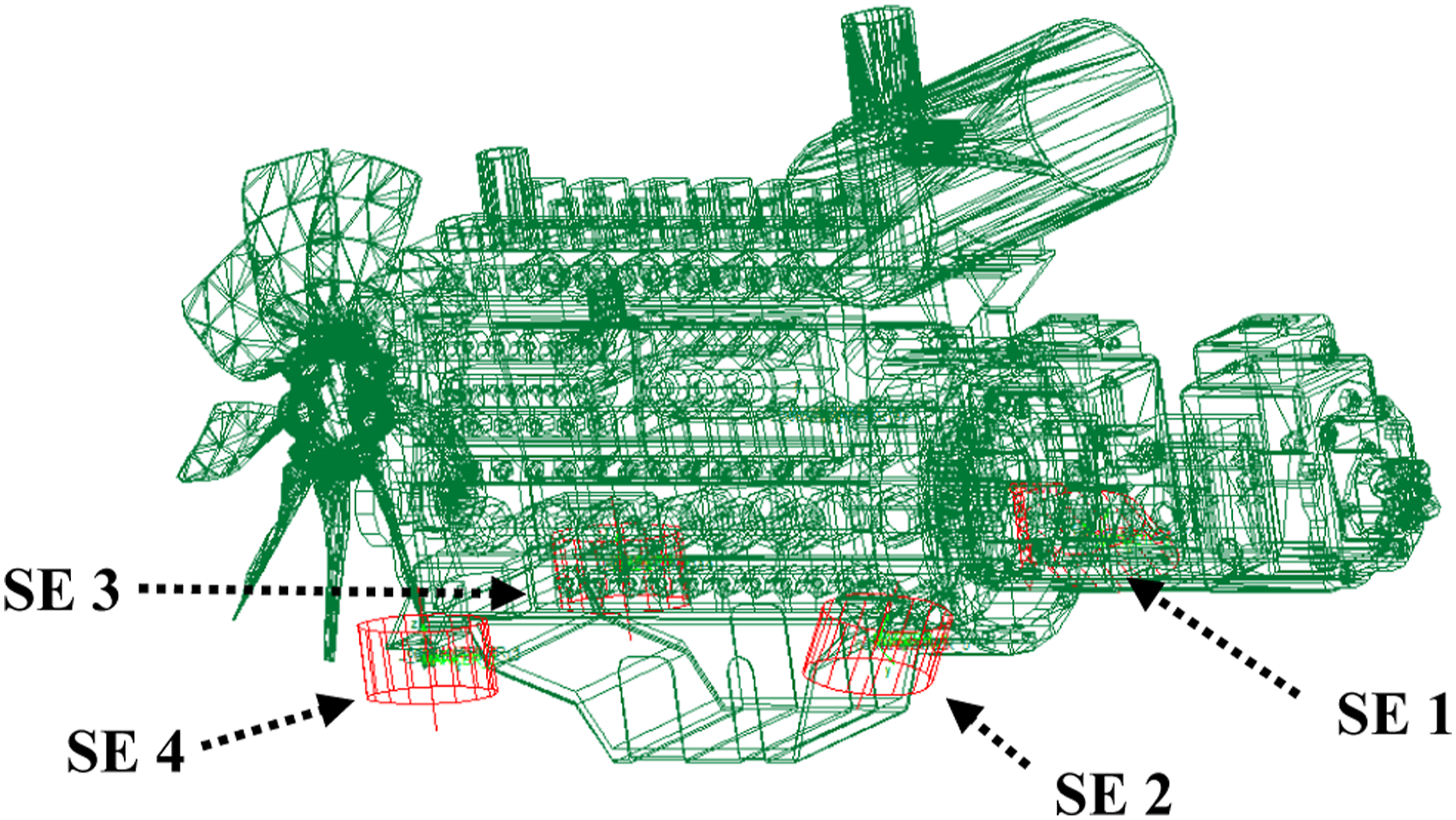
The simplified complex structures and the powertrain were assembled in the 3D model of the hydraulic excavator (Figure 2). In the rigid-flexible coupling model (Figure 1), the base was defined as a flexible body. However, the software ADAMS has restrictions on the flexibility of complex components. The software ANSYS was therefore employed to increase the flexibility of the base. An MNF file generated with ANSYS was exported and substituted the rigid area in the ADAMS model to obtain a compliant base. The details for flexibility in ANSYS can be found in the illustrations of the software .
15
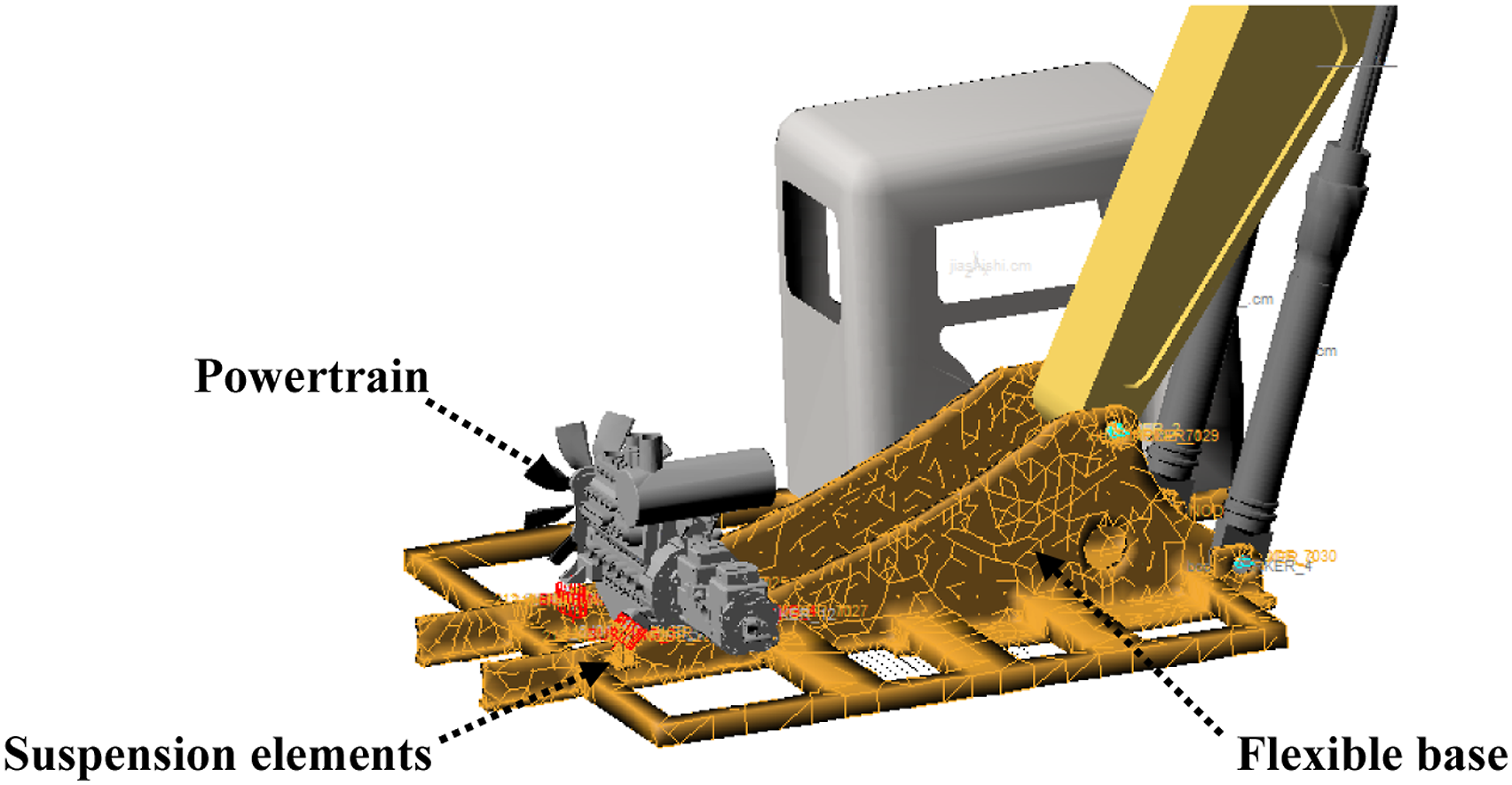
The ADAMS model of the powertrain and the mounting system were integrated with the flexible base, and the same coordinate system was used to establish the rigid-flexible coupling model for the hydraulic excavator with substituting the rigid base with an MNF file from ANSYS (Figure 3). The 3D model of a hydraulic excavator in working conditions. The flexible base of the rigid-flexible coupling model.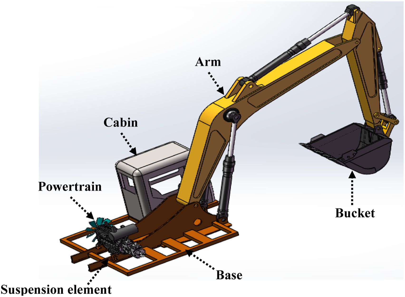
The working conditions for simulations of the rigid-flexible coupling model to explore the mounting system’s vibration transmissibility were set as a loading, gyration, and discharging procedure. The forces from the moving arm and hydraulic cylinders in the bucket are usually neglected in the working conditions of hydraulic excavators. Here, we considered these forces. The volume of bucket was set to 1.1 m3. If the density of the soils in the bucket is set to 180 kg/m2, then the gravity from the soils in the bucket is 19.4 KN. According to the period of this working condition, the function STEP in ADAMS was used to simulate the operating condition, and was implemented as follows: (1) STEP function for the gravity from the soils in the bucket STEP (TIME, 2, 0, 7.5, 19,400)+ STEP (TIME, 10.5, 0, 12.5, −19,400) (2) STEP function for gyrations of hydraulic excavators STEP (TIME, 7.5, 0, 10.5, 90d)+ STEP (TIME, 12.5, 0, 15, −90d)
Validation of the rigid-flexible coupling model
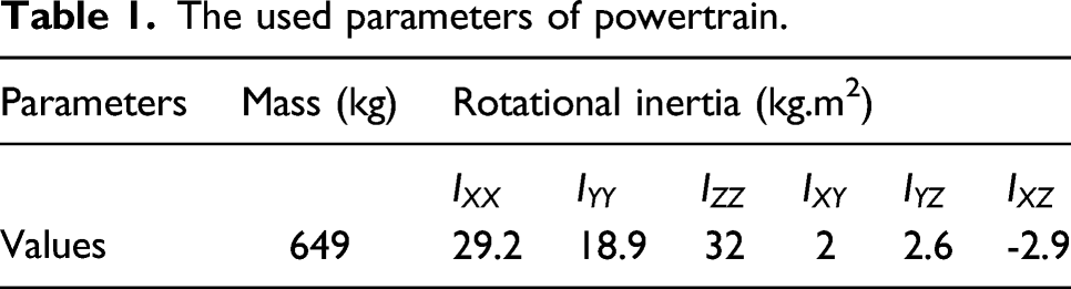
With the assumptions of small motions, the powertrain in Figure 1 was modeled as a rigid body with a time-invariant inertia matrix of dimension 6. As shown in Figure 4, the inertial coordinate system The inertial coordinate system 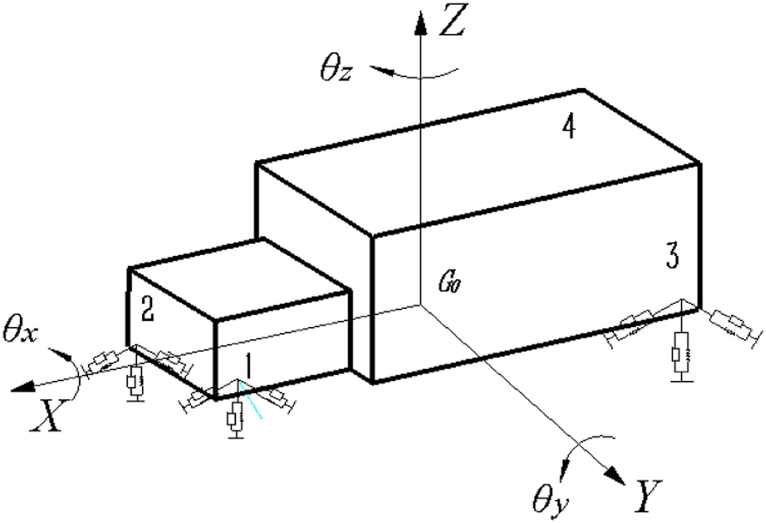
The used parameters of powertrain.
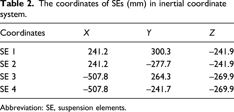
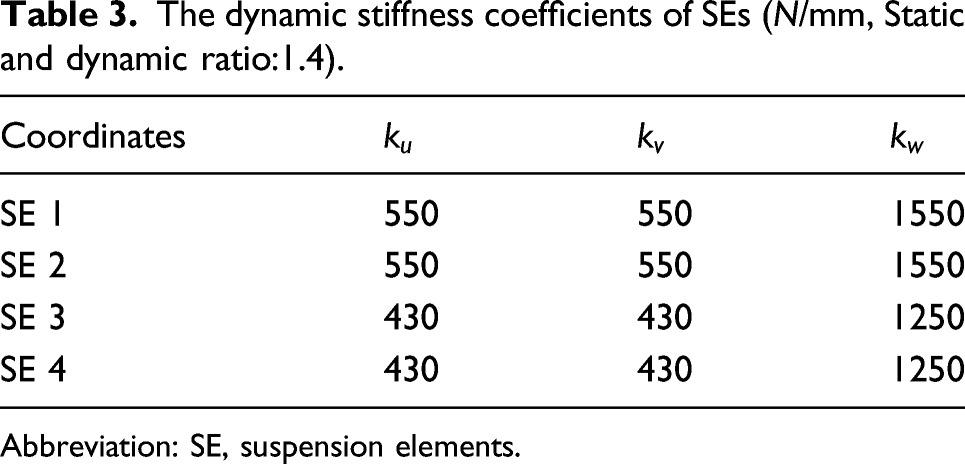
The dynamic model of SEs in Figure 3 included three tri-axial spring elements, which are specified with local coordinates The local coordinate system The coordinates of SEs (mm) in inertial coordinate system. Abbreviation: SE, suspension elements. The dynamic stiffness coefficients of SEs (N/mm, Static and dynamic ratio:1.4). Abbreviation: SE, suspension elements.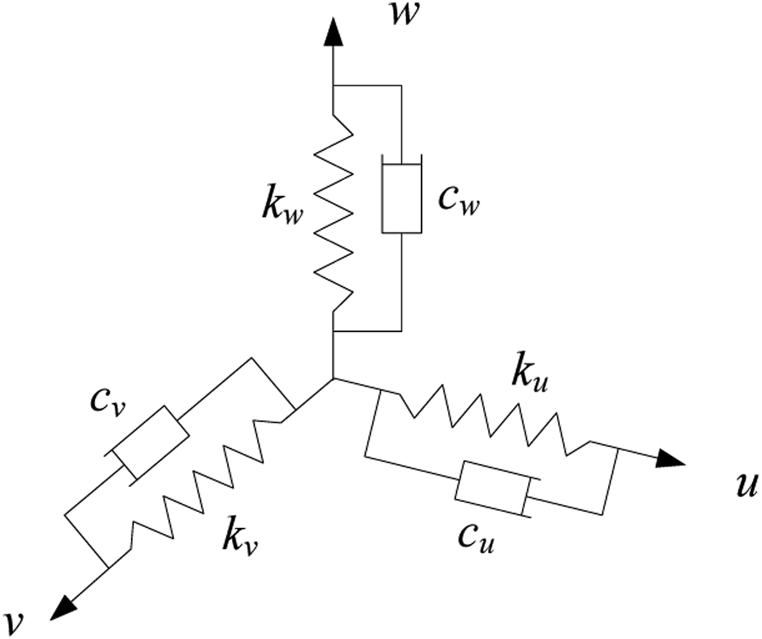
The inertial coordinate system 
Based on 
Then, the kinetic energy on the 
The 6 DOF model (1) is commonly used for analysis of dynamic responses of the powertrain with the established coordinate systems in Figures 3 and 4. The natural frequencies and energy decoupling rates can be calculated based on the 6 DOF model with the same parameters by MATLAB. Free vibration analysis of the rigid-flexible coupling model was conducted, and the natural frequencies and energy decoupling rates were obtained to verify the effectiveness of the model. The results were compared with that of the 6 DOF model, which are shown in Tables 1 and 2, respectively.
Comparisons of the natural frequencies with six DOF model.
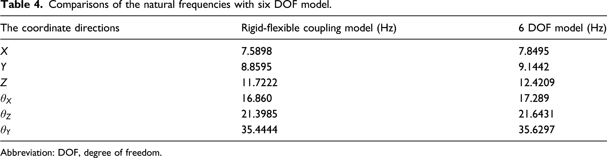
Abbreviation: DOF, degree of freedom.
Comparisons of the energy decoupling rate with six DOF model.
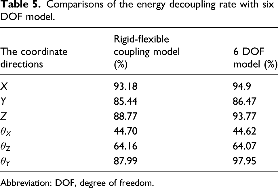
Abbreviation: DOF, degree of freedom.
The multi-objective optimization for stiffness coefficients of SEs
In recent years, the design and optimization of the mounting system in automobiles and other machines have been mainly based on the energy decoupling theory ,7–9 which are intended to obtain higher energy decoupling rates on each generalized coordinate. However, the vibration transmissibility of the mounting system is independent of its energy decoupling rates on each generalized coordinate. The improvements on the energy decoupling rates of the mounting system do not indicate that the powertrain’s vibration transmissibility is suppressed at the same time. Therefore, a multi-objective model simultaneously considering the energy decoupling rates and vibration transmissibility was used for the optimization of stiffness coefficients for SEs.
The objective functions
The maximum energy decoupling rate on the six coordinates of the mounting system was assigned as the first objective function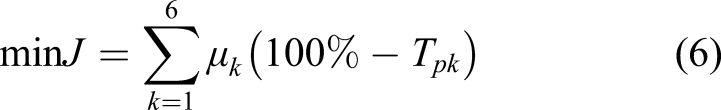
The 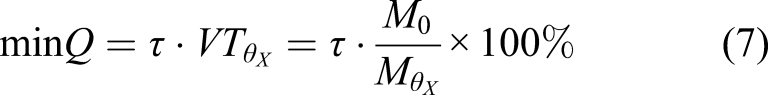
The designed variables and constraint conditions
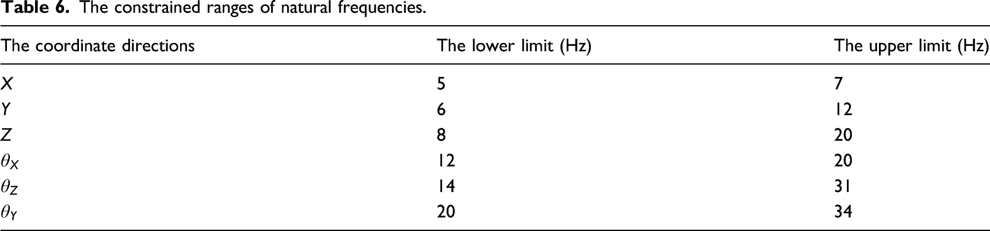
The designed variables for multi-objective optimization were defined as the dynamic stiffness coefficients of SEs. According to the dynamic model of a mounting element in Figure 4, the corresponding stiffness coefficients were 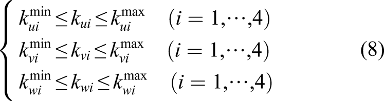

The constrained ranges of natural frequencies.
The optimization algorithm
The parameters of NSGA-II algorithm.

The working procedure of the NSGA-II algorithm has been described previously, so a brief description of the NSGA-II algorithm as used in this paper is presented. (1) Generate an initial population with suitable size. (2) Create an offspring population using binary tournament selection based on crowding-comparison operator, crossover and mutation performed on the parent population. The offspring population and its parent population are combined to produce the entire population. (3) Perform a fast non-dominated sorting approach on the entire population to identify different non-dominated fronts of objective functions. (4) Create a new parent population with the same size from the obtained fronts. (5) Repeat the process until the maximum number of iterations is reached.
For more details on the procedure for NSGA-II algorithm-based optimization, readers are encouraged to refer to the original paper . 19
Vibration transmissibility suppression with the optimized stiffness coefficients
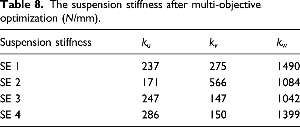
The results of the optimization procedure
The suspension stiffness after multi-objective optimization (N/mm).
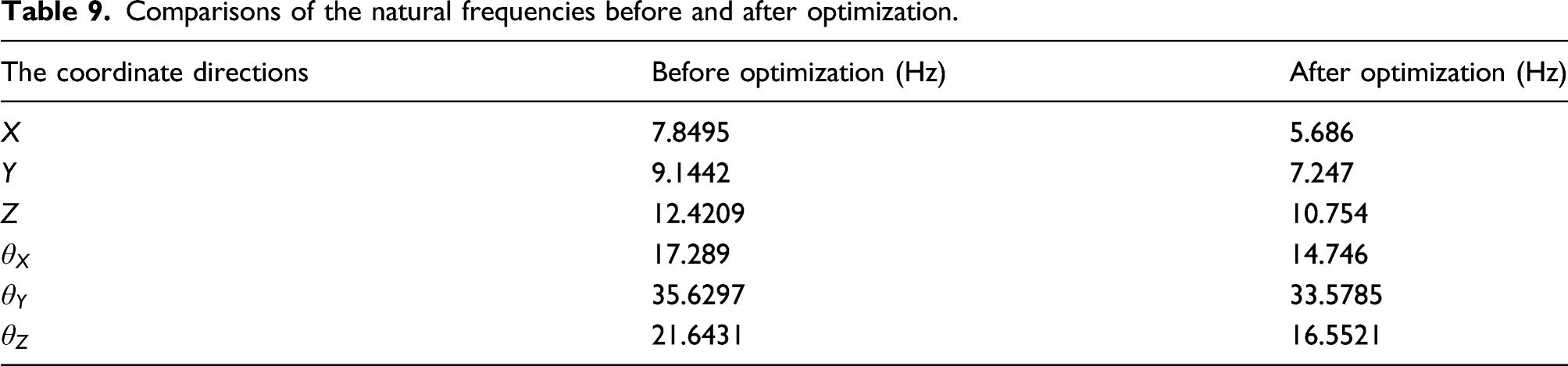
Comparisons of the natural frequencies before and after optimization.
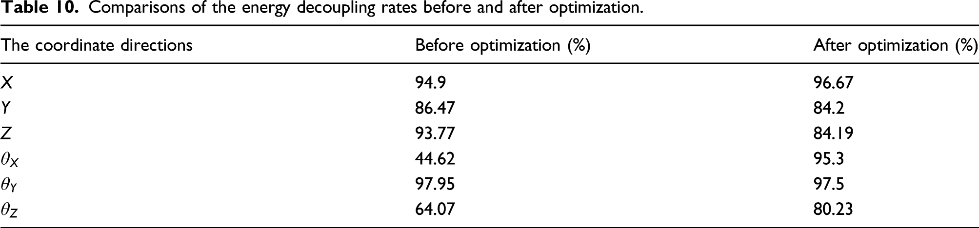
Comparisons of the energy decoupling rates before and after optimization.
Next, in order to investigate the changes of vibration isolation performance and the vibration transmissibility of the mounting system, the VIT and the resultant support forces were compared.
Vibration transmissibility suppression analysis of the mounting system
In engineering measurements, the VIT has different definitions with vibration transmissibility in equation (7) and is often used to evaluate the vibration isolation performance of mounting systems in automobiles. The fundamental idea of VIT is defined as the ratio of the response amplitudes of the isolated body and the base. For vibration transmissibility isolation from the powertrain in hydraulic excavators, the VIT is the ratio of the vibration response amplitudes of the powertrain and the base, which cannot be calculated by simulations of the powertrain only. Traditionally, the VIT is obtained based on vibration responses from experimental measurements. With better precision in vibration measurements, acceleration signals of the driving and driven parts are collected to compute the VIT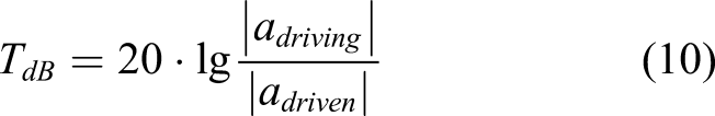
To compute the VITs of the powertrain, the vertical vibration accelerations of the powertrain and base were collected from the simulations based on the rigid-flexible coupling model with the non-optimized and optimized stiffness coefficients of SEs. It remains stable during the parking condition and generates fluctuations in the gyration of the arm. This can be explained by the fact that the inertia force provides shocks to the vertical vibration accelerations of the powertrain. The results of VITs for the rigid-flexible coupling model with the non-optimized and optimized stiffness coefficients of SEs are compared in Figure 6. VITs for the hydraulic excavator with the non-optimized and optimized stiffness coefficients are all larger than 20 dB, and therefore satisfy the requirements of vibration isolation performance for engineering applications. Particularly, the average value of VITs for the hydraulic excavator with the optimized stiffness coefficients is greater than that with non-optimized coefficients. The larger value of VIT indicates better vibration isolation performance of the mounting system, which is improved after the optimization process for the stiffness coefficients of SEs. The vertical VITs of the SEs under the working conditions. Note: SE: suspension elements. VIT: Vibration isolation transmissibility.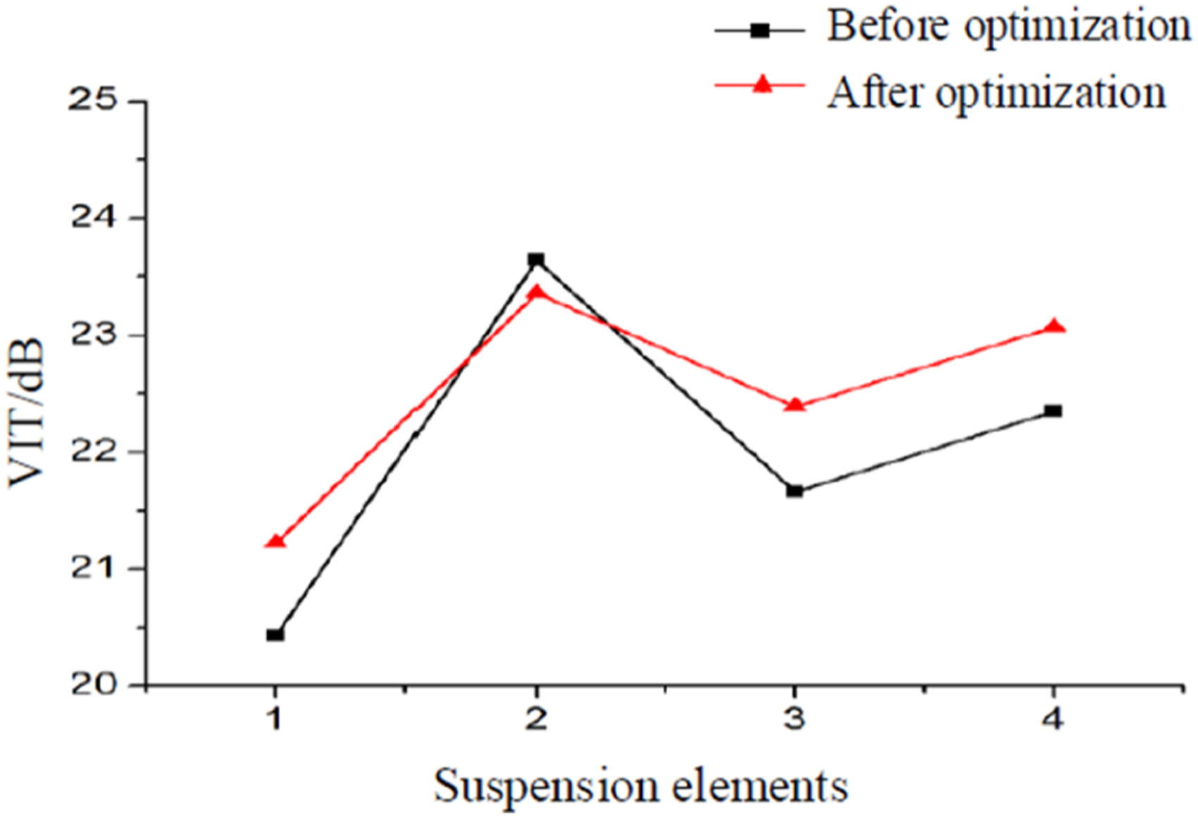
Torque will transfer to the base of hydraulic excavators by SEs from the powertrain. The resultant vertical force of the mounting system also causes fluctuations in the gyration of the arm because of the shock from the inertia force to the powertrain. The resultant support force of the SEs is often chosen to be a critical index to assess the vibration isolation performance .
20
It has larger amplitudes upon starting of the engine and fluctuates with smaller amplitudes at steady state of the engine. To investigate the vibration transmissibility suppression of the mounting system with the optimization process, the support forces of SEs were calculated (Figure 7). Our approach successfully simulated the true situation of the hydraulic excavator under working conditions. The resultant support force of the SEs under working conditions. Note: SE: suspension elements.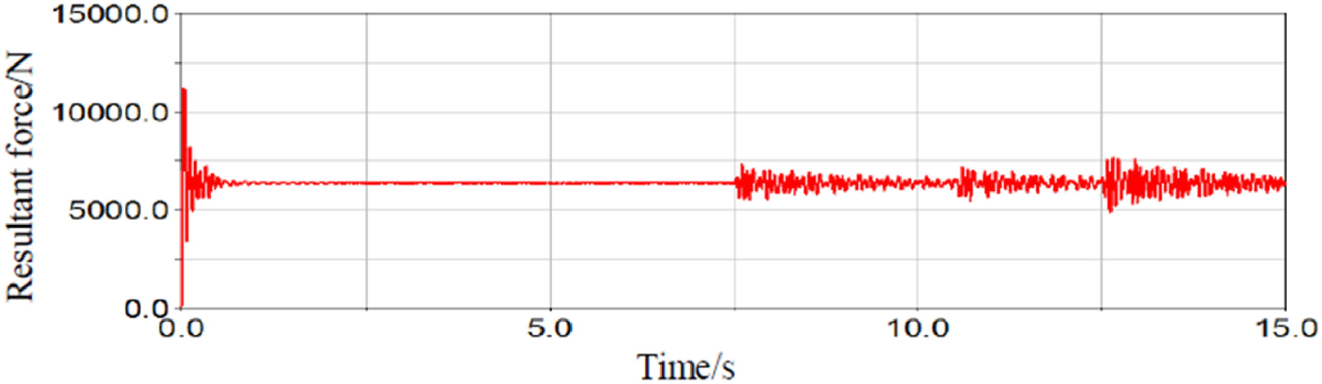
The resultant support force of the SEs reflects the properties of the mounting system on vibration transmissibility suppression. The smaller amplitudes of the force indicate that the mounting system has a better capacity to suppress the vibration transmissibility from the powertrain. Specifically, the fluctuations in the resultant support force in Figure 7 were investigated carefully to analyze the vibration transmissibility suppression with the optimization procedure. Figure 8 shows the comparison of the amplitudes of resultant support forces between the non-optimized and optimized stiffness coefficients. The amplitudes of the resultant forces decrease after the optimization process. These results illustrate that the performance of vibration transmissibility suppression of the powertrain was improved via the optimization procedure of stiffness coefficients. The resultant support force of the SEs before and after optimization under the working conditions. Note: SE: suspension elements.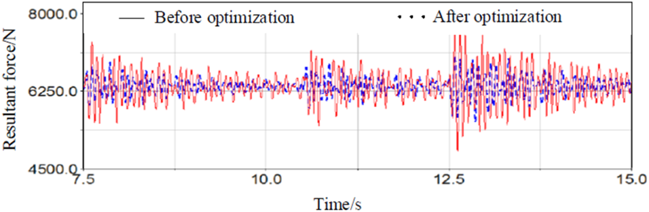
In the process of optimization under working conditions, the influence of mass variation among bucket contents and motions of the excavation arm on the vibration transmissibility characteristics of the powertrain in hydraulic excavators should be considered. If these factors are neglected, the effects of the vibration isolation performance will be underestimated or misestimated. The vertical VITs of the SE in the rigid-flexible coupling model with the optimized stiffness coefficients are all larger than 20 dB, which indicate that the vibration isolation performance with the optimized mounting system is satisfactory. However, if the mass variances of bucket contents and the movements of the excavation arms are not considered in the optimization process, this satisfactory vibration isolation performance may require more adaptability for various working conditions. According to this situation, more restriction conditions are needed to describe the working conditions, and a more complex optimization process must be employed to obtain more suitable stiffness coefficients. However, the computation power required for such an approach is an obstacle to its routine application in engineering. In conclusion, the optimization of the mounting system can improve the vibration isolation performance in hydraulic excavators, while excessive variables and constrained conditions make the process of obtaining the solutions of the optimization problem more difficult.
Conclusions
In this paper, vibration transmissibility suppression for hydraulic excavators in working conditions was studied via multi-objective optimization for stiffness coefficients SEs. First, a rigid-flexible coupling model of a hydraulic excavator with a flexible base was built using ADAMS. The multi-objectives for the optimization were the vibration transmissibility and energy decoupling rates of powertrain, and the stiffness coefficients of SEs were the targeted variables. VITs of the mounting system were compared for simulations with non-optimized and optimized stiffness coefficients. We found that the mounting system had better vibration isolation performance based on the change in VIT values. The smaller amplitudes of the resultant support force illustrate the improvements on the performance of vibration transmissibility suppression of the powertrain via the optimization process.
Footnotes
Declaration of conflicting interests
The author(s) declared no potential conflicts of interest with respect to the research, authorship, and/or publication of this article.
Funding
The author(s) disclosed receipt of the following financial support for the research, authorship, and/or publication of this article: This work was supported by Projects in key fields of colleges and universities in Guangdong (grant no. 2021ZDZX1057) and Guang Dong Basic and Applied Basic Research Foundation (grant nos. 2021A1515010712, 2020B1515120006).