Abstract
In this paper, the flutter analysis is studied for a cylindrical sandwich shell subjected to external supersonic fluid flow. The sandwich shell consists of a re-entrant auxetic honeycomb (AH) core made of functionally graded materials (FGMs) which is covered with two polymeric face layers enriched with either carbon nanotubes (CNTs), graphene nanoplatelets (GNPs), or graphene oxide powders (GOPs). The volume fraction (percentage) of the ceramic phase in the functionally graded auxetic honeycomb (FGAH) core varies from zero at the inner surface to one at the outer one based on either power-law function (P-FGM), exponential function (E-FGM), or sigmoid function (S-FGM). It is assumed that the nanofillers are distributed uniformly inside the face layers. The first-order shear deformation theory (FSDT) and the piston theory are employed to provide the mathematical models of the shell and the aerodynamic pressure, respectively. The governing equations and boundary conditions are derived via Hamilton’s principle. An exact solution is performed in the circumferential direction via harmonic trigonometric functions (sine and cosine) and an approximate solution is performed in the axial direction utilizing the differential quadrature method (DQM). The natural frequencies and corresponding damping ratios are attained through the presented semi-analytical solution and the impacts of several factors on the natural frequencies and the critical aerodynamic pressure of the shell are examined. These factors the type of the FGM, the material index, and inclined angle of the cells in the FGAH core, the thickness of the FGAH core, the type and mass fraction of the nanofillers in the nanocomposite face layers, and boundary conditions.
Keywords
Introduction
Structures with low density are the best options to be used as the core in a three-layered sandwich structure. Since the core of a sandwich structure is not subjected to intense bending stress, it does not need to have high stiffness and strength. Honeycombs are low-weight structures that can be used as a core to achieve a sandwich structure with a high value of stiffness-to-mass ratio. Therefore, honeycomb structures have been utilized in several engineering applications such as mechanical, aerospace, and civil engineering.
There is a fair amount of work associated with the mechanical behaviors of sandwich shells and plates with honeycomb cores. As the most well-known type of honeycomb structures, the hexagonal ones have been extensively used in various engineering fields.1–4 The elastic constants and density of hexagonal honeycomb structures and their influences on the mechanical behavior of structures have been fairly explored in recent decades. In a hexagonal honeycomb structure, the Poisson’s ratios are positive values. However, there are other kinds of honeycomb structures whose Poisson’s ratios can be zero or even negative values. These types of honeycomb structures are called auxetic honeycomb (AH) structures. In comparison with traditional materials and artificial structures, auxetic structures have superior mechanical characteristics such as high fracture toughness, significant shear resistance, high energy absorption, and remarkable indentation resistance. 5 There is a fair amount of work associated with providing relations to estimate the density and elastic constants of various types of AH structures.6–9 Such relations were provided by other researchers to investigate the mechanical analysis (buckling, bending, vibration, aeroelastic stability, etc.) of sandwich structures with AH cores. Duc et al. 10 inspected the vibration analysis of a doubly-curved sandwich panel with an AH core. They examined the effects of geometric factors of the AH core on the natural frequencies and dynamic response to a blast load. The forced vibrational analysis of a cylindrical sandwich shell with an AH core subjected to moving pressure was inspected with Eipakchi and Naserkani. 11 They inspected the dependency of the critical frequency, dynamic response of the shell, and critical velocity of the moving pressure on the geometric factors of the AH core. Nguyen et al. 12 inspected the free vibration and dynamic buckling behaviors of a sandwich plate with an AH core covered with two GNP-reinforced polymeric face layers. They focused on the impacts of the geometric factors of the AH core on the natural frequencies and stability regions of such a sandwich plate. The buckling analysis of a sandwich plate with an AH core covered with laminated composite layers was inspected by Xiao et al. 13 They provided a parametric examination to study the impacts of the geometric factors of the AH core on the critical buckling load of such a sandwich plate. Xu et al. 14 studied the free in-plane vibration analysis of an AH structure with curved sinusoidal walls. They investigated the optimization of such an AH structure and focused on the influences of using it on the amplitude of vibration and energy absorption capacity of such an AH structure.
An exact solution was presented by Cong and Duc 15 on the nonlinear dynamic analysis of a stiffened porous doubly-curved sandwich panel with an AH core subjected to mechanical, thermal, and blast loadings. They inspected the impacts of geometric factors of the AH core on the nonlinear dynamic deflection of such a sandwich panel. In another work, they studied the nonlinear thermo-mechanical buckling and post-buckling analyses of a stiffened sandwich doubly-curved panel with an AH core. 16 In this work, they supposed that the shell is under axial load, external pressure, and temperature rise and studied the impacts of geometric factors of the AH core on the thermo-mechanical stability regions of such a sandwich shell. The natural frequencies of a sandwich plate with an AH core covered with two metal-ceramic FG face layers were estimated by Pham et al. 17 The dependency of the natural frequencies of the plate on the geometric factors of the AH core was inspected by them. Cong et al. 18 presented a parametric examination for the nonlinear vibration analysis of a doubly-curved sandwich panel with an AH core and CNT-reinforced face layers. They incorporated the temperature-dependency of the material properties of the materials and investigated the effects of geometric factors of the AH core on the nonlinear dynamic response and natural frequencies of such a sandwich shell. The nonlinear vibration analysis of a sandwich plate with an AH core and two piezoelectric face layers was studied by Quan et al. 19 They inspected the influences of the geometric factors of the AH core on the dynamic deflection and natural frequencies of such a sandwich plate. Dat et al. 20 inspected the nonlinear vibrational behavior of a sandwich plate with an AH core covered with two magneto-electro-elastic face layers. They assumed that the plate was under a blast load and studied the impacts of geometric factors of the AH core on the dynamic response and natural frequencies of such a sandwich plate. Pakrooyan et al. 21 examined the free vibrational behavior of a sandwich plate with an AH core utilized as the wall of a fluid-filled tank. They inspected the effects of the AH core on the natural frequencies of the fluid-filled tank. The buckling analysis of a stiffened truncated conical sandwich shell with an AH core surrounded by a foundation was examined by Duc et al. 22 They examined the influences of geometric factors of the AH core on the critical buckling load of such a sandwich shell. The free vibration and thermal buckling analyses of a viscoelastic doubly-curved sandwich shell with a tunable AH core and FGM face layers were investigated by Li and Liu. 23 They studied the influences of the geometric factors of the tunable AH core on the critical temperature rise and the natural frequencies of such a sandwich shell.
Sarafraz et al.24,25 inspected the mechanical free vibration, buckling, and flutter behaviors of a sandwich plate with an AH core and two three-phase polymeric layers enriched with GNPs and glass fibers. They presented a parametric examination to study the impacts of the mass fraction of the GNPs and fibers and the geometric parameters of the AH core on the natural frequencies, critical buckling load, and flutter boundaries of such a sandwich plate. The chaotic dynamic characteristics of a cylindrical sandwich panel with an AH core subjected to thermal loading were studied by Ha et al. 26 They inspected the impacts of geometric factors of the AH core on the chaotic characteristics of such a sandwich panel. Liu et al. 27 investigated the static bending analysis of a sandwich plate with a tunable AH core covered with two metal-ceramic FG layers. They inspected the impacts of the geometric factors of the AH core on the deformation and stress distribution in such a sandwich plate. The crashworthiness of hexachiral AH structures subjected to an in-plane load was studied by Sadikbasha and Pandurangan. 28 They focused on the crashworthiness and energy absorption capacity of sandwich structures with such a core. Necemer et al. 29 used the ANSYS software and inspected the fatigue resistance of several AH structures made of aluminum. They investigated five different types of AH structures including S-shaped, chiral, star-shaped, double arrowhead, and re-entrant types. Yu et al. 30 examined the failure analysis of an AH structure under compressive loading. They reported some useful results via the ABAQUS software and compared their results with the experimental ones to confirm the precision of their model. Rai et al. 31 inspected the dynamic response of a sandwich panel with an AH core subjected to an explosive load. They presented a parametric examination to optimize the energy absorption capacity of such a sandwich panel.
Since most of the bending loads are endured by the face layers of a sandwich structure, it is essential to utilize thin face layers fabricated from materials of high stiffness and strength. One of the best choices is nanocomposites which includes a polymeric matrix enriched with various types of nanofillers such as either CNTs,32–36 GNPs,37–40 or GOPs.41,42 Due to the strong interatomic bonds between the carbon atoms, such nanofillers benefit from extremely high elastic moduli. Meanwhile, they benefit from significantly low density. As a result, CNTs, GNPs, and GOPs have high stiffness-to-mass ratios and can be used as reinforcing nanofibers to fabricate nanocomposites with extraordinary mechanical characteristics. Thus, these nanofillers have been extensively utilized as reinforcements in composite structures in various engineering fields such as aerospace, mechanical, and civil engineering fields.
It was in the middle of the 1980s when the concept of metal-ceramic FGM was introduced by some materials scientists in Japan. 43 FGMs are usually fabricated from the composition of two materials including ceramic phase and metal phase whose volume fractions vary continuously in one, two, or three directions. The most important advantage of FGMs is their good capacity to endure simultaneous thermal and mechanical loadings. Consequently, these types of non-homogenous materials have been utilized in several engineering applications such as aerospace, civil, and mechanical engineering. As a new idea to attain an extremely low-weight structure which benefits from high endurance against thermo-mechanical loading, some researchers have proposed to fabricate AH structures from FGMs. The authors’ best knowledge shows that there are a few numbers of works that examine the influences of utilizing FGAH cores on the mechanical behaviors of structures.44–46 However, most of them are associated with the vibration analysis of sandwich plates with FGAH cores. Yet, there is no work regarding the effects of utilizing FGAH cores on the aeroelastic stability analyses of shell structures. Since aerospace structures are exposed to simultaneous intense mechanical and thermal loads and are supposed to have a high stiffness-to-mass ratio, honeycomb structures and FGMs have wide usage in the fabrication of aerospace structures. To provide necessary data for future aerospace structures, the present work is dedicated to the supersonic flutter analysis of a cylindrical sandwich shell with a re-entrant FGAH core covered with two polymeric face layers enriched with either CNTs, GNPs, or GOPs. This work is the first theoretical research regarding the aeroelastic stability of a sandwich shell with an FGAH core and nanocomposite face layers. The effects of several factors on the aeroelastic stability of the shell are studied such as type of the FGM, material index, and the inclined angle of the cells in the FGAH core, the thickness of the FGAH core, type and mass fraction of the nanofillers in the nanocomposite face layers, and boundary conditions. The results of the presented work can be utilized in the design, analysis, and optimization of aerospace structures.
Mathematical modeling
Material properties
As Figure 1 shows, a cylindrical sandwich shell of mean radius R, length L, and thickness h exposed to supersonic fluid flow of density ρ∞ and velocity U∞ is considered. The shell consists of a re-entrant FGAH core of thickness h
2
= h
c
covered with two polymeric face layers of the same thickness h
1
= h
3
= h
f
= 0.5 (h-h
c
) which are enriched with either rectangular-shaped GNPs, cylindrical-shaped CNTs, or circular-shaped GOPs. As Figure 1 shows, it is assumed that the fluid flows parallel to the axial direction of the shell. A cylindrical sandwich shell with an FGAH core covered with nanocomposite face layers.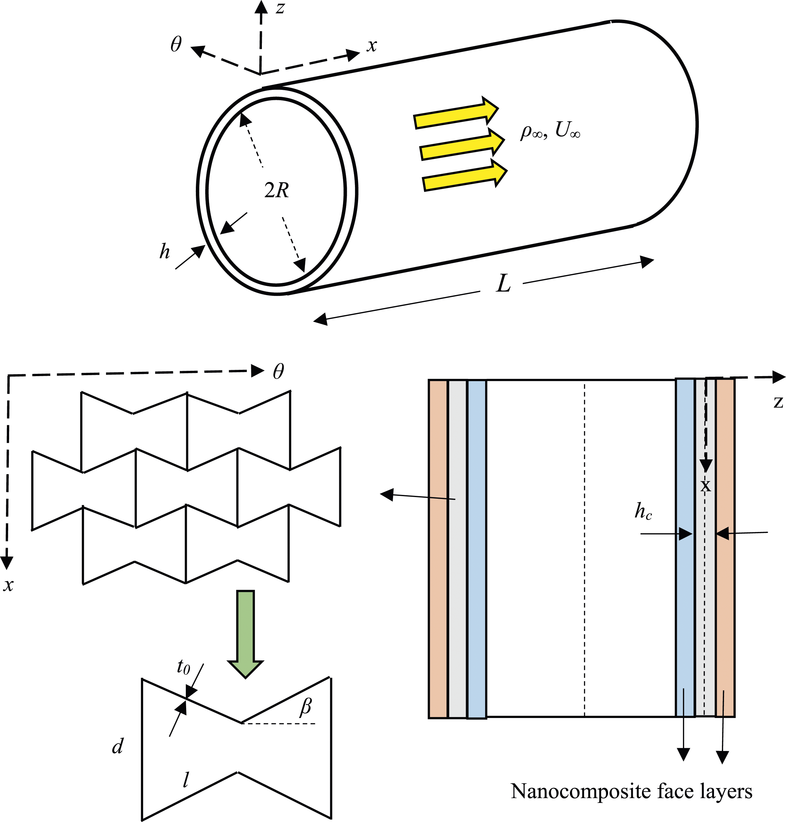
Material properties of the core
The mechanical properties (P) including the elastic modulus (E
0
), the Poisson’s ratio (ν0), and the density (ρ
0
) of the non-homogeneous material used to fabricate the AH core change from a metal-rich surface at the inner side (z = −0.5h
c
) to a ceramic-rich one at the outer surface (z = 0.5h
c
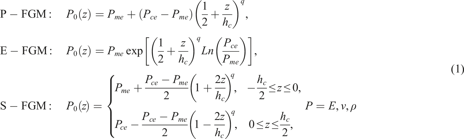
) according to either P-FGM, E-FGM, or S-FGM as described in equation (1):
For Pce/Pme = 3, the variations of material properties of the non-homogeneous material used to fabricate the AH core through the thickness direction are depicted in Figure 2 for various values of the material index. Variations of material properties of the material used to fabricate the AH core through the thickness direction.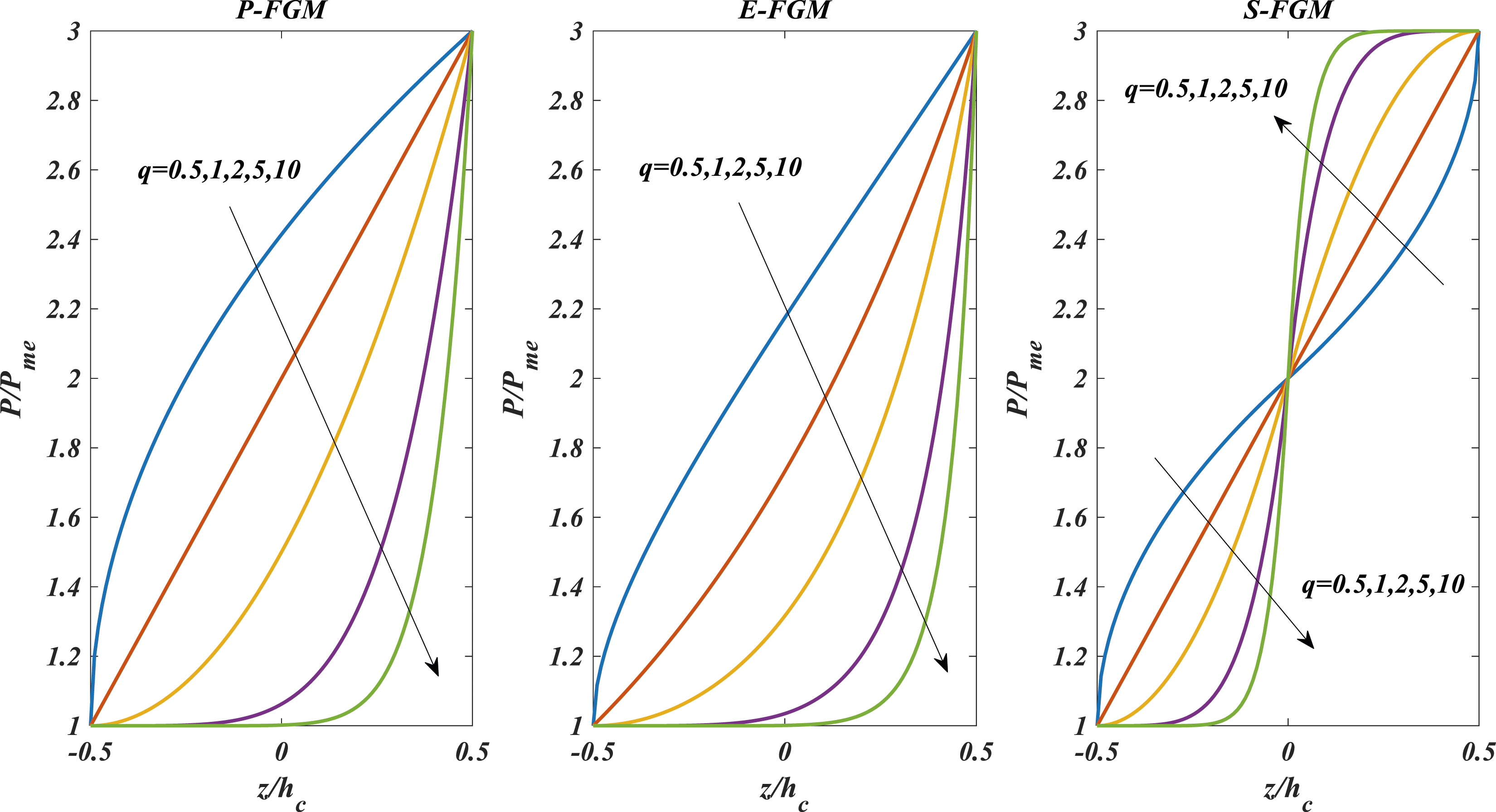
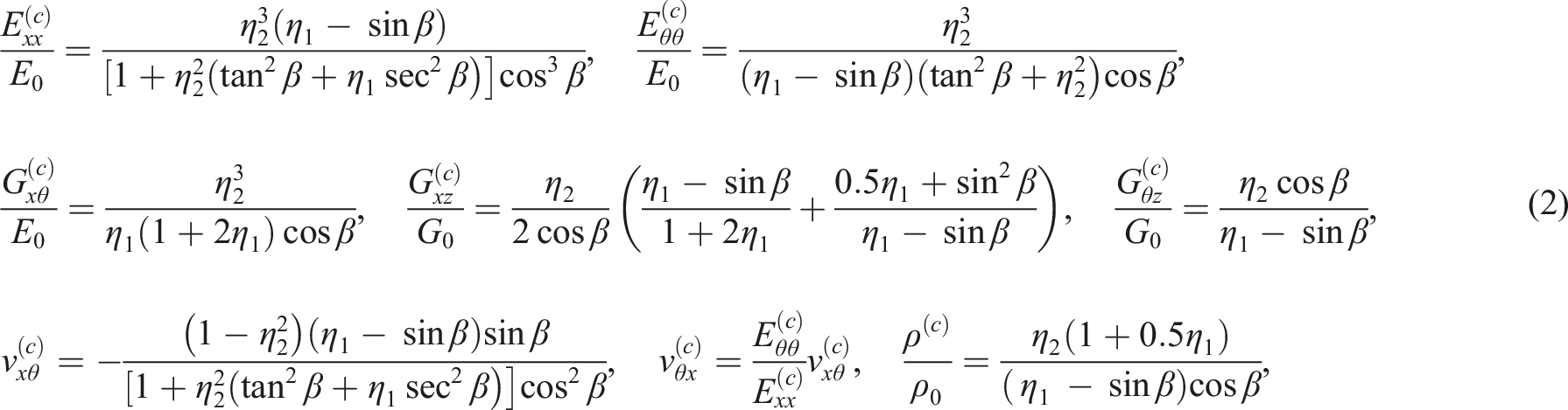
By referring to the geometric factors of an individual cell of a re-entrant FGAH structure shown in Figure 1, the density and elastic constants of the FGAH core (specified by the superscript c) are described in equation (2):
47
Material properties of the nanocomposite face layers
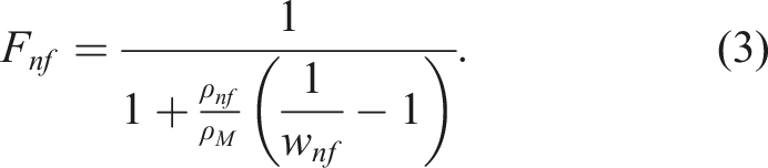
Three types of nanofillers are investigated in this paper including CNTs, GNPs, and GOPs. The nanofillers are distributed uniformly within the polymeric matrix and their volume fraction (Fnf) can be described in terms of the density of the polymeric matrix (ρ
M
), the density of the nanofillers (ρ
nf
), and the mass fraction of nanofillers (w
nf
) as presented in equation (3):
48
As stated in the rule of mixture (ROM), the density and the Poisson’s ratio of the face layers (specified by the superscript (f)) are stated in the following relations:
48

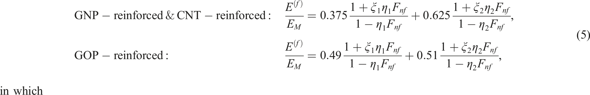
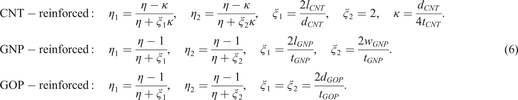
According to the Halpin-Tsai model, the equations below present the elastic modulus of the face layers:49,50
Deformation, strain, and stress
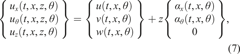
According to the FSDT presented by Naghdi and Cooper for shells, the displacement field is described as the following relation:
54
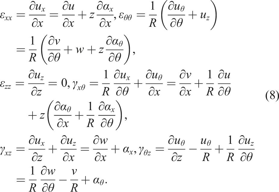
The shear (γ
ij
= 2ε
ij
) and normal (ε
ij
) components of the strain tensor are presented in equation (8):
57
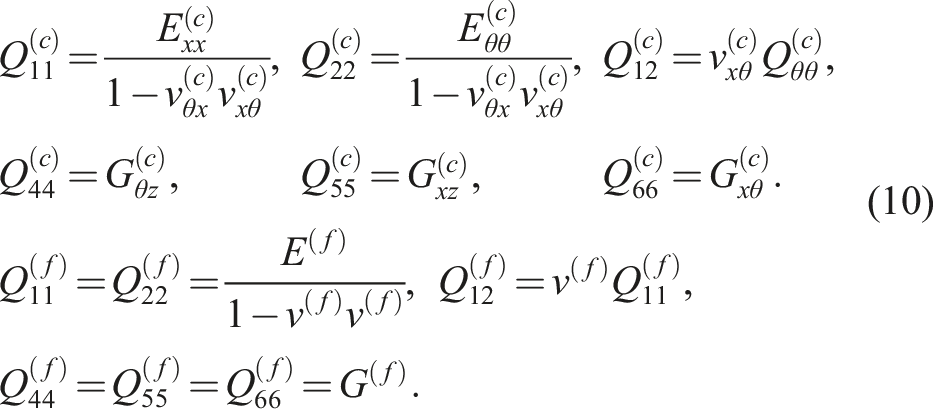
Equation (9) describes the stress tensor in the kth layer of the shell (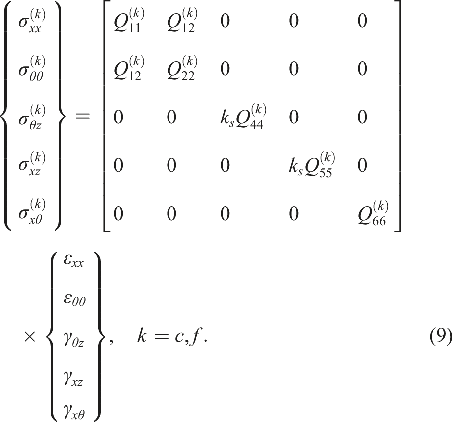
Hamilton’s principle
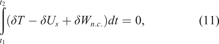
As stated in Hamilton’s principle, the following equation provides the governing equations and boundary conditions associated with the dynamic analysis of structures:
62
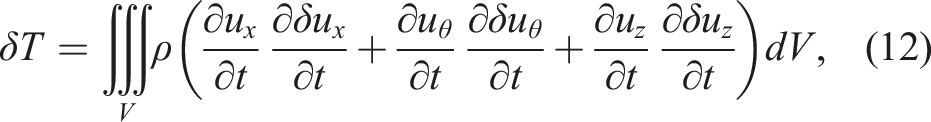
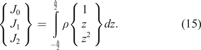
The following relation describes the variation of the kinetic energy:
62
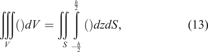
By utilizing equations (13) and (12) can be represented as follows: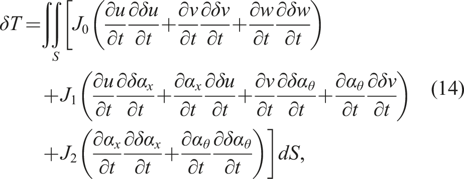
The following equation describes the variation of the strain energy:
62
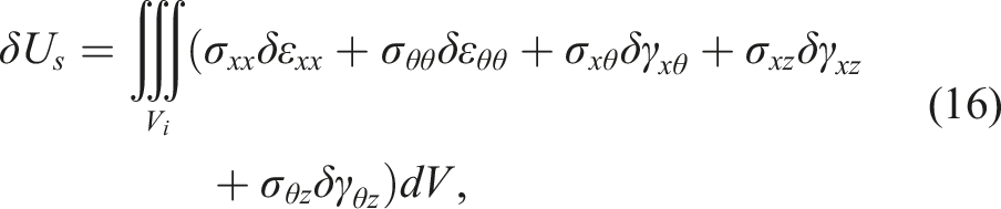
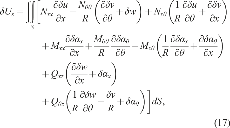
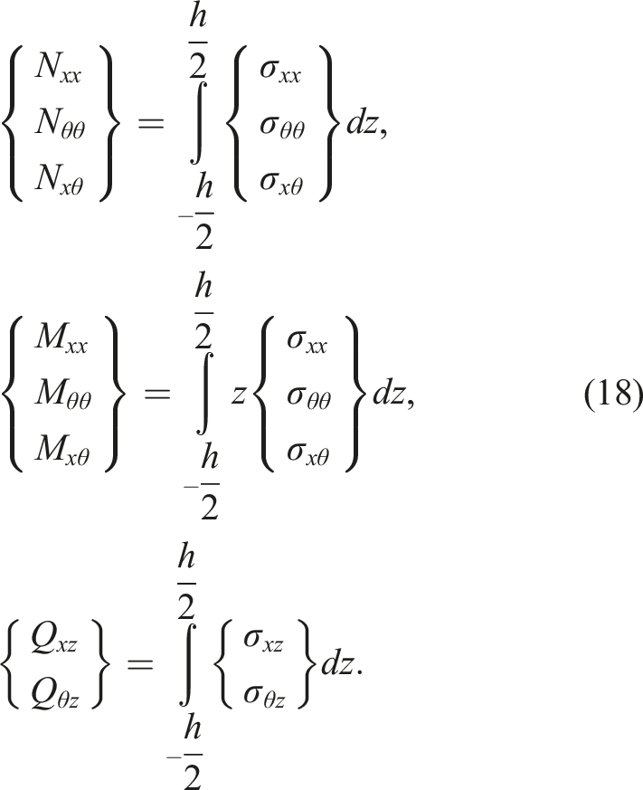
Inserting equations (8) and (9) into equation (18) results in the following relation: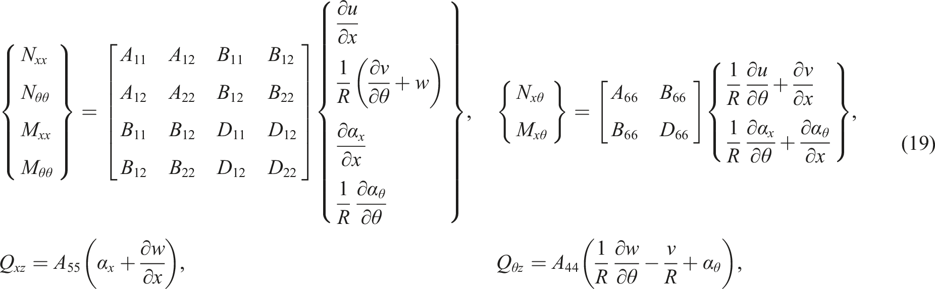
in which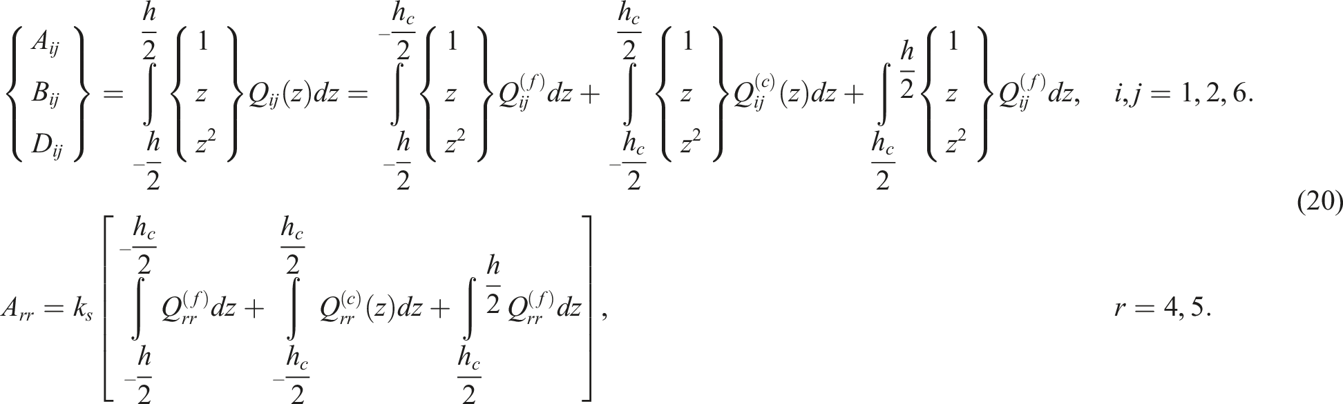
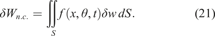
The relation below describes the variation of the work done by a non-conservative external load f distributed on the surface of the shell:
62
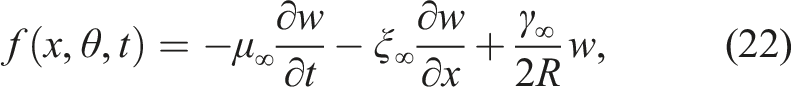
in which μ
∞
is called the aerodynamic damping coefficient, ξ
∞
is known as the aerodynamic pressure coefficient, and γ
∞
incorporates the influence of the curvature. These coefficients are presented in terms of the density and velocity of the fluid flow, Mach number (M∞), and the velocity of sound (U0) as follows: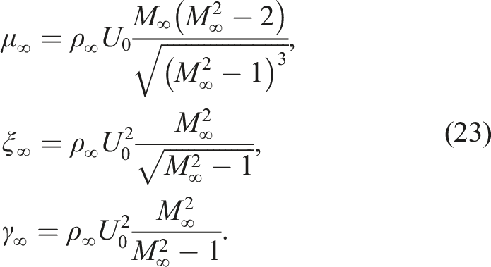
Inserting equations (14), (17), and (21) into equation (11) results in the following relations as the governing equations: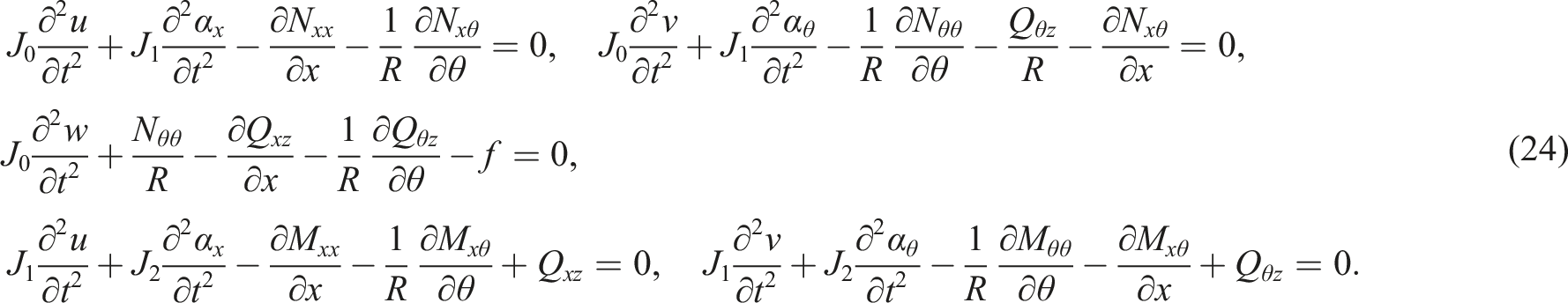
Along with the governing equation (24), the boundary conditions are attained as described in equation (25):
Semi-analytical solution
A semi-analytical solution is presented in this section for the governing equations under any combinations of the clamped, simply supported, and free conditions at x = 0 & L. The presented semi-analytical solution consists of an exact solution performed in the circumferential direction and an approximate solution performed in the axial direction.
Analytical solution in θ-direction
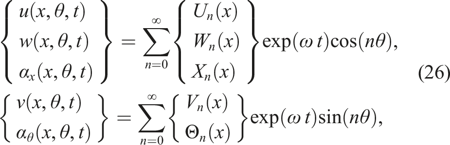
Owing to the continuity of all variables at θ = 0 & 2π, trigonometric harmonic functions (sine and cosine) can be chosen to describe all variables in the circumferential direction. The main key in the selection between either sine or cosine functions is the order of the derivatives of the variables with respect to the circumferential variable θ. Inserting equations (19) and (22) into equation (24) shows that u, w, and α
x
should be described with the same trigonometric harmonic function (e.g. cos (nθ)), and v and α
θ
should be described with the other one (e.g. sin (nθ)). Therefore, the solution below can be considered:
64
By inserting equations (19) and (22) into equation (24) and considering the solution presented in equation (26), the following relations are attained as the governing equations: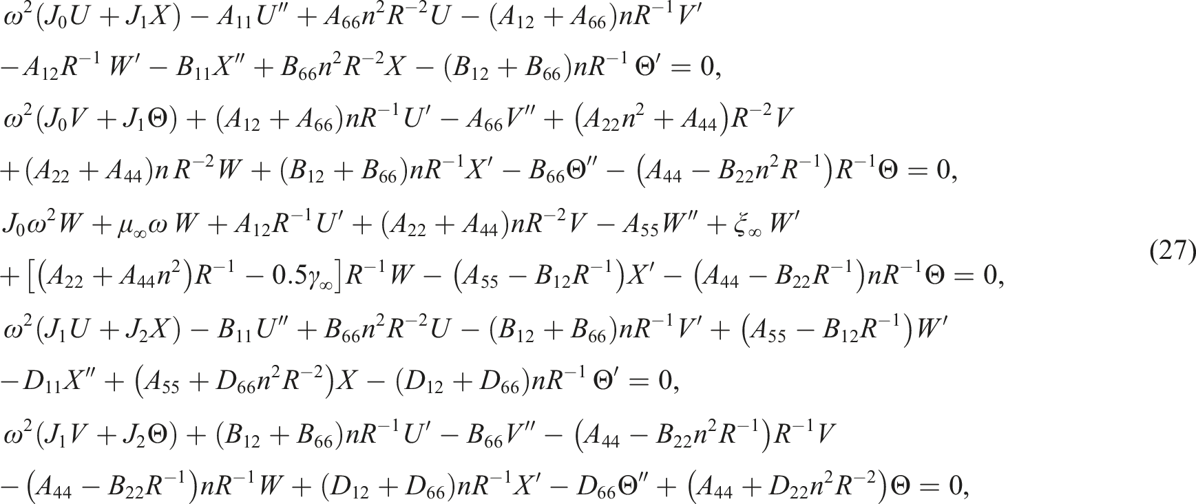
By inserting equations (19) and (26) into equation (25) and applying some simplifications, the following equations are attained as the boundary conditions: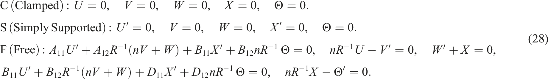
Approximate solution in x-direction
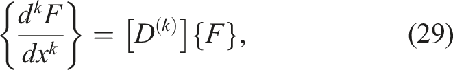
Based on the main idea of the DQM, the solution domain can be discretized to a pre-selected set of N points, and the derivative of a function like F(x) (of any order like k) is estimated in terms of the values of the function at these points. In other words, the relation below can be considered:
65
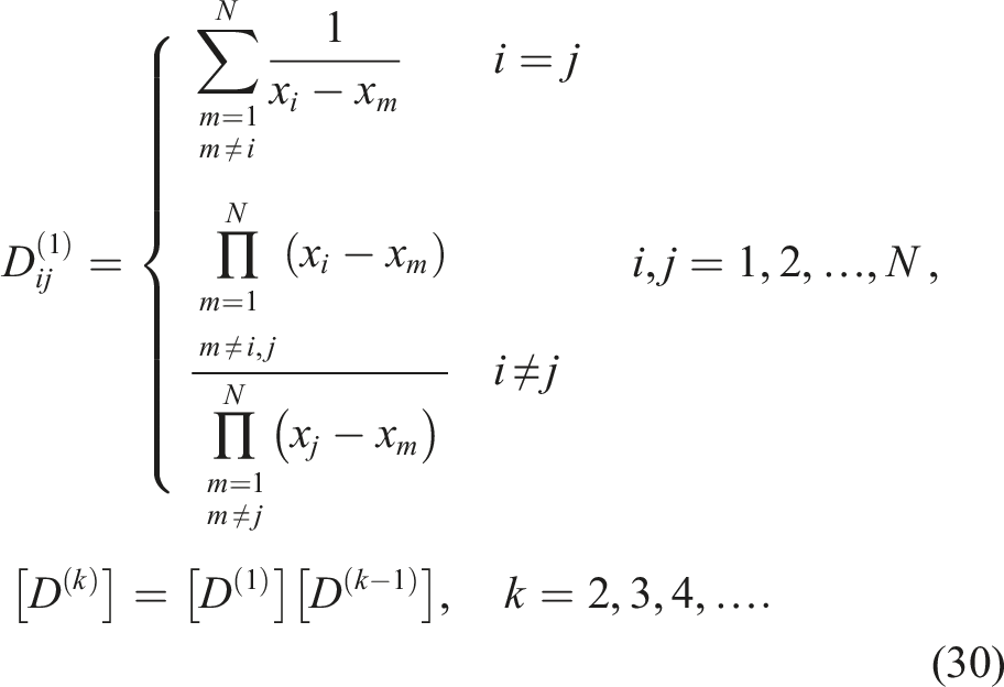
in which, as defined in equation (30), [D(k)] is a square matrix of order N known as the weighting coefficient matrix regarding the kth-order derivative:
65
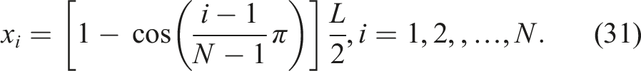
Owing to the high importance of the dispersion pattern of the grid points on the convergence of the solution performed by the DQM, the Chebyshev-Gauss–Lobatto pattern is chosen in the present work. According to this pattern the interval 0 ≤ x≤L can be discretized in a non-uniform pattern as follows:
65
By applying equation (29), the governing equation (27) are represented in the algebraic form below:
in which, as described in Appendix A,
By applying equation (29), the boundary conditions (28) are represented in the algebraic form below:
where, as presented in Appendix B, the matrix [S] is the boundary conditions matrix.
Simultaneous solutions of equations (32) and (33) lead to an inconsistency in the numbers of algebraic equations and unknown variables. To overcome this inconsistency, the set of grid points can be divided into two sets: the points located at both edges of the shell (x1 and x
N
) which are called the boundary points, and the other interior points (x2-xN-1) which are called the domain points.
64
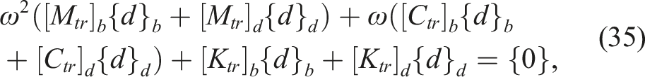
By neglecting to satisfy each of the five governing equations at the boundary points, equation (32) is stated in the following form:
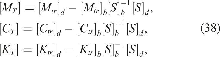
in which the subscript tr shows the non-square truncated form of the matrices. By separating the columns associated with the boundary and domain points in the mass, damping, and stiffness matrixes (equation (34) and boundary conditions matrix (equation (33), one can represent these relations as
64

where the subscripts “b” and ''d'' sequentially point to the columns of the matrixes associated with the boundary and domain points.
By inserting equation (36) into equation (35), one can attain the eigenvalue equation below:
The eigenvalues and corresponding eigenvectors can be attained through the solution of the eigenvalue equation (37). The attained eigenvalues are complex numbers and for an eigenvalue like ω
nl
, the natural frequencies (Ω
nl
) and damping ratios (ζ
nl
) can be presented in terms of the real (Re) and imaginary (Im) parts and absolute value (| |) of the eigenvalues as described in equation (39):
66
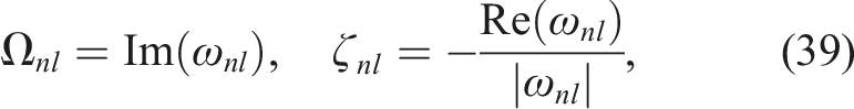
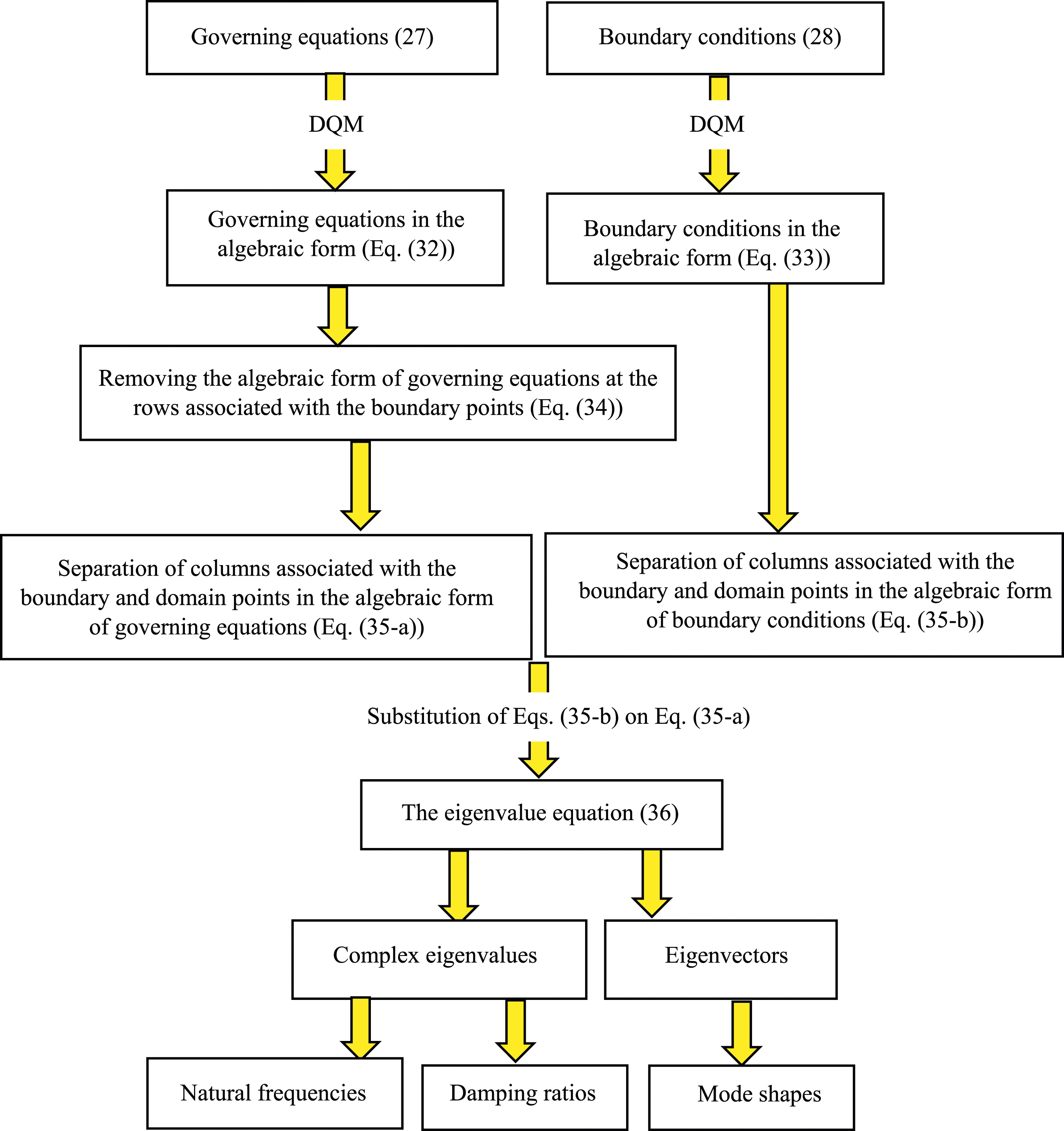
in which the first subscript (n = 0,1,2,..) is defined in equation (26) and the second one (l = 1,2,3,…) determines the sequence of modes in the axial direction. The flowchart for the solution procedure provided via the DQM is presented in Appendix C.
Numerical examples
Numerical results are presented in a dimensionless form in the current section. Two capital letters are used to show the boundary conditions at x = 0 & L, respectively. The damping ratio is innately a dimensionless parameter (equation (39)) and the dimensionless forms of the natural frequencies and aerodynamic pressure are defined as follows: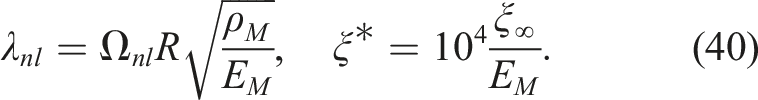
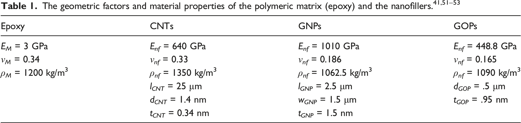
Except for the cases which are described completely, numerical examples are reported for a CS cylindrical sandwich shell of R = 0.25 m, L/R = 10, and h/R = 0.035. The AH core is fabricated from P-FGM with q = 2, h c /h = 0.75, η 1 = 2, η 2 = 0.01, β = 45° made of the composition of Aluminum (Al) of ρ m = 2700 kg/m3, E m = 70 GPa, ν m = 0.35 as metal and Alumina (Al2O3) of ρ c = 3950 kg/m3, E c = 380 GPa, ν c = 0.22 as ceramic. The nanocomposite face layers are of the same thickness with w nf = 0.01 (1 %), and their material properties can be found in Table 1. The density of the fluid flow is ρ∞ = 1.2 kg/m3 and the velocity of sound is selected as U0 = 300 m/s.
Convergence analysis
Consider a GOP-reinforced shell exposed to fluid flow of M∞ = 3. For n = 3 and l = 1,2,…,6, the variations of damping ratios and dimensionless natural frequencies versus the variation of the number of grid points in the DQM are depicted in Figure 3. As observed, the presented numerical solution via the DQM benefits from high convergence. In what follows, all numerical examples are presented for N = 15. Convergence analysis of the numerical solution provided by the DQM.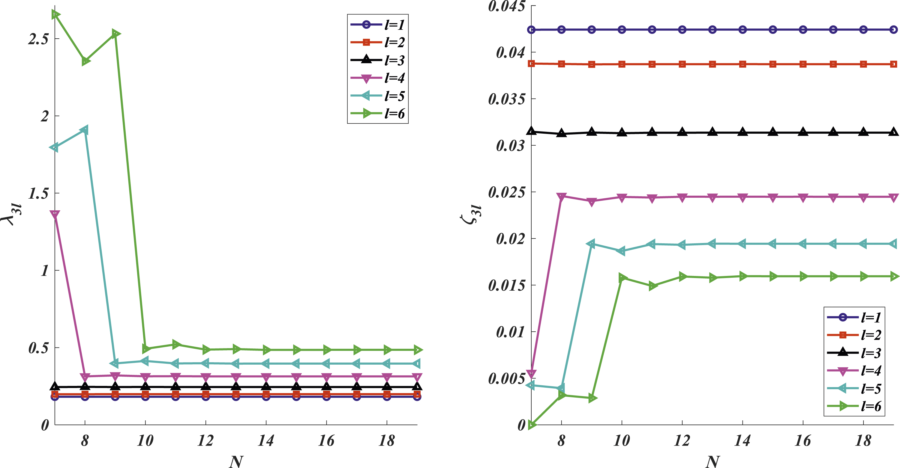
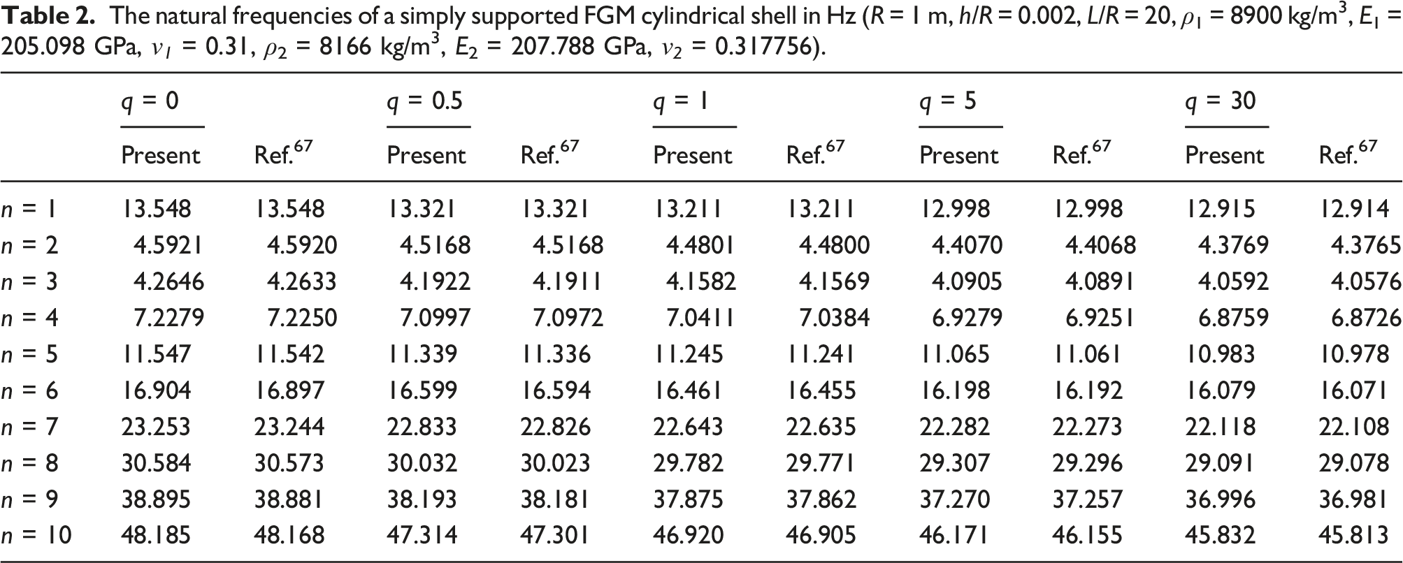
Verification
The natural frequencies of a simply supported FGM cylindrical shell in Hz (R = 1 m, h/R = 0.002, L/R = 20, ρ1 = 8900 kg/m3, E1 = 205.098 GPa, ν 1 = 0.31, ρ2 = 8166 kg/m3, E2 = 207.788 GPa, ν 2 = 0.317756).
Parametric study
In the current section, a parametric study is presented to inspect the relationships between the flutter boundaries and several factors. By increasing the aerodynamic pressure of the fluid flow, the natural frequencies and damping ratios of the shell are affected in all vibrational modes (n = 0,1,2,… & l = 1,2,3,…).
As the velocity of fluid flow (M∞) grows from zero, both the aerodynamic damping coefficient and the aerodynamic pressure coefficient increase (equation (23)). On the one hand, the aerodynamic damping coefficient improves the stability of the shell, on the other hand, the aerodynamic pressure coefficient tends to destabilize the shell. For small Mach numbers, the aerodynamic damping coefficient is dominant, and the stability of the shell increases by increasing the velocity of fluid flow. However, by increasing the Mach number to higher values, the aerodynamic damping coefficient reaches a specific value (μ∞→ρ∞U0) and the aerodynamic pressure coefficient grows steadily. As a result, the damping ratios of the shell experience an initial small growth followed by an intense reduction. In flutter analysis, the variations of the damping ratios and natural frequencies of the shell are depicted versus the variation of the aerodynamic pressure in various vibrational modes. The lowest value of the aerodynamic pressure which results in a negative damping ratio in a vibrational mode is selected as the critical aerodynamic pressure ( The mode shapes of the shell associated with the vibrational modes involved in flutter.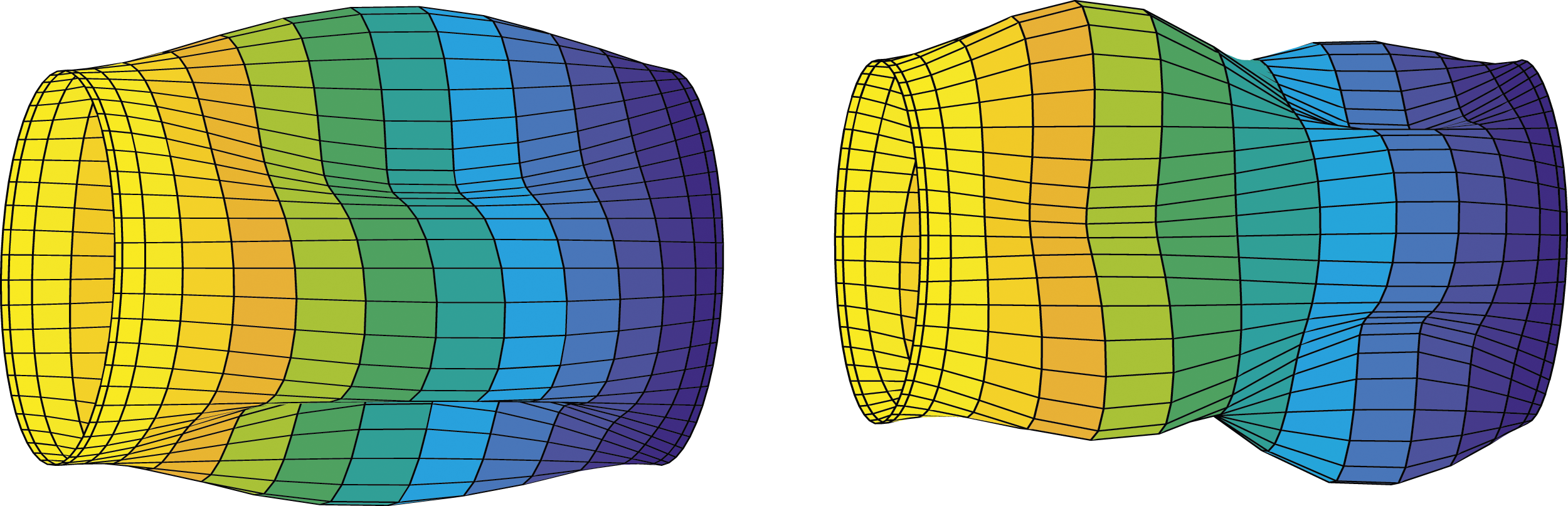
Figure 5 shows the flutter boundaries for a cylindrical sandwich shell with an FGAH core and nanocomposite face layers enriched with either CNTs, GNPs, or GOPs with the same mass fraction. As Figure 5 shows, the dimensionless critical aerodynamic pressure for the shells with CNT-reinforced face layers, GOP-reinforced face layers, and GNP-reinforced face layers are 2.06, 2.70, and 4.27, respectively. As shown, the highest natural frequencies and critical aerodynamic pressure belong to the shell with GNP-reinforced face layers. Two reasons can be mentioned for the superiority of GNP-reinforced face layers. As the first reason, as shown in Table 1, GNPs benefit from higher elastic modulus than the GOPs (EGNP/EGOP≈2.25) and the CNTs (EGNP/ECNT≈1.58). As the second reason, it should be noted that the GNPs benefit from bigger specific surface areas rather than GOPs and CNTs which results in a stronger bonding between the polymeric matrix and the nanofillers and consequently a better reinforcing effect. It should be noted that in the present work, the superiority of GNPs is only concluded based on better aeroelastic stability characteristics of the shell. This superiority may be affected by the involvement of other factors such as the thermo-mechanical stress analysis, fatigue characteristics, manufacturing limitations, cost-effectiveness, etc. The influences of the type of nanofillers in the face layers on the flutter boundaries.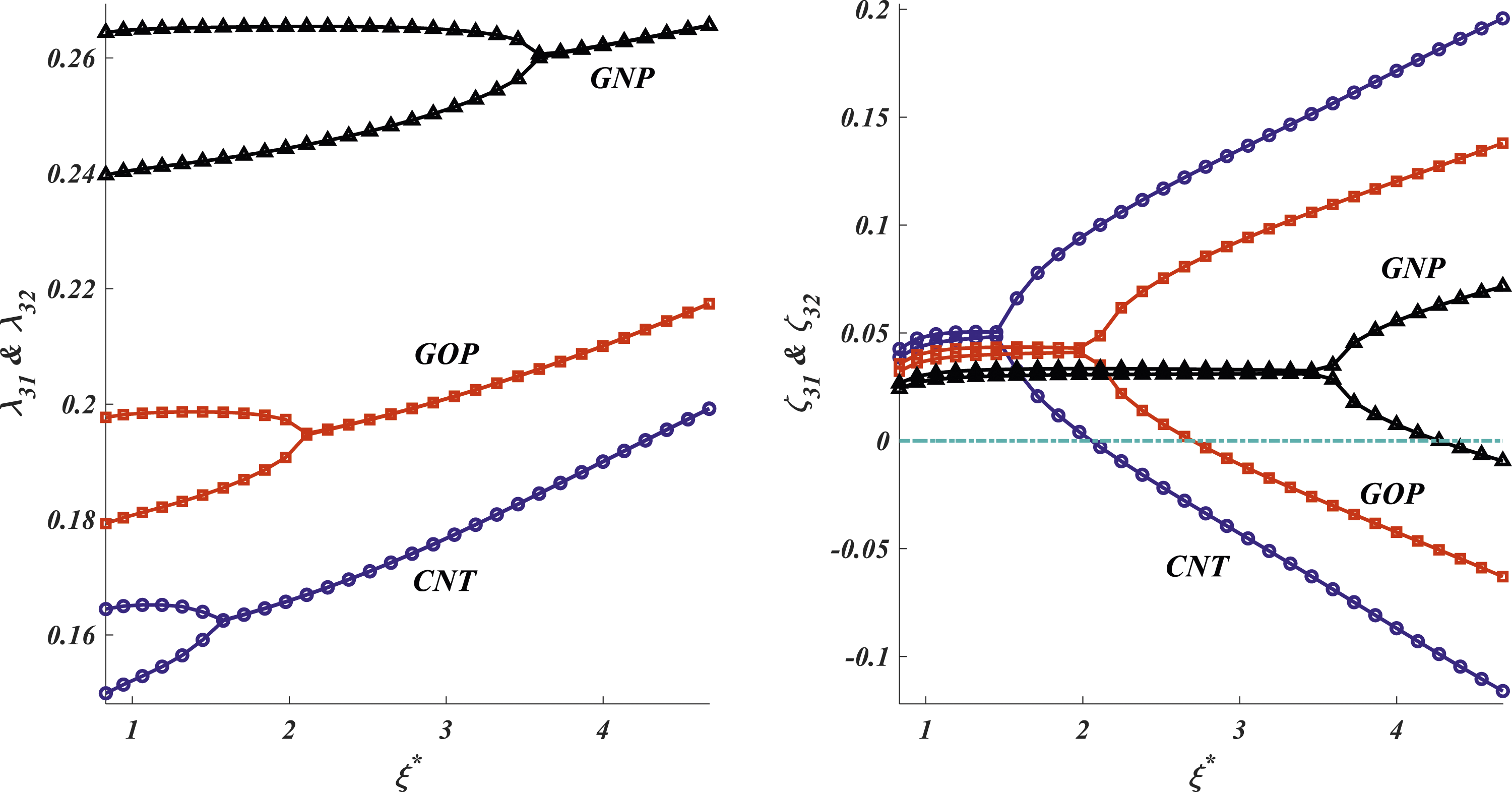
Table 1 shows that the CNTs benefit from higher elastic modulus than the GOPs (ECNT/EGOP≈1.43). However, Figure 5 shows that the dimensionless critical aerodynamic pressure is higher for the shell with GOP-reinforced face layers rather than the shell with CNT-reinforced face layers. It reveals that the bigger specific surface areas of the GOPs than the CNTs compensate for their lower elastic modulus. Since the rends are the same, in what follows, all numerical examples are prepared for the shell with GOP-reinforced face layers.
Figure 6 is devoted to examining the effects of the type of FGM utilized to fabricate the AH core on the flutter boundaries. As shown in this figure, the dimensionless critical aerodynamic pressure for the shells with the AH core fabricated from E-FGM, P-FGM, and S-FGM are 2.67, 2.70, and 2.74, respectively. In other words, the highest critical aerodynamic pressure (not necessarily the highest natural frequencies) belongs to the shell with an AH core fabricated from S-FGM and the lowest one belongs to the shell with an AH core fabricated from E-FGM. The influences of the type of FGM material utilized to fabricate the AH core on the flutter boundaries.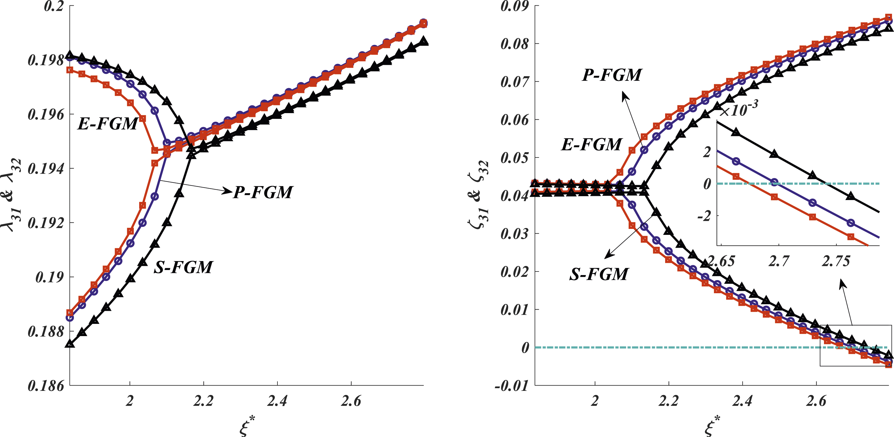
A comparison between Figures 5 and 6 reveals that the dependency of the natural frequencies and the flutter boundaries on the type of nanofillers utilized to reinforce the face layers is significantly stronger than the dependency of the natural frequencies and the flutter boundaries on the type of the FGM utilized to fabricate the AH core. The reason behind this is that the high percentage of the flexural rigidity of the shell comes from its face layers and the FGAH core has a weak effect on the flexural rigidity of the shell.
By considering a specific value for the total thickness of the shell, Figure 7 shows the impacts of the thickness of the FGAH core on the flutter boundaries. Utilizing equations (1), (2), and (4) and the values presented in Table 1, it can be shown that for this case of study, the mean density of the FGAH core and the density of the GOP-reinforced face layers are ρ
c
= 68.2 kg/m3 and ρ
f
= 1198.8 kg/m3, respectively. Thus, a small increase in the thickness of the FGAH core significantly reduces the mass of the shell. As shown in Figure 7, this reduction in the mass of the shell brings about higher natural frequencies. In comparison with the nanocomposite face layers, the FGAH core has smaller elastic and shear moduli. As a result, growth in the thickness of the FGAH core and a reduction in the thickness of the nanocomposite face layers reduce the stiffness of the shell which results in lower stiffness of the shell and consequently lower critical aerodynamic pressure. The influences of the thickness of the FGAH core on the flutter boundaries.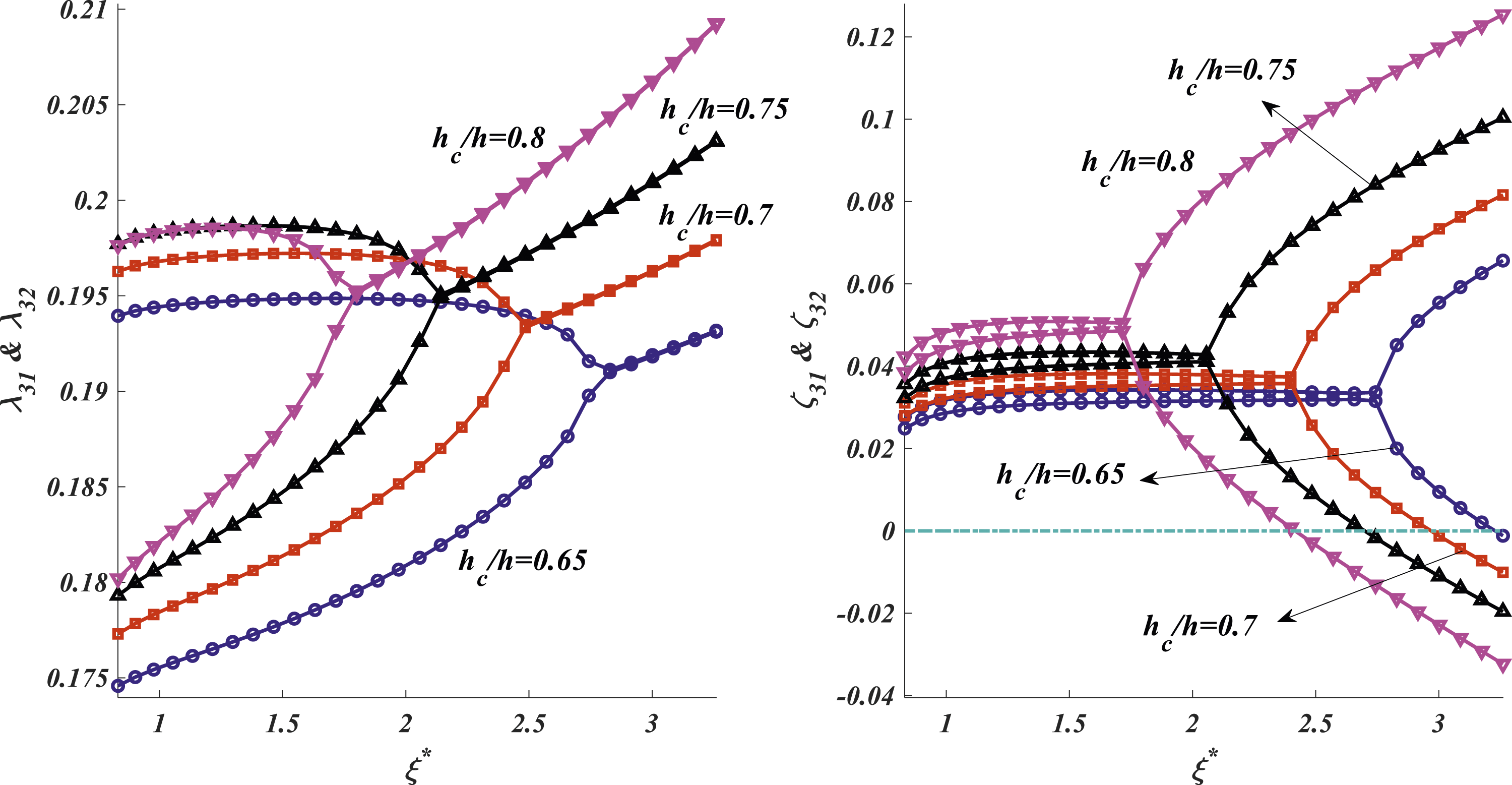
The impacts of the material index in the FGAH core on the flutter boundaries are inspected in Figure 8. According to equation (1) and Figure 2, growth in the material index increases the volume fraction of the metal phase (Al) and reduces the volume fraction of the ceramic phase (Al2O3) in the P-FGM core. Thus, an increase in the material index leads to lower shear and elastic moduli of the core which reduces the stiffness of the shell. As a result, when the FGAH core is of P-FGM type, the critical aerodynamic pressure diminishes by growing the material index. The authors’ investigations reveals that the same trend can be seen for the effect of the material index in the FGAH on the critical aerodynamic pressure for the shells with the AH cores made of E-FGM or S-FGM. Figure 8 shows that for high values of the material index in the FGAH core (q→∞), the critical aerodynamic pressure reaches a constant value which belongs to a sandwich shell with an AH core fabricated from the metal phase (Al). It should be noted that the effect of the material index on the natural frequencies and the flutter boundaries may be affected by the material selected as the metal and ceramic phases. The influences of the material index in the FGAH core on the flutter boundaries.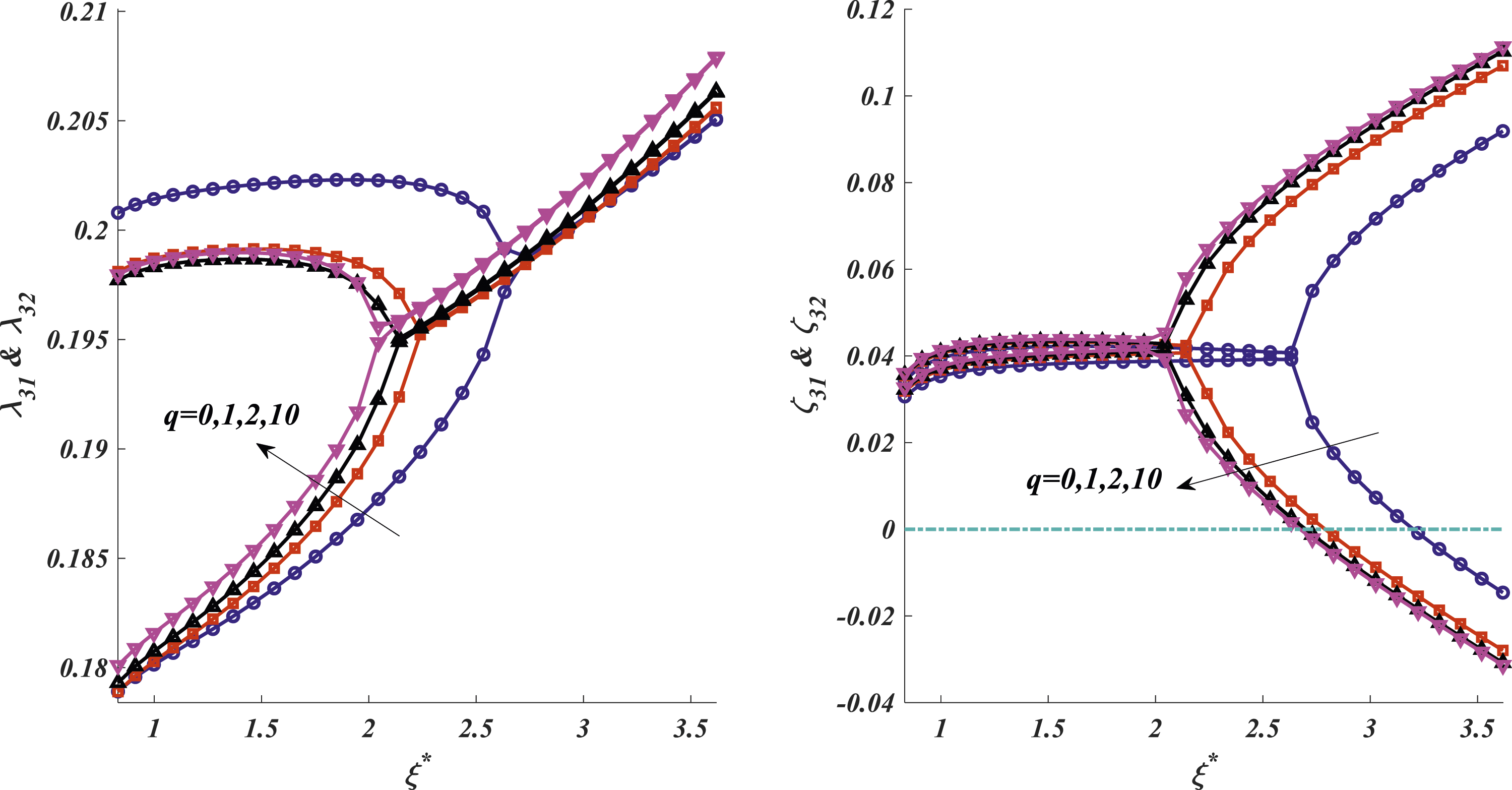
Figure 9 is devoted to investigating the influences of the mass fraction of the nanofillers in the face layers on the flutter boundaries. As Table 1 shows, all types of nanofillers benefit from remarkably higher elastic moduli than the polymeric matrix. Meanwhile, there are small differences between the density of all types of nanofillers and the density of polymeric matrix. Thus, a small increase in the mass fraction of the nanofillers results in a significant increase in the stiffness-to-mass ratio of the shell and consequently considerable improvements in the natural frequencies and critical aerodynamic pressure. The influences of the mass fraction of the nanofillers in the face layers on the flutter boundaries.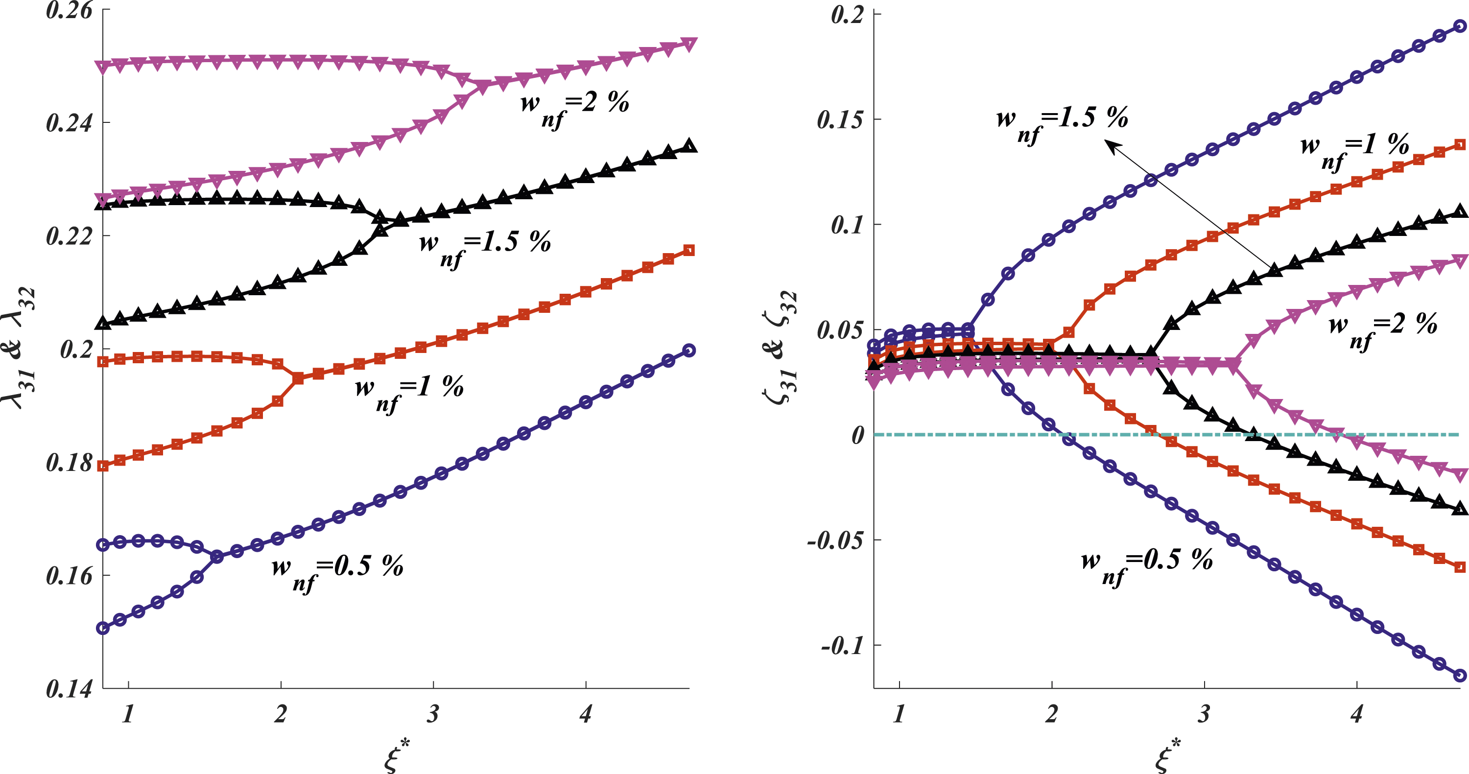
The influences of the inclined angle in the FGAH core on the flutter boundaries are inspected in Figure 10. The authors’ investigations on equation (2) reveal that as the inclined angle grows from zero to 90°, The influences of the inclined angle in the FGAH core on the flutter boundaries.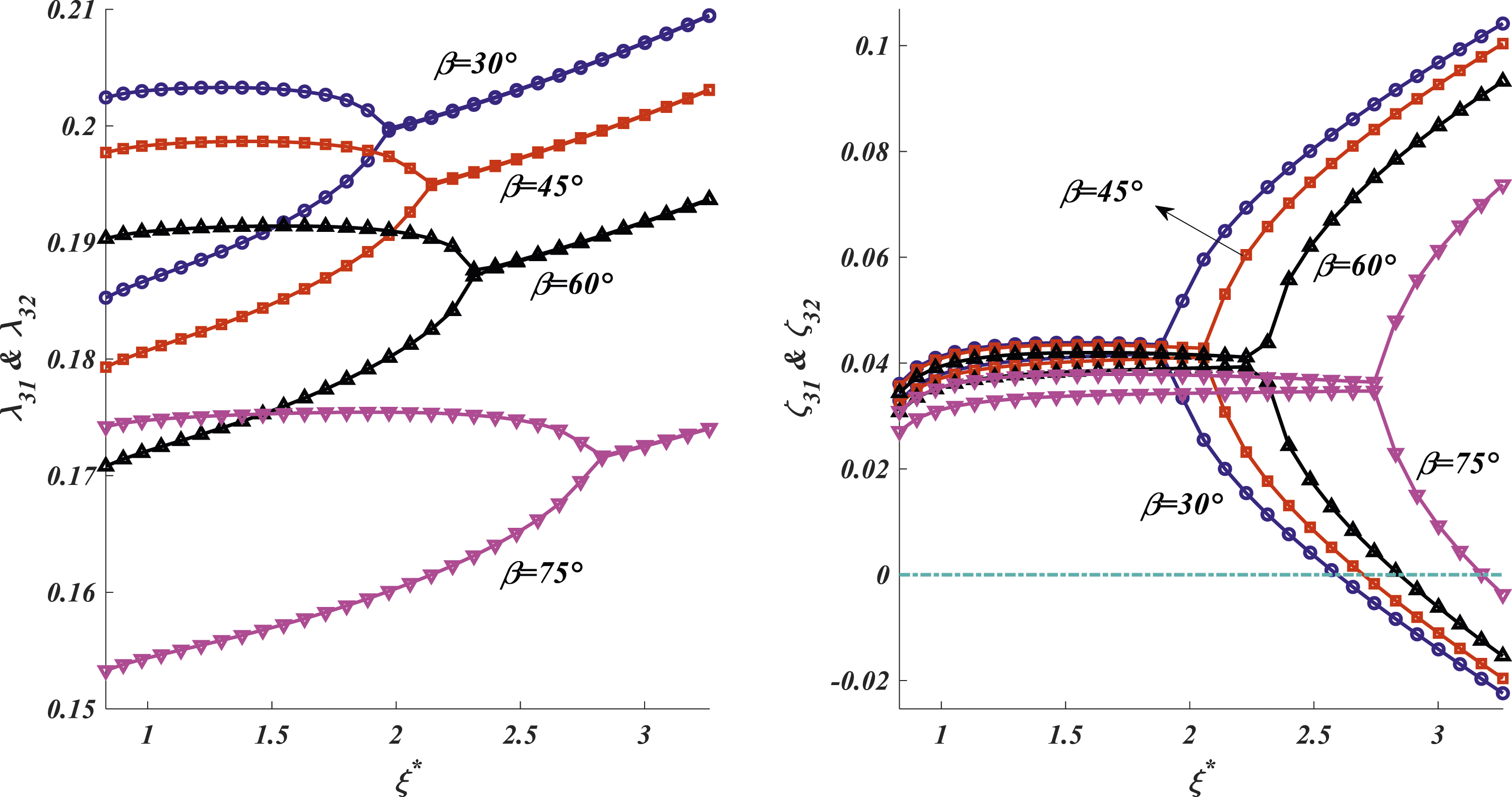
The flutter boundaries can be easily influenced by the boundary conditions of the shell which is investigated in Figure 11. As presented in equation (25), the boundary conditions can be arranged as clamped, simply supported, and free in order to reduce the degrees of freedom (DOF) at the edges of the shell and provide more restriction at the edges of the shell. In other words, utilizing the clamped condition brings about lower DOF at the edges of the shell and higher stiffness than using the simply supported one, and utilizing the simply supported condition results in lower DOF at the edges of the shell and higher stiffna0ess rather than using the free one. As Figure 11 shows, the highest critical aerodynamic pressure belongs to the CC shell and the lowest critical aerodynamic pressure belongs to the CF shell. As a result, it can be concluded that employing the more restricted conditions at the edges of the shell (utilizing a clamped edge than a simply supported one and utilizing a simply supported edge than a free one) brings about higher stiffness and consequently better aeroelastic stability. The influences of the boundary conditions on the flutter boundaries.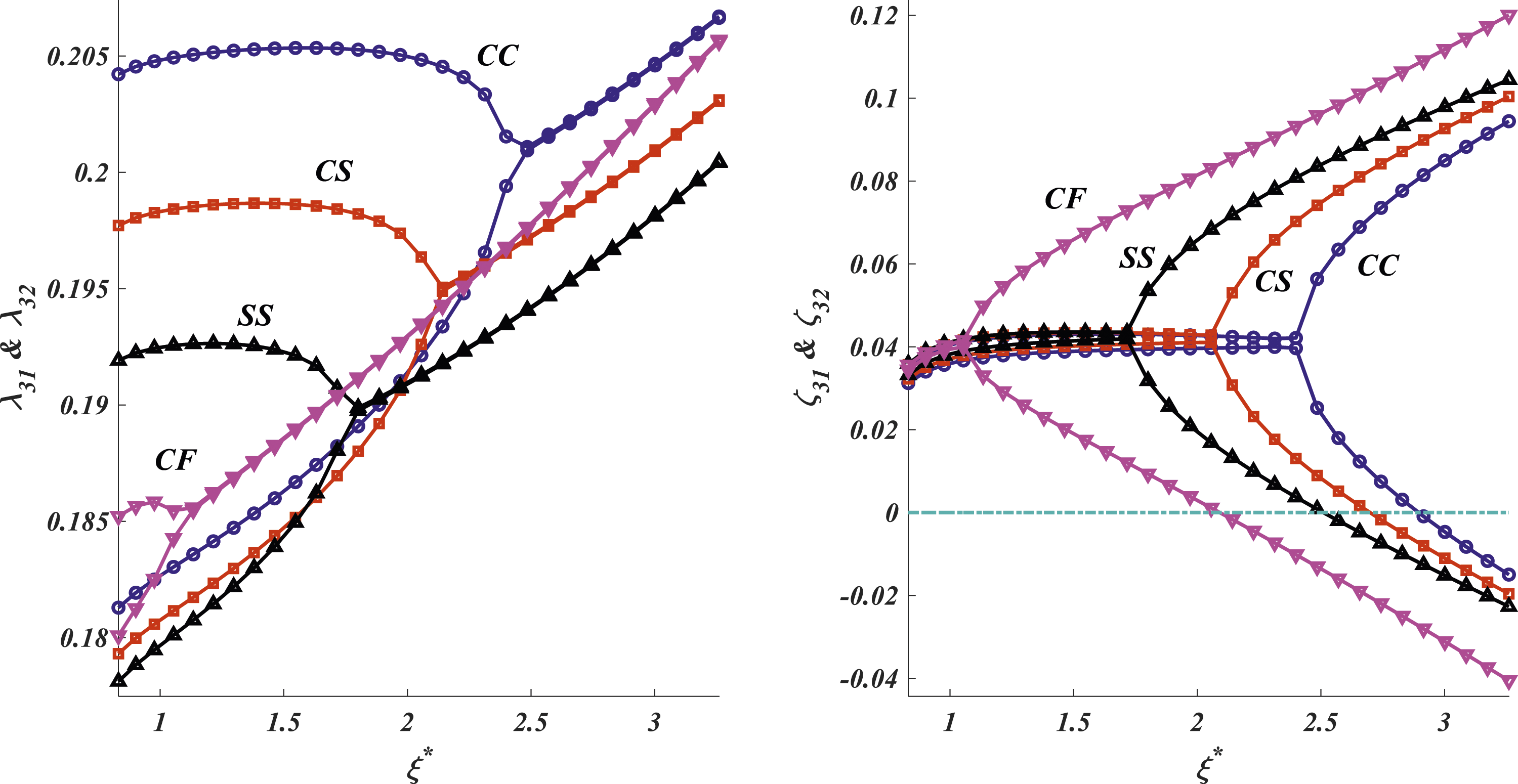
Conclusions
The supersonic flutter analysis was investigated for a cylindrical sandwich shell with a re-entrant FGAH core covered with two polymeric face layers enriched with either CNTs, GNPs, or GOPs. The shell was modeled based on the FSDT and the aerodynamic pressure was modeled via the piston theory. The corresponding damping ratios and natural frequencies were calculated and the influences of various factors on the natural frequencies and the critical aerodynamic pressure of the shell were investigated. The main findings of the presented work can be listed as follows: • Due to the higher elastic modulus and higher specific surface areas of the GNPs than the GOPs and CNTs, the highest critical aerodynamic pressure and natural frequencies belong to the shell with GNP-reinforced face layers. • The lower elastic modulus of the GOPs than the CNTs can be compensated by bigger specific surface areas of the GOPs. Thus, a shell with GOP-reinforced face layers has better aeroelastic stability behavior than a similar one with CNT-reinforced face layers. • The highest critical aerodynamic pressure belongs to the shell with an AH core fabricated from S-FGM and the lowest one belongs to the shell with an AH core fabricated from E-FGM. • The natural frequencies and the flutter boundaries are more dependent on the type of nanofillers utilized to enrich the face layers rather than type of the FGM utilized to fabricate the AH core. • By considering a specific value for the total thickness of the shell, a small increase in the thickness of the FGAH core increases the natural frequencies of the shell and reduces its critical aerodynamic pressure. • When the FGAH core is made of the composition of Aluminum and Alumina, a reduction in the percentage of the ceramic phase (Alumina) results in lower critical aerodynamic pressure. • A small increase in the mass fraction of the nanofillers brings about significant increases in the natural frequencies and critical aerodynamic pressure of the shell. • An increase in the inclined angle of the cells in the FGAH core reduces the natural frequencies of the shell and increases its critical aerodynamic pressure. • By using the more restricted conditions at the boundaries of the shell, higher critical aerodynamic pressure can be attained.
Footnotes
Declaration of conflicting interests
The author(s) declared no potential conflicts of interest with respect to the research, authorship, and/or publication of this article.
Funding
The author(s) received no financial support for the research, authorship, and/or publication of this article.
Data availability statement
The data that support the findings of this study will be available upon reasonable request.
Appendix A
in which [0] and I respectively represent the zero and identity matrix of order N, and k11-k55 are defined in equation (A-2):
Appendix B
in which S11-S55 describe the condition at x = 0:
where the subscript 1 points to the first row of each matrix.
S61-S105 describe the condition at x = L:
where the subscript N points to the last (Nth) row of each matrix.
Appendix C
Flowchart for the solution procedure.