
Abstract
The in-arm hydro-pneumatic suspension unit (ISU), comprising mainly a hydro-pneumatic spring and vane damper units, is a typical suspension system. Owing to the excellent damping properties of its hydro-pneumatic suspension unit, the ISU has not only been applied to tracked vehicles but can also be adopted in various other vehicle types. In this study, we evaluate the applicability of the ISU in enhancing tank maneuverability and turret stability during dynamic operations. Specifically, a mathematical model is first established for kinematic analysis of the tank’s internal suspension elbow structure, followed by an adjustable damper flow orifice design to improve the stability of the tank chassis. Using the linear matrix inequality (LMI) approach, this orifice design is modeled as a multi-objective
Keywords
Introduction
Combat vehicles, especially tanks and armored vehicles, are large objects typically weighing up to several tons. Due to the poor road conditions typically encountered during their operation, turret stability is often poor and the ride comfort for the crew is also lacking. In the past decades, considerable effort has been devoted to improving the smoothness and stability of these vehicles. As early as 1974, Crosby et al. 1 proposed using controllable dampers to suppress vehicle impact and vibration. Limited by the technical conditions at the time, researchers generally used passive torsion bar suspension systems to improve the ride comfort of combat vehicles.2,3 However, since neither the damping coefficient nor the elastic coefficient could be adjusted in these systems, the side-tumbling stability of the torsion bar suspension system was not satisfactory. Consequently, controllable hydro-pneumatic suspensions have attracted widespread attention in recent years.
Generally, hydro-pneumatic suspension systems can be divided into three categories: fixed-cylinder type, swing type, and in-arm suspension units (ISUs). 4 They share the same basic accumulator and shock-absorber principles; the only differences lie in the actuating-cylinder structure and how it connects to the vehicle body. Yang et al. 5 propose a model-predictive control method for a semi-active hydro-pneumatic inerter-based suspension: a fluid inerter is added to the suspension, and damping is achieved by adjusting the hydraulic-valve opening. Cai et al. 6 introduce a finite-frequency design that handles band-limited disturbances and actuator-input delays in active suspension control, achieving superior disturbance rejection within the selected frequency range compared to traditional full-band active methods. Jan 7 present an improved dual-tube hydraulic damper that incorporates variations in oil bulk modulus into the control model, enhancing ride comfort under small-amplitude, high-frequency excitations. Ren et al. 8 develop an adaptive sliding-mode controller for semi-active suspensions by combining sky-hook and ground-hook logic via a virtual reference model and estimating states with an unscented Kalman filter; however, they do not account for actuator delays, leaving real-time observer accuracy unguaranteed.
For tracked off-road tanks, proper suspension design is more important than in passenger cars because their dynamic behavior is completely different. 9 Due to the high frequency of off-road driving, the interaction between tire and terrain must be considered in order to accurately analyze vehicle handling. 10 In addition, compared with other vehicles, the structure of the tank is more specialized, which requires more space-saving suspension, more flexible design, and more convenient maintenance. To address this problem, multi-objective optimizations should be carried out to find a design solution that optimizes all performance indices simultaneously. Specifically, ISU adopts an elbow structure and converts the linear compression of the damper into a rotary form; compared with the fixed cylindrical structure, this releases physical constraints and can be configured as a semi-active or active suspension. Owing to this property, ISU has attracted extensive research interest over the past years. Wu 11 analyzed the vehicle motion of a wheeled armoured fighting vehicle using an ISU model, and Oscarsson 12 conducted a parameter study of ISU for a heavy multi-axle vehicle using a full-vehicle model. However, these studies did not perform design optimization for ISU. Nguyen et al. 13 proposed an “on-off” damper strategy and an in-plane model to obtain the optimal damping coefficient, and used a standard PID controller for damping control. Results also verified the superior performance of the semi-active damper in experiments conducted on a suspension test rig.
However, it is worth noting that most of these semi-active suspension systems reported for tracked vehicles adopt two-state dampers (on-off type), and most practical physical constraints, e.g., the dynamic and static load ratios for ensuring vehicle grounding and the scope for actuator stroke, are omitted. In practice, however, such constraints may largely impact these suspension systems, degrade the system control performance, or even cause the controller to be ineffective in real vehicles. In this paper, we evaluate the feasibility of ISU in tanks for improving ride comfort while maintaining maneuverability, taking all physical constraints into account. As an efficient method for convex optimization problems with multiple constraints, the linear matrix inequality (LMI) approach is adopted to solve the ISU disturbance rejection problem under multiple constraints. We first establish a mathematical model to analyze the kinematics of the tank elbow internal suspension structure, and then utilize the LMI optimization approach to model the orifice design for the ISU system control with all hardware constraints taken into account. Finally, both simulations and experiments are conducted to verify the effectiveness of the proposed controller in different cases.
The remainder of this paper is organized as follows. First, the structure and kinematic model for the tank elbow internal suspension system in this paper are introduced. Then, the mathematical model of the ISU is derived. Next, an ISU system performance improvement mechanism based on LMI optimization is proposed. Finally, simulations and experiments of the ISU are conducted.
Analysis and modeling of tank elbow internal suspension structure
Suspension structure
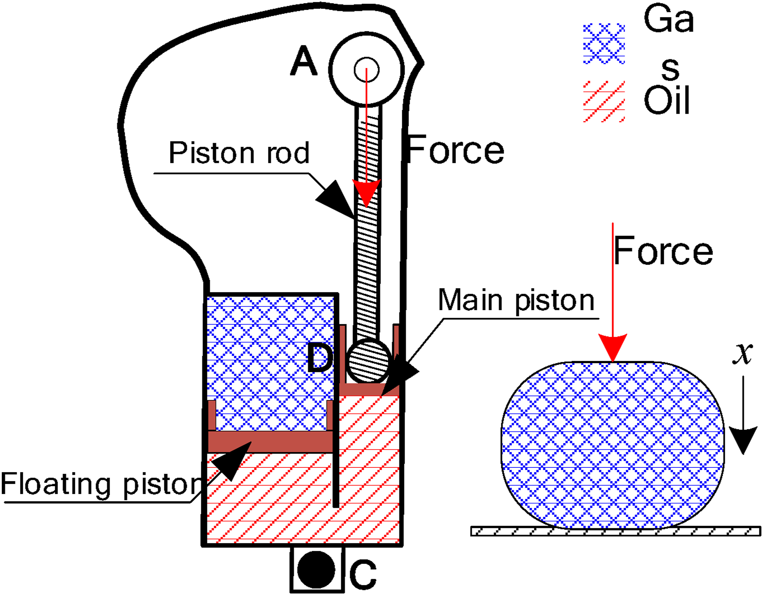
Figure 1 presents a representative ISU system utilized for tanks, which consists mainly of a hydro-pneumatic spring and a controllable blade damper. As shown in Figure 1(a), the hydro-pneumatic spring includes a high-pressure chamber, a floating piston, a main piston, and a piston-connecting rod, while the blade damper comprises a rotating blade, a fixed diaphragm, an equalizing oil passage, and a servo-valve control structure. In this system, semi-active damping control is realized by the servo valve; by adjusting its opening size, the damping force can be changed dynamically. The balancing elbow and the actuating cylinder of the hydro-pneumatic spring are integrated, with axis point O serving as the rotation center of the balance elbow. Point A denotes the top of the piston rod of the actuating cylinder, and point C indicates the wheel axle. The controllable damper is mounted at the upper end of the elbow body, and its damper-disc axis is coaxial with the balance elbow. During vehicle operation, external forces act vertically along the axis through point C. One end of the piston-rod connecting rod (Point A) is hinged to the suspended upper arm, while the other end (Point D) connects to the main piston via a ball hinge. Figure 1(b) provides a top view of the ISU system designed for this study. A representative ISU system for tanks. (a) Sketch of the ISU, (b) a top view of the ISU system.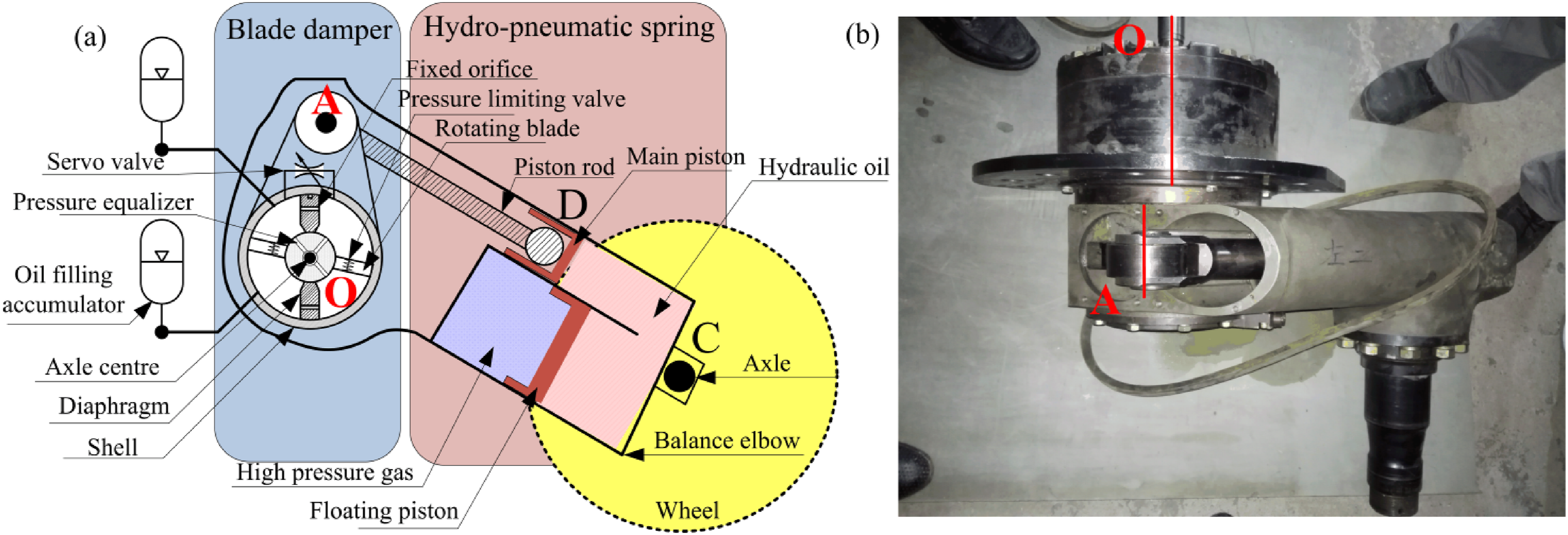
Kinematic analysis
In this section, a mathematical model is established for the internal elbow suspension system based on the simplified hydro-pneumatic guide rod suspension system structure. The relationships among the structural parameters, displacements, and forces are also analyzed. Below are some assumptions made for the modeling. (1) The inner parts of the suspension system are in a good sealing state; (2) When oil is flowing inside the cylinders, both pressure drops and cavitation are not considered; (3) Only single wheel movement is considered while the hinges between those wheel tracks are omitted.
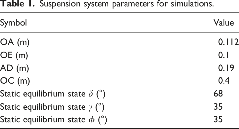
To facilitate the suspension kinematics analysis, the structural diagram of the main ISU components shown in Figure 1 is simplified to the planar connecting rod diagram shown in Figure 2. The ISU structure parameters are listed in Table 1. Linkage planar diagram with suspended structure, where point O is the axis of the balance elbow (OC), which is fixedly connected with the vehicle body, and the C point is the wheel axle. The A (A0) point is the top position of the piston rod of the actuating cylinder, which is fixed relative to the vehicle body. Point A′ is the position assuming that after the A0point rotates α around O. Point B is the intersection of the center line of the actuating cylinder and the extension line of OC. Point D is the position of the ball head of the piston connecting rod of the actuating cylinder. OE represents the force arm of the actuating cylinder. There is a rotating pair at O, A, C and D. Point D moves reciprocating along EB. Parameter s represents the compression of the gas spring. Suspension system parameters for simulations.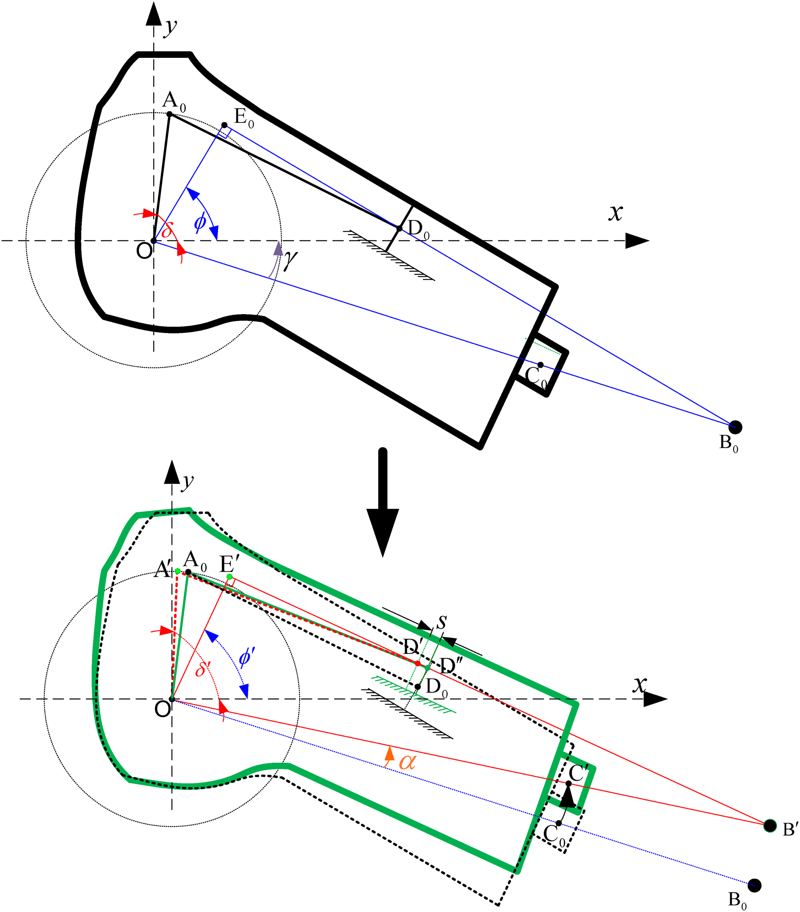
Once OC rotates by an angle of α counterclockwise around O, point C moves from C0 to C′, while E and D move from E0 to E′ and from D0 to D′, respectively. Since point A does not move, we have: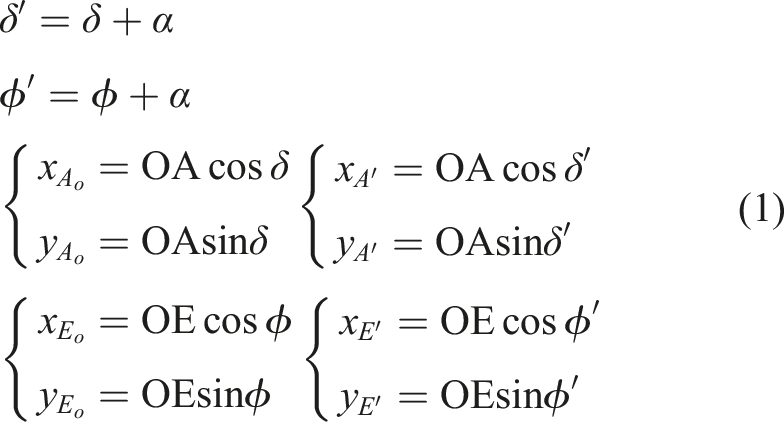
To calculate the gas compressions within spring actuating cylinder, coordinates of piston rod end before and after compression, i.e., 
The equation for the straight line passing E′ point perpendicular to OE′ (i.e,. E′B′) is,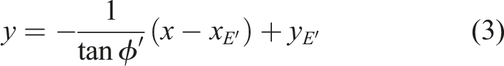
Further introduce equation (3) to equation (2), we have,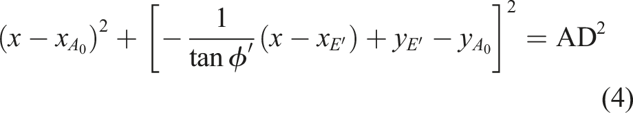
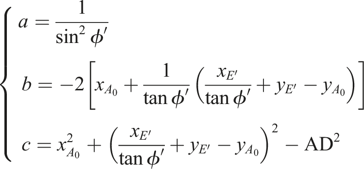
Hence, the coordinate of D″ could be obtained,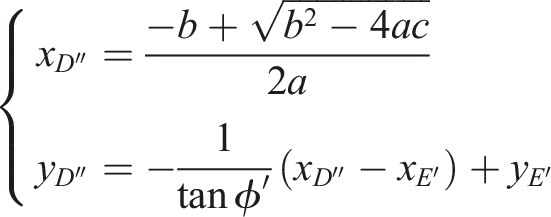
Similarly, the coordinate 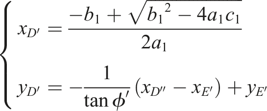
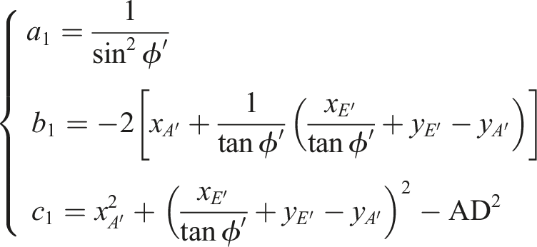
With coordinates of 
Once α is changed, the amount of gas spring compression s is also changed. Let
Then, the tracking of the actuating cylinder piston rod end Trajectory of actuating cylinder piston rod end D with and without gas spring compression.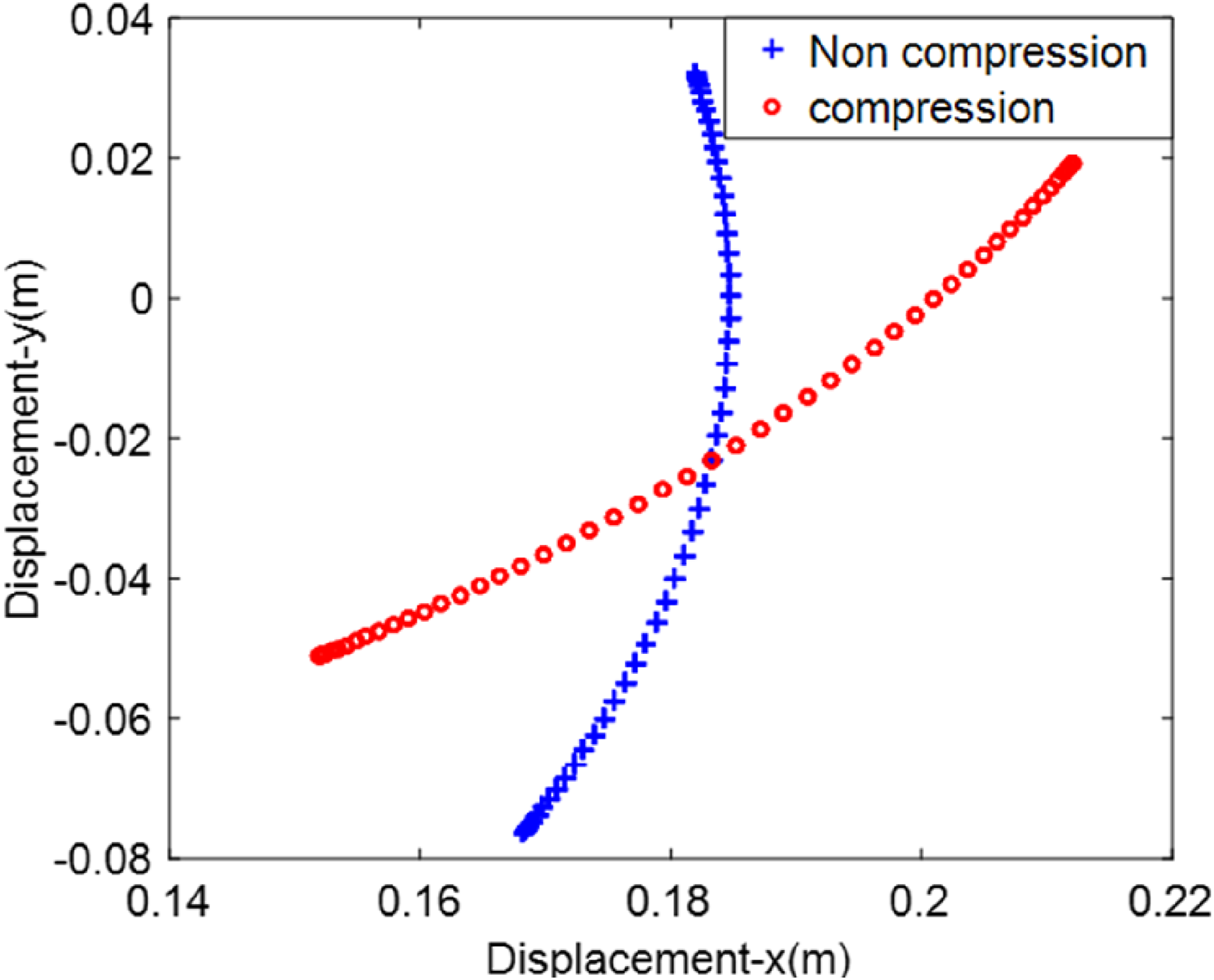
Composition and kinematics analysis of oil and gas spring
When ignoring the compressibility of the oil, the characteristic model for hydro-pneumatic spring is shown in Figure 4, wherein the gas is compressed downward by external force. In short-term dynamic response analysis, oil-gas springs typically have excellent sealing structures, such as the use of high-performance sealing rings and guide sleeves, which can effectively prevent gas leakage. Under normal operating conditions, the leakage rate of oil-gas springs is usually much lower than the rate of gas pressure change. Therefore, within a short time scale, the impact of gas leakage on the overall performance of the system can be disregarded. Additionally, the gases filled in oil-gas springs are mostly nitrogen or other inert gases, which have the advantages of high molecular stability, inert chemical properties, and low reactivity with hydraulic oil or metal materials. Nitrogen, within common working temperatures (such as −40°C to 80°C) and pressure ranges (for example, 10 MPa to 30 MPa), has a compressibility coefficient close to the expected value of an ideal gas, with relatively minor deviations from the ideal gas state. Assume P0 and V0 to be the initial gas pressure and volume, respectively. If the pressure and volume of the chamber change by Characteristic model for hydro-pneumatic spring.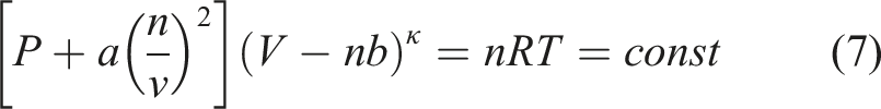
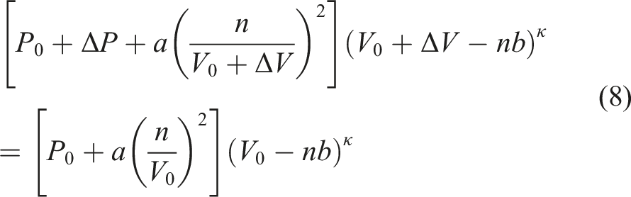
Rewrite equation (8) to obtain 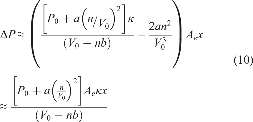
Hence, the amount of gaseous can be approximated as below,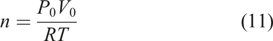
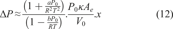
Replace 
Since A
e
does not change with x, it follows that 
For a fretting hydro-pneumatic spring, its elastic coefficient does not changed near the initial position. Assume that 
Damper components and kinematics analysis
Figure 5 presents both a sketch and the 3D internal structure of the damper within the designed ISU. This structure modifies the axis joint of the balance elbow by placing the damper inside, so that it is connected coaxially with the axis of the balance elbow through splines. As shown in Figure 5(a), the damper consists mainly of a servo valve, a fixed throttle orifice, a diaphragm, an outer wall, a rotating blade, a pressure-limiting valve, and a pressure equalizer. The rotating blade and diaphragm divide the entire workspace into four parts: C1, C2, C3, and C4, as shown in Figure 5(a). The balance elbow swings up and down to drive the rotating blade within the shock absorber cavity, causing cavities C1 and C3 or C2 and C4 to become high-pressure chambers, while cavities C2 and C4 or C1 and C3 become low-pressure ones. The oil flows from the high-pressure cavities through the fixed orifice and servo valve to the low-pressure ones. The servo valve, spanning both sides of the isolator, adjusts the valve opening and flow volume within the damper throttle channel to modulate the damping forces and ultimately achieve the semi-active damping effect. It is worth noting that the controllable damping force is adjusted here, while the damping effect of the fixed throttle orifice remains unchanged. Two pressure-limiting valves fixed on the blade are used to prevent the blade shaft from being damaged by excessive pressure within the shock absorber chamber. (a) Structure of the damper, (b) decomposing of the damper.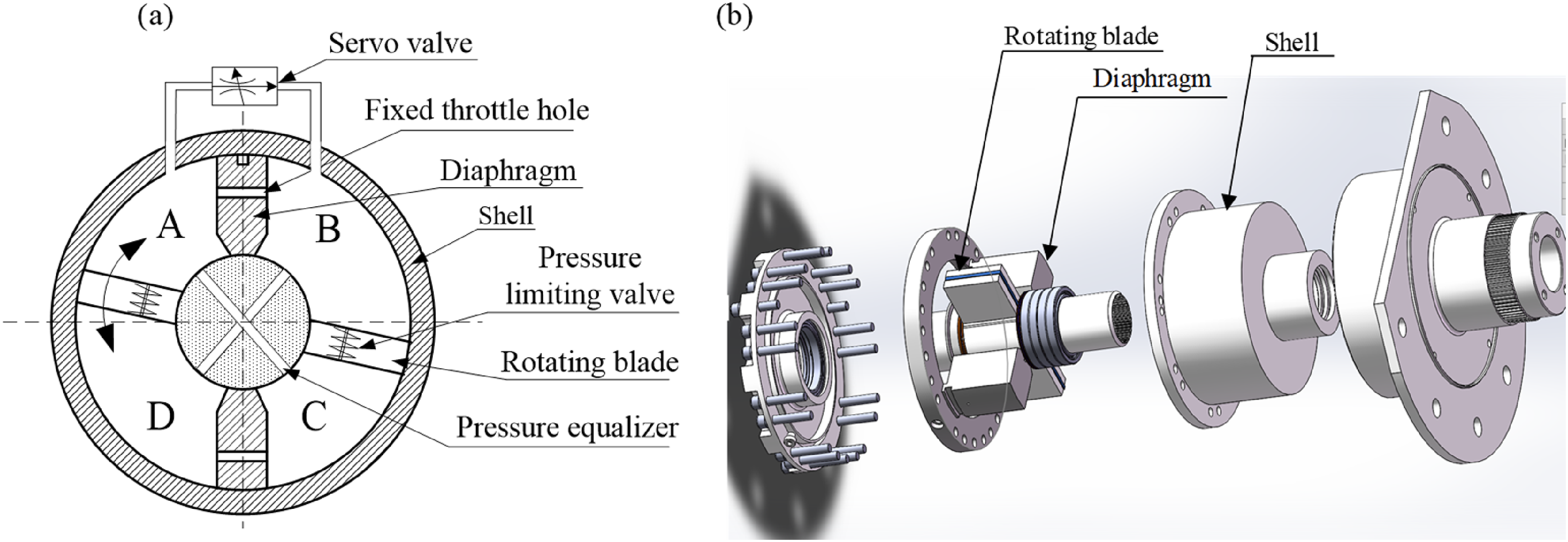
Assuming that the pressure distribution on the blade surface is uniform, the relatively low rotational angular velocity and the oscillation near the equilibrium position, the system is simplified according to the law of conservation of energy, geometric transformation and fluid dynamics equivalence. As demonstrated by Zhao
14
in their study on rotational hydraulic dampers. The rotating structure of the vane damper is converted to an equivalent linear structure as shown in Figure 6. Once the vane rotates, the pressures within the two cavities connected by the pressure equalizer channels are equal, while both the oil temperature and oil bulk elastic modulus remain constant. Therefore, the leakage inside the damper is considered laminar flow. The wheel axle C is affected by road conditions and may generate a disturbance x
u
, which thus causes a disturbance displacement x
s
and an acceleration a at the vehicle gravity center, affecting the vehicle ride comfort. Equivalent linear structure of vane damper.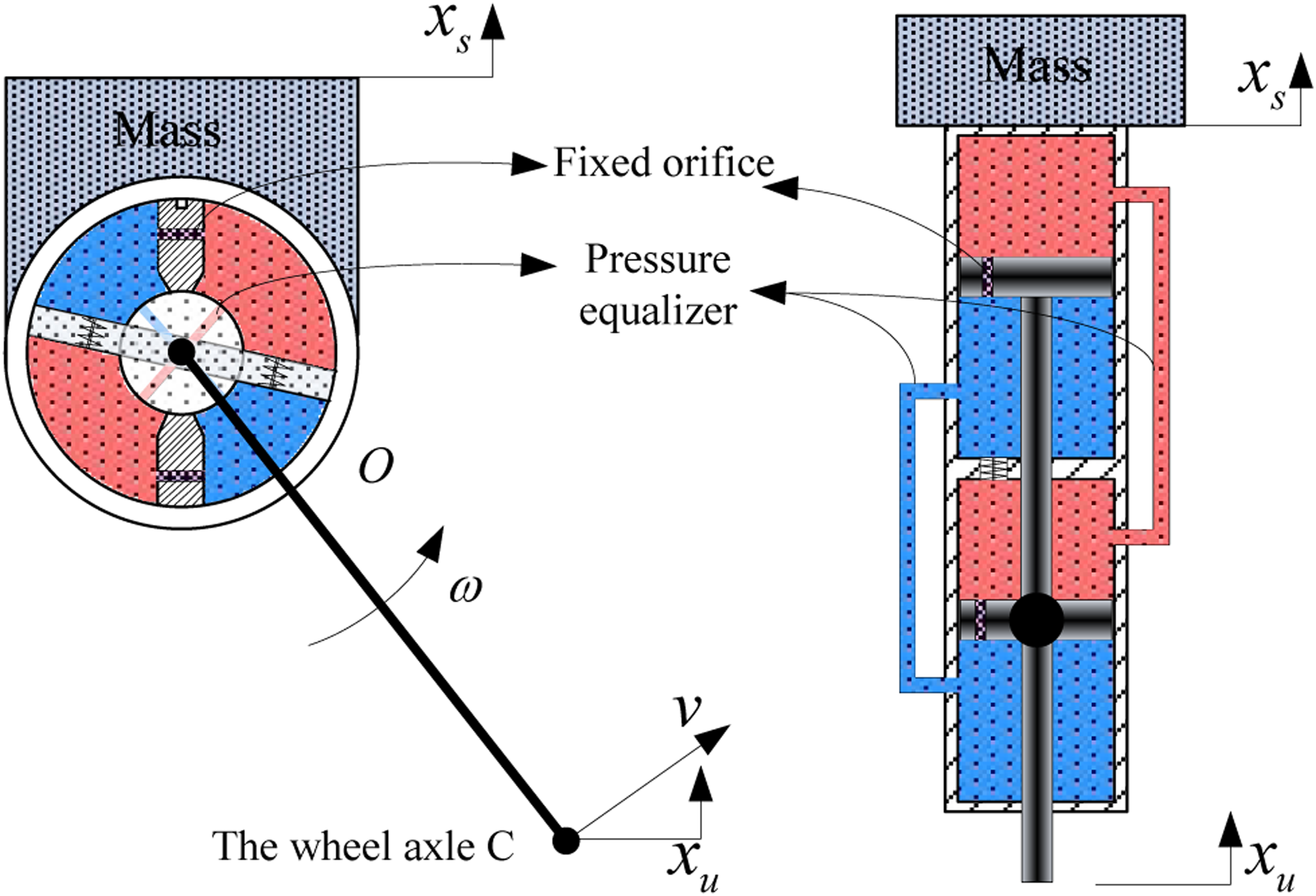
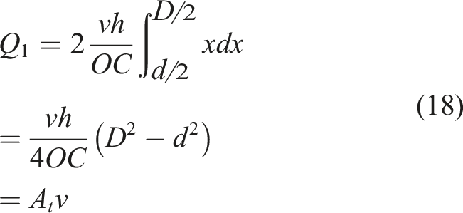
By utilizing the flow continuity equation,
15
one can obtain the flow rate of the blade damper as follows,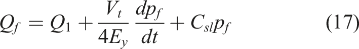
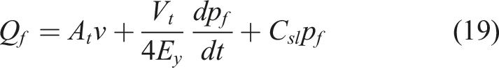
Hence, the damping force experienced by the balance elbow at C could be obtained as follows according to the moment balance principle,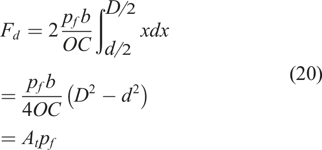
Mathematical model for suspension system
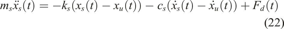
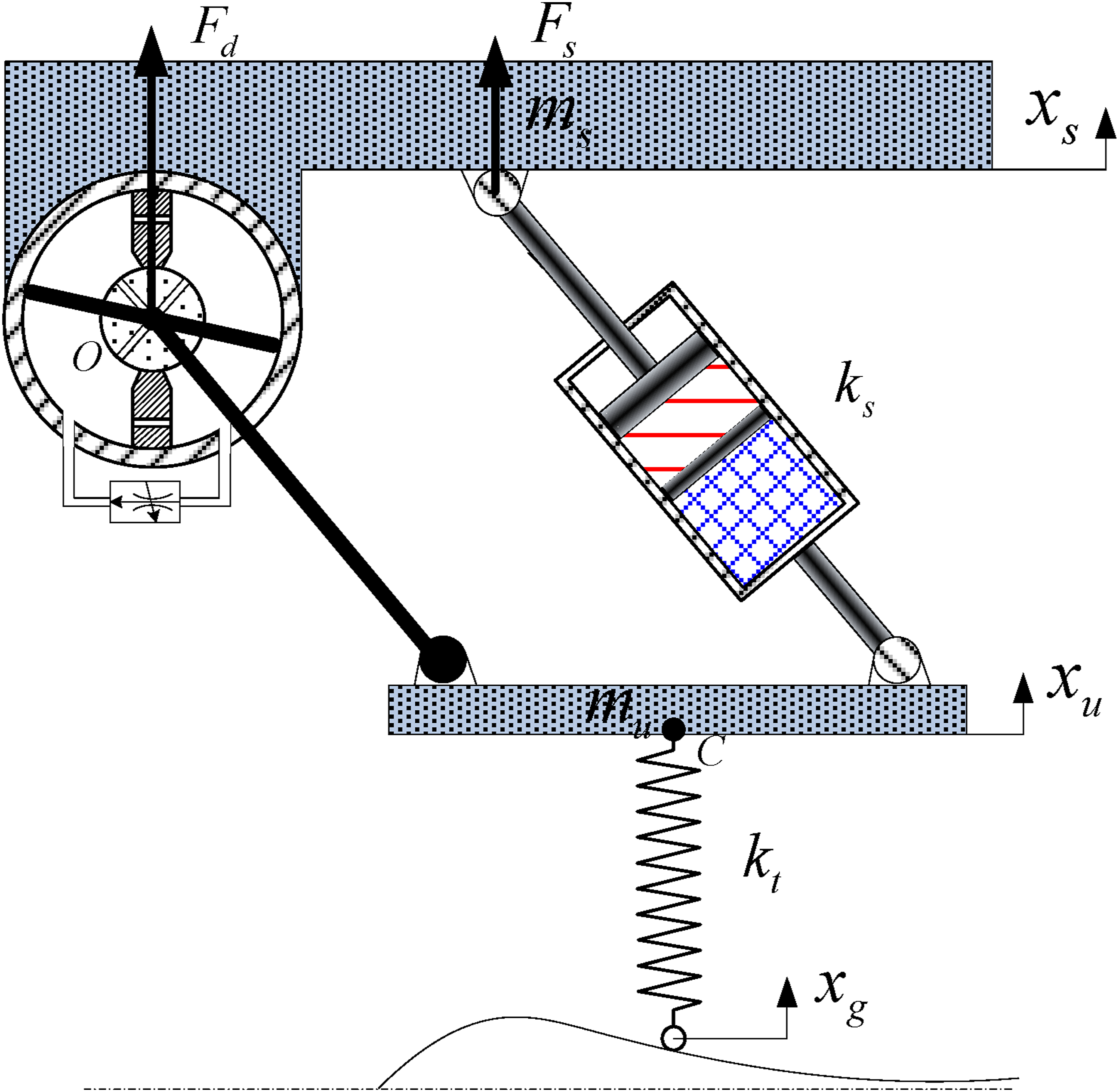
The Kinematics of the elbow-mounted hydro-pneumatic suspension system as shown in Figure 7 can be described using the following equations, Single wheel suspension system structure model of a tank.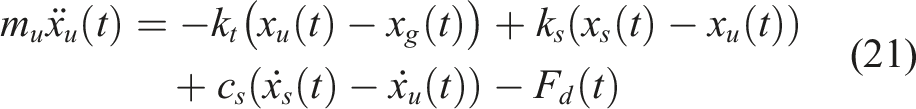

Applying Laplace transform to equations (21)–(23) and select the following state variables,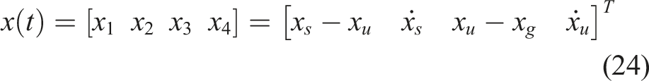
Then, the Kinetic equations can be rewritten as follows: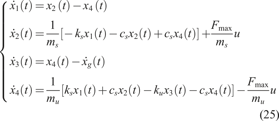
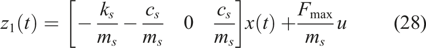
The primary objective of suspension system control is to reduce the amplitude of vertical acceleration of the vehicle body within a specified frequency range. During this process, vehicle road contact must be maintained by an appropriate dynamic-to-static load ratio, and the constraint can be expressed as follows,

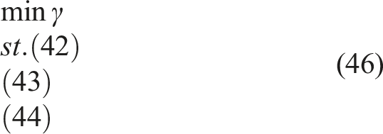
LMI based performance optimization for
/generalized
output feedback
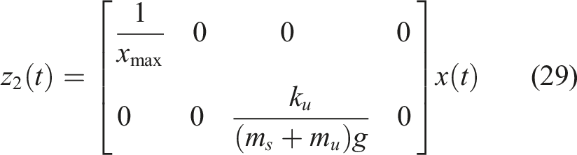
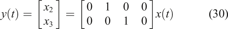
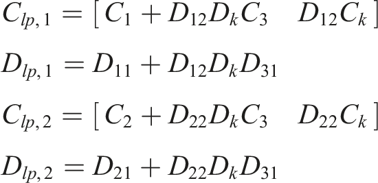
The elbow mounted suspension is a linear time-invariant system, and its normalized state-space equations could be described as below according to the system model,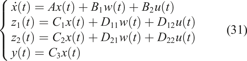
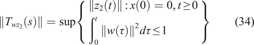
The main objective is to design a compression controller such that the following constraints could be satisfied,

When the output feedback controller expressed as below is connected to the system expressed by equation (31),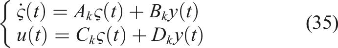
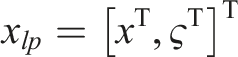
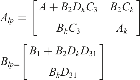
Then the state-space equations of augmented system could be expressed as follows,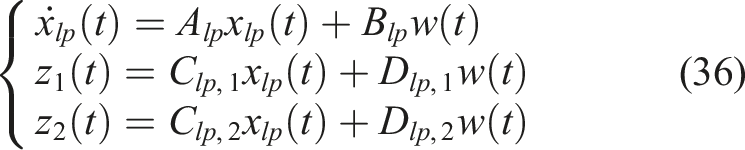
The LMI approach is adopted to optimize the controller design for the close-loop augmented system, such that the physical constraint could be satisfied in different cases.
For 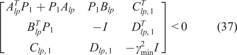
For Generalized H2 performance: there should exist a symmetric positive definite matrix P2 satisfying the following constraints
17
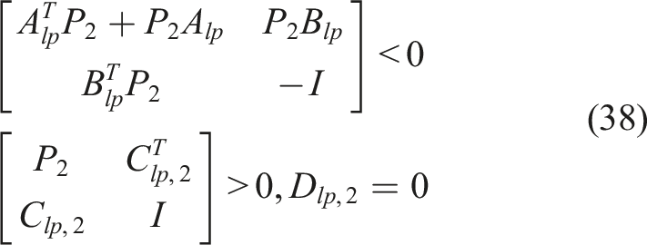
For Pole assignment: the poles of the closed-loop system should fall in the LMI region
18

Such a LMI optimization problem could be solved only there exists a symmetric positive definitive matrix P3 satisfying,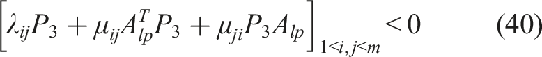
Therefore, to solve such a non-convex optimization problem, one needs to find a Lyapunov matrix P: = P1 = P2 = P3 to meet the above three constraints simultaneously.
19
When rewrite P into P = F2F1−1, and let,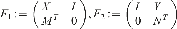
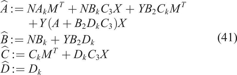
Specifically, since 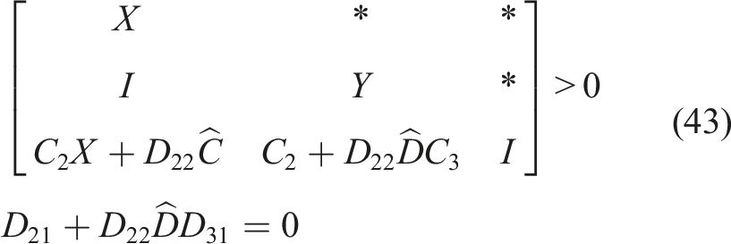
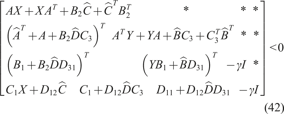
Once multiply a F1T and a F1 at the left and right hand side of InEq. (40), it could be converted to be an inequality as follows20,21: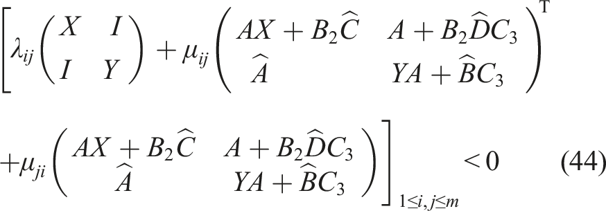
Therefore, for an elbow mounted suspension system described by equation (31), only when there exist a set of solutions
Simulation and experiment
Simulation results
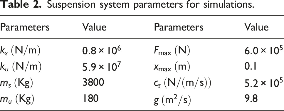
Suspension system parameters for simulations.
The poles of the closed-loop system should be located within the LMI region to ensure the stability and dynamic performance of the system. This LMI region is defined by linear matrix inequalities, which limit the positions of the poles in the complex plane, ensuring that all closed-loop poles are in the left half-plane and meet a certain decay rate, thus preventing the system response from diverging and achieving stable operation. At the same time, the distance of the poles from the imaginary axis determines the response speed of the system. The farther the poles are from the imaginary axis, the faster the dynamic response of the system, which can more effectively suppress road disturbances and improve the performance of the suspension system. In addition, the LMI region also regulates the damping characteristics of the system by restricting the ratio of the real part to the imaginary part of the poles, avoiding excessive oscillation or hysteresis, and enhancing ride comfort and anti-interference ability. Choose LMI region to be the left half open complex plane, then the corresponding characteristic function could be expressed as below,
The typical vehicle ride-comfort verification method regulated in GB4970-1996
24
was adopted for vehicle testing in this study. Specifically, a single slope convex block with length of 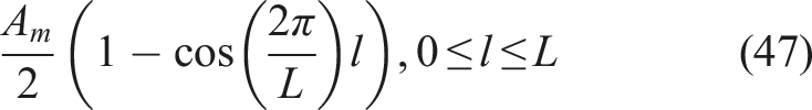
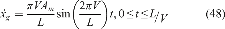
Since the common tank vehicle horizontal speed V is
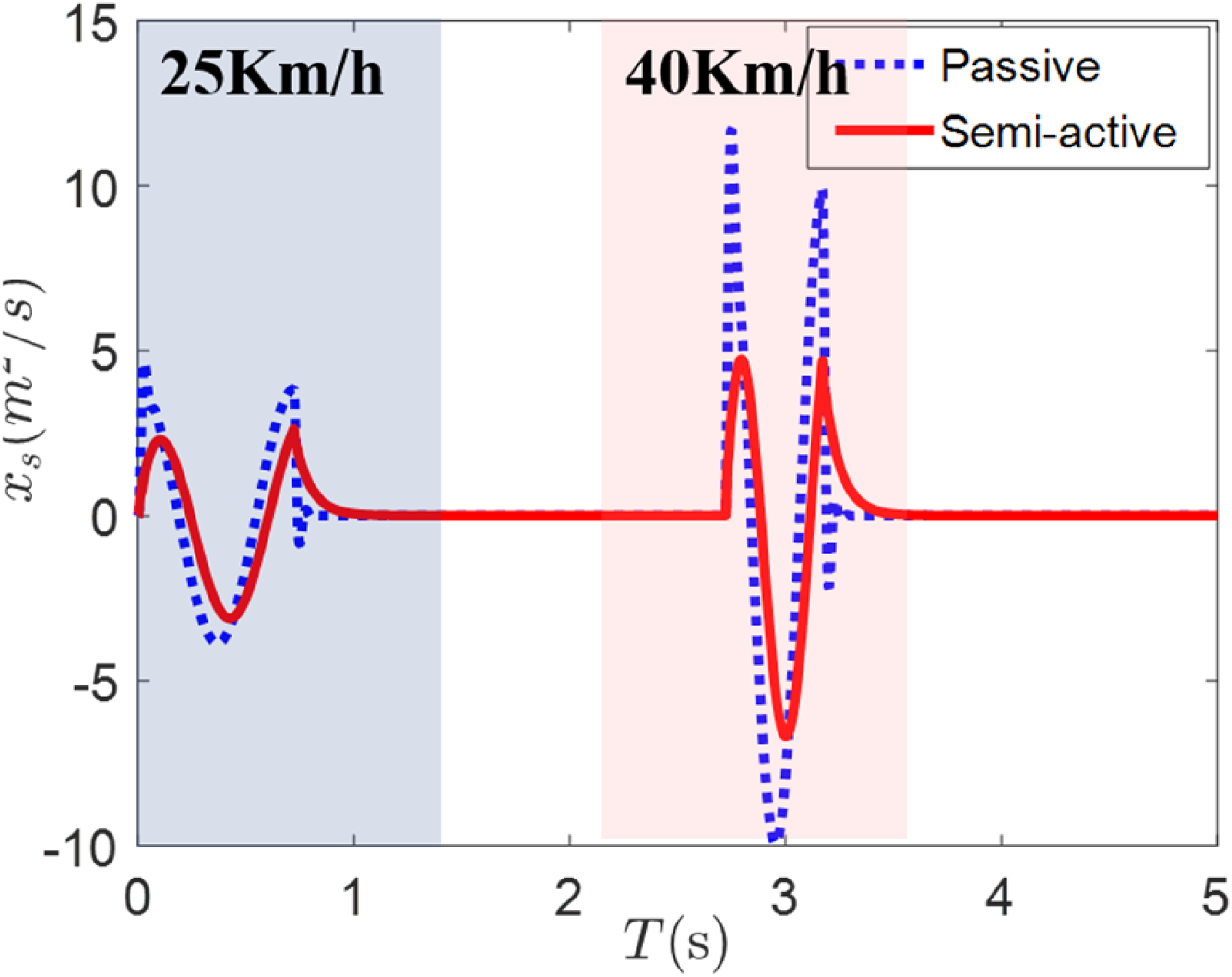
Figure 8 shows the closed-loop Bode diagram of Bode comparison of suspension system Comparison of vertical acceleration.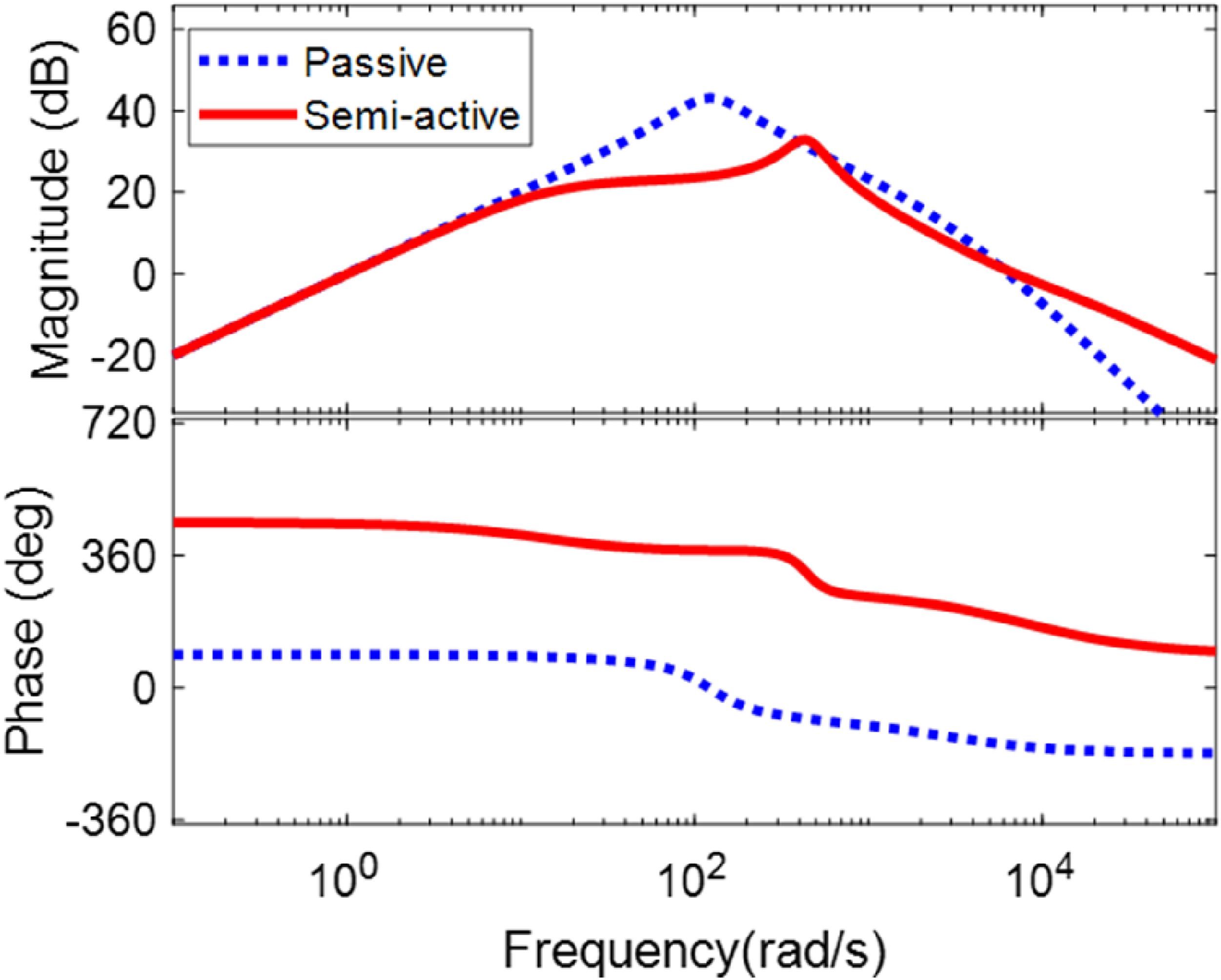
The spring and non-spring mass speed, i.e., Comparison of spring mass speed (a) and Comparison of non-spring mass speed (b). Comparison of suspension travel (a) and comparison of wheel compression (b). Comparison of suspension travel ratio (a) and comparison of dynamic and static load ratio (b).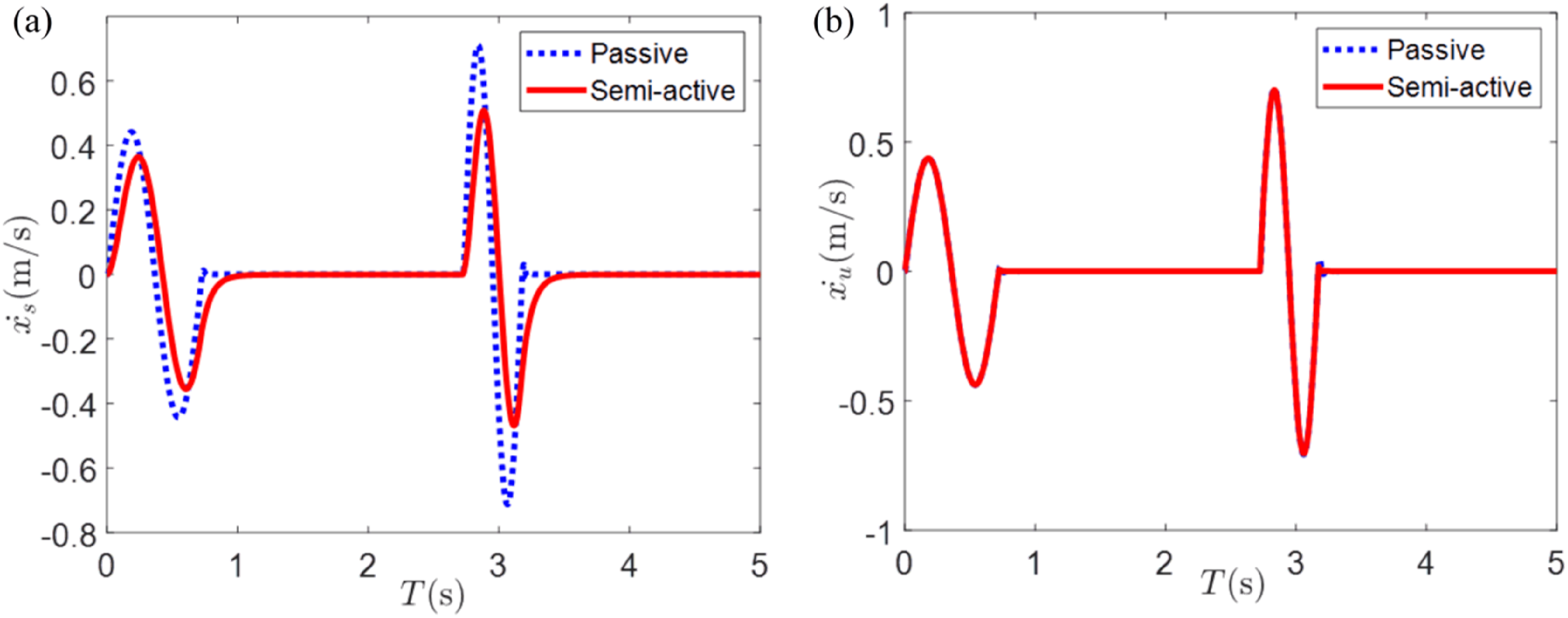
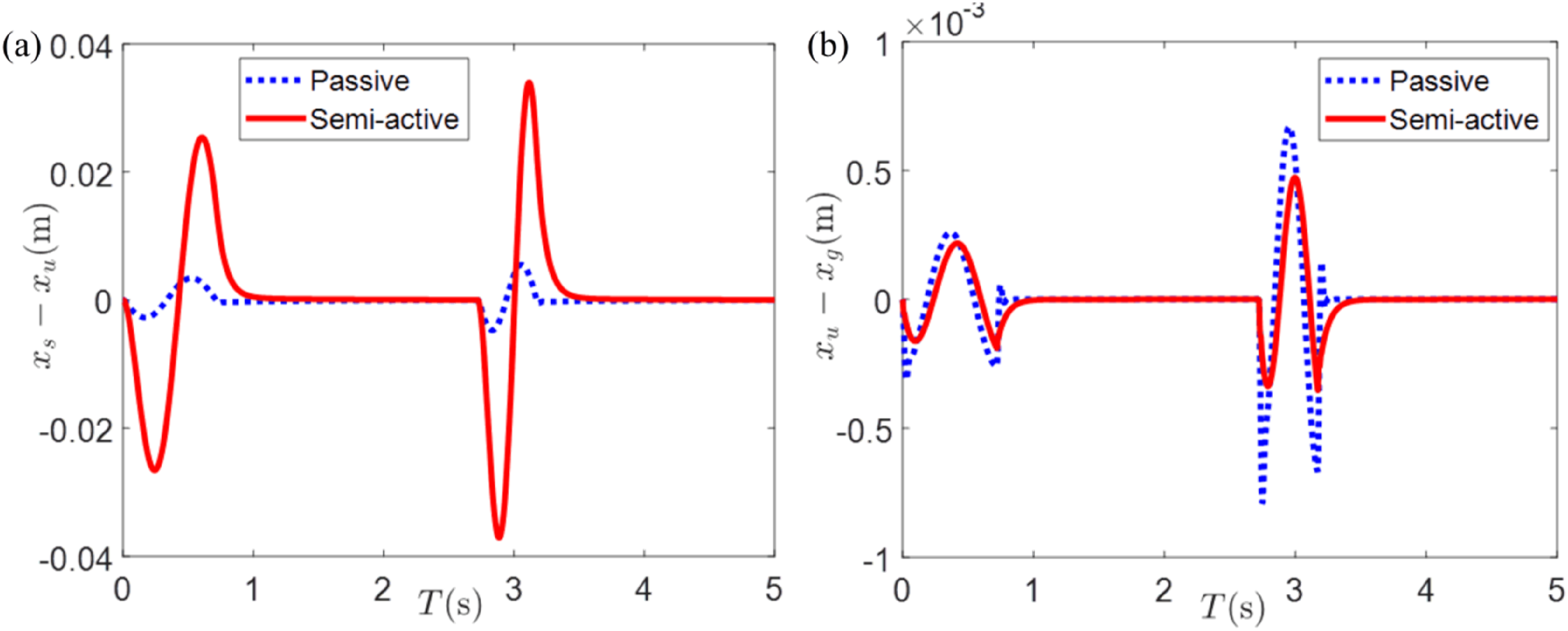
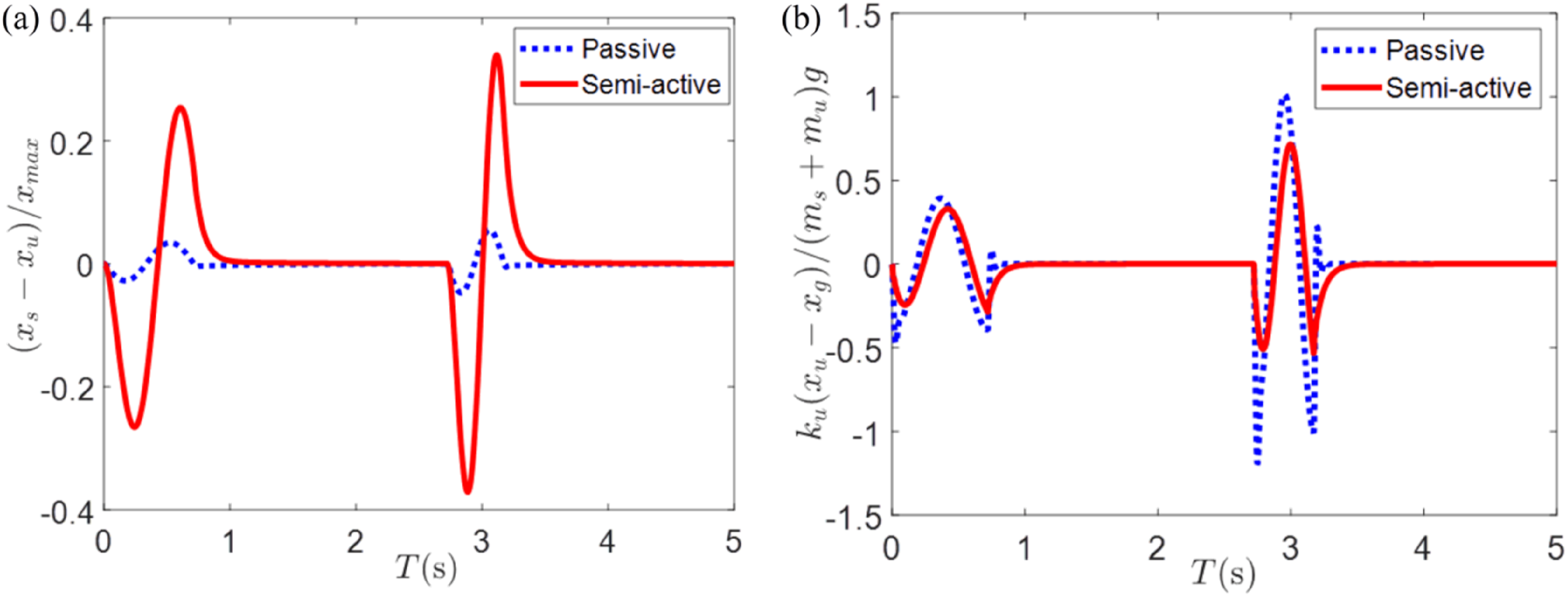
Figure 13 show the resultant force of the two systems acting on ms, wherein the red line is the elastic force, the blue line is the damping force and the green line is the resultant forces. The resultant force impacts on ms, while the damping force of the system under the output feedback control has the opposite motion trend as compared with the elastic force, and therefore, is helpful to reduce both the resultant force acting on ms and the acceleration in the vertical direction of ms. Internal force composition of passive system (a) and internal force composition of output feedback control (b).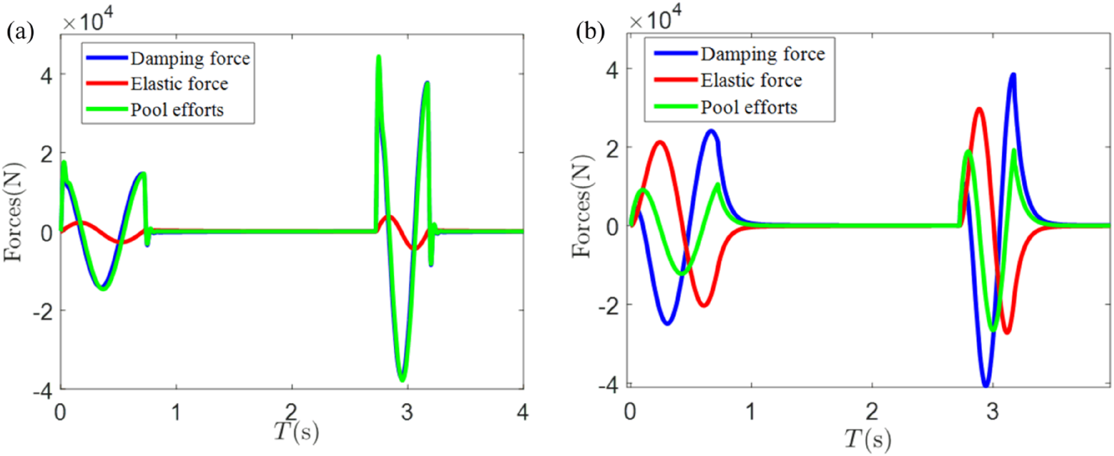
Finally, the damping force F
d
(t) can be obtained using equation (24), and thus, the adjustable damping hole of suspension can be controlled accordingly. The system poles could also be obtained, which are pole1: −8.9687 × 10⁶, pole2: −1.1535 × 10⁴, pole3: −3.7576 × 10³, pole4: −14.2790, pole5: −1.5379, pole6: −1.2174, pole7: −1.0719 × 10² + 4.2688 × 10²i, pole8: −1.0719 × 10²−4.2688 × 10²i. The distribution of those poles within the LMI region was shown in Figure 14. As seen, the negative dominant pole Pole6: −1.2174 enables the system to stay in an over damping state, making the system respond relatively slow to the disturbances. Poles distributed near the imaginary axis, the dominant pole is near the imaginary axis, and the response speed of the system is slow.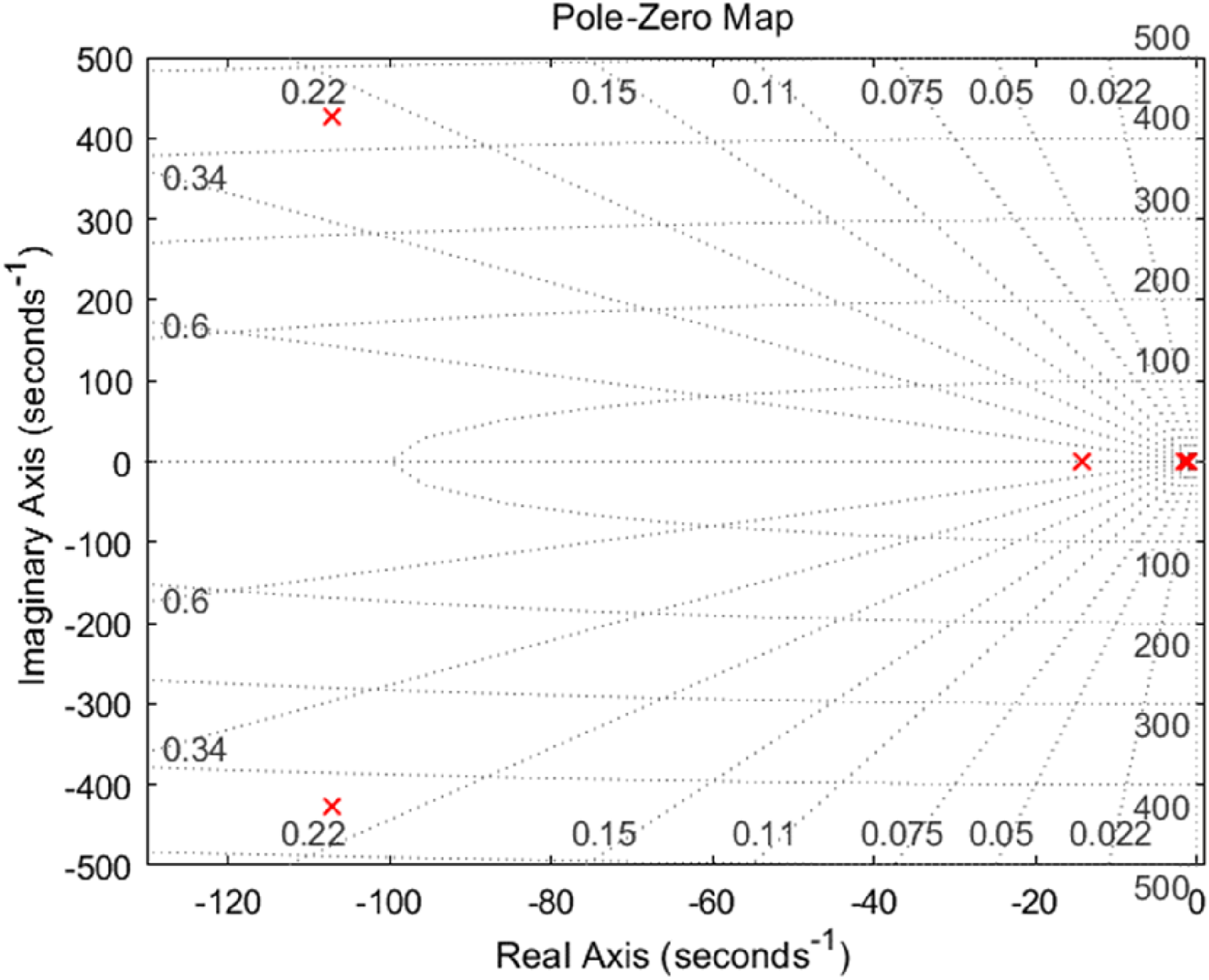
Experimental verifications
To verify the effectiveness of the controller to improve the tank ride comfort, experiments are conducted on a customized suspension testing platform in different cases. The test-bed is divided into two parts, excitation hydraulic loading unit, and suspension control unit. The vertical velocity of point C was produced by the load hydraulic cylinder and was used to simulate the disturbance w. The load spectrum of equation (48) was adopted with all parameters maintained. A force sensor was installed in between the loading cylinder and the tested suspension axle, which are fixed by connectors, while the suspension system is fixed onto the testing platform, as shown in Figure 15. The lab-built suspension system testing platform.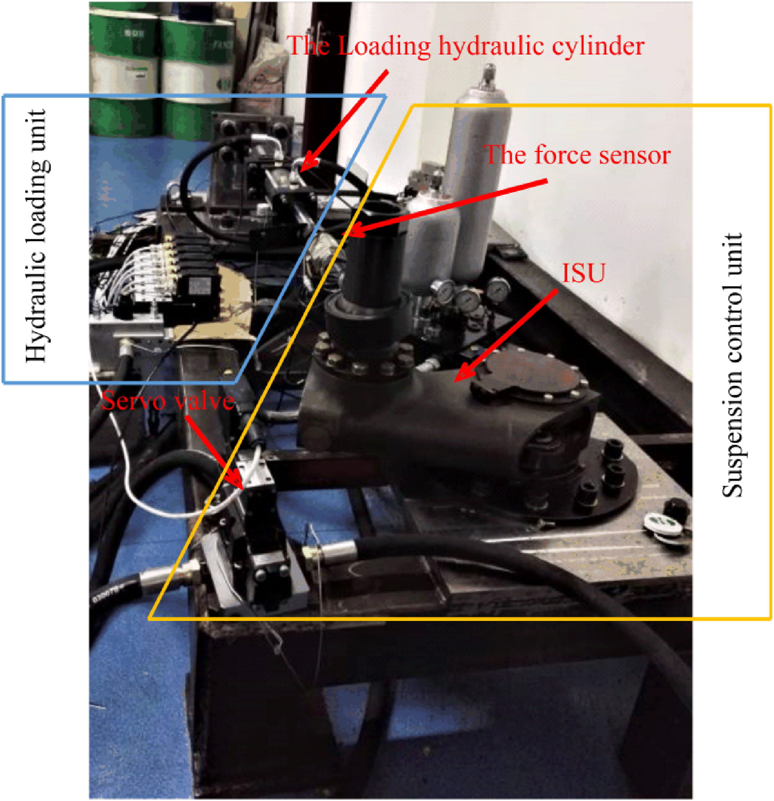
Sensor model and measurement range: In this experiment, a Kistler tri-axial force sensor is selected, with a full-scale range of ±100 kN and a resolution of 10 N. Accuracy and linearity: The manufacturer’s stated accuracy is 0.5%FS, with a linearity error of ≤0.1%FS. Calibration method: Before the experiment, the sensor was calibrated using a secondary standard calibration machine with three-point (20 kN, 50 kN, 80 kN) loading. The calibration curve was fitted using the least squares method. Zero drift was checked before and after each test, and the entire calibration was carried out at an ambient temperature of 25 ± 2°C. Suspension installation: The tested suspension assembly is fixed onto a rigid platform, with the force sensor placed between the loading cylinder and the suspension’s connecting end to measure the interaction force between the input excitation and the suspension.
Since the suspension system is fixed onto the platform, its real-time acceleration cannot be measured directly. However, if system parameters are kept unchanged and only the suspension damping changes, the acceleration ms will also change. Therefore, the effect of the system controller can be seen by measuring the interaction between the loading cylinder and the suspension. Two scenarios are selected: 1. The frequency of disturbance is fixed, and the force between the loading cylinder and the tested suspension shaft is measured at a single frequency. 2. Using chirp disturbance signal, measure the frequency response curve of disturbance channel in a certain frequency range, and observe the gain of disturbance channel.
Scenarios 1. During the test, the disturbance displacement of the road surface is 100 mm, and the velocity is 25 km/h. The disturbance displacement generated by the hydraulic cylinder is shown in Figure 16, wherein the blue line is the practical variation of disturbance displacement with time, and the red line is the disturbing displacement target trajectory. It can be seen that the real-time tracking from the blue line to the red line is satisfactory, which indicates that the displacement tracking is effective. Under the test disturbance, the force transducer signal can indirectly reflect the change of system damping. Disturbance displacement input.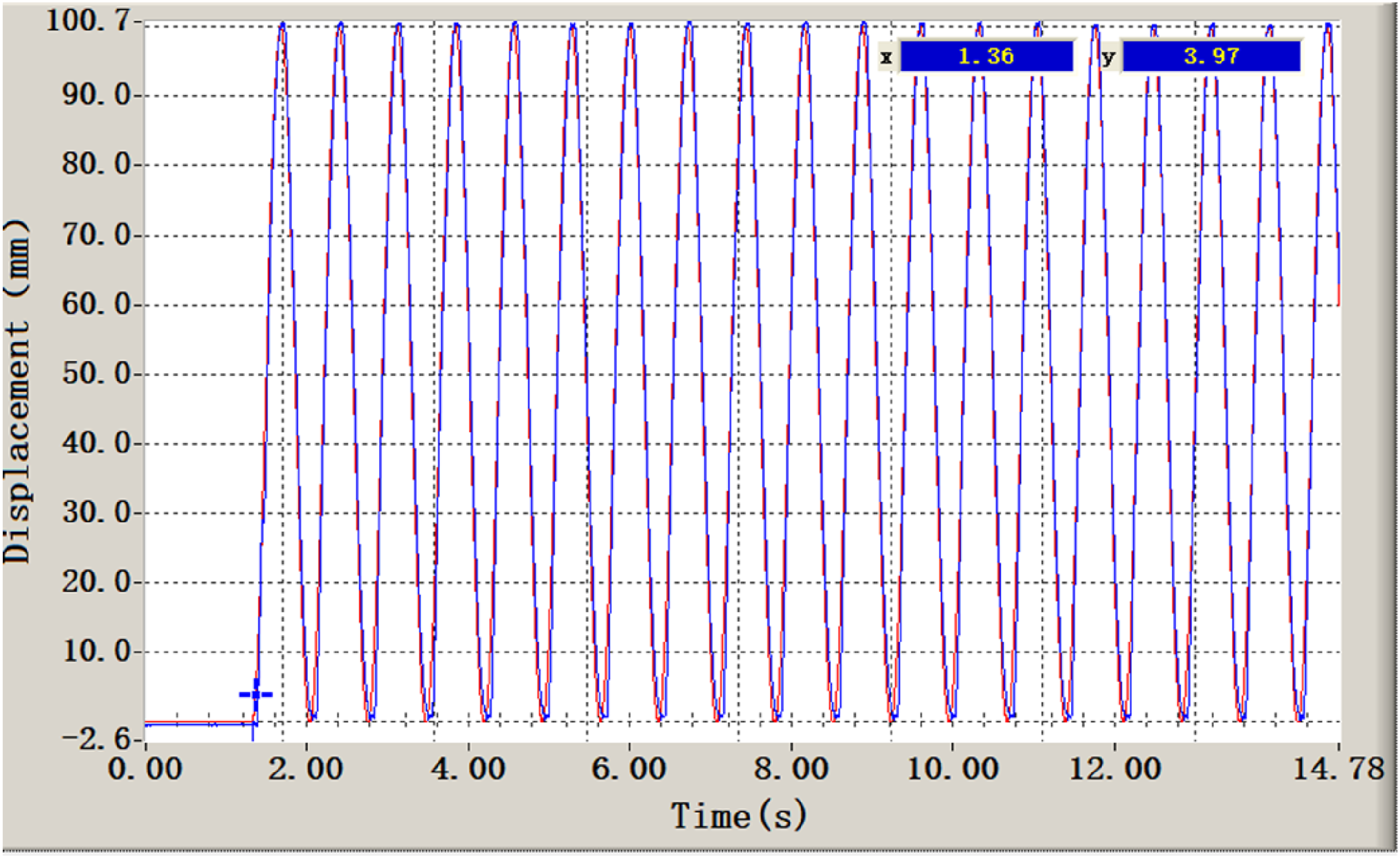
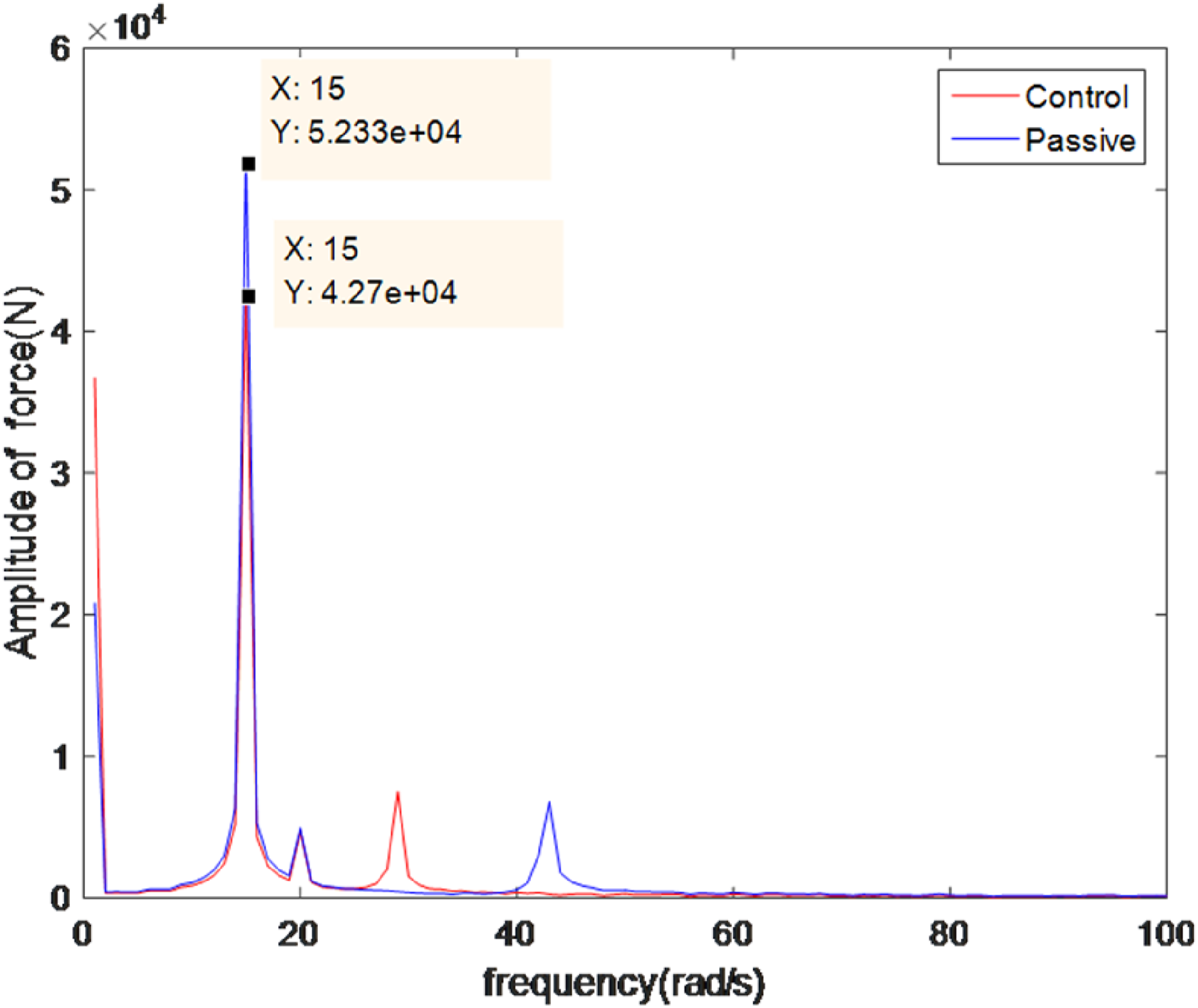
Figure 17 presents the force transducer signal, wherein the blue line is the interaction trajectory when only the fixed orifice is utilized, and the red line is the reaction trajectory of fixed orifice and servo valve utilized. As seen, when the vehicle goes uphill, the maximum interaction force after feedback control is smaller than that when the servo valve is closed, indicating that if the system elastic properties remain unchanged, the system damping capacity could be reduced, and thus, the system stiffness decreases. Such results prove that the ISU could help reduce the positive acceleration of the spring mass. On the contrary, when the vehicle is downhill, the maximum interaction is still smaller than that of the case when the servo valve is closed. FFT transform of force sensor signal is shown in Figure 18. As can be seen, when the output feedback control is applied, the amplitude of the force acting on the system near the disturbance frequency point is much smaller than that of the passive suspension. Such results demonstrate that with the LMI approach adopted, the damping force of the system could be reduced, which thus helps improve the suspension system damping performance. FFT transform of the force sensor signal changes. The blue line is force variation of suspension under passive condition. The red is that changes after optimization of system damping coefficient. FFT transform of the force sensor signal.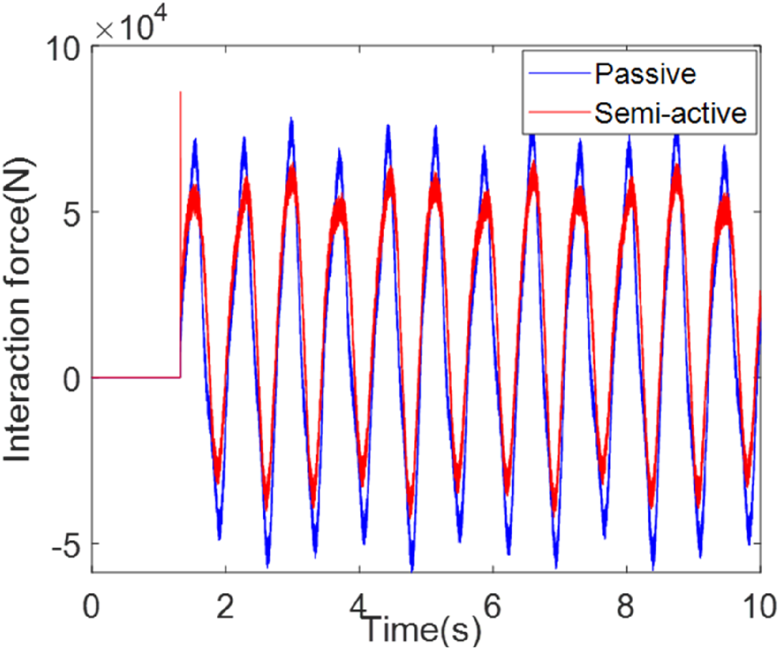
Scenarios 2. The chirp signal is sent out by the excitation loading system. Limited by the dynamic response of the loading system, the frequency band range is 0.1 Hz–2 Hz, the amplitude is 20 mm, and the duration is 204 s. Figure 19 shows the force sensor signal, in which the blue line is the interaction track when the only fixed orifice is used, the red line is the reaction track of the fixed orifice and servo valve utilized. Figure 20 is the amplitude-frequency curve of the disturbance channel. The existing chirp signal testing provides the frequency domain characteristics of the system over the entire operating frequency range, which is to some extent more comprehensive and representative than a single scenario. (a) Load location input, (b) the interaction force between the loading unit and the suspension. Amplitude-frequency curve of position input channel.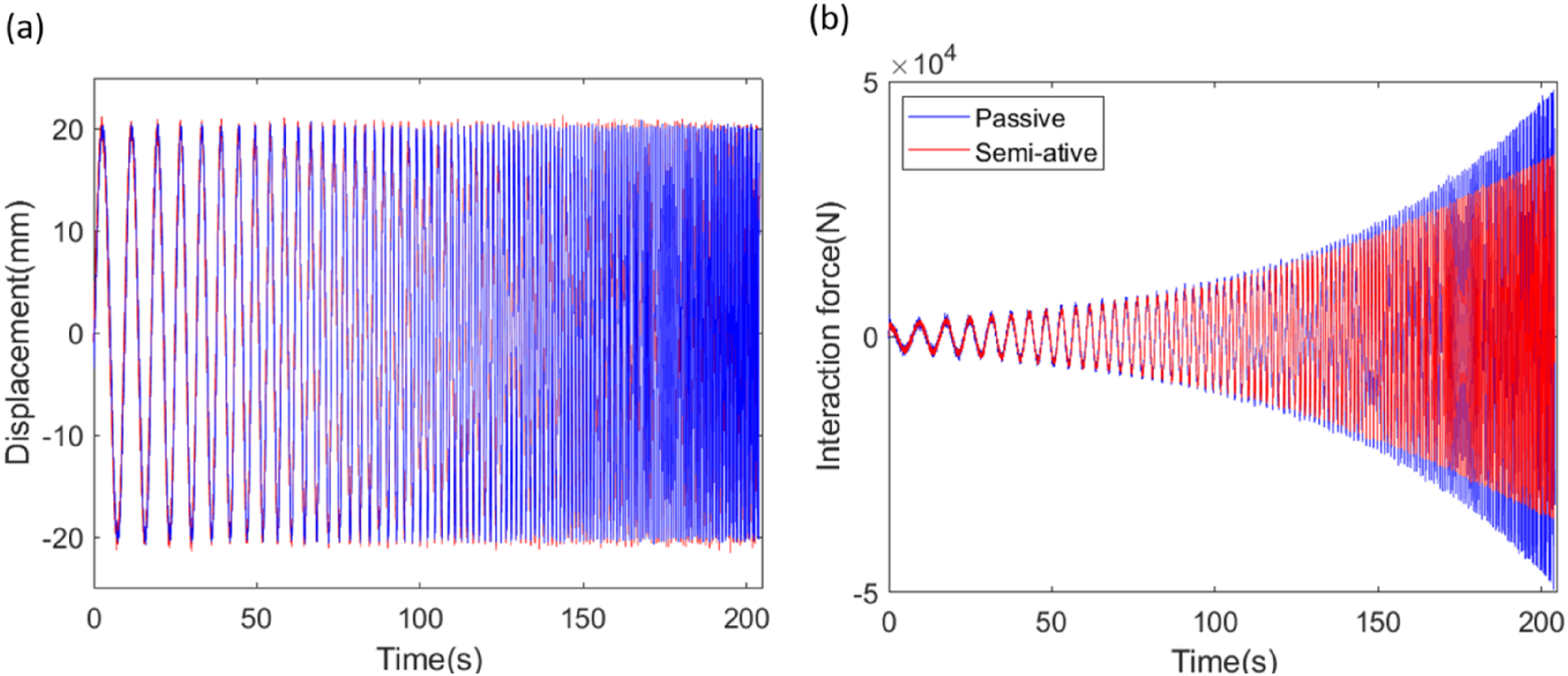
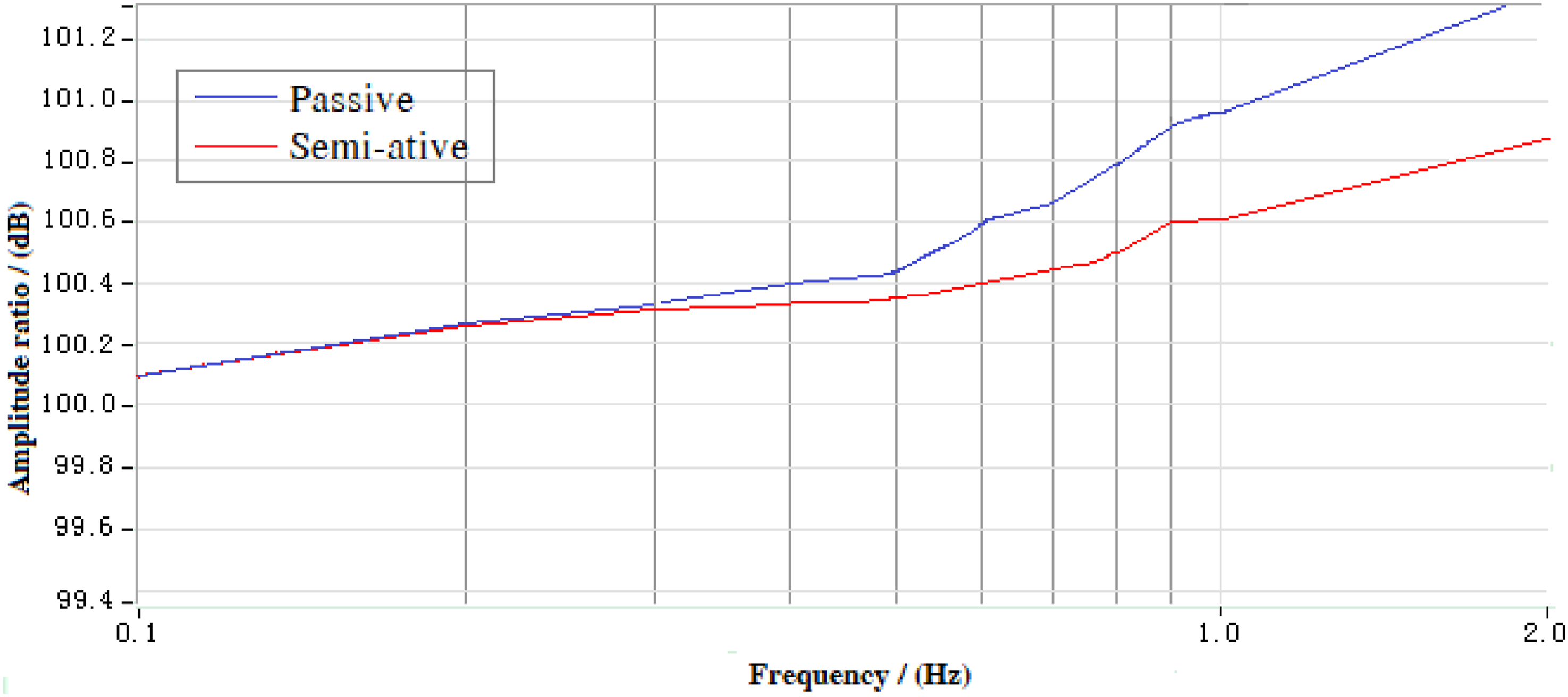
It can be seen that in the range of test frequency, with the increase of disturbance frequency, the interaction force between the excitation unit and suspension is increasing, and the gain of the disturbance channel is increasing gradually. However, the increase of gain of semiactive control is smaller than that of passive suspension, which can help to reduce the vertical acceleration of vehicles in the normal operating frequency range.
Analysis and comparison
Comparison of suspension control systems.
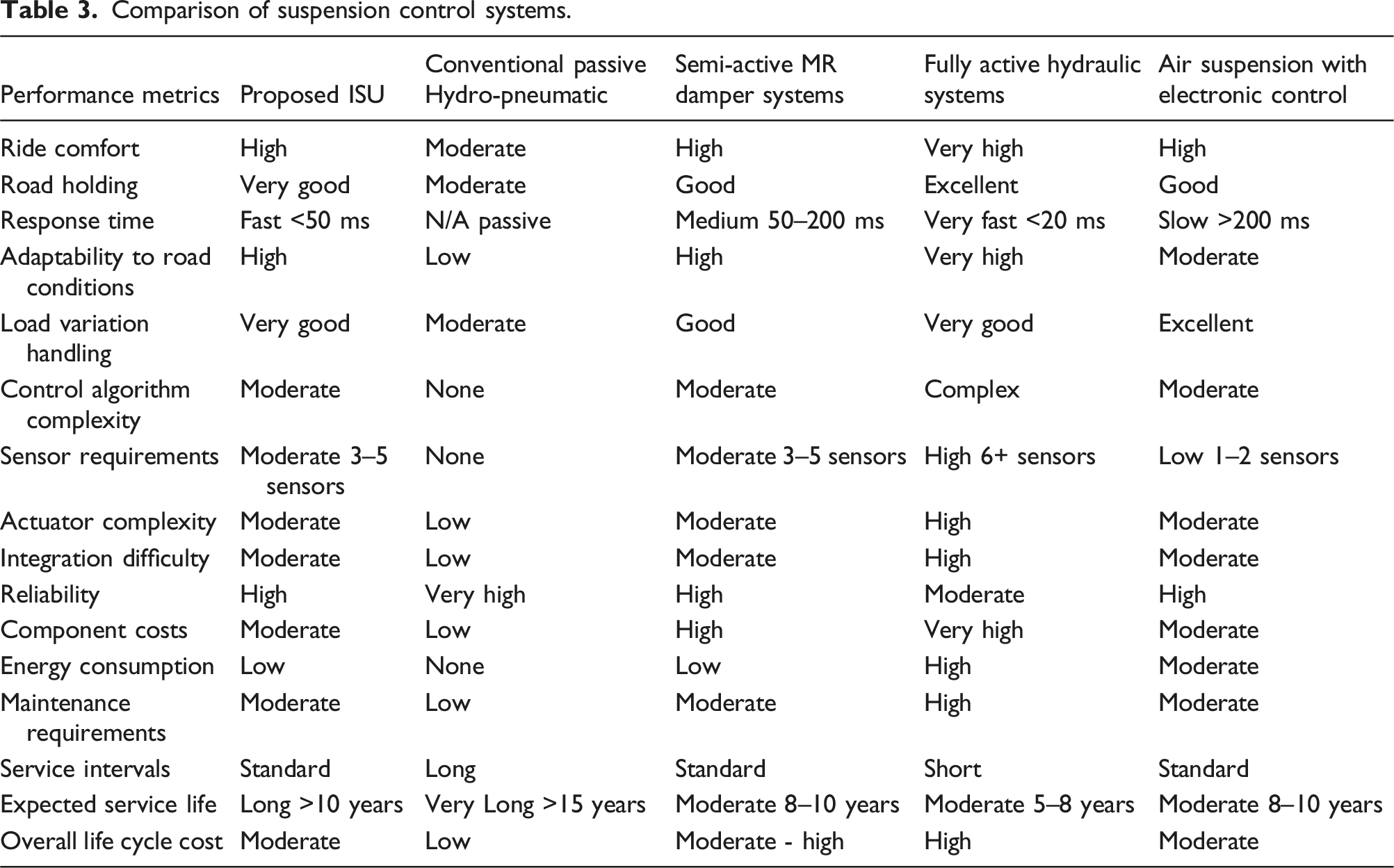
Based on the comparative analysis, our proposed in-arm hydro-pneumatic suspension control system offers the following distinct advantages: 1) Achieves performance comparable to fully active systems but with significantly lower complexity and energy requirements. 2) Incorporates fail-safe mechanisms that allow graceful degradation rather than complete failure. 3) Provides advanced control capabilities without the prohibitive costs associated with fully active systems. 4) Requires substantially less energy than fully active systems while delivering comparable ride comfort and handling improvements. 5) The ISU allows for space-efficient integration, particularly valuable for military tracked vehicles with space constraints.
Conclusion
This paper evaluates the feasibility of the ISU system in tanks for enhancing vehicle mobility and ride comfort. Based on a structural analysis of the semi-active suspension, the system kinematic model is established. Then, a multi-objective output-feedback controller is designed using an LMI-based optimization approach. Both simulations and experiments are performed to validate the effectiveness of the ISU and the LMI optimization for controller design. Results show that the LMI approach optimizes the maximum perturbation-channel gain across the entire frequency range, and the generalized H2 norm of the system remains below 1 when all physical constraints are enforced. Moreover, system performance can be further tuned by flexibly placing the closed-loop poles. These findings demonstrate that the proposed controller reduces the vertical acceleration, thereby improving ride comfort.
Footnotes
Author contributions
Investigation and Methodology, Sheng Dong; Software, Sheng Dong; Supervision and Validation, Sheng Dong; Writing – review and editing, Jiayu Liu, Shuaichao Quan and Shangpeng Guo.
Declaration of conflicting interests
The author(s) declared no potential conflicts of interest with respect to the research, authorship, and/or publication of this article.
Funding
The author(s) disclosed receipt of the following financial support for the research, authorship, and/or publication of this article: This work is supported by the Natural Science Basis Research Plan in Shaanxi Province of China (Program No. 2023-JC-QN-0659) and General Specialized Scientific Research Program of the Shaanxi Provincial Department of Education (Program 23JK0349).