
Abstract
Accurate prediction of nonlinear vibration behavior in rotor systems is essential for the safe and efficient operation of high-speed rotating machinery. This paper performs a nonlinear continuous rotor system (CRS) analysis. The CRS model is derived by including some important factors, like the gyroscopic effect, the rotary inertia of the disc and shaft, internal damping, large shaft deformation, and constraint to the axial motion of the shaft at the bearing ends. Unlike existing studies these effects considered independently, the proposed formulation captures their combined influence within a continuous model. The method of multiple scales is applied to obtain the autonomous amplitude and phase equations for simultaneous resonance conditions. A comparison of the analytical and numerical results yields a close match. Localized and nonlocalized oscillations are examined. Linear stability analysis is performed to assess the stability of steady-state solutions. Expressions for the critical value of a parameter along both directions are derived to determine the emergence of limit points (LPs). A comprehensive parametric analysis is conducted to investigate the impact of various system parameters on the system dynamics. The results demonstrate complex nonlinear behavior characterized by multivalued solutions, jump phenomena, and the onset of instability through limit point bifurcations. These findings provide critical insight into nonlinear rotor behavior, improving the understanding, design, and prediction of instability in systems operating under nonlinear and resonance conditions.
Introduction
A rotor is a primary component of machinery often used in various applications, such as compressors, motors, turbines, generators, and so on. Rotors are mainly used for power generation and transmission. The eccentricity between the center of mass and the geometric center is inevitable due to manufacturing defects, wear of rotors during operation, etc. The centrifugal force generated due to this eccentricity is the primary source of instability in a rotating system. The resulting vibrations of the rotor system may result in catastrophic failure, ultimately leading to unsafe working conditions and degradation of infrastructure and machinery. Minimizing the vibration in a rotating system is a challenging task. This may be accomplished at the primary phase of design. A better understanding of the effect of different parameters on the vibration characteristics of the system is essential in achieving a better design that can minimize the system vibrations.
A continuous rotor system model is developed to study the effect of different parameters on the nature of vibrations of a system. The geometric nonlinearities are small for small deflections of the shaft and are ignored in such cases. The shaft deflection may become significantly large under certain operating conditions, particularly near the resonance zone. This induces geometric nonlinearities and completely different system dynamics than the linear system. Restricting the shaft axial motion at the bearings may also cause nonlinearities in the system governing equations. This is also considered in the system model.
There are numerous literatures on the modeling and analyses of rotor systems. Some of the literature on modeling and analyses of non-linear rotor systems is discussed in this section. The rotor system models can be broadly categorized into: (i) discrete1–16 and (ii) continuous.17–36 Only the stiffness of the shaft is considered in a discrete system model, not its inertia. The dynamics of a rotor system in a discrete model are governed by a set of ordinary differential equations (ODEs). For a continuous rotor model, the dynamics of the system are governed by a set of partial differential equations (PDEs) with boundary conditions. In many cases, these PDEs with boundary conditions are reduced to a set of ODEs using different discretization methods for further analysis.
Some influencing factors considered in the literature for analyzing the dynamics of a discrete rotor system are as follows: shear effects, 1 large deformations, 1 Karman nonlinearity, 1 nonlinear curvature, 1 rotary inertia,1,16 external damping force,4–6,11,14,16 nonlinear restoring force,4,6,11 hydrodynamic force,4,15 unbalance mass,4,14 internal damping5,7 and gyroscopic effect.1,3,4,7,10,12,13,16 The impact of these factors on the discrete rotor system yields some interesting responses, such as forward whirling,3,6,10,12,16 backward whirling,2,3,6,10,12,16 multivalued solution,8,9,11,15 jump phenomenon6,8,9,11,15 and multiple loops. 15 Different resonance scenarios that may arise in a rotor system are (i) internal resonance,1,3 (ii) primary resonance,6,8,11 and (iii) simultaneous resonance.11,15
There is extensive literature on the analysis of continuous rotor systems.17–36 Hamilton’s17,31,32,35,38 and Lagrange’s18,23,26,38 equations mainly derive the governing partial differential equations and boundary conditions. The kinetic and potential energies of the rotor system are first determined to be employed in either Hamilton’s or Lagrange’s equations. Different discretization methods used to transform the PDEs into ODEs are the Galerkin17,32,35 method and the Rayleigh-ritz23,25 method. To solve or discretize the difficulties associated with complex rotor and continuous models, techniques such as the finite element method (FEM)10,31,34,38–43 and the variational asymptotic approach 32 are developed. A linear continuous system model with gyroscopic effect, the rotary inertia of disc and shaft, internal damping, large shaft deformation, and constraint to the axial motion of the shaft at the bearing ends. The derivation of the governing PDEs using Hamilton’s principle and the reduction of the PDEs into a set of ODEs using a Galerkin method is addressed.36,44–48
Some significant factors considered while analyzing a continuous rotor model include the nonlinear curvatures, 17 shear force,27,33 mass unbalance,18,25 gyroscopic effect,17,19,22,23,25,28,29,33,34,36,38 external damping,17,24 internal damping,20,21,32 dynamic axial force,25,27 large deformation in bending25,27,28 and rotary inertia.17,19,24,25,27,28,33,36 Continuous rotor systems exhibit similar behaviors to those seen in discrete rotor systems while performing the parametric analysis. They are the forward whirling,17,34 backward whirling,17,34 jump phenomenon,27–29 multivalued solution,27–29 periodic, 30 quasi-periodic, 30 subharmonic, 30 and chaotic motion, 30 etc. In this paper, the rotor system is modeled with factors such as gyroscopic effect, rotary inertia of disc and shaft, internal damping, large shaft deformation, and constraint to the axial motion of the shaft at the bearing ends. The bearings at support are regarded as linear springs. 36
Despite significant progress, several limitations remain in the existing literature. Most studies do not simultaneously account for the combined effects of gyroscopic moments, rotary inertia of both shaft and disc, internal damping, geometric nonlinearity due to large deformation, and axial constraints at the bearing supports within a combined continuous rotor framework. Furthermore, there is a lack of comprehensive analytical studies addressing simultaneous resonance conditions using perturbation techniques. The prediction of critical operating conditions leading to multivalued responses and limit point bifurcations is also not sufficiently explored. To address these gaps, the present study develops a nonlinear continuous rotor system model incorporating gyroscopic effects, rotary inertia, internal damping, large deformation, and axial constraints at the bearings. The governing equations are derived using an energy-based approach and reduced using appropriate discretization techniques. The method of multiple scales is employed to obtain amplitude and phase equations under simultaneous resonance conditions. A detailed stability and parametric analysis are performed to investigate the influence of system parameters on rotor dynamics. The study provides deeper insights into nonlinear phenomena such as jump behaviour, multivalued solutions, and system stability, thereby contributing to improved design and analysis of rotating machinery.
The rest of the paper is arranged as follows. Section 2 outlines the mathematical model. All the analytical methods for the nonlinear continuous rotor system under consideration are presented in Section 3. Amplitude and phase equations are derived using the method of multiple scales in Section 3.1. Linear stability analysis to determine the stability of the steady states is performed in Section 3.2. The expressions for finding the critical values of specific parameters corresponding to the initiation of muti-valued solutions are derived in Section 3.3. Following a discussion of all the findings in Section 4, Section 5 presents key conclusions.
Mathematical modeling
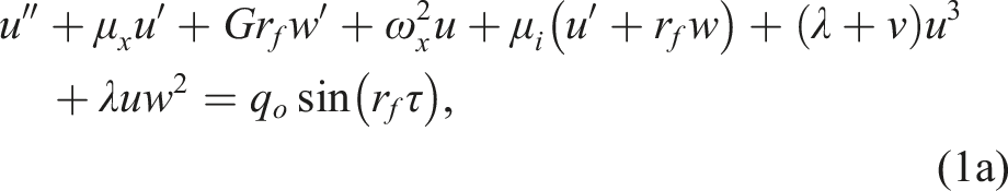
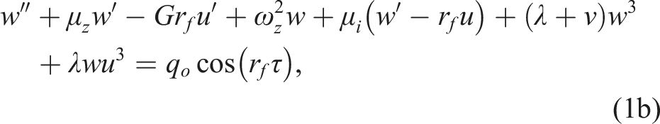
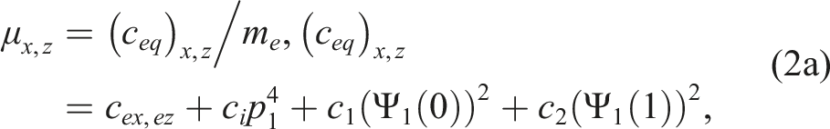
All the mathematical models of the rotor system are discussed in this section. The physical system shown schematically in Figure 1 consists of a rigid disc mounted on a flexible shaft supported by bearings ( Schematic representation of (a) disk rotating on a flexible shaft, (b) rotor eccentricity, (c) bearing 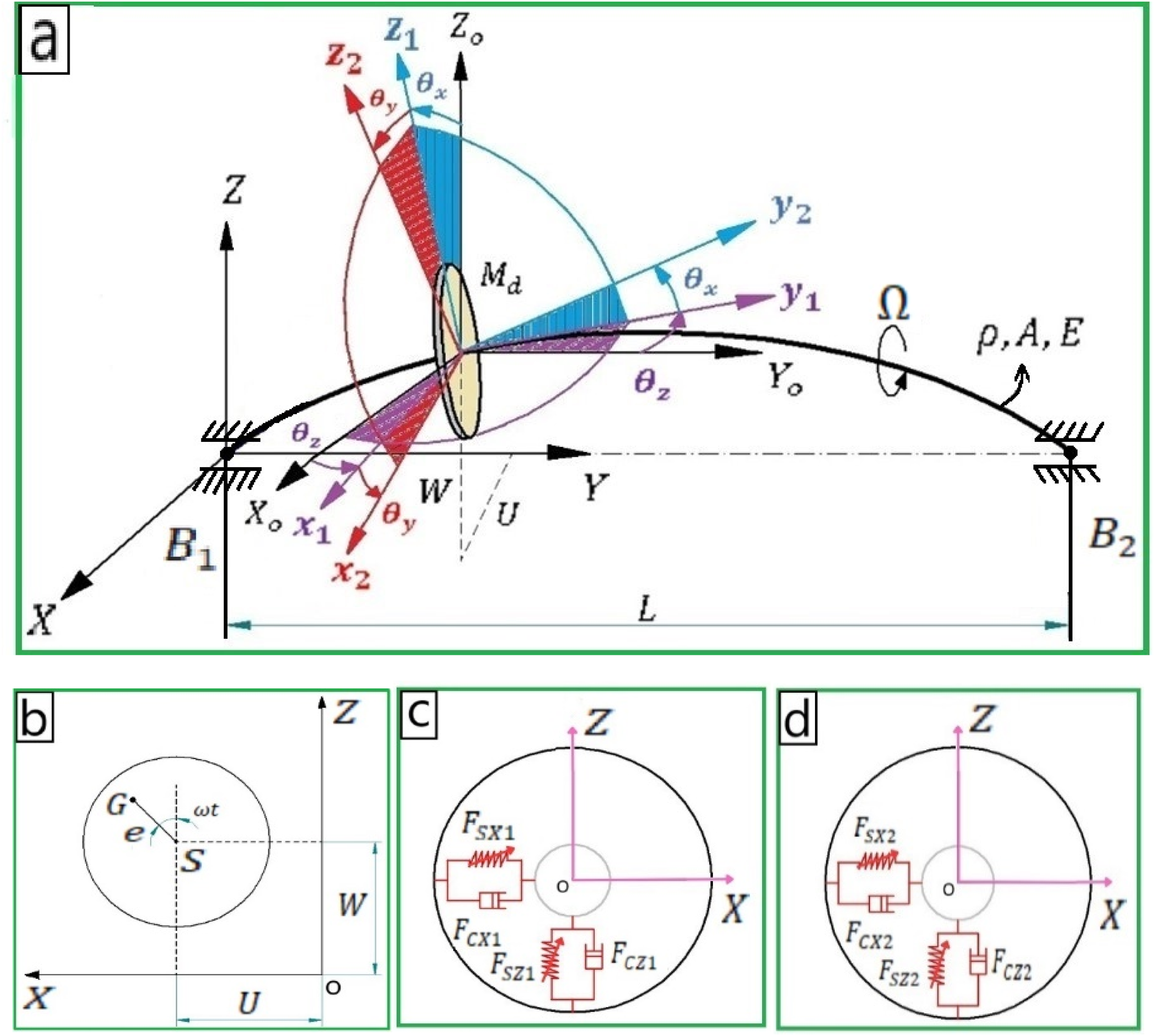
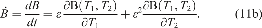
The ordinary differential equations (ODE) governing the motion of the continuous rotor36,44–48 in the horizontal and vertical directions are written as
Theoretical analysis is performed in the next section to obtain the expressions for determining the approximate values of amplitude and phase angle of oscillations at different excitation frequencies.
Theoretical analysis
In this section, all the equations necessary for properly analyzing the rotor system are attained. The autonomous amplitude and phase equations for the rotor system’s horizontal and vertical oscillations are first derived using the method of multiple scales [37] (MMS) in Section 3.1. The linear stability analysis is performed in Section 3.2 to determine the stability of the steady-state solutions. Finally, the expressions for critical values of parameters leading to the initiation of limit points are obtained in Section 3.3.
Method of multiple scales
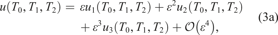
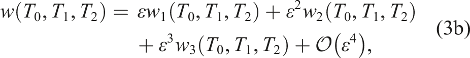
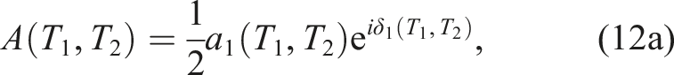
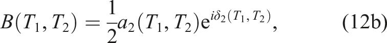
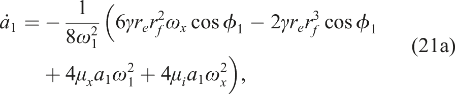
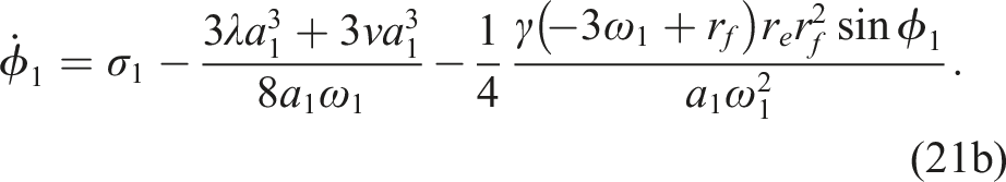
The method of multiple scales is employed in this section to derive the autonomous amplitude and phase equations for the vibrations of the rotor system along the horizontal and vertical directions. Initially, series solutions for the horizontal and vertical oscillations of the rotor system governed by equation (1a) and (1b), respectively, are assumed as
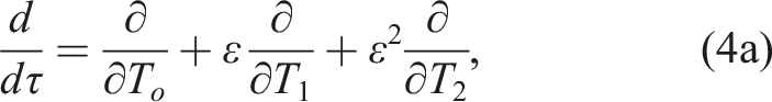
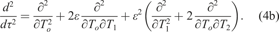
The system parameters are scaled as

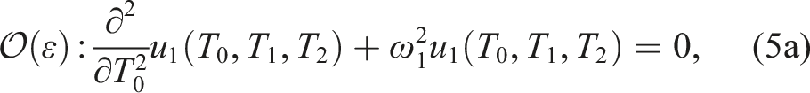
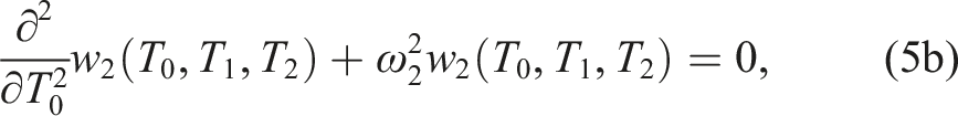
The solutions of equation (5) are assumed as


The simultaneous resonance

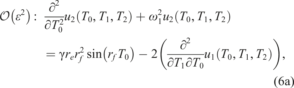
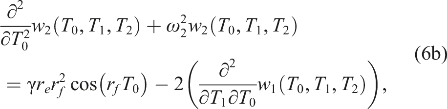
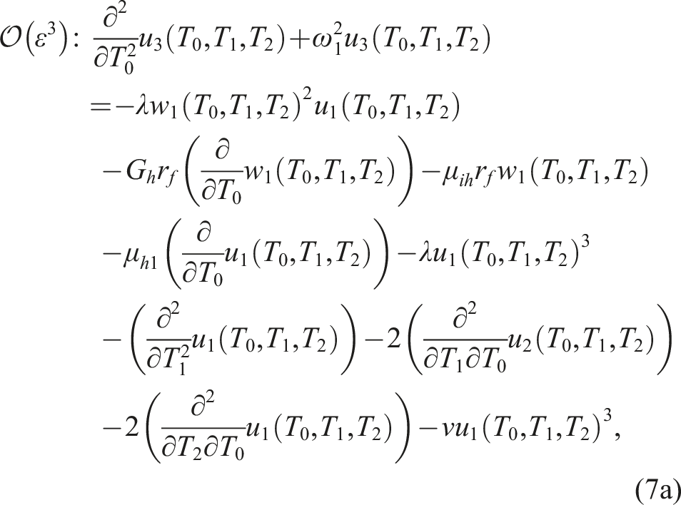
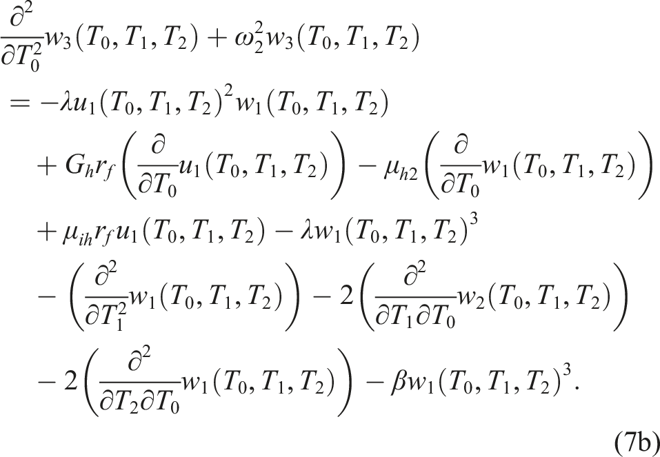
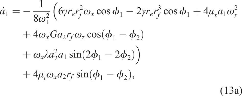
The first order solutions equation (8) along with the relations defined in equation (9) are substituted into the second order equation (6). The secular terms are omitted by equating the coefficients of
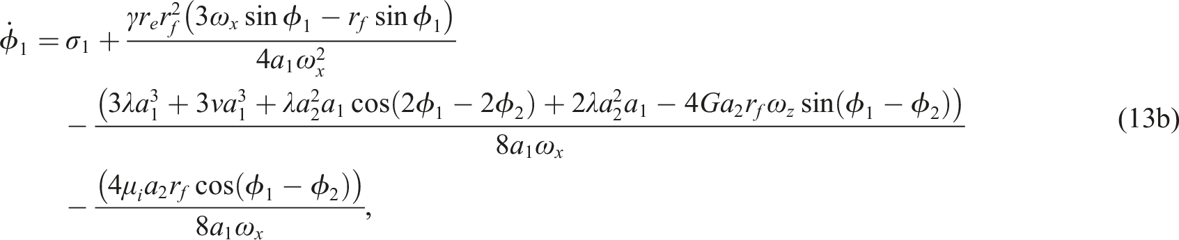
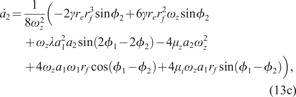
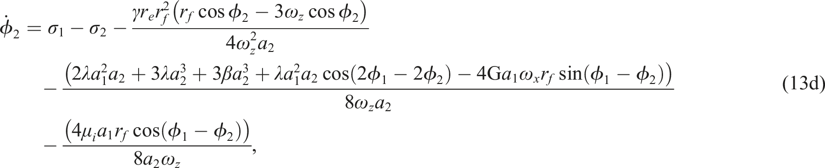
Linear stability analysis
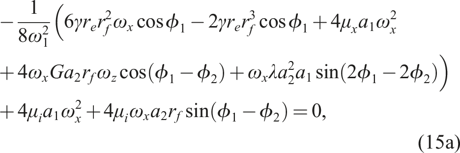
The conditions for determining the steady state oscillations
26
are written as

Substituting equation (13) into equation (14) we get,


The expression for
These conditions are utilized to determine the stability of steady-state solutions for certain cases discussed in Section 4.3.
Critical parameter values for the emergence of jump phenomenon for localized oscillation
In the case of localized oscillations, the governing equations are uncoupled along horizontal (
The equations governing the localized oscillations in the horizontal direction obtained by substituting
Setting
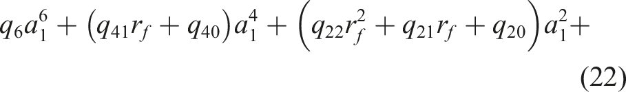
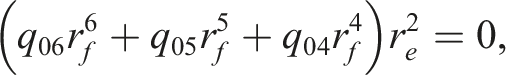
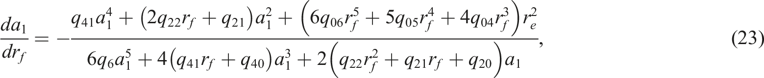
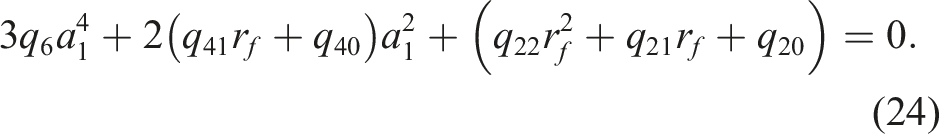
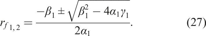
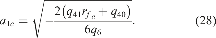
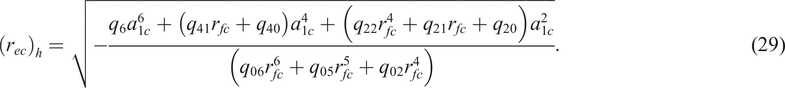
The roots of equation (24) are given by

Real roots of

Results and discussion
Independent parameters and its values.
The impact of different system parameters (such as 

As the gyroscopic parameter
Comparison of numerical and analytical results
The time-displacement responses obtained numerically by simulating equations (32) are compared with those obtained from the analytical expressions of the amplitude and phase equations (like equation (21) for horizontal oscillations). The comparisons shown in Figure 2 verifies the accuracy of the analytical results in comparison to the numerical results for the localized oscillations. This section presents some important results obtained either using the analytical expressions or numerical simulations of the governing equations. The CRS with internal damping is analysed through time-displacement response, phase-plane plots, and amplitude-frequency curves.
Dependent parameter values for different values of independent parameters of localized oscillations.
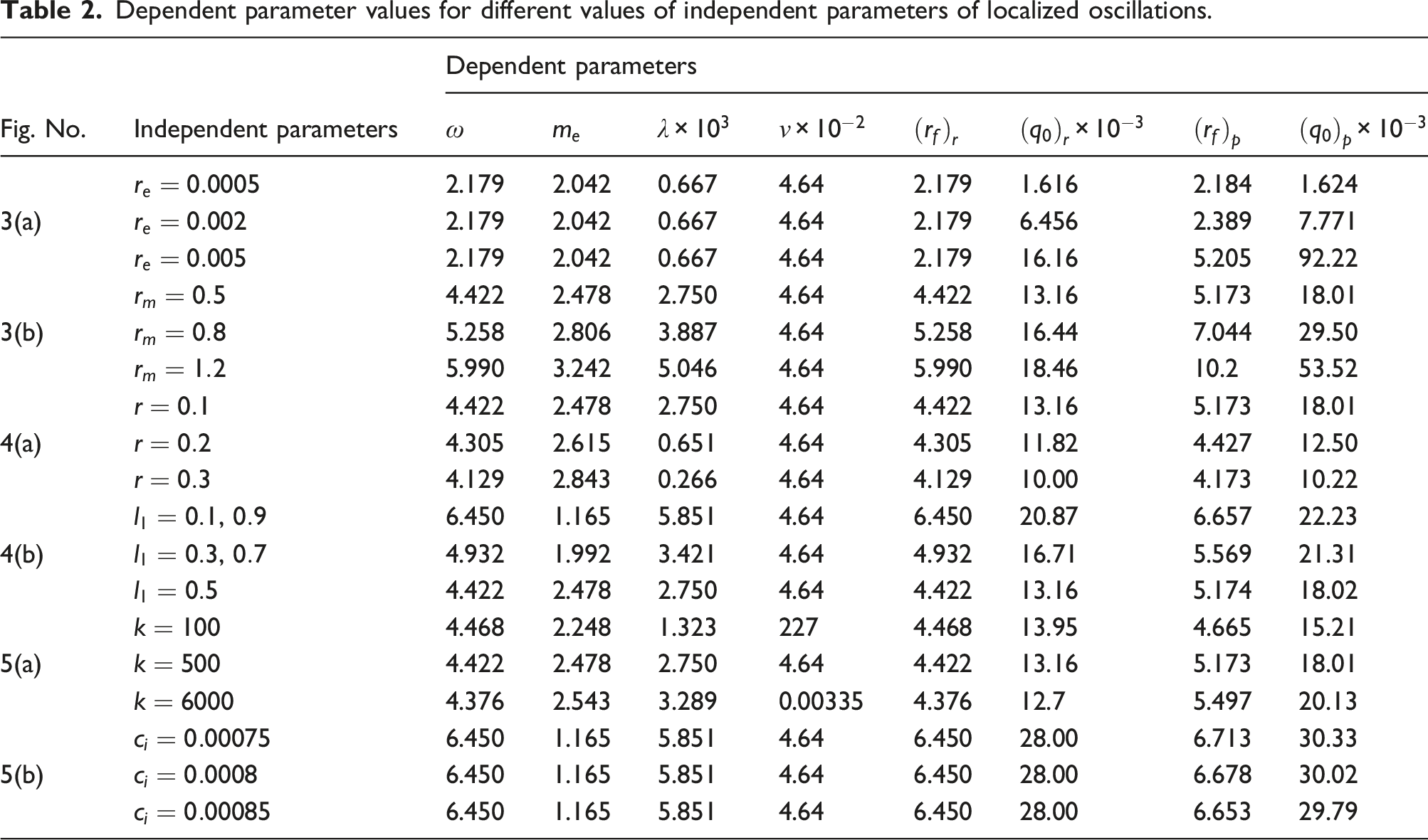
Figure 2 illustrates the comparison for a specific set of parameter values listed in Table 2. Both the time-displacement, phase-plane diagrams and amplitude frequency response curves in Figure 2(a) and 2(b) demonstrate the close match of the MMS results with the results obtained from numerical simulations. This verifies the accuracy of the expressions derived using the MMS. The accuracy of the analytical results is further verified through amplitude-frequency response plots of the linear system generated for the specific set of parameter values listed in Table 2, as illustrated in Figure 2(c). In Figure 2(c), the red solid lines represent numerical results obtained using equation (1). The plots demonstrate a strong agreement of the MMS results (equation (13)) with the exact numerical solutions. The ‘Matcont’ software, integrated within ‘MATLAB’, facilitated the generation of the response curve from equation (13).
Localized oscillations
Figure 3 illustrates the effect of eccentricity ratio Amplitude frequency response of rotor system for horizontal and vertical direction for various values of 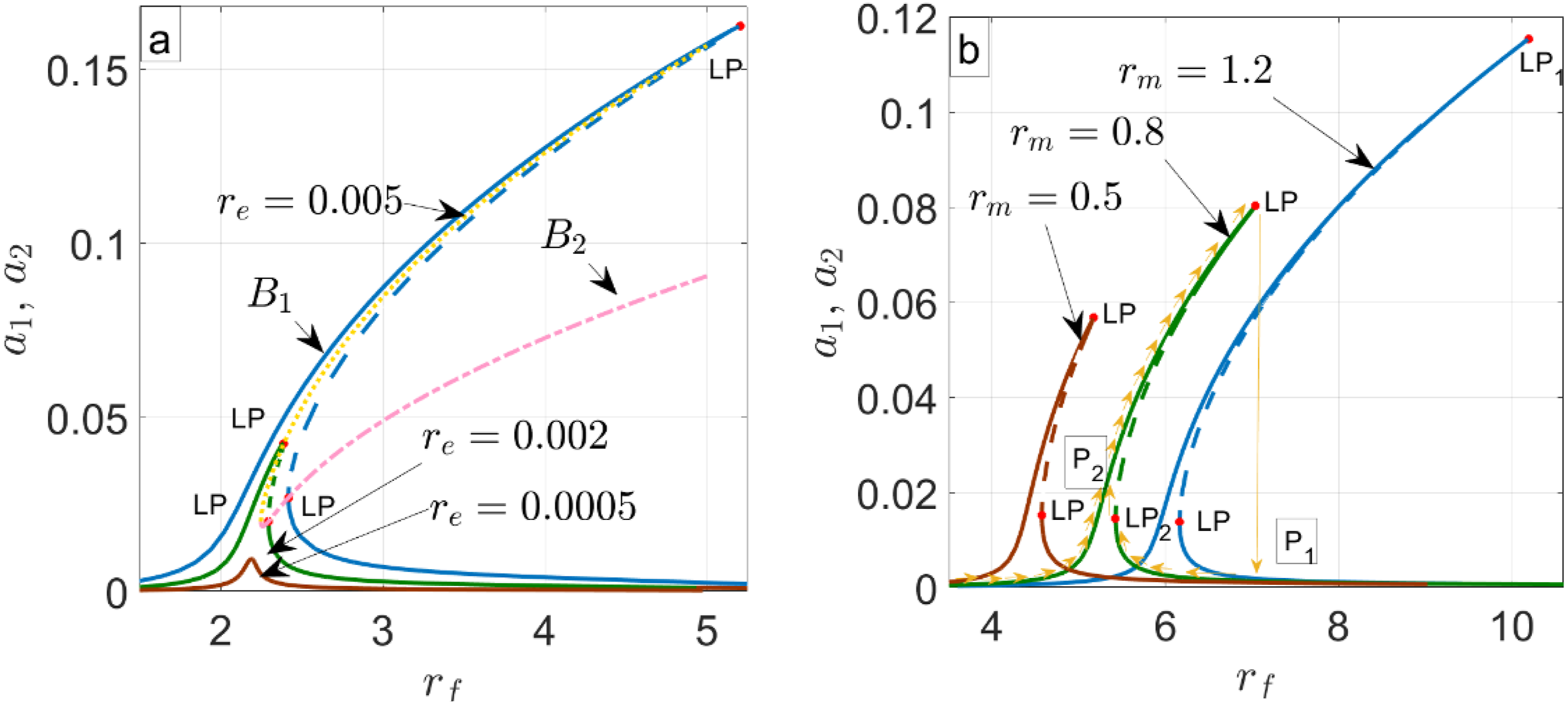
For
Due to space constraints and for better clarity, the jump phenomenon is depicted by arrows in Figure 3(b). As the excitation frequency is increased from a lower value to the limit point denoted by LP1, the amplitude of oscillation gradually increases. Further increase in the excitation frequency beyond this critical value results in a sudden jump in amplitude from a very high value at the upper branch to a very low value at the lower branch. The solutions stay in the lower branch for higher excitation frequencies than this critical value. If the excitation frequency is decreased from this critical value till the lower limit point denoted by LP2, the solutions stay on the lower branch. A further decrease in the excitation frequency results in another jump from small amplitude to the large amplitude of oscillation. In between LP1 and LP2, the middle branch corresponds to the unstable solutions. If the system is subjected to sudden disturbance while oscillating at a large amplitude at an excitation frequency in between LP1 and LP2 causing the state of the system to go below the middle branch, the solution will fall to the lower branch. Consequently, a sudden jump in the amplitude of oscillations can be observed in the time-displacement response. This makes it difficult to determine LP1 from experiments, particularly for situations where the gap between the upper and middle branch is very narrow.
The effect of mass ratio (
Figure 4(a) depicts the amplitude-frequency response plots for different values of radius of gyration ( Amplitude frequency response of rotor system for horizontal and vertical direction for various values of 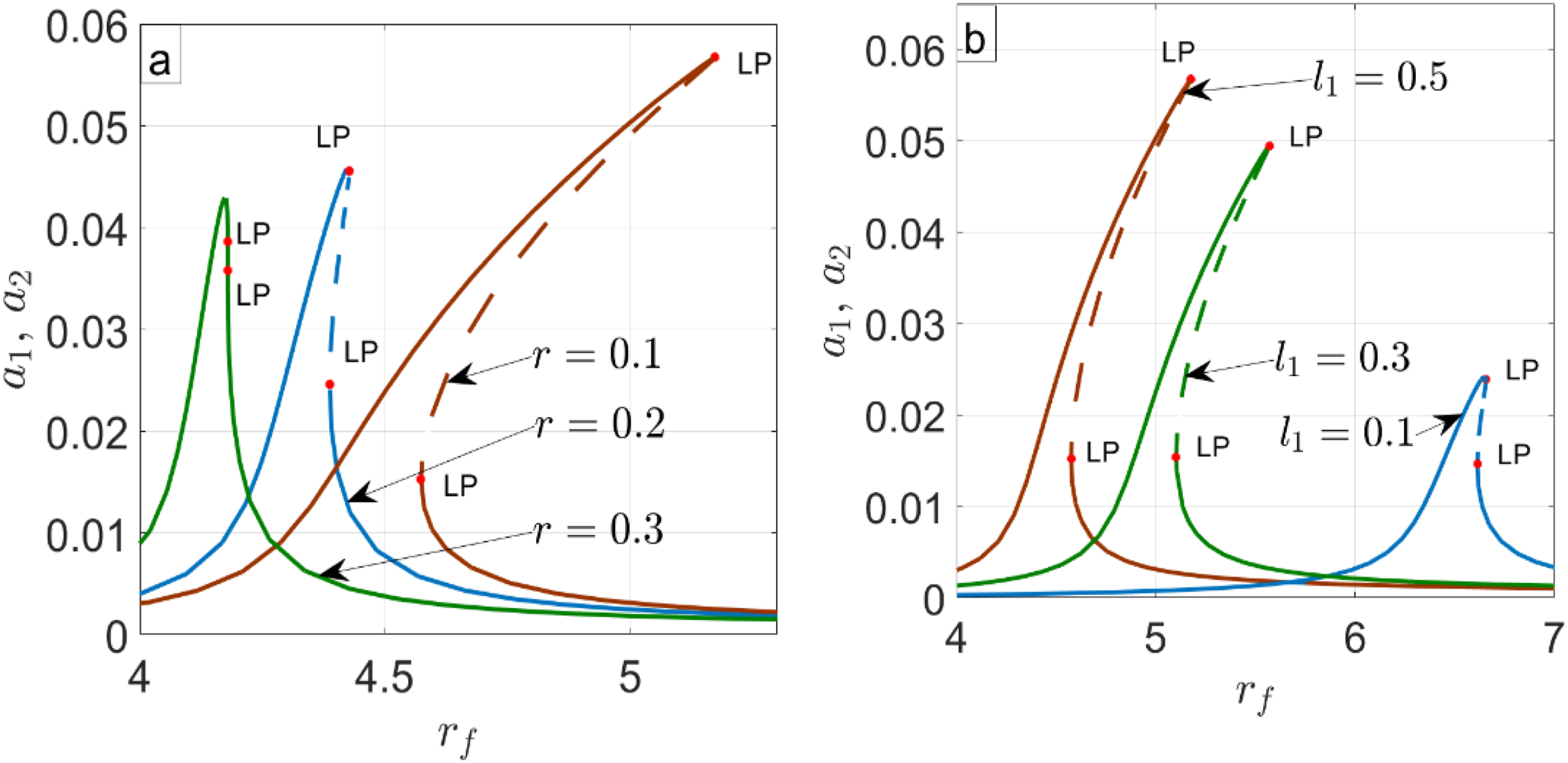
The effect of
The effect of spring stiffness Amplitude frequency response of rotor system for horizontal and vertical direction for various values of 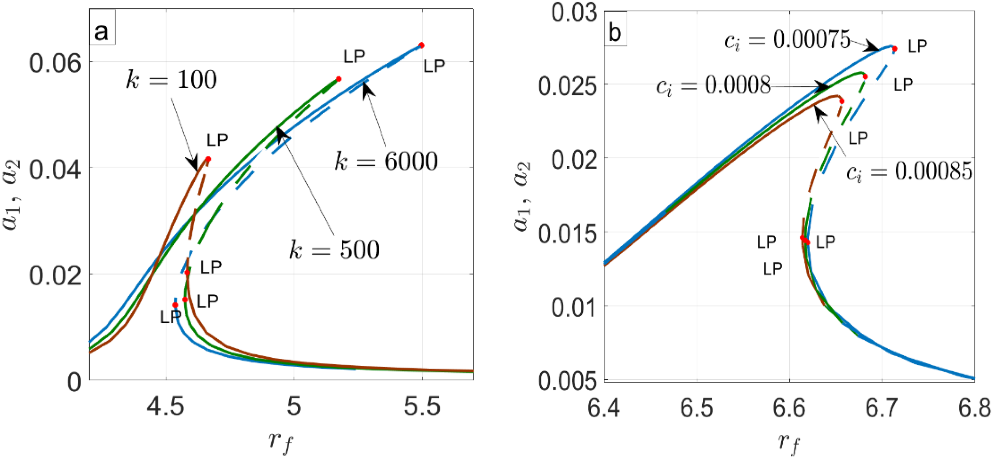
The effect of internal damping
Nonlocalized oscillations
Dependent parameter values for different values of independent parameters of nonlocalized oscillations.
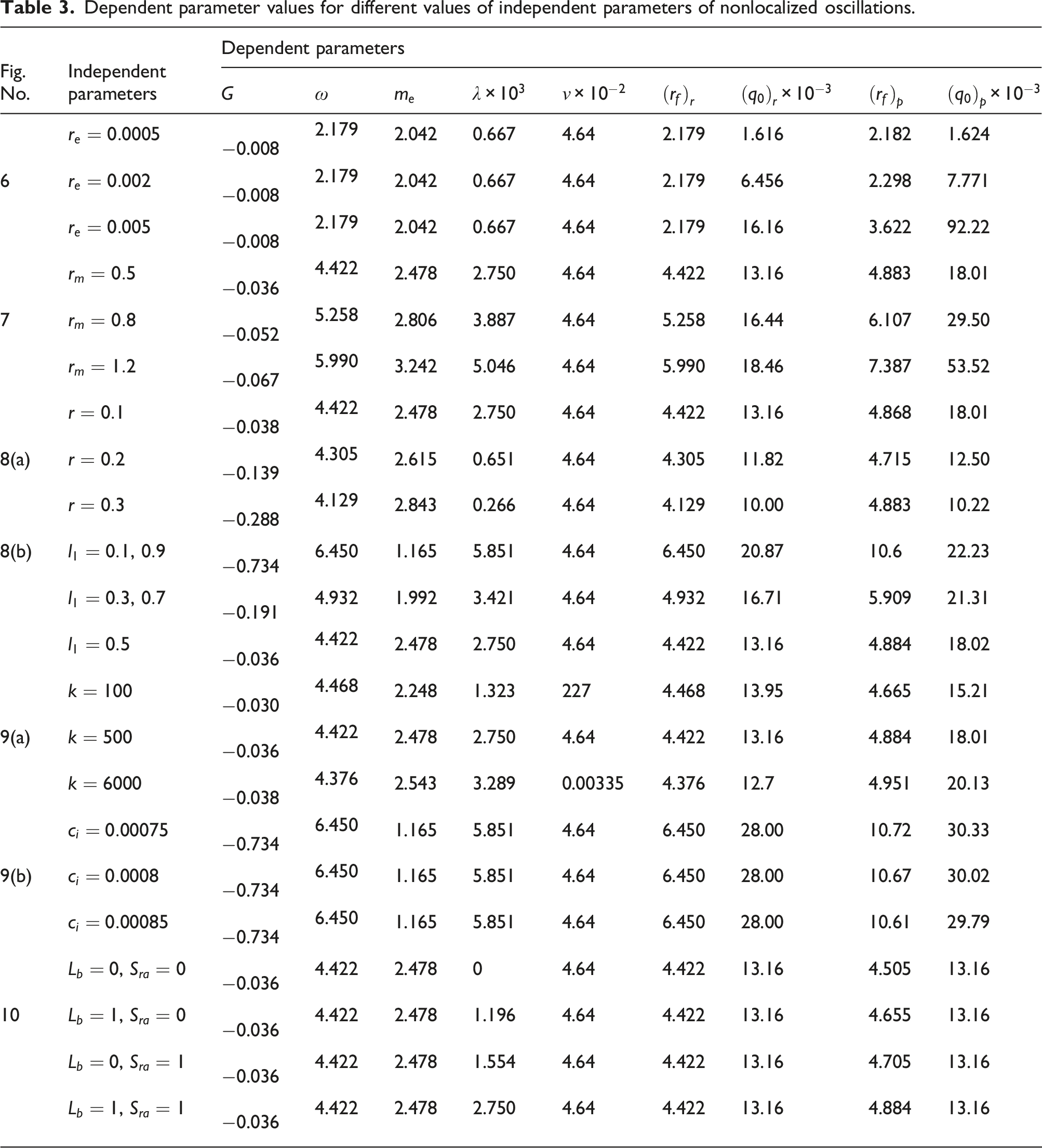
The influence of eccentricity ratio (a) Amplitude-frequency responses in horizontal and vertical direction, (b) phase plane plots for 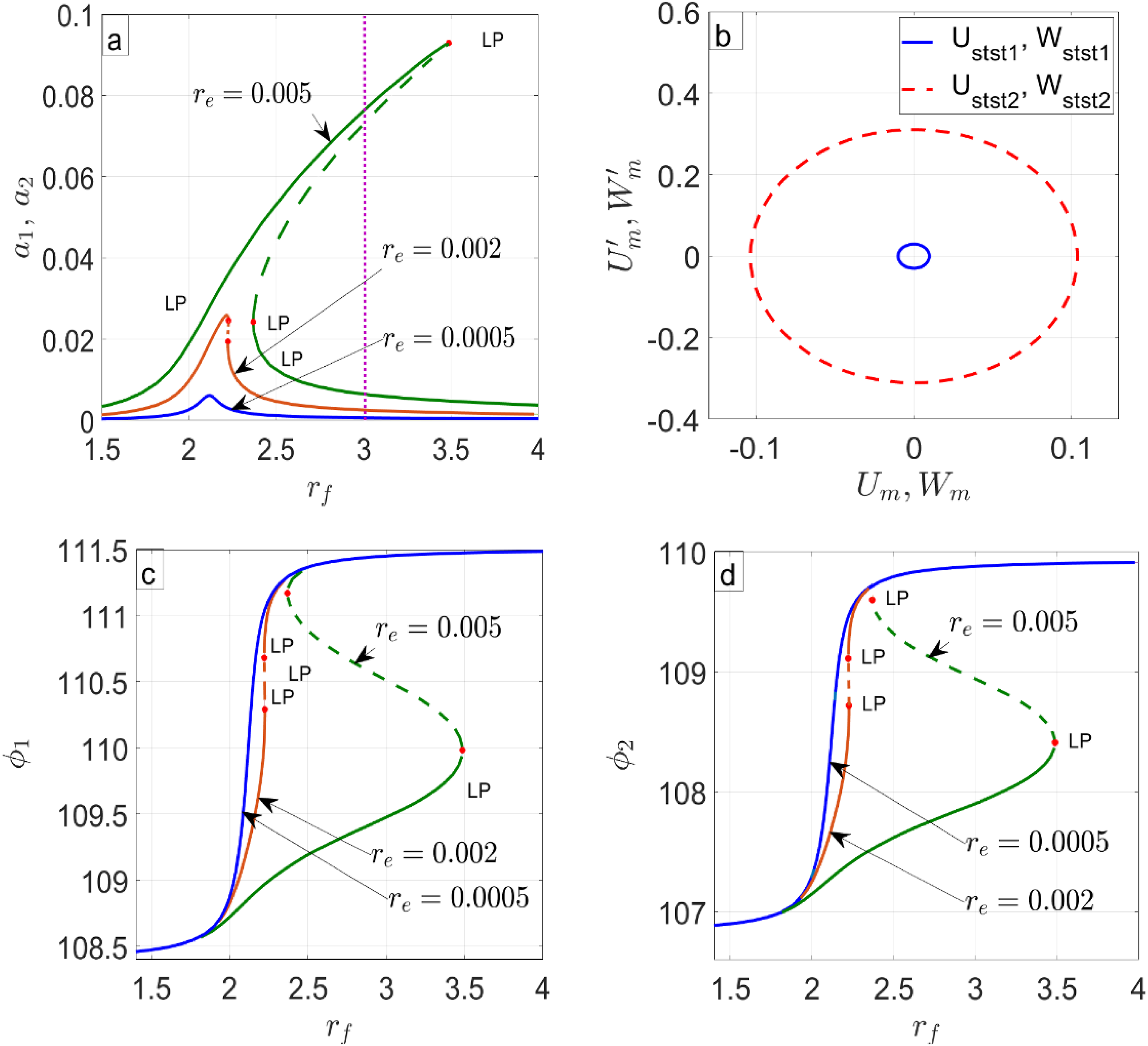
A sharp but continuous rise in the phase angle
The jump phenomenon can be explained in a similar way as in the case for localized oscillations. The arrows in Figure 7(a) are plotted to explain the jump phenomenon. When the excitation frequency is increased from a lower value, the solution remains in the upper branch of the curve until point Amplitude frequency responses in the horizontal and vertical direction for different values of 
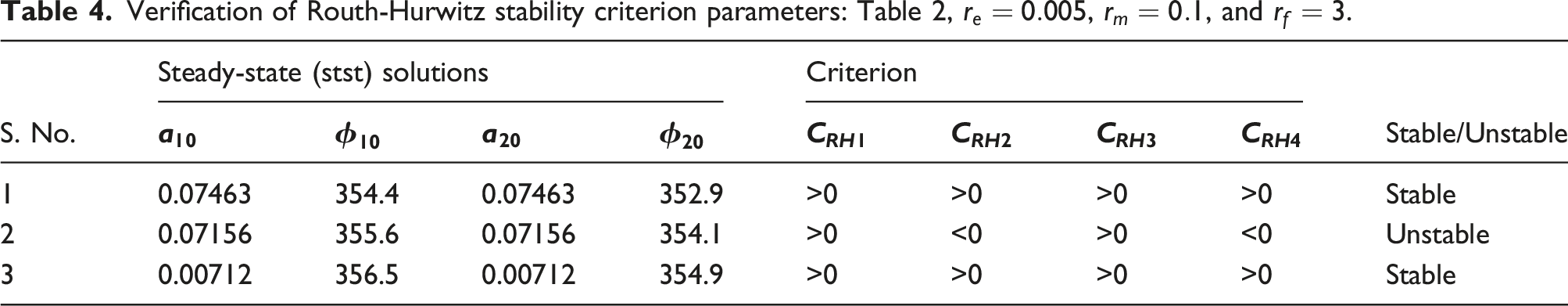
Verification of Routh-Hurwitz stability criterion parameters: Table 2,
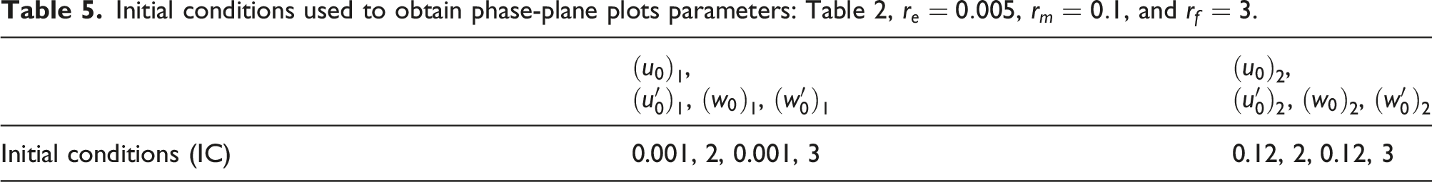
Initial conditions used to obtain phase-plane plots parameters: Table 2,
The mass ratio
The effects of radius of gyration of the shaft cross section
The position of the disc on the shaft is governed by the parameter Amplitude frequency responses in the horizontal and vertical direction for different values of 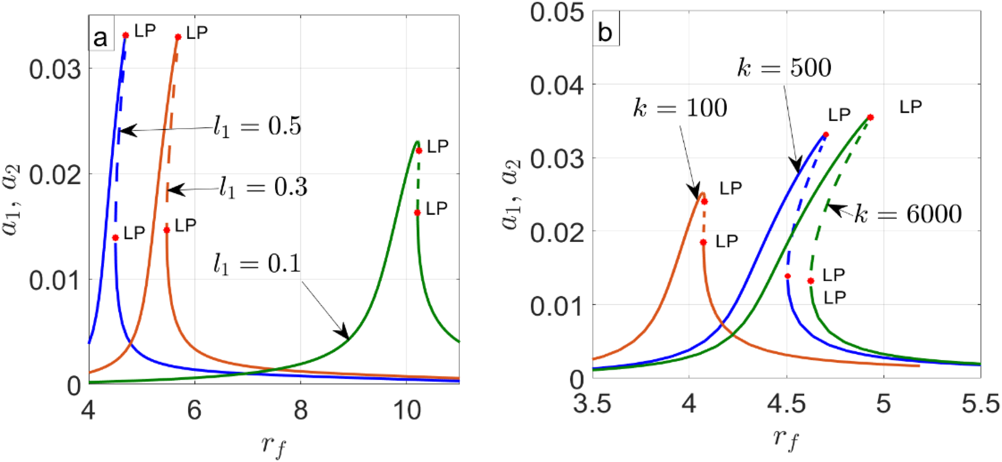
The natural frequency for
Parameter values for different values of internal damping coefficient.
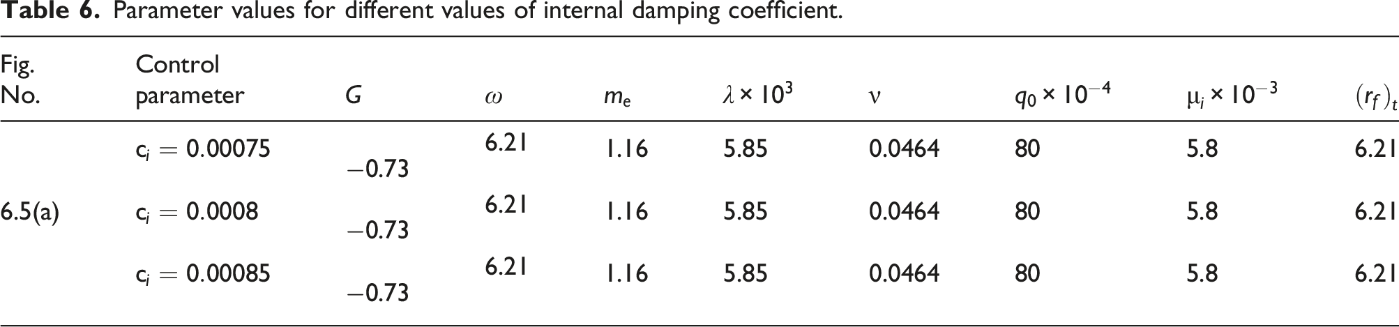
Figure 9(a) demonstrates the effect of internal damping Amplitude frequency plots in horizontal and vertical direction for various values of 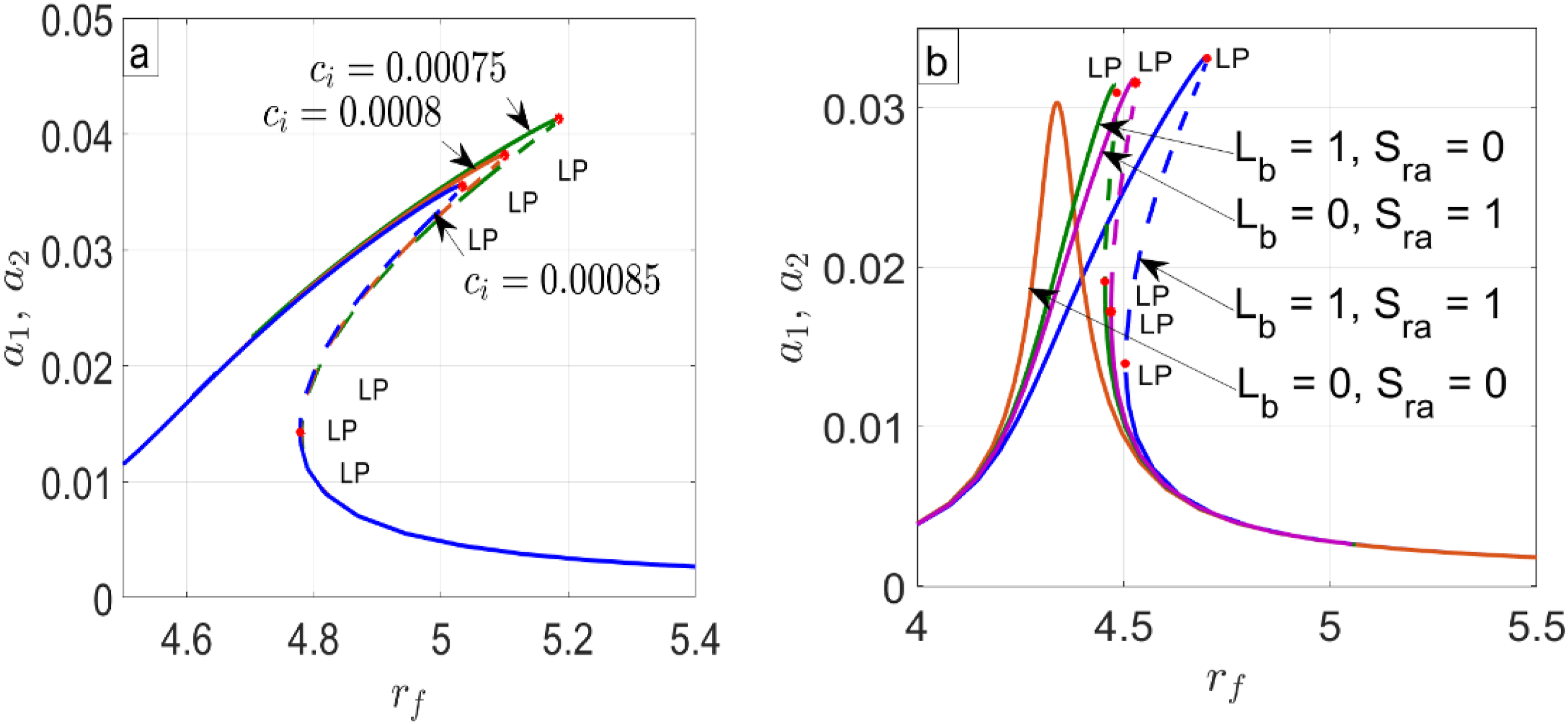
It is observed from equations (1) and (2) that the sources of nonlinearities in the rotor system are: (i) large beam deflection associated with the index
The frequency response curves for various internal damping factors ( Amplitude frequency response of rotor system for horizontal and vertical direction for various values of 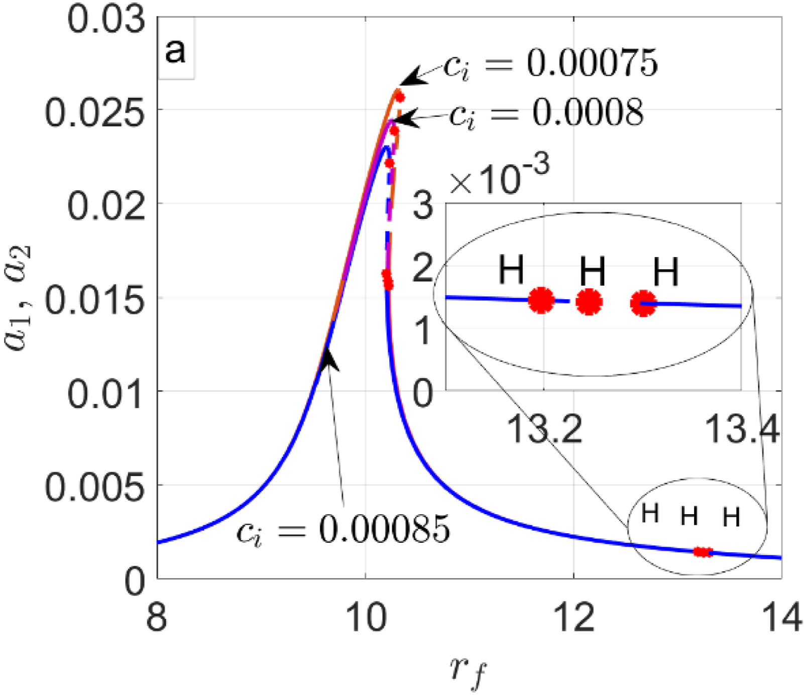
To verify the stability of steady-states, the time-displacement responses are plotted in Figure 11 for different values of Time response in horizontal and vertical direction for various values of 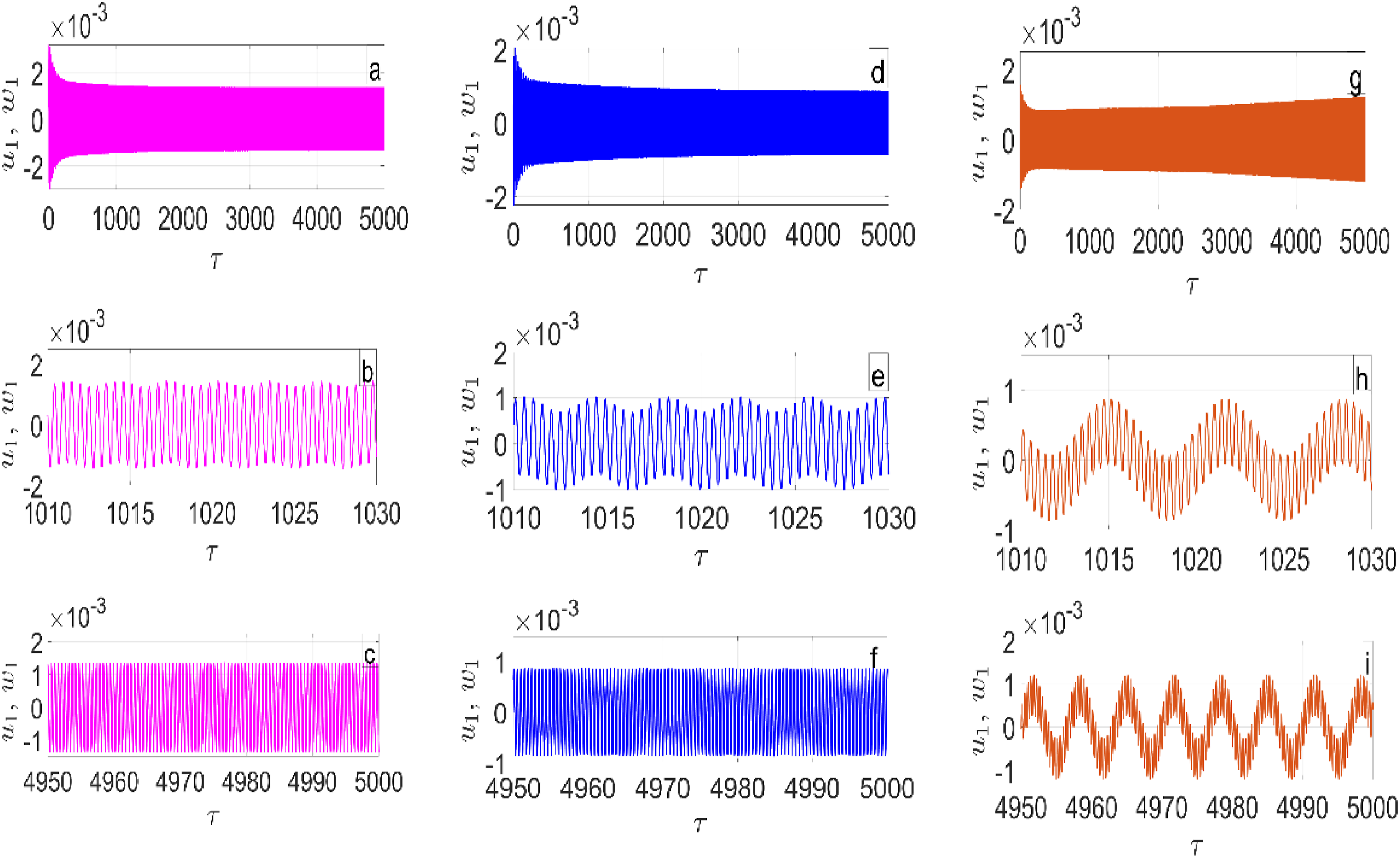
The possibility of obtaining different (forward and backward) whirling directions is explored in this section. The whirling direction can be predicted from the Campbell diagram. For a particular set of parameters, the Campbell diagram is shown in Figure 12(a). The one peak in the frequency response diagram for equal amount of damping along the horizontal and vertical directions ( Amplitude frequency response and Campbell diagram Parameter: Table 2, 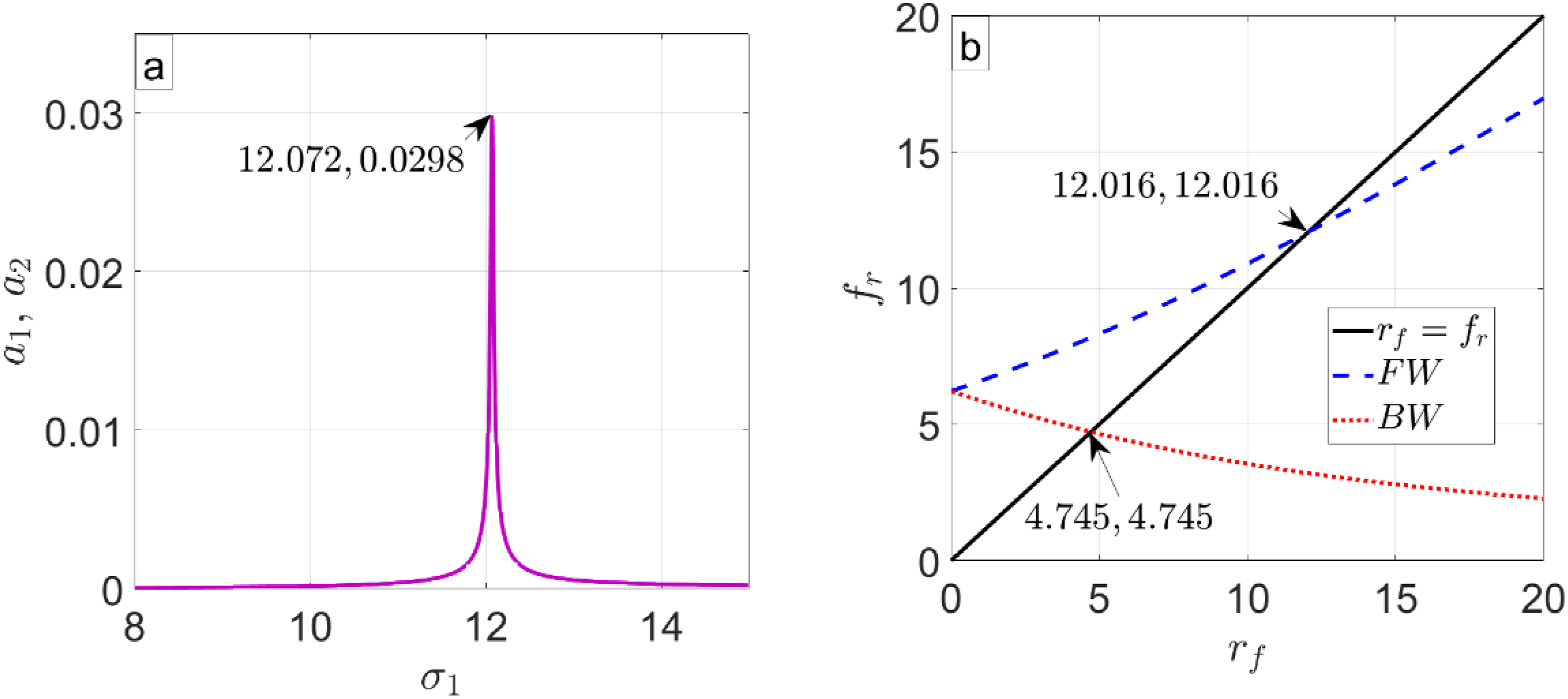
In this subsection, the whirling direction of the system is analyzed for Figure 13(a). The numerical simulations of the governing equations (1) are employed to determine the direction of whirling of CRS. Figure 13 presents the orbit plots for different values of Orbit plot for various values of 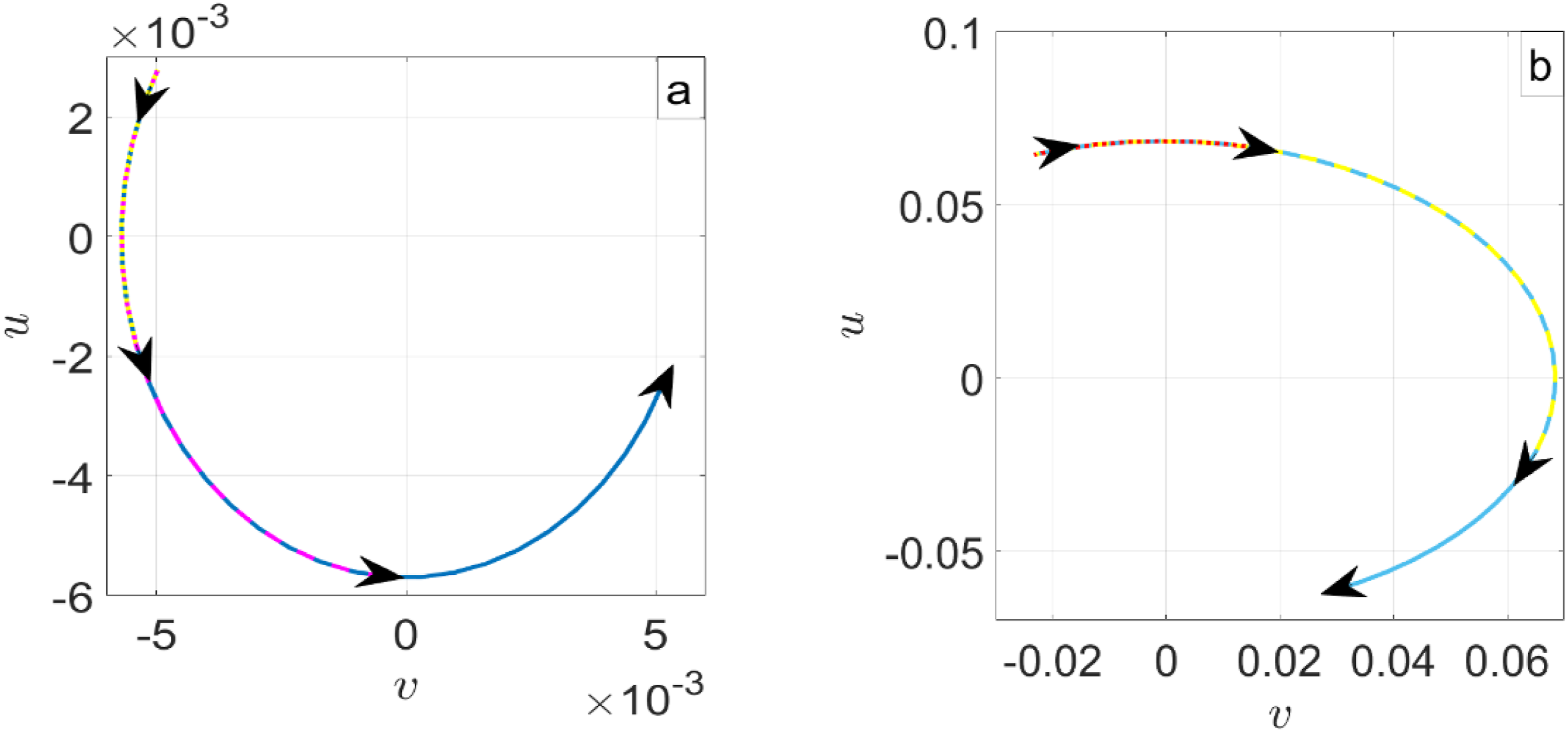
Conclusion
Nonlinear analysis of a continuous rotor system (CRS) with a rigid disc mounted on a flexible shaft is analysed in this paper. The support bearings are modelled as linear springs placed along the horizontal and vertical directions. Several factors influencing the dynamics of the rotor system are included in the CRS model. These influencing factors are the gyroscopic effect, the rotary inertia of the disc and shaft, large beam deformation of the shaft, restriction of the shaft axial motion at the bearing ends and internal damping. A nonlinear continuous rotor model that integrates multiple interacting effects within a single framework and provides analytical treatment of simultaneous resonance using the method of multiple scales, along with explicit prediction of bifurcation and instability conditions. The influencing factors are the sources of nonlinearities in the system’s governing equations. The method of multiple scales is used to derive autonomous amplitude-phase equations in the horizontal and vertical directions. The MATLAB ode solver is employed to simulate the governing equations to obtain the numerical results. These are used to verify the accuracy of the analytical results attained from the amplitude-phase equations. A detailed parametric study is performed though the amplitude-frequency response diagrams and phase angle-frequency plots. These plots are acquired from the numerical simulation of the amplitude-phase equations in Matcont, an add-on in MATLAB. Depending on the system parameters, multi-valued solutions for a particular range of excitation frequency are observed. The stability of these solutions is determined using the linear stability analysis.
Both the localized and nonlocalized oscillations are analysed. In case of localized oscillations, the equations governing the motion of the disc along the horizontal and vertical directions are decoupled (equations (32)). The nonlocalized oscillations are obtained from the original governing equation (1). Parametric studies are performed to determine the influence of the system parameters ( • Localized oscillations are independent of the gyroscopic parameter ( • System stiffness and natural frequency are strongly influenced by • The gyroscopic parameter ( • The nonlinear stiffness ratio
The system dynamics are connected to the system parameters in this study. This will be helpful in attaining a particular system design subjected to certain constraints in the system dynamics. There is a lot of potential to extend the current work in future. The bearing stiffness is assumed to be linear in the current work for the sake of simplicity. Derivation of the governing equations with the nonlinear stiffness at the bearings can be attempted in future. This will make the system more realistic.
Supplemental material
Supplemental material - Effect of internal damping on the stability of a non-linear continuous rotor system
Supplemental material for Effect of internal damping on the stability of a non-linear continuous rotor system by Amit Malgol, Ashesh Saha, Allen Anilkumar in Noise & Vibration Worldwide.
Footnotes
Author contributions
All authors contributed to the study conception and design. Material preparation, data collection and analysis were performed by Amit Malgol and Ashesh Saha. The first draft of the manuscript was written by Amit Malgol and all authors commented on previous versions of the manuscript. All authors read and approved the final manuscript.
Declaration of conflicting interests
The authors declared no potential conflicts of interest with respect to the research, authorship, and/or publication of this article.
Funding
The authors disclosed receipt of the following financial support for the research, authorship, and/or publication of this article: This work has been supported by DST SERB—SRG under Project File no. SRG/2019/001445 and National Institute of Technology Calicut under Faculty Research Grant. We are also grateful to Dr M. D. Narayanan for his support and advice.
Data Availability Statement
The datasets generated during and/or analysed during the current study are not publicly available due to ongoing research or future publications but are available from the corresponding author on reasonable request.
Supplemental material
Supplemental material for this article is available online.
Appendix
References
Supplementary Material
Please find the following supplemental material available below.
For Open Access articles published under a Creative Commons License, all supplemental material carries the same license as the article it is associated with.
For non-Open Access articles published, all supplemental material carries a non-exclusive license, and permission requests for re-use of supplemental material or any part of supplemental material shall be sent directly to the copyright owner as specified in the copyright notice associated with the article.